EP0498435A2 - Magneto-optical recording medium - Google Patents
Magneto-optical recording medium Download PDFInfo
- Publication number
- EP0498435A2 EP0498435A2 EP92102014A EP92102014A EP0498435A2 EP 0498435 A2 EP0498435 A2 EP 0498435A2 EP 92102014 A EP92102014 A EP 92102014A EP 92102014 A EP92102014 A EP 92102014A EP 0498435 A2 EP0498435 A2 EP 0498435A2
- Authority
- EP
- European Patent Office
- Prior art keywords
- layer
- reproduction
- recording
- emu
- magneto
- Prior art date
- Legal status (The legal status is an assumption and is not a legal conclusion. Google has not performed a legal analysis and makes no representation as to the accuracy of the status listed.)
- Granted
Links
Images


Classifications
-
- G—PHYSICS
- G11—INFORMATION STORAGE
- G11B—INFORMATION STORAGE BASED ON RELATIVE MOVEMENT BETWEEN RECORD CARRIER AND TRANSDUCER
- G11B11/00—Recording on or reproducing from the same record carrier wherein for these two operations the methods are covered by different main groups of groups G11B3/00 - G11B7/00 or by different subgroups of group G11B9/00; Record carriers therefor
- G11B11/10—Recording on or reproducing from the same record carrier wherein for these two operations the methods are covered by different main groups of groups G11B3/00 - G11B7/00 or by different subgroups of group G11B9/00; Record carriers therefor using recording by magnetic means or other means for magnetisation or demagnetisation of a record carrier, e.g. light induced spin magnetisation; Demagnetisation by thermal or stress means in the presence or not of an orienting magnetic field
- G11B11/105—Recording on or reproducing from the same record carrier wherein for these two operations the methods are covered by different main groups of groups G11B3/00 - G11B7/00 or by different subgroups of group G11B9/00; Record carriers therefor using recording by magnetic means or other means for magnetisation or demagnetisation of a record carrier, e.g. light induced spin magnetisation; Demagnetisation by thermal or stress means in the presence or not of an orienting magnetic field using a beam of light or a magnetic field for recording by change of magnetisation and a beam of light for reproducing, i.e. magneto-optical, e.g. light-induced thermomagnetic recording, spin magnetisation recording, Kerr or Faraday effect reproducing
- G11B11/10582—Record carriers characterised by the selection of the material or by the structure or form
- G11B11/10586—Record carriers characterised by the selection of the material or by the structure or form characterised by the selection of the material
-
- G—PHYSICS
- G11—INFORMATION STORAGE
- G11B—INFORMATION STORAGE BASED ON RELATIVE MOVEMENT BETWEEN RECORD CARRIER AND TRANSDUCER
- G11B11/00—Recording on or reproducing from the same record carrier wherein for these two operations the methods are covered by different main groups of groups G11B3/00 - G11B7/00 or by different subgroups of group G11B9/00; Record carriers therefor
- G11B11/10—Recording on or reproducing from the same record carrier wherein for these two operations the methods are covered by different main groups of groups G11B3/00 - G11B7/00 or by different subgroups of group G11B9/00; Record carriers therefor using recording by magnetic means or other means for magnetisation or demagnetisation of a record carrier, e.g. light induced spin magnetisation; Demagnetisation by thermal or stress means in the presence or not of an orienting magnetic field
- G11B11/105—Recording on or reproducing from the same record carrier wherein for these two operations the methods are covered by different main groups of groups G11B3/00 - G11B7/00 or by different subgroups of group G11B9/00; Record carriers therefor using recording by magnetic means or other means for magnetisation or demagnetisation of a record carrier, e.g. light induced spin magnetisation; Demagnetisation by thermal or stress means in the presence or not of an orienting magnetic field using a beam of light or a magnetic field for recording by change of magnetisation and a beam of light for reproducing, i.e. magneto-optical, e.g. light-induced thermomagnetic recording, spin magnetisation recording, Kerr or Faraday effect reproducing
- G11B11/10502—Recording on or reproducing from the same record carrier wherein for these two operations the methods are covered by different main groups of groups G11B3/00 - G11B7/00 or by different subgroups of group G11B9/00; Record carriers therefor using recording by magnetic means or other means for magnetisation or demagnetisation of a record carrier, e.g. light induced spin magnetisation; Demagnetisation by thermal or stress means in the presence or not of an orienting magnetic field using a beam of light or a magnetic field for recording by change of magnetisation and a beam of light for reproducing, i.e. magneto-optical, e.g. light-induced thermomagnetic recording, spin magnetisation recording, Kerr or Faraday effect reproducing characterised by the transducing operation to be executed
Definitions
- the present invention relates to a magneto-optical recording medium, and particularly a magneto-optical recording medium of high resolution.
- a magneto-optical recording and reproduction method local heating by irradiation with laser light is carried out to form information record pits, or bubble domains, and the recorded information is read through a magneto-optical interaction, i.e. the Kerr effect or the Faraday effect.
- a magneto-optical interaction i.e. the Kerr effect or the Faraday effect.
- increasing the density of magneto-optical recording may be accomplished by reducing the size of the record pits.
- a problem arises as to the resolution (resolving power) in reproduction.
- the resolution is determined by the laser wavelength ⁇ and the numerical aperture N.A. of an objective lens which are used for reproduction.
- Figure 1A shows a schematic top plan of a record pattern, in which a magneto-optical recording medium 3 such as a magneto-optical disk has record pits 4 (hatched areas) formed, for instance, according to two-valued information "0" and "1", in a land portion 2 bounded on both sides by grooves 1, for example.
- the method of reproduction in use of such a magneto-optical recording medium will be explained, with reference to the case where the beam spot of reading laser light incident on the magneto-optical recording medium 3 is a circular spot, as is denoted by reference sign 5.
- the record pits 4 are arranged in high density as shown in a schematic top plan of a record pattern in Figure 2A, a plurality of record pits 4 come under the beam spot 5 simultaneously.
- the reproduction output obtained when the adjacent record pits 4a and 4b are located in a single beam spot 5 does not differ from the reproduction output obtained when the record pits 4b and 4c are located in the beam spot 5, as shown in Figures 2B and 2C. Therefore, the reproduction output waveform will be, for example, rectilinear as shown in Figure 2D, and the reproduction outputs in the above two situations cannot be distinguished from each other.
- the record pits 4 formed on the magneto-optical recording medium 3 are kept as they are during reading of recorded information. Therefore, even if high-density recording, i.e. formation of record pits in a high density, is accomplished, a high S/N (C/N) cannot be obtained due to limitations as to resolution in reproduction. In short, satisfactory high density recording and reproduction cannot be achieved according to the conventional magneto-optical recording and reproduction system.
- MSR superhigh-resolution magneto-optical system for recording and reproduction
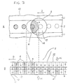
- Figure 3A is a schematic top plan showing a record pattern on a magnets-optical recording medium 10
- Figure 3B is a schematic sectional view showing a magnetization mode of the same.
- the magneto-optical recording medium 10 is moved in the direction of arrow D, relative to a laser beam spot 5.
- the magneto-optical recording medium 10 such as a magneto-optical disk used here comprises at least a reproduction layer 11 composed of a perpendicular magnetization film and a recording layer 13; preferably, the recording medium 10 further comprises an intermediate layer 12 interposed between the layers 11 and 13.
- Arrows in the layers 11, 12 and 13 each represent schematically the orientation of a magnetic moment.
- the downward orientation corresponds to an initialized state.
- Information record pits 4 in the form of magnetic domains are formed at least in the recording layer 13 by upward magnetization, as viewed in the figure.
- a reproducing magnetic field Hr in the opposite direction to the initializing field Hi is applied to the magneto-optical recording medium 10, at least in a reproduction area thereof.
- the region including the latent record pits 41 initialized as above comes to fall under the beam spot 5.
- a substantially high-temperature region 14 encircled with broken line (a) and hatched in the figure is generated on the front end side of the spot 5.
- the domain wall at the intermediate layer 12 is lost, and the magnetization of the recording layer 13 is transferred to the reproduction layer 11 by exchange force.
- the latent record pits 41 present in the recording layer 13 are duplicated in relief in the reproduction layer 11, as reproducible record pits 4.
- the initializing magnetic field Hi, reproducing magnetic field Hr as well as the coercive force, thickness, magnetization and domain wall energy of each magnetic layer, etc. are selected according to the temperatures of the high-temperature region 14 and low-temperature region 15 in the beam spot 5.
- Equation 1 (Equation 1) Hi > H c1 + ⁇ w2 /2M s1 h1 where ⁇ w2 is the interfacial domain wall energy between the reproduction layer 11 and the recording layer 13.
- Equation 3 H c1 > ⁇ w2 /2M s1 h1
- Equation 4 H c1 - ⁇ w2 /2M s1 h1 ⁇ H r ⁇ H c1 + ⁇ w2 /2M s1 h1
- the magnetization of the latent record pits 4 in the recording layer 13 can be transferred to the reproduction layer 11, that is it is duplicated in relief as record pits 41 in the reproduction layer 11, and only in the area where the domain wall formed by the intermediate layer 12 is present.
- magnétique recording medium 10 used for the MSR system above has been explained with reference to a three-layer structure comprising the reproduction layer 11, intermediate layer 12 and recording layer 13, a four-layer structure may also be adopted in which a reproduction sub-layer 31 is provided on the side of the intermediate layer 12 with respect to the reproduction layer 11, as illustrated by a schematic sectional view thereof in Figure 4.
- the reproduction sub-layer 31 functions in aid of the characteristics of the reproduction layer 11, and compensates for the coercive force of the reproduction layer 11 at room temperature.
- the presence of the reproduction sub-layer 31 ensures that the magnetization of the reproduction layer 11 aligned by the initializing magnetic field Hi can exist in stable fashion in the presence of the domain wall, and the coercive force of the reproduction layer 11 is reduced drastically in the vicinity of the reproduction temperature.
- the domain wall is confined in the intermediate layer 12 and is permitted to spread into the reproduction sub-layer 31 to finally reverse the magnetization of the reproduction layer 11. This is accompanied by disappearance of the domain wall.
- the record pits in the recording layer 13 can be duplicated in relief in the reproduction layer 11 in an improved manner.
- the coercive force H c1 of the reproduction layer 11 is replaced by H CA defined by the following Equation 5, and ⁇ w2 /M S1 h1 by ⁇ w2 /(M s1 h1 + M s1s h 1s ).
- H CA (M s1 h1H c1 + M s1s h 1s H c1s )/(M s1 h1 + M s1s h 1s ) (in the foregoing relief type MSR, H c1 ⁇ H CA ⁇ H c1s ) where M s1s, H c1s and h 1s respectively represent the magnetization, coercive force and thickness of the reproduction sub-layer 31.
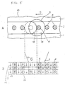
- Figure 5A is a schematic top plan showing a record pattern or a magneto-optical recording medium 10
- Figure 5B is a schematic sectional view showing a magnetization mode thereof.
- component parts corresponding to those in Figures 3A and 3B are denoted by the same reference signs as used in Figures 3A and 3B, and the explanation of those parts will not be repeated.
- This MSR system does not require an initializing magnetic field Hi.
- Equation 6 In a reproduction mode of the magneto-optical recording medium 10, the condition expressed by the following Equation 6 is fulfilled in a high-temperature region 14.
- the magnetization in the high-temperature region 14, even if in a laser beam spot 5, is aligned in the downward direction by a reproducing magnetic field Hr applied externally. Consequently, record pits 4 in a reproduction layer 11 disappear.
- the extinction type MSR system is designed so that reproduction can be performed only for the record pits 4 present in a low-temperature region 15 located in the beam spot 5, thereby offering an improved resolution.
- Equation 6 Hr > H c1 + ⁇ w2 /2M s1 h1
- conditions such as the coercive force of a recording layer 13 are set so that even after the extinction (disappearance) of the record pits 4 in the reproduction layer 11, the record pits 4 in the recording layer 13 are left as latent record pits 41. It is thereby ensured that, at room temperature, the magnetization of the recording layer 13, namely, the information pits 4 in the layer 13 are transferred to the reproduction layer 11 and held in the reproducible state.
- the record pits located in a part of the area of the reproducing laser beam spot are reproduced, so as to attain an enhanced resolution in reproduction.
- a magneto-optical recording medium 10 located under a beam spot 5 is provided with a temperature distribution in which temperature becomes lower from the forward side toward the backward side with respect to the moving direction of the recording medium relative to the beam spot 5, resulting in the formation of a high-temperature region 14, an intermediate-temperature region 16 and a low-temperature region 15 in the area of the beam spot 5, as shown in Figure 6.
- the high-temperature region 14 is made to have the function of the extinction type as explained above with reference to Figure 5, while the intermediate-temperature region 16 and the low-temperature region 15 are made to function respectively as the high-temperature region 14 and low-temperature region 15 as explained above with reference to Figure 1.
- the record pit 4 to be developed in relief in the reproduction layer 11, represented by hatching in Figure 6, can be present only in the limited, intermediate-temperature region 16 defined between the high-temperature region 14 and the low-temperature region 15. A higher resolution can be thereby achieved.
- the MSR systems enable a wavelength selection for the reading light to be made taking into account the magneto-optical effect, the temperature rise due to light absorption, the sensitivity of a light detector and the like, without adhering to the use of a shorter wavelength.
- a semiconductor laser light with a comparatively long wavelength (780 nm), for example, can be used as the reading light, to obtain a high reproduction resolution.
- a reproduction layer 11 is composed mainly of GdFeCo and has a saturation magnetization of at least 450 emu/cc and a coercive force of not more than 4 kOe.
- a recording layer is composed mainly of TbFeCo, and has a coercive force of at least 5 kOe.
- the recording layer has a magnetization of not more than 300 emu/cc if it is a transition metal-predominant film, and has a magnetization of not more than 200 emu/cc when it is a rare earth-predominant film.
- a magneto-optical recording medium 100 which comprises at least a reproduction layer 110, a recording layer 130 and an intermediate layer 120 interposed therebetween, the layers being so stacked that the adjacent ones thereof are magnetically coupled, and from which recorded signals are read through changing the state of magnetization of the reproduction layer under irradiation with reading light. It is assumed that the reproduction layer 110 and the recording layer 130 have saturation magnetization (M s ) values of M s1 and M s3 and coercive force (H c ) values of H c1 and H c3 , respectively.
- M s saturation magnetization
- H c coercive force
- the reproduction layer 110 comprises a rare earth-transition metal magnetic layer containing GdFeCo as a main constituent, and satisfies M s1 ⁇ 450 emu/cc and H c1 ⁇ 4 kOe at room temperature.
- the recording layer 13 comprises a rare earth-transition metal magnetic layer containing TbFeCo as a main constituent, satisfies H c3 ⁇ 5 kOe, and also satisfies either M s3 ⁇ 300 emu/cc or M s3 ⁇ 200 emu/cc, depending on whether the recording layer is a TM (transition metal) rich film or an RE (rare earth) rich film.
- Recording of information, or formation of record pits 4, on the magneto-optical recording medium 100 according to this invention is carried out at least in the recording layer 130.
- the information recording can be made, for example, by the magnetic field modulation system.
- Reading of information from the magneto-optical recording medium 100, for example a magneto-optical disk, having information thus recorded as record pits 4 in the recording layer 130 is carried out in the manner as shown in Figure 8, in which a linearly polarized laser beam L of semiconductor laser light (wavelength 780 nm) is focused by an objective lens 71 on the medium 100 revolving in the direction of arrow D, from the side of a substrate 20 as explained with reference to Figure 1.
- a linearly polarized laser beam L of semiconductor laser light (wavelength 780 nm) is focused by an objective lens 71 on the medium 100 revolving in the direction of arrow D, from the side of a substrate 20 as explained with reference to Figure 1.
- the record pit 4 is read by detecting the difference between the rotation of the polarization plane in the pit area, especially at the reproduction layer 110, by the Kerr effect and the corresponding rotation in the other (non-pit) areas.
- a reproducing field generating means 72 is provided by which a reproducing magnetic field Hr, developed by a required DC magnetic field orthogonal to the plane of the medium 10, is applied to the area including the part of the medium 10 irradiated with the beam spot 5 of the laser beam L.
- an initializing field generating means 73 is provided by which a DC initializing magnetic field Hi, directed opposite to the reproducing magnetic field Hr, is applied to a part of the medium 10 not yet brought under the beam spot 5.
- reproduction is carried out according to the relief type MSR system as explained with reference to Figures 3 and 4, or according to a combination of the relief type and extinction type as explained with reference to Figure 6; namely, the reproduction is carried out by a reading system which at least comprises developing (or duplicating) the record pits 4 in relief into the recording layer 110.
- the magneto-optical disk may be fabricated by sequentially providing, as for instance by sputtering, a dielectric film 23 composed of SiN or the like with an exemplary thickness of 800 ⁇ , a magneto-optical recording layer 21, and a protective film 25 composed of SiN or the like with an exemplary thickness of 800 ⁇ on a light-transmitting substrate 20 formed of a glass, a polycarbonate resin, or the like.
- the magneto-optical recording layer 21 may have a three-layer structure which, as explained with reference to Figure 3, comprises a reproduction layer 11, an intermediate layer 12 and a recording layer 13 in successive magnetic coupling.
- a four-layer structure which, as explained with reference to Figure 4, comprises a reproduction layer 11, a reproduction sub-layer 31, an intermediate layer 12 and a recording layer 13 with successive magnetic couplings may also he adopted. This produces an advantageous effect in, for example, compensating for the coercive force of the reproduction layer 11 at room temperature.
- the reproduction layer 110, reproduction sub-layer 31, intermediate layer 120 and recording layer 130 constituting the magneto-optical recording layer 21 can be formed by successive sputtering.
- the reproduction layer 110 comprises, for example, GdFeCo as a main constituent, to which Cr of the like may be added, as required, for enhancing reliability, and Nd or the like for adaptation to a shorter wavelength laser light.
- the thickness H1 of the reproduction layer 110 is so selected that the layer 110 is thick enough to obtain a sufficient Kerr effect in reproduction, and that the required temperature distribution can be obtained without needing an excessively high reproduction power. Namely, the thickness h1 is selected in the range of 150 to 1000 ⁇ .
- the Curie temperature T c1 of the reproduction layer 110 is so selected that the Kerr rotation angle ⁇ K is not deteriorated due to the temperature rise caused by the irradiation with laser light for reproduction.
- the Curie temperature T c1 is selected, on a functional basis, to be about 200°C or above.
- the saturation magnetization M s1 of the reproduction layer 110 is in the range of 0 ⁇ M s1 ⁇ 450 emu/cc (at room temperature) in the case of TM-rich film compositions, and in the range of 0 ⁇ M s1 ⁇ 350 emu/cc in the case of RE-rich film compositions.
- the reproduction sub-layer 31 is composed of a magnetic layer whose main constituent is TbFeCo, for example, and which has a saturation magnetization M s1s of 100 to 600 emu/cc in the case of TM-rich film compositions (at room temperature).
- the coercive force H c1s of the reproduction sub-layer 31 is preferably 7 kOe or below, provided that H CA defined by the above Equation 5 is not more than 4 kOe.
- the Curie temperature T c1s of the layer 31 is about 60 to 100°C.
- the reproduction sub-layer 31 is constituted mainly of a TbFeCo-based material, to which traces of Gd, Cr, Nd, Dy or Al may be added so as to control the characteristics of the layer, especially the temperature characteristic of the coercive force H c1s .
- the intermediate layer 120 is composed of a magnetic layer consisting mainly of GdFeCo, for example.
- the saturation magnetization M s2 of the layer 120 is in the range of 0 ⁇ M s2 ⁇ 700 emu/cc in the case of TM-rich film compositions, and in the range of 0 ⁇ M s2 ⁇ 200 emu/cc in the case of RE-rich film compositions.
- Compensation temperature of the intermediate layer 120 may be 100°C or below, and a film thickness h2 of not less than about 50 ⁇ may be sufficient.
- the recording layer 130 is composed of a magnetic layer of which the main constituent is TbFeCo, for example, and the saturation magnetization M s3 is in the range of 0 ⁇ M s3 ⁇ 300 emu/cc in the case of TM-rich film compositions and 0 ⁇ M s3 ⁇ 200 emu/cc in the case of RE-rich film compositions.
- a thickness h3 of not less than about 200 ⁇ may be sufficient.
- the saturation magnetization herein is represented by the value at room temperature.
- the dielectric film 23 was composed of an SiN film with 800 ⁇ thickness
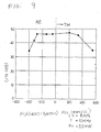
- the results are shown in Figure 9.
- C/N of 40 dB or above can be obtained at a magnetization of 0 ⁇ M s1 ⁇ 450 emu/cc with TM-rich film compositions, and 0 ⁇ M s1 ⁇ 350 emu/cc with RE-rich film compositions.
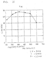
- the magneto-optical disk obtained in Embodiment 1 was subjected to another series of measurements of C/N under the same conditions as above, with the composition of the reproduction sub-layer 31 being varied. Namely, measurement of C/N versus magnetization M s1s of the layer 31 was carried out at room temperature by varying the Tb content of TbFeCo, to give the results as shown in Figure 10. The results show that a C/N of 40 dB or above can be obtained at a magnetization of 100 to 600 emu/cc with TM-rich film compositions.
- H c1s ⁇ 7 kOe and H CA ⁇ Hi are fulfilled.
- the magneto-optical disk obtained in Embodiment 1 was subjected to a measurement of C/N under the same conditions as above, with the composition of the intermediate layer 130 being varied. Namely, measurement of C/N versus magnetization M s2 of the layer 130 was carried out at room temperature by varying the Gd content of GdFeCo, to give the results as shown in Figure 11. The results show that a C/N of 40 dB or above can be obtained at M s2 ⁇ 700 emu/cc with TM-rich film compositions, and at M s2 ⁇ 200 emu/cc with RE-rich film compositions.
- the magneto-optical disk obtained according to Embodiment 1 was subjected to a measurement of C/N under the same conditions as above, with the composition of the recording layer 130 being varied. Namely, a measurement of C/N versus M s3 was carried out at room temperature by varying the Tb content of TbFeCo to give the results as shown in Figure 12. The results show that a C/N of 40 dB or above can be obtained at a magnetization of 0 ⁇ M s1 ⁇ 450 emu/cc with TM-rich film compositions, and at a magnetization of 0 ⁇ M s1 ⁇ 350 emu/cc with RE-rich film compositions.
- the above GdFeCo, TbFeCo and the like are ferromagnetic materials, in which the sublattice magnetization of rare earth metals such as TbGd, etc. and the sublattice magnetization of transition metals such as FeCo, etc. are always opposite to each other.
- the saturation magnetization M s is the balance of the two kinds of sublattice magnetization.
- the saturation magnetization M s decreases with increasing addition of rare earth (RE) to transition metal (TM), and becomes 0 (zero) at a certain addition amount at which the sublattice magnetizations of the TM and the RE are equal.
- RE rare earth
- TM transition metal
- the magneto-optical recording medium 100 when applied to the relief type MSR or to a combined relief-extinction type reproduction system using the relief type MSR as part of the principle thereof, ensures a high C/N of at least 40 dB in high-density recording at a recording frequency of 10 MHz. Therefore, this invention produces a very large profit in practice.
Abstract
Description
- The present invention relates to a magneto-optical recording medium, and particularly a magneto-optical recording medium of high resolution.
- In a magneto-optical recording and reproduction method, local heating by irradiation with laser light is carried out to form information record pits, or bubble domains, and the recorded information is read through a magneto-optical interaction, i.e. the Kerr effect or the Faraday effect. When this method is adopted, increasing the density of magneto-optical recording may be accomplished by reducing the size of the record pits. In such a case, a problem arises as to the resolution (resolving power) in reproduction. The resolution is determined by the laser wavelength λ and the numerical aperture N.A. of an objective lens which are used for reproduction.
- A conventional magneto-optical recording and reproduction system will now be explained with reference to Figure 1. Figure 1A shows a schematic top plan of a record pattern, in which a magneto-
optical recording medium 3 such as a magneto-optical disk has record pits 4 (hatched areas) formed, for instance, according to two-valued information "0" and "1", in aland portion 2 bounded on both sides bygrooves 1, for example. The method of reproduction in use of such a magneto-optical recording medium will be explained, with reference to the case where the beam spot of reading laser light incident on the magneto-optical recording medium 3 is a circular spot, as is denoted byreference sign 5. When the pit interval is so selected that only onerecord pit 4 can be present in asingle beam spot 5, as shown in Figure 1A, each area irradiated with the reading laser beam will exhibit either of two kinds of status. Namely, the irradiated area has either onerecord pit 4 or no record pit in thebeam spot 5, as respectively shown in Figure 1B or 1C. Where therecord pits 4 are arranged at regular intervals, therefore, an output waveform obtained from therecording medium 3 may be one that is alternatingly positive and negative with respect to areference level 0; for instance, the output waveform may be a sinusoidal one, as shown in Figure 1D. - On the other hand, where the
record pits 4 are arranged in high density as shown in a schematic top plan of a record pattern in Figure 2A, a plurality ofrecord pits 4 come under thebeam spot 5 simultaneously. Referring to threesuccessive record pits adjacent record pits single beam spot 5 does not differ from the reproduction output obtained when therecord pits beam spot 5, as shown in Figures 2B and 2C. Therefore, the reproduction output waveform will be, for example, rectilinear as shown in Figure 2D, and the reproduction outputs in the above two situations cannot be distinguished from each other. - Thus, in the magneto-optical recording and reproduction system generally used in the prior art, the
record pits 4 formed on the magneto-optical recording medium 3 are kept as they are during reading of recorded information. Therefore, even if high-density recording, i.e. formation of record pits in a high density, is accomplished, a high S/N (C/N) cannot be obtained due to limitations as to resolution in reproduction. In short, satisfactory high density recording and reproduction cannot be achieved according to the conventional magneto-optical recording and reproduction system. - In order to solve the S/N (C/N) problem, it is necessary to improve the resolution (resolving power) in reproduction, and there arises another problem that the laser wavelength λ, the numerical aperture N.A. of the objective lens, etc. impose restrictions on the resolving power. As a countermeasure against these problems, the present applicant has previously proposed a superhigh-resolution (superhigh resolving power) magneto-optical system for recording and reproduction (the system will be hereinafter referred to as "MSR") (Refer to, for example, Unexamined Japanese Patent Publication HEI 1-225685 entitled "Magneto-optical recording and reproduction process" and Unexamined Japanese Patent Publication HEI 1-229395 entitled "Signal reproduction process for magneto-optical recording media", incorporated herein).
- An explanation will now be given of the MSR. In the MSR, a temperature distribution produced by relative movement of a magneto-optical recording medium and a reproducing
beam spot 5 is utilized so as to ensure thatrecord pits 4 on the magneto-optical recording medium will, in reproduction, be generated only in a predetermined temperature region, resulting in a higher resolution in reproduction. - Examples of the MSR system include so-called relief type and extinction type reproduction systems.
- First, the relief type MSR system will be explained with reference to Figure 3. Figure 3A is a schematic top plan showing a record pattern on a magnets-
optical recording medium 10, and Figure 3B is a schematic sectional view showing a magnetization mode of the same. As shown in Figure 3A, the magneto-optical recording medium 10 is moved in the direction of arrow D, relative to alaser beam spot 5. As shown in Figure 3B by way of example, the magneto-optical recording medium 10 such as a magneto-optical disk used here comprises at least areproduction layer 11 composed of a perpendicular magnetization film and arecording layer 13; preferably, therecording medium 10 further comprises anintermediate layer 12 interposed between thelayers layers Information record pits 4 in the form of magnetic domains are formed at least in therecording layer 13 by upward magnetization, as viewed in the figure. - In a reproduction mode of the magneto-
optical recording medium 10, first an initializing magnetic field Hi is applied externally, whereby thereproduction layer 11 is initialized by being magnetized in a downward orientation as seen in Figure 3B. Namely, therecord pits 4 in thereproduction layer 11 disappear. In this case, in the areas where therecord pits 4 are present, the magnetization directions of thereproduction layer 11 and therecording layer 13 are kept opposite to each other by a domain wall produced at theintermediate layer 12, so that therecord pits 4 are left aslatent record pits 41. - On the other hand, a reproducing magnetic field Hr in the opposite direction to the initializing field Hi is applied to the magneto-
optical recording medium 10, at least in a reproduction area thereof. As themedium 10 in this condition is moved, the region including thelatent record pits 41 initialized as above comes to fall under thebeam spot 5. Then, when the portion heated by irradiation with the laser beam is moved to the front end side of thebeam spot 5, i.e. leftward in Figure 1, a substantially high-temperature region 14 encircled with broken line (a) and hatched in the figure is generated on the front end side of thespot 5. In theregion 14, the domain wall at theintermediate layer 12 is lost, and the magnetization of therecording layer 13 is transferred to thereproduction layer 11 by exchange force. As a result, thelatent record pits 41 present in therecording layer 13 are duplicated in relief in thereproduction layer 11, asreproducible record pits 4. - Therefore, the
record pits 4 can be read by detecting the rotation of the polarization plane caused at thebeam spot 5 by the Kerr effect or the Faraday effect, according to the magnetization direction of thereproduction layer 11. Furthermore, in a low-temperature region 15 other than the high-temperature region 14 in thebeam spot 5, thelatent record pit 41 is not duplicated in relief in thereproduction layer 11. In thebeam spot 5, consequently, thereadable record pit 4 is present only in the hatched, narrow, high-temperature region 14. As a result, even in the case of such a recording density that a plurality ofrecord pits 4 come under thebeam spot 5 at the same time, namely, even in a magneto-optical recording medium 10 for high-density recording, it is possible to read only asingle record pit 4, and hence to achieve high-resolution reproduction. - In order to perform such reproduction, the initializing magnetic field Hi, reproducing magnetic field Hr as well as the coercive force, thickness, magnetization and domain wall energy of each magnetic layer, etc. are selected according to the temperatures of the high-
temperature region 14 and low-temperature region 15 in thebeam spot 5. Namely, where thereproduction layer 11 and therecording layer 13 have coercive forces HC1 and HC3, thicknesses h₁ and h₃, and saturation magnetization (MS) values MS1 and MS3, respectively, the condition for initializing thereproduction layer 11 only is given by the following Equation 1:

where σw2 is the interfacial domain wall energy between thereproduction layer 11 and therecording layer 13. - Also, the condition for the information recorded in the
recording layer 13 to be maintained under the magnetic field is given by Equation 2:

- Further, in order that the domain wall at the
intermediate layer 12 between thereproduction layer 11 and therecording layer 13 may be maintained after passage under the initializing magnetic field Hi, the condition expressed by the followingEquation 3 is required.

- As for the temperature TH selected to be in the high-
temperature region 14, the condition expressed by the followingEquation 4 should be satisfied.

- By application of a reproducing magnetic field Hr which fulfills the condition of
Equation 4, the magnetization of thelatent record pits 4 in therecording layer 13 can be transferred to thereproduction layer 11, that is it is duplicated in relief asrecord pits 41 in thereproduction layer 11, and only in the area where the domain wall formed by theintermediate layer 12 is present. - Although the
magnetic recording medium 10 used for the MSR system above has been explained with reference to a three-layer structure comprising thereproduction layer 11,intermediate layer 12 andrecording layer 13, a four-layer structure may also be adopted in which areproduction sub-layer 31 is provided on the side of theintermediate layer 12 with respect to thereproduction layer 11, as illustrated by a schematic sectional view thereof in Figure 4. - The
reproduction sub-layer 31 functions in aid of the characteristics of thereproduction layer 11, and compensates for the coercive force of thereproduction layer 11 at room temperature. The presence of thereproduction sub-layer 31 ensures that the magnetization of thereproduction layer 11 aligned by the initializing magnetic field Hi can exist in stable fashion in the presence of the domain wall, and the coercive force of thereproduction layer 11 is reduced drastically in the vicinity of the reproduction temperature. Thus, the domain wall is confined in theintermediate layer 12 and is permitted to spread into thereproduction sub-layer 31 to finally reverse the magnetization of thereproduction layer 11. This is accompanied by disappearance of the domain wall. As a result, the record pits in therecording layer 13 can be duplicated in relief in thereproduction layer 11 in an improved manner. - When the four-layer structure including the
reproduction sub-layer 31 is adopted, the coercive force Hc1 of thereproduction layer 11 is replaced by HCA defined by thefollowing Equation 5, and σw2/MS1h₁ by σw2/(Ms1h₁ + Ms1sh1s).

(in the foregoing relief type MSR, Hc1 < HCA < Hc1s)
where Ms1s, Hc1s and h1s respectively represent the magnetization, coercive force and thickness of thereproduction sub-layer 31. - In the next place, the extinction type MSR will be explained with reference to Figure 5. Figure 5A is a schematic top plan showing a record pattern or a magneto-
optical recording medium 10, and Figure 5B is a schematic sectional view showing a magnetization mode thereof. In Figures 5A and 5B, component parts corresponding to those in Figures 3A and 3B are denoted by the same reference signs as used in Figures 3A and 3B, and the explanation of those parts will not be repeated. This MSR system does not require an initializing magnetic field Hi. - In a reproduction mode of the magneto-
optical recording medium 10, the condition expressed by the following Equation 6 is fulfilled in a high-temperature region 14. Thus, the magnetization in the high-temperature region 14, even if in alaser beam spot 5, is aligned in the downward direction by a reproducing magnetic field Hr applied externally. Consequently,record pits 4 in areproduction layer 11 disappear. Thus, the extinction type MSR system is designed so that reproduction can be performed only for therecord pits 4 present in a low-temperature region 15 located in thebeam spot 5, thereby offering an improved resolution.

- In this case, however, conditions such as the coercive force of a
recording layer 13 are set so that even after the extinction (disappearance) of therecord pits 4 in thereproduction layer 11, therecord pits 4 in therecording layer 13 are left as latent record pits 41. It is thereby ensured that, at room temperature, the magnetization of therecording layer 13, namely, the information pits 4 in thelayer 13 are transferred to thereproduction layer 11 and held in the reproducible state. - According to the relief type and extinction type MSR systems described above, the record pits located in a part of the area of the reproducing laser beam spot are reproduced, so as to attain an enhanced resolution in reproduction.
- Furthermore, the above relief type and extinction type MSR systems may be used in combination. In that case, a magneto-
optical recording medium 10 located under abeam spot 5 is provided with a temperature distribution in which temperature becomes lower from the forward side toward the backward side with respect to the moving direction of the recording medium relative to thebeam spot 5, resulting in the formation of a high-temperature region 14, an intermediate-temperature region 16 and a low-temperature region 15 in the area of thebeam spot 5, as shown in Figure 6. The high-temperature region 14 is made to have the function of the extinction type as explained above with reference to Figure 5, while the intermediate-temperature region 16 and the low-temperature region 15 are made to function respectively as the high-temperature region 14 and low-temperature region 15 as explained above with reference to Figure 1. - According to the MSR system employing both the relief type and the extinction type in combination, the
record pit 4 to be developed in relief in thereproduction layer 11, represented by hatching in Figure 6, can be present only in the limited, intermediate-temperature region 16 defined between the high-temperature region 14 and the low-temperature region 15. A higher resolution can be thereby achieved. - It is thus possible, according to the MSR systems, to achieve superhigh-resolution reproduction without any restrictions imposed by the wavelength λ of the laser beam or the numerical aperture N.A. of the objective lens.
- Accordingly, the MSR systems enable a wavelength selection for the reading light to be made taking into account the magneto-optical effect, the temperature rise due to light absorption, the sensitivity of a light detector and the like, without adhering to the use of a shorter wavelength.
- In other words, a semiconductor laser light with a comparatively long wavelength (780 nm), for example, can be used as the reading light, to obtain a high reproduction resolution.
- It is accordingly an object of this invention to provide a magneto-optical recording medium with which reproduction based on the foregoing relief type MSR system or the combined relief-extinction type MSR system, especially reproduction with a pit length of 0.4 µm and a high C/N of at least about 40 dB, can be performed securely and in stable fashion.
- It is an object of the invention to assure reproduction with a high resolution.
- According to the invention, a
reproduction layer 11 is composed mainly of GdFeCo and has a saturation magnetization of at least 450 emu/cc and a coercive force of not more than 4 kOe. A recording layer is composed mainly of TbFeCo, and has a coercive force of at least 5 kOe. The recording layer has a magnetization of not more than 300 emu/cc if it is a transition metal-predominant film, and has a magnetization of not more than 200 emu/cc when it is a rare earth-predominant film. - Figure 1 is an illustration of a reproduction mode of magneto-optical recording according to the prior art;
- Figure 2 is an illustration of a reproduction mode of magneto-optical recording according to the prior art;
- Figure 3 is an illustration of one relief type MSR;
- Figure 4 is an illustration of another relief type MSR;
- Figure 5 is an illustration of one extinction type MSR;
- Figure 6 is an illustration of another extinction type MSR;
- Figure 7 is a schematic sectional view of one embodiment of the magneto-optical recording medium according to this invention;
- Figure 8 is a perspective view illustrating a reproduction mode of one embodiment of the magneto-optical recording medium according to this invention;
- Figure 9 is a graph showing the relationship between a magnetization of the reproduction layer and C/N for the magneto-optical recording medium according to this invention;
- Figure 10 is a graph showing the relationship between magnetization of a reproduction sub-layer and C/N for the magneto-optical recording medium according to this invention;
- Figure 11 is a graph showing the relationship between magnetization of the intermediate layer and C/N for the magneto-optical recording medium according to this invention;
- Figure 12 is a graph showing the relationship between magnetization of the recording layer and C/N for the magneto-optical recording medium according to this invention; and
- Figure 13 is a graph showing the relationship between a thickness of the reproduction sub-layer and C/N for the magneto-optical recording medium according to this invention.
- Referring now to Figure 7, there is schematically shown, in section, a magneto-
optical recording medium 100, which comprises at least areproduction layer 110, arecording layer 130 and an intermediate layer 120 interposed therebetween, the layers being so stacked that the adjacent ones thereof are magnetically coupled, and from which recorded signals are read through changing the state of magnetization of the reproduction layer under irradiation with reading light. It is assumed that thereproduction layer 110 and therecording layer 130 have saturation magnetization (Ms) values of Ms1 and Ms3 and coercive force (Hc) values of Hc1 and Hc3 , respectively. - According to this invention, in the just-mentioned magneto-optical recording medium, the
reproduction layer 110 comprises a rare earth-transition metal magnetic layer containing GdFeCo as a main constituent, and satisfies Ms1 ≦ 450 emu/cc and Hc1 ≦ 4 kOe at room temperature. - The
recording layer 13 comprises a rare earth-transition metal magnetic layer containing TbFeCo as a main constituent, satisfies Hc3 ≧ 5 kOe, and also satisfies either Ms3 ≦ 300 emu/cc or Ms3 ≦ 200 emu/cc, depending on whether the recording layer is a TM (transition metal) rich film or an RE (rare earth) rich film. - Recording of information, or formation of
record pits 4, on the magneto-optical recording medium 100 according to this invention is carried out at least in therecording layer 130. The information recording can be made, for example, by the magnetic field modulation system. - Reading of information from the magneto-
optical recording medium 100, for example a magneto-optical disk, having information thus recorded asrecord pits 4 in therecording layer 130 is carried out in the manner as shown in Figure 8, in which a linearly polarized laser beam L of semiconductor laser light (wavelength 780 nm) is focused by an objective lens 71 on the medium 100 revolving in the direction of arrow D, from the side of asubstrate 20 as explained with reference to Figure 1. - The
record pit 4 is read by detecting the difference between the rotation of the polarization plane in the pit area, especially at thereproduction layer 110, by the Kerr effect and the corresponding rotation in the other (non-pit) areas. - A reproducing field generating means 72 is provided by which a reproducing magnetic field Hr, developed by a required DC magnetic field orthogonal to the plane of the medium 10, is applied to the area including the part of the medium 10 irradiated with the
beam spot 5 of the laser beam L. - On the other hand, an initializing field generating means 73 is provided by which a DC initializing magnetic field Hi, directed opposite to the reproducing magnetic field Hr, is applied to a part of the medium 10 not yet brought under the
beam spot 5. With these arrangements, reproduction is carried out according to the relief type MSR system as explained with reference to Figures 3 and 4, or according to a combination of the relief type and extinction type as explained with reference to Figure 6; namely, the reproduction is carried out by a reading system which at least comprises developing (or duplicating) therecord pits 4 in relief into therecording layer 110. - An application of this invention to a magneto-optical disk will now be explained.
- As shown in Figure 7, the magneto-optical disk may be fabricated by sequentially providing, as for instance by sputtering, a
dielectric film 23 composed of SiN or the like with an exemplary thickness of 800 Å, a magneto-optical recording layer 21, and aprotective film 25 composed of SiN or the like with an exemplary thickness of 800 Å on a light-transmittingsubstrate 20 formed of a glass, a polycarbonate resin, or the like. - The magneto-optical recording layer 21 may have a three-layer structure which, as explained with reference to Figure 3, comprises a
reproduction layer 11, anintermediate layer 12 and arecording layer 13 in successive magnetic coupling. However, a four-layer structure which, as explained with reference to Figure 4, comprises areproduction layer 11, areproduction sub-layer 31, anintermediate layer 12 and arecording layer 13 with successive magnetic couplings may also he adopted. This produces an advantageous effect in, for example, compensating for the coercive force of thereproduction layer 11 at room temperature. - With reference to Figure 7, the
reproduction layer 110,reproduction sub-layer 31, intermediate layer 120 andrecording layer 130 constituting the magneto-optical recording layer 21 can be formed by successive sputtering. - The
reproduction layer 110 comprises, for example, GdFeCo as a main constituent, to which Cr of the like may be added, as required, for enhancing reliability, and Nd or the like for adaptation to a shorter wavelength laser light. The thickness H₁ of thereproduction layer 110 is so selected that thelayer 110 is thick enough to obtain a sufficient Kerr effect in reproduction, and that the required temperature distribution can be obtained without needing an excessively high reproduction power. Namely, the thickness h₁ is selected in the range of 150 to 1000 Å. The Curie temperature Tc1 of thereproduction layer 110 is so selected that the Kerr rotation angle ϑK is not deteriorated due to the temperature rise caused by the irradiation with laser light for reproduction. Namely, the Curie temperature Tc1 is selected, on a functional basis, to be about 200°C or above. The saturation magnetization Ms1 of thereproduction layer 110 is in the range of 0 < Ms1 ≦ 450 emu/cc (at room temperature) in the case of TM-rich film compositions, and in the range of 0 < Ms1 ≦ 350 emu/cc in the case of RE-rich film compositions. - The
reproduction sub-layer 31 is composed of a magnetic layer whose main constituent is TbFeCo, for example, and which has a saturation magnetization Ms1s of 100 to 600 emu/cc in the case of TM-rich film compositions (at room temperature). The coercive force Hc1s of thereproduction sub-layer 31 is preferably 7 kOe or below, provided that HCA defined by theabove Equation 5 is not more than 4 kOe. The Curie temperature Tc1s of thelayer 31 is about 60 to 100°C. Thereproduction sub-layer 31 is constituted mainly of a TbFeCo-based material, to which traces of Gd, Cr, Nd, Dy or Al may be added so as to control the characteristics of the layer, especially the temperature characteristic of the coercive force Hc1s. - The intermediate layer 120 is composed of a magnetic layer consisting mainly of GdFeCo, for example. The saturation magnetization Ms2 of the layer 120 is in the range of 0 < Ms2 ≦ 700 emu/cc in the case of TM-rich film compositions, and in the range of 0 < Ms2 ≦ 200 emu/cc in the case of RE-rich film compositions. Compensation temperature of the intermediate layer 120 may be 100°C or below, and a film thickness h₂ of not less than about 50 Å may be sufficient.
- The
recording layer 130 is composed of a magnetic layer of which the main constituent is TbFeCo, for example, and the saturation magnetization Ms3 is in the range of 0 < Ms3 ≦ 300 emu/cc in the case of TM-rich film compositions and 0 < Ms3 ≦ 200 emu/cc in the case of RE-rich film compositions. For therecording layer 130 also, a thickness h₃ of not less than about 200 Å may be sufficient. - The saturation magnetization herein is represented by the value at room temperature.
- In use of the magneto-
optical recording medium 100, namely, with the magneto-optical disk having the construction as above, reading of record pits through the Kerr effect from thereproduction layer 110 is carried out by a magneto-optical reproduction drive system as described with reference to Figure 8, according to the principle explained with reference to Figures 3, 4 and 6. - In the construction as described above with reference to Figure 7, the
dielectric film 23 was composed of an SiN film with 800 Å thickness, and thereproduction layer 110 was composed of GdFeCo (Ms1 = 225 emu/cc) in a thickness h, of 350 Å. Thereproduction sub-layer 31 was composed of TbFeCo (Ms1s = 320 emu/cc) in a thickness h1s of 200 Å, with HCA = 3 kOe. The intermediate layer 120 was composed of GdFeCo (Ms2 = 200 emu/cc) in a thickness h₂ of 150 Å, with Hc2 = 800 (Oe). Therecording layer 130 was composed of TbFeCo (Ms3 = 50 emu/cc in a thickness h₃ of 400 Å, with a coercive force Hc3 > 15 kOe. In this manner, a 5.25-inch magneto-optical disk was produced. - The magneto-optical disk thus obtained in
Embodiment 1 was subjected to measurement of C/N versus magnetization Ms of thereproduction layer 110 at room temperature, under the conditions of a revolving speed of 2400 rpm, a linear velocity VL at radius r = 30 mm of 8 m/sec, a signal frequency f = 10 MHz, namely a 0.8 µm pitch (pit length 0.4 µm), and a reading laser power Pr = 3.0 mW, with the composition of thereproduction layer 110 being varied. The results are shown in Figure 9. It is seen from the figure that C/N of 40 dB or above can be obtained at a magnetization of 0 < Ms1 ≦ 450 emu/cc with TM-rich film compositions, and 0 < Ms1 ≦ 350 emu/cc with RE-rich film compositions. - In Figure 9 and in Figures 10 to 12, which will be referred to below, the magnetization is expressed in negative values for the RE-rich film compositions and in positive values for the TM-rich film compositions.
- Next, the magneto-optical disk obtained in
Embodiment 1 was subjected to another series of measurements of C/N under the same conditions as above, with the composition of thereproduction sub-layer 31 being varied. Namely, measurement of C/N versus magnetization Ms1s of thelayer 31 was carried out at room temperature by varying the Tb content of TbFeCo, to give the results as shown in Figure 10. The results show that a C/N of 40 dB or above can be obtained at a magnetization of 100 to 600 emu/cc with TM-rich film compositions. - In addition, the conditions of Hc1s < 7 kOe and HCA < Hi (up to 4 kOe) are fulfilled.
- Also, the magneto-optical disk obtained in
Embodiment 1 was subjected to a measurement of C/N under the same conditions as above, with the composition of theintermediate layer 130 being varied. Namely, measurement of C/N versus magnetization Ms2 of thelayer 130 was carried out at room temperature by varying the Gd content of GdFeCo, to give the results as shown in Figure 11. The results show that a C/N of 40 dB or above can be obtained at Ms2 < 700 emu/cc with TM-rich film compositions, and at Ms2 ≦ 200 emu/cc with RE-rich film compositions. - Furthermore, the magneto-optical disk obtained according to
Embodiment 1 was subjected to a measurement of C/N under the same conditions as above, with the composition of therecording layer 130 being varied. Namely, a measurement of C/N versus Ms3 was carried out at room temperature by varying the Tb content of TbFeCo to give the results as shown in Figure 12. The results show that a C/N of 40 dB or above can be obtained at a magnetization of 0 < Ms1 ≦ 450 emu/cc with TM-rich film compositions, and at a magnetization of 0 < Ms1 ≦ 350 emu/cc with RE-rich film compositions. - Incidentally, the above GdFeCo, TbFeCo and the like are ferromagnetic materials, in which the sublattice magnetization of rare earth metals such as TbGd, etc. and the sublattice magnetization of transition metals such as FeCo, etc. are always opposite to each other. The saturation magnetization Ms is the balance of the two kinds of sublattice magnetization.
- In this case, the saturation magnetization Ms decreases with increasing addition of rare earth (RE) to transition metal (TM), and becomes 0 (zero) at a certain addition amount at which the sublattice magnetizations of the TM and the RE are equal.
- With further addition of RE, the sublattice magnetization of the RE becomes greater than that of the TM, and the saturation magnetization Ms becomes larger.
- Measurement of C/N was also carried out by varying the thickness h1s of the
reproduction sub-layer 31 inEmbodiment 1. The results are shown in Figure 13, from which it is seen that the film thickness h1s does not have significant influence on the characteristics of the recording medium. - As has been stated above, according to this invention it is possible to obtain a high C/N of at least 40 dB. This achievement is attributed to the assured functioning of the
layers recording layer 130 are transferred, or developed in relief, in alimited temperature area 14, as described with reference to Figures 3 and 4, upon irradiation with reproducing laser light. - Besides, the intermediate layer 120 and the sub-layer 31 are not limited to the rare earth-transition metal magnetic layers described above, but can be composed of other various rare earth-transition metal magnetic layers. The magneto-optical recording layer according to this invention is not limited to the magneto-optical recording layer 21 of the four-layer structure described in
Embodiment 1, but may have a three-layer structure not comprising thereproduction sub-layer 31. Further, this invention is applicable to a variety of MSR systems based on the relief type and having, such as shown in the MSR system of Figure 4, thereproduction layer 11,intermediate layer 12 andrecording layer 13 as principal components of its structure. - As is clear from the above, the magneto-
optical recording medium 100 according to this invention, when applied to the relief type MSR or to a combined relief-extinction type reproduction system using the relief type MSR as part of the principle thereof, ensures a high C/N of at least 40 dB in high-density recording at a recording frequency of 10 MHz. Therefore, this invention produces a very large profit in practice. - Although various minor changes and modifications might be proposed by those skilled in the art, it will be understood that we wish to include within the claims of the patent warranted hereon all such changes and modifications as reasonably come within our contribution to the art.
Claims (4)
- A magneto-optical recording medium, comprising:
at least a reproduction layer, a recording layer and an intermediate layer interposed between the reproduction and recording layers, and from which recorded signals are read through changing a state of magnetization of the reproduction layer;
the reproduction layer and the recording layer having saturation magnetization values of Ms1 and Ms3, and coercive force values of Hc1 and Hc3, respectively;
the reproduction layer comprising a rare earth-transition metal magnetic layer containing GdFeCo as a main constituent, and which satisfies Ms1 ≦ 450 emu/cc and Hc1 ≦ 4 kOe; and
the recording layer comprising a rare earth-transition metal magnetic layer containing TbFeCo as a main constituent, which satisfies Hc3 ≧ 5 kOe, and also which satisfies Ms3 ≦ 300 emu/cc if the recording layer is a transition metal-predominant film and which satisfies Ms3 ≦ 200 emu/cc if the recording layer is a rare earth predominant film. - A medium according to claim 1 wherein a reproduction sublayer is provided between the recording layer and the intermediate layer.
- A method for optical magnetic recording and reproducing, comprising the steps of:
providing an optical magnetic recording medium formed of a lamination of a reproducing magnetic layer and a recording magnetic layer which are magnetostatically coupled;
providing said reproducing magnetic layer as a rare earth-transition metal magnetic layer containing GdFeCo as a main constituent, and which satisfies Ms1 ≦ 450 emu/cc and Hc1 ≦ 4 kOe;
providing said recording magnetic layer as a rare earth-transition metal magnetic layer containing TbFeCo as a main constituent, which satisfies Hc3 ≧ 5 kOe, and which also satisfies Ms3 ≦ 300 emu/cc if said recording magnetic layer is a transition metal-predominant film or Ms3 ≦ 200 emu/cc if said recording magnetic layer is a rare earth-predominant film, wherein it is assumed that said reproducing magnetic layer and said recording hold magnetic layer have saturation magnetization values of Ms1 and Ms3, and coercive force values of Hc1 and Hc3, respectively;
initializing said reproducing magnetic layer in an external magnetic field in one direction before reproduction;
transferring recorded magnetized information of said recording layer to said reproducing magnetic layer by a magneto-static field from the recorded magnetized information of said recording magnetic layer under a heated condition at the time of reproduction; and
reading the magnetized information transferred onto said reproducing magnetic layer by light-magnetism interaction. - A magneto-optical recording medium, comprising:
at least a reproduction layer, a recording layer and an intermediate layer interposed between the recording layer and reproduction layer, and from which recorded signals are read through changing a state of magnetization of the reproduction layer;
the reproduction layer and the recording layer having saturation magnetization values of Ms1 and Ms3, and coercive force values of Hc1 and Hc3, respectively;
the reproduction layer comprises a rare earth-transition metal magnetic layer and satisfies Ms1 ≦ 450 emu/cc and Hc1 ≦ 4 kOe; and
the recording layer comprises a rare earth-transition metal magnetic layer and satisfies Hc3 ≧ 5 kOe, and also satisfies Ms3 ≦ 300 emu/cc if the recording layer is a transition metal-predominant film or satisfies Ms3 ≦ 200 emu/cc if the recording layer is a rare earth-predominant film.
Applications Claiming Priority (2)
| Application Number | Priority Date | Filing Date | Title |
|---|---|---|---|
| JP03018077A JP3111479B2 (en) | 1991-02-08 | 1991-02-08 | Magneto-optical recording medium |
| JP18077/91 | 1991-02-08 |
Publications (3)
| Publication Number | Publication Date |
|---|---|
| EP0498435A2 true EP0498435A2 (en) | 1992-08-12 |
| EP0498435A3 EP0498435A3 (en) | 1992-12-09 |
| EP0498435B1 EP0498435B1 (en) | 1996-08-14 |
Family
ID=11961592
Family Applications (1)
| Application Number | Title | Priority Date | Filing Date |
|---|---|---|---|
| EP92102014A Expired - Lifetime EP0498435B1 (en) | 1991-02-08 | 1992-02-06 | Magneto-optical recording medium |
Country Status (7)
| Country | Link |
|---|---|
| US (1) | US5265074A (en) |
| EP (1) | EP0498435B1 (en) |
| JP (1) | JP3111479B2 (en) |
| KR (1) | KR100214038B1 (en) |
| AT (1) | ATE141437T1 (en) |
| CA (1) | CA2060548C (en) |
| DE (1) | DE69212656T2 (en) |
Cited By (6)
| Publication number | Priority date | Publication date | Assignee | Title |
|---|---|---|---|---|
| EP0583720A2 (en) * | 1992-08-18 | 1994-02-23 | Sony Corporation | Magnetooptical recording medium |
| EP0588636A1 (en) * | 1992-09-18 | 1994-03-23 | Nikon Corporation | Over-write capable magnetooptical recording medium having reading layer |
| EP0603670A2 (en) * | 1992-12-21 | 1994-06-29 | Nec Corporation | Magnetooptical recording medium, recording and playback method and apparatus for the same |
| EP0604065A2 (en) * | 1992-12-10 | 1994-06-29 | Sharp Kabushiki Kaisha | Magneto-optical recording medium |
| EP0997894A1 (en) * | 1998-10-30 | 2000-05-03 | Fujitsu Limited | Magneto-optical recording medium and method of manufacturing magneto-optical recording medium |
| DE19700378B4 (en) * | 1996-01-22 | 2006-04-06 | Sharp K.K. | Magneto-optical recording medium |
Families Citing this family (12)
| Publication number | Priority date | Publication date | Assignee | Title |
|---|---|---|---|---|
| JPH06236587A (en) * | 1992-05-19 | 1994-08-23 | Nikon Corp | Magneto-optical disk of reproduction only type and its reproducing method and reproducing device |
| JP3092363B2 (en) | 1992-12-01 | 2000-09-25 | 松下電器産業株式会社 | Magneto-optical recording medium |
| JP2809991B2 (en) * | 1994-01-14 | 1998-10-15 | 富士通株式会社 | Magneto-optical recording medium and method of reproducing information recorded on the medium |
| JPH07230637A (en) * | 1994-02-18 | 1995-08-29 | Canon Inc | Magneto-optical recording medium and information recording and reproducing method using this medium |
| CA2142767C (en) | 1994-02-21 | 1998-11-17 | Naoki Nishimura | Magneto-optical recording medium, and information reproducing method using the medium |
| KR960002213A (en) * | 1994-06-03 | 1996-01-26 | 이헌조 | Magneto-optical recording media |
| US5593790A (en) * | 1994-12-29 | 1997-01-14 | Imation Corp. | Interference super-resolution using two magnetic layer construction |
| DE19642770A1 (en) | 1996-10-16 | 1998-04-23 | Basf Ag | Process for the production of hydrogen peroxide |
| CN1287663A (en) * | 1998-08-31 | 2001-03-14 | 三洋电机株式会社 | Magneto-optic recording medium |
| US6455174B1 (en) * | 1998-11-05 | 2002-09-24 | Hitachi Maxell, Ltd. | Magnetic recording medium, recording and reproducing head, and magnetic recording and reproducing method |
| AU4692201A (en) * | 2000-04-19 | 2001-10-30 | Sanyo Electric Co., Ltd. | Magneto-optical disk device capable of performing magnetic domain expansion reproduction by dc magnetic field and reproducing method |
| US20020192506A1 (en) | 2001-06-04 | 2002-12-19 | International Business Machines Corporation | `Thermal Spring' magnetic recording media for writing using magnetic and thermal gradients |
Citations (6)
| Publication number | Priority date | Publication date | Assignee | Title |
|---|---|---|---|---|
| GB2110459A (en) * | 1982-11-08 | 1983-06-15 | Kokusai Denshin Denwa Co Ltd | Magneto-optical recording system |
| EP0291248A2 (en) * | 1987-05-08 | 1988-11-17 | Nippon Telegraph And Telephone Corporation | A magneto-optic medium and system |
| EP0318925A2 (en) * | 1987-11-30 | 1989-06-07 | Sony Corporation | Method for optically reproducing a signal from magneto-optical recording medium |
| US4932012A (en) * | 1985-12-09 | 1990-06-05 | Canon Kabushiki Kaisha | Method for regenerating information from a magneto-optical information recording medium |
| EP0415449A2 (en) * | 1989-08-31 | 1991-03-06 | Sony Corporation | Playback method for magnetooptical recording |
| EP0492553A2 (en) * | 1990-12-27 | 1992-07-01 | Sony Corporation | Magneto-optical recording medium |
Family Cites Families (4)
| Publication number | Priority date | Publication date | Assignee | Title |
|---|---|---|---|---|
| ATE216528T1 (en) * | 1986-07-08 | 2002-05-15 | Canon Kk | APPARATUS AND SYSTEM FOR RECORDING ON A MAGNETOPTICAL RECORDING MEDIUM |
| US4995024A (en) * | 1987-10-30 | 1991-02-19 | Kyocera Corporation | Magneto-optical recording element |
| NL8801327A (en) * | 1988-05-24 | 1989-12-18 | Philips Nv | METHOD OF OPTICAL SCANNING OF AN INFORMATION SHEET AND OPTICAL RECORD CARRIERS AND SCANNING DEVICES SUITABLE FOR APPLICATION OF THE METHOD. |
| JP2672895B2 (en) * | 1991-01-16 | 1997-11-05 | 三菱電機株式会社 | Magneto-optical recording medium |
-
1991
- 1991-02-08 JP JP03018077A patent/JP3111479B2/en not_active Expired - Lifetime
-
1992
- 1992-01-16 KR KR1019920000522A patent/KR100214038B1/en not_active IP Right Cessation
- 1992-02-03 CA CA002060548A patent/CA2060548C/en not_active Expired - Lifetime
- 1992-02-06 DE DE69212656T patent/DE69212656T2/en not_active Expired - Lifetime
- 1992-02-06 EP EP92102014A patent/EP0498435B1/en not_active Expired - Lifetime
- 1992-02-06 AT AT92102014T patent/ATE141437T1/en active
- 1992-02-07 US US07/832,579 patent/US5265074A/en not_active Expired - Lifetime
Patent Citations (6)
| Publication number | Priority date | Publication date | Assignee | Title |
|---|---|---|---|---|
| GB2110459A (en) * | 1982-11-08 | 1983-06-15 | Kokusai Denshin Denwa Co Ltd | Magneto-optical recording system |
| US4932012A (en) * | 1985-12-09 | 1990-06-05 | Canon Kabushiki Kaisha | Method for regenerating information from a magneto-optical information recording medium |
| EP0291248A2 (en) * | 1987-05-08 | 1988-11-17 | Nippon Telegraph And Telephone Corporation | A magneto-optic medium and system |
| EP0318925A2 (en) * | 1987-11-30 | 1989-06-07 | Sony Corporation | Method for optically reproducing a signal from magneto-optical recording medium |
| EP0415449A2 (en) * | 1989-08-31 | 1991-03-06 | Sony Corporation | Playback method for magnetooptical recording |
| EP0492553A2 (en) * | 1990-12-27 | 1992-07-01 | Sony Corporation | Magneto-optical recording medium |
Cited By (14)
| Publication number | Priority date | Publication date | Assignee | Title |
|---|---|---|---|---|
| EP0583720A3 (en) * | 1992-08-18 | 1994-05-11 | Sony Corp | Magnetooptical recording medium |
| EP0583720A2 (en) * | 1992-08-18 | 1994-02-23 | Sony Corporation | Magnetooptical recording medium |
| EP0588636A1 (en) * | 1992-09-18 | 1994-03-23 | Nikon Corporation | Over-write capable magnetooptical recording medium having reading layer |
| US5343449A (en) * | 1992-09-18 | 1994-08-30 | Nikon Corporation | Over-write capable magnetooptical recording medium having reading layer |
| EP0604065A3 (en) * | 1992-12-10 | 1995-04-05 | Sharp Kk | Magneto-optical recording medium. |
| US5705286A (en) * | 1992-12-10 | 1998-01-06 | Sharp Kabushiki Kaisha | Magneto-optical recording medium |
| EP0604065A2 (en) * | 1992-12-10 | 1994-06-29 | Sharp Kabushiki Kaisha | Magneto-optical recording medium |
| EP0603670A3 (en) * | 1992-12-21 | 1994-08-31 | Nec Corp | Magnetooptical recording medium, recording and playback method and apparatus for the same. |
| US5398219A (en) * | 1992-12-21 | 1995-03-14 | Nec Corporation | Magneto-optical recording medium with amorphous alloy film layers |
| US5473583A (en) * | 1992-12-21 | 1995-12-05 | Nec Corporation | Magneto-optical recording medium, recording and playback method and apparatus for the same |
| EP0603670A2 (en) * | 1992-12-21 | 1994-06-29 | Nec Corporation | Magnetooptical recording medium, recording and playback method and apparatus for the same |
| DE19700378B4 (en) * | 1996-01-22 | 2006-04-06 | Sharp K.K. | Magneto-optical recording medium |
| EP0997894A1 (en) * | 1998-10-30 | 2000-05-03 | Fujitsu Limited | Magneto-optical recording medium and method of manufacturing magneto-optical recording medium |
| US6333899B1 (en) | 1998-10-30 | 2001-12-25 | Fujitsu Limited | High density magneto-optical recording medium and production method thereof |
Also Published As
| Publication number | Publication date |
|---|---|
| CA2060548C (en) | 2001-07-03 |
| KR100214038B1 (en) | 1999-08-02 |
| EP0498435B1 (en) | 1996-08-14 |
| KR920017048A (en) | 1992-09-26 |
| CA2060548A1 (en) | 1992-08-09 |
| US5265074A (en) | 1993-11-23 |
| JPH04255942A (en) | 1992-09-10 |
| EP0498435A3 (en) | 1992-12-09 |
| JP3111479B2 (en) | 2000-11-20 |
| DE69212656D1 (en) | 1996-09-19 |
| ATE141437T1 (en) | 1996-08-15 |
| DE69212656T2 (en) | 1997-03-20 |
Similar Documents
| Publication | Publication Date | Title |
|---|---|---|
| EP0415449B1 (en) | Playback method for magnetooptical recording | |
| EP0492553B1 (en) | Magneto-optical recording medium | |
| EP0498435B1 (en) | Magneto-optical recording medium | |
| US5241520A (en) | System and method of reproducing signals recorded on a magneto-optic recording medium | |
| EP0492581B1 (en) | Method of reproduction from magneto-optical recording medium | |
| EP0586122B1 (en) | Magneto-optical memory device and method for recording and reproducing information | |
| EP0788099B1 (en) | System and method of reproducing signals recorded on a magnetooptic recording medium | |
| EP0475446B1 (en) | Overwrite-capable magnetooptical recording medium allowing enlarged margin of high level beam intensity | |
| EP0361970A2 (en) | Method of magneto-optically recording/erasing information and magneto-optical information storage medium | |
| EP0477701A2 (en) | Over-write capable magnetooptical recording medium having four-layered structure | |
| EP0658890A2 (en) | Magnetooptical recording medium with overwrite capabilities and method for using the same | |
| EP0513668B1 (en) | Magneto-optical recording medium | |
| US5343449A (en) | Over-write capable magnetooptical recording medium having reading layer | |
| US5989705A (en) | Magneto-optical recording medium | |
| EP0668585B1 (en) | Information recording method and system using a magneto-optical medium | |
| JP2924204B2 (en) | Magneto-optical recording medium | |
| EP0740297B1 (en) | Magneto-optical method and apparatus for recording/reproducing data | |
| EP0385786B1 (en) | Magnetooptical recording medium | |
| EP0831475B1 (en) | Magneto-optic recording medium | |
| EP0684600B1 (en) | Magneto-optical recording medium and reproducing method therefor | |
| JP3111960B2 (en) | Signal reproducing method in magneto-optical recording medium | |
| JPH1049921A (en) | Magneto-optical recording medium | |
| JP2000187897A (en) | Magneto-optical recording medium | |
| JPH08124228A (en) | Magnetooptic recording medium |
Legal Events
| Date | Code | Title | Description |
|---|---|---|---|
| PUAI | Public reference made under article 153(3) epc to a published international application that has entered the european phase |
Free format text: ORIGINAL CODE: 0009012 |
|
| AK | Designated contracting states |
Kind code of ref document: A2 Designated state(s): AT DE FR GB |
|
| PUAL | Search report despatched |
Free format text: ORIGINAL CODE: 0009013 |
|
| AK | Designated contracting states |
Kind code of ref document: A3 Designated state(s): AT DE FR GB |
|
| 17P | Request for examination filed |
Effective date: 19930506 |
|
| 17Q | First examination report despatched |
Effective date: 19950518 |
|
| GRAH | Despatch of communication of intention to grant a patent |
Free format text: ORIGINAL CODE: EPIDOS IGRA |
|
| GRAH | Despatch of communication of intention to grant a patent |
Free format text: ORIGINAL CODE: EPIDOS IGRA |
|
| GRAA | (expected) grant |
Free format text: ORIGINAL CODE: 0009210 |
|
| AK | Designated contracting states |
Kind code of ref document: B1 Designated state(s): AT DE FR GB |
|
| REF | Corresponds to: |
Ref document number: 141437 Country of ref document: AT Date of ref document: 19960815 Kind code of ref document: T |
|
| REF | Corresponds to: |
Ref document number: 69212656 Country of ref document: DE Date of ref document: 19960919 |
|
| ET | Fr: translation filed | ||
| ET | Fr: translation filed | ||
| PLBE | No opposition filed within time limit |
Free format text: ORIGINAL CODE: 0009261 |
|
| STAA | Information on the status of an ep patent application or granted ep patent |
Free format text: STATUS: NO OPPOSITION FILED WITHIN TIME LIMIT |
|
| 26N | No opposition filed | ||
| REG | Reference to a national code |
Ref country code: GB Ref legal event code: IF02 |
|
| PGFP | Annual fee paid to national office [announced via postgrant information from national office to epo] |
Ref country code: DE Payment date: 20110218 Year of fee payment: 20 Ref country code: AT Payment date: 20110214 Year of fee payment: 20 Ref country code: FR Payment date: 20110302 Year of fee payment: 20 |
|
| PGFP | Annual fee paid to national office [announced via postgrant information from national office to epo] |
Ref country code: GB Payment date: 20110217 Year of fee payment: 20 |
|
| REG | Reference to a national code |
Ref country code: DE Ref legal event code: R071 Ref document number: 69212656 Country of ref document: DE |
|
| REG | Reference to a national code |
Ref country code: DE Ref legal event code: R071 Ref document number: 69212656 Country of ref document: DE |
|
| REG | Reference to a national code |
Ref country code: GB Ref legal event code: PE20 Expiry date: 20120205 |
|
| PG25 | Lapsed in a contracting state [announced via postgrant information from national office to epo] |
Ref country code: DE Free format text: LAPSE BECAUSE OF EXPIRATION OF PROTECTION Effective date: 20120207 |
|
| PG25 | Lapsed in a contracting state [announced via postgrant information from national office to epo] |
Ref country code: GB Free format text: LAPSE BECAUSE OF EXPIRATION OF PROTECTION Effective date: 20120205 |
|
| REG | Reference to a national code |
Ref country code: AT Ref legal event code: MK07 Ref document number: 141437 Country of ref document: AT Kind code of ref document: T Effective date: 20120206 |