EP0498376A1 - Self destructive disposable syringe - Google Patents
Self destructive disposable syringe Download PDFInfo
- Publication number
- EP0498376A1 EP0498376A1 EP92101835A EP92101835A EP0498376A1 EP 0498376 A1 EP0498376 A1 EP 0498376A1 EP 92101835 A EP92101835 A EP 92101835A EP 92101835 A EP92101835 A EP 92101835A EP 0498376 A1 EP0498376 A1 EP 0498376A1
- Authority
- EP
- European Patent Office
- Prior art keywords
- piston
- section
- chamber
- syringe according
- syringe
- Prior art date
- Legal status (The legal status is an assumption and is not a legal conclusion. Google has not performed a legal analysis and makes no representation as to the accuracy of the status listed.)
- Withdrawn
Links
Images

Classifications
-
- A—HUMAN NECESSITIES
- A61—MEDICAL OR VETERINARY SCIENCE; HYGIENE
- A61M—DEVICES FOR INTRODUCING MEDIA INTO, OR ONTO, THE BODY; DEVICES FOR TRANSDUCING BODY MEDIA OR FOR TAKING MEDIA FROM THE BODY; DEVICES FOR PRODUCING OR ENDING SLEEP OR STUPOR
- A61M5/00—Devices for bringing media into the body in a subcutaneous, intra-vascular or intramuscular way; Accessories therefor, e.g. filling or cleaning devices, arm-rests
- A61M5/178—Syringes
- A61M5/31—Details
- A61M5/32—Needles; Details of needles pertaining to their connection with syringe or hub; Accessories for bringing the needle into, or holding the needle on, the body; Devices for protection of needles
- A61M5/3205—Apparatus for removing or disposing of used needles or syringes, e.g. containers; Means for protection against accidental injuries from used needles
- A61M5/321—Means for protection against accidental injuries by used needles
- A61M5/322—Retractable needles, i.e. disconnected from and withdrawn into the syringe barrel by the piston
-
- A—HUMAN NECESSITIES
- A61—MEDICAL OR VETERINARY SCIENCE; HYGIENE
- A61M—DEVICES FOR INTRODUCING MEDIA INTO, OR ONTO, THE BODY; DEVICES FOR TRANSDUCING BODY MEDIA OR FOR TAKING MEDIA FROM THE BODY; DEVICES FOR PRODUCING OR ENDING SLEEP OR STUPOR
- A61M5/00—Devices for bringing media into the body in a subcutaneous, intra-vascular or intramuscular way; Accessories therefor, e.g. filling or cleaning devices, arm-rests
- A61M5/50—Devices for bringing media into the body in a subcutaneous, intra-vascular or intramuscular way; Accessories therefor, e.g. filling or cleaning devices, arm-rests having means for preventing re-use, or for indicating if defective, used, tampered with or unsterile
- A61M5/508—Means for preventing re-use by disrupting the piston seal, e.g. by puncturing
-
- A—HUMAN NECESSITIES
- A61—MEDICAL OR VETERINARY SCIENCE; HYGIENE
- A61M—DEVICES FOR INTRODUCING MEDIA INTO, OR ONTO, THE BODY; DEVICES FOR TRANSDUCING BODY MEDIA OR FOR TAKING MEDIA FROM THE BODY; DEVICES FOR PRODUCING OR ENDING SLEEP OR STUPOR
- A61M5/00—Devices for bringing media into the body in a subcutaneous, intra-vascular or intramuscular way; Accessories therefor, e.g. filling or cleaning devices, arm-rests
- A61M5/178—Syringes
- A61M5/31—Details
- A61M2005/3101—Leak prevention means for proximal end of syringes, i.e. syringe end opposite to needle mounting end
-
- A—HUMAN NECESSITIES
- A61—MEDICAL OR VETERINARY SCIENCE; HYGIENE
- A61M—DEVICES FOR INTRODUCING MEDIA INTO, OR ONTO, THE BODY; DEVICES FOR TRANSDUCING BODY MEDIA OR FOR TAKING MEDIA FROM THE BODY; DEVICES FOR PRODUCING OR ENDING SLEEP OR STUPOR
- A61M5/00—Devices for bringing media into the body in a subcutaneous, intra-vascular or intramuscular way; Accessories therefor, e.g. filling or cleaning devices, arm-rests
- A61M5/178—Syringes
- A61M5/31—Details
- A61M5/32—Needles; Details of needles pertaining to their connection with syringe or hub; Accessories for bringing the needle into, or holding the needle on, the body; Devices for protection of needles
- A61M5/3205—Apparatus for removing or disposing of used needles or syringes, e.g. containers; Means for protection against accidental injuries from used needles
- A61M5/321—Means for protection against accidental injuries by used needles
- A61M5/322—Retractable needles, i.e. disconnected from and withdrawn into the syringe barrel by the piston
- A61M5/3221—Constructional features thereof, e.g. to improve manipulation or functioning
- A61M2005/3231—Proximal end of needle captured or embedded inside piston head, e.g. by friction or hooks
-
- A—HUMAN NECESSITIES
- A61—MEDICAL OR VETERINARY SCIENCE; HYGIENE
- A61M—DEVICES FOR INTRODUCING MEDIA INTO, OR ONTO, THE BODY; DEVICES FOR TRANSDUCING BODY MEDIA OR FOR TAKING MEDIA FROM THE BODY; DEVICES FOR PRODUCING OR ENDING SLEEP OR STUPOR
- A61M5/00—Devices for bringing media into the body in a subcutaneous, intra-vascular or intramuscular way; Accessories therefor, e.g. filling or cleaning devices, arm-rests
- A61M5/178—Syringes
- A61M5/31—Details
- A61M5/32—Needles; Details of needles pertaining to their connection with syringe or hub; Accessories for bringing the needle into, or holding the needle on, the body; Devices for protection of needles
- A61M5/34—Constructions for connecting the needle, e.g. to syringe nozzle or needle hub
- A61M2005/342—Off-center needles, i.e. needle connections not being coaxial with the longitudinal symmetry axis of syringe barrel
-
- A—HUMAN NECESSITIES
- A61—MEDICAL OR VETERINARY SCIENCE; HYGIENE
- A61M—DEVICES FOR INTRODUCING MEDIA INTO, OR ONTO, THE BODY; DEVICES FOR TRANSDUCING BODY MEDIA OR FOR TAKING MEDIA FROM THE BODY; DEVICES FOR PRODUCING OR ENDING SLEEP OR STUPOR
- A61M5/00—Devices for bringing media into the body in a subcutaneous, intra-vascular or intramuscular way; Accessories therefor, e.g. filling or cleaning devices, arm-rests
- A61M5/178—Syringes
- A61M5/31—Details
- A61M5/32—Needles; Details of needles pertaining to their connection with syringe or hub; Accessories for bringing the needle into, or holding the needle on, the body; Devices for protection of needles
- A61M5/34—Constructions for connecting the needle, e.g. to syringe nozzle or needle hub
- A61M5/347—Constructions for connecting the needle, e.g. to syringe nozzle or needle hub rotatable, e.g. bayonet or screw
Definitions
- the invention relates to a self-destructive disposable safety syringe according to the preamble of claim 1.
- Syringes are known which claim to offer the safety of single use to prevent the possible transmission of diseases such as AIDS.
- these syringes are either very complicated and therefore expensive, or it is necessary for the person who uses them to take a certain special action after the syringe which renders the syringe unusable.
- Carelessness, negligence or even the intention to use the same syringe a second time negate the safety effect of these syringes, so that they are still considered to be very unreliable.
- the object of the invention is to provide a self-destructing disposable safety syringe with which two uses are certainly prevented, so that any transmission of contagious diseases or infections is excluded.
- the plunger is destroyed, so that it is not possible to aspirate any liquid a second time when trying to refill the syringe.
- a needle is provided at the front end of the cylindrical chamber. Inside the chamber a piston is slidably guided, the piston rod is extended outwards.
- the peculiarity of the present invention is that a membrane is provided on the end face of the piston, which is pierced by a pointed element which is arranged at the bottom of the cylindrical chamber when the piston reaches the bottom of the cylindrical chamber. This makes it impossible to use the syringe twice.
- the pointed element can be a protruding part integrated into the body of the syringe at the bottom of the cylindrical chamber or the rear end of the syringe needle. In the latter case, the needle continues inside the cylindrical chamber where it has the pointed end with which the membrane is pierced at the end of the first administration.
- the membrane can consist of a cap which is arranged between a part projecting on the end face of the piston and a ring.
- An O-ring or similar seal is arranged on the circumference of this ring in order to seal the piston against the inner wall of the chamber.
- the membrane can also consist of a disc-shaped body which is adhesively bonded to the end face of the piston or is otherwise adhesively attached, so that it completely or partially covers the end face of the piston.
- the piston has an opening behind the membrane. This can be designed as a longitudinal opening and can be provided with radial branches which open into the second chamber section.
- the piston rod can be hollow and provided with radial openings around which to connect the second chamber section to the environment.
- the free end of the piston rod can have some ring-shaped or screw-shaped thickenings on the outside, similar to a thread, and thereby form a non-slip surface when filling the syringe.
- the needle can be pulled out of the syringe housing or can be firmly connected to the syringe housing. It is preferably protected by a cover, which cover can be connected to the front end of the syringe housing.
- the housing of the cylindrical chamber has an incision into which a bush engages, which serves as a piston guide and as a pull-out protection for the piston, thereby preventing reuse.
- the piston has a threaded pin on its face, on the face of which the membrane is provided.
- the membrane can be formed by a "weakening" of the end wall of the threaded pin, i.e. the threaded pin and the membrane can be formed in one piece.
- the needle can be connected to a socket, which has a thread on its rear part for coupling to the threaded pin, which extends coaxially from the piston end face to the socket.
- the sleeve that holds the needle is held in a neck at the front end of the syringe barrel by a thread attached to the neck. If, by rotating the piston rod, the threaded pin of the piston has been screwed into the socket up to the stop of the piston, the socket is unscrewed from the neck of the syringe as rotation continues.
- the piston can have an extension with an annular incision or an annular extension on its rear side. Furthermore, a thread can be attached to the rear of the piston or this extension in order to screw the piston rod, which is likewise threaded at its front end.
- a guide bush for the piston rod is arranged at the rear end of the syringe.
- the guide bushing can have one or more protrusions for hooking the aforementioned annular incision to the rear of the piston.
- the plunger In this position, the plunger is located at the rear end of the chamber, and the plunger rod can be removed by unscrewing, which means that the thrown-away syringe takes up less space and an accidental axial thrust on the plunger rod does not lead to the needle escaping from the syringe housing.
- the pin provided on the end face of the piston and / or the recess of the bushing in which the pin engages can be provided on the surface with some oblique annular grooves in order to connect the piston to the bushing by axial pressure. These annular oblique grooves can therefore replace the corresponding threads mentioned above, which simplifies the coupling between the bushing and the piston.
- a disc-shaped seal is arranged between the socket and the front end of the syringe body. After performing the specified operations, rotating and then retracting the piston rod, due to its elastic nature, it automatically closes the opening through which the needle extends before being drawn into the chamber. In this way, the chamber is hermetically sealed from the outside, so that no pathogens or other harmful substances can escape from the inside of the syringe.
- the cover or cap which can be integrally connected to the syringe housing and protects the needle, can be closed at its front end by a stopper.
- a stopper is particularly useful when the syringe is used for vaccinations, since in general the agent to be injected is already delivered in the syringe.
- a lateral opening can be provided which forms a second outlet for the liquid to be sprayed, the liquid escaping through this lateral opening especially when the pointed element pierces the membrane Has.
- the syringe has a syringe housing 1 in which there is a cylindrical chamber 2.
- the syringe housing 1 is provided at its front end with a taper 3 through which the injection needle 4 is inserted, which extends into the chamber 2.
- a piston 5 is slidably guided, which is provided on its rear side with a piston rod 6, which extends outwards from the rear end of the syringe housing 1.
- the piston 2 If the piston 2 is between its two end positions at the front or rear end of the chamber 2, it separates the chamber 2 into a first, front section 7, facing the needle 4, in which the injection liquid is located, and a second, rear Section 8 through which the piston rod 6 extends and which contains no liquid, that is to say is filled with air.
- the piston 5 On its end face 9 facing the needle 4 or the front chamber section, the piston 5 is provided with an opening 10 which is formed by a longitudinal channel 11 which extends in the axial direction and extends into an extension 12 on the rear side of the piston 5.
- the extension 12 is cross-shaped in cross section, the diameter of the longitudinal channel 11 is greater than the thickness of the arms of the cross, so that lateral longitudinal openings 13 are formed in the corners between two adjacent arms, which with the rear portion 8 of the chamber 2, so communicate with the air contained therein.
- the opening 10 on the end face 9 of the piston is closed by a membrane 14.
- the rear end of the needle 4, which projects into the chamber 2 or the front section 7, is provided with a tip.
- a pointed element 15 is formed on the front bottom 16 of the chamber 2.
- the pointed element 15 lies exactly opposite the opening 10 in the direction of movement of the piston 2, i.e., according to FIG. 1, both the opening 10 and the pointed element 15 lie in the longitudinal central axis of the syringe.
- the piston 5 consists of a first annular section 17 with a ring opening widening towards the rear and a second section 18, which tapers forward and extends from the piston rod 6 into the ring opening of the ring-shaped section 17, on which the Extension 12 is arranged with the longitudinal openings 13.
- the membrane 14 is cap-shaped and slipped over the second section 18, that is to say clamped between the two sections 17 and 18.
- an O-ring 19 or the like is in a groove. Seal arranged.
- the membrane 14 is designed as a disc, it rests on the piston 2 and covers its entire end face 9.
- radial bores 20 extend from the longitudinal channel 11 into the chamber 2 or into the rear chamber section 8.
- the piston rod 6 can e.g. cylindrical and the longitudinal channel 11 may be formed by a longitudinal bore in the piston rod 6.
- the pointed element 15, which pierces the membrane 14, is formed by a projection provided on the bottom 14 of the chamber 2, which is opposite the opening 10, that is to say how it lies in the longitudinal central axis of the syringe.
- the injection needle 4 is arranged eccentrically in this embodiment.
- the membrane 14 is fastened in a recess on the end face 9 of the piston 5.
- the piston rod 6, which adjoins the extension 12 has a longitudinal channel 21 which opens into the open at the rear end of the piston rod 6.
- the piston rod 6 is also provided with radial openings 22 so that the rear section 8 of the chamber 2 communicates with the surroundings.
- the front section 7 of the chamber 2 also communicates with the environment, so that the syringe is unusable.
- the piston rod 6 has ring-shaped or screw-shaped thickenings 28 in order to form a non-slip surface, which makes filling the syringe safer.
- the injection needle 4 is fixed to the syringe housing 1 or can be pushed out. It is protected by a cover or cap 24 which extends to the front end of the syringe housing 1.
- the syringe housing 4 has an annular groove on the inside, in which a bushing 25 is arranged, which serves as a guide and seal for the piston rod 6 and as a pull-out protection for the piston 5. So that the piston 5 can not be pulled out of the syringe housing 1, so that the syringe housing 1 can not be used again, that is, with a new piston.
- the piston 5 closes the front section 7 from the rear section 8 of the chamber 2 with the opening 10 closed by the membrane 14, so that the liquid which is to be sprayed can be sucked in as in a conventional syringe.
- the syringe is filled, it is administered to the patient as usual.
- the pointed element 15 pierces the membrane 14 at the opening 10. It is therefore no longer possible to refill the syringe. That is, it is unusable so that risks associated with using the syringe twice, such as the transmission of diseases such as AIDS, hepatitis, etc., are avoided.
- the piston 5 has on its end face 9 a pin 25 through which the longitudinal channel 11 extends.
- the opening 10 at the front end of the longitudinal channel 11 is in turn closed by a membrane 11, which, however, is formed in one piece with the pin 25 or the piston 5 in this embodiment.
- the needle 4 is initially protected by a sleeve-shaped cover 24, which, however, is formed in one piece with the syringe housing 1.
- the cover 24 can be pulled off by breaking off the annular weakening 26 at its base.
- the pin 25 on the plunger 5 is provided with a thread 27 and can thus be screwed into a bushing 28 which is arranged in the taper 3 in the form of a neck at the front end of the syringe housing 1.
- the bushing 28 is provided with an external thread 29 which engages in a corresponding internal thread in the neck section 3.
- the external thread 27 on the pin 25 and the external thread 29 on the bushing 28 run in the opposite direction; by rotating the piston rod 6 and thus the pin 25, the pin 25 can be coupled to the bushing 28 arranged in the neck section 3, which in turn is unscrewed from the neck section 3 by rotating in the same direction of rotation by the neck section 3.
- the thread 27 on the pin 25 can engage in an internal thread in the socket 28.
- the socket 28 can have annular grooves 31 in order to clamp the pin 25 in the socket 28 by axial pressure.
- a disk-shaped seal 30 is attached between the socket 28 and the front end of the neck section 3 of the syringe housing 1.
- the piston rod 6 is rotated so that the pin 25 on the end face 9 of the piston 5 is screwed into the rear receptacle of the socket 28 with the grooves 31 becomes.
- the socket 28 is unscrewed from the neck portion 3 of the syringe housing 1, so that when the piston rod 6 is withdrawn, the needle 4 fastened in the socket 28 is moved into the chamber 2.
- the annular projection 36 on the bushing 37 also engages in the groove or constriction 34 on the rear extension 12 of the piston 5, whereby this is clamped in this position.
- the needle 4 is held in the chamber 2, that is to say inside the syringe housing 1, so that it is no longer accessible from the outside. Due to its elastic nature, the disk-shaped seal 30 automatically closes the opening through which the needle 4 previously extended. In this way, the chamber 2 with the needle 4 arranged therein is hermetically sealed from the environment.
- the coupling of the plunger 5 to the socket 28 takes place through the oblique annular grooves 31, the coupling occurs automatically at the end of the administration of the syringe, i.e. when the pin 25 reaches the socket 28.
- the piston rod 6 can be unscrewed from the piston 6 by unscrewing the threads 32 and 33. This means that the thrown away syringe takes up less space. In addition, there can be no unwanted axial thrust, which in extreme cases would cause the needle 4 to be removed again. Also for reasons of safety and to reduce the space requirement, the syringe is advantageously sold with the piston rod 6 unscrewed.
- a stopper 38 is attached to the end of the cover 24 to prevent that Inoculant exits through the needle 4.
- the needle 4 has at the rear end, at which the pointed element 15 is located, a lateral opening 39, which forms a second outlet for the liquid to be sprayed, and is particularly necessary when the pointed element 15 has penetrated into the membrane 14 is to administer the rest of the liquid. That is, the opening 39 ensures that the liquid escapes until the end of the administration. is particularly necessary when the pointed element 15 has penetrated into the membrane 14 in order to administer the rest of the liquid. That is, the opening 39 ensures that the liquid escapes until the end of the administration.
Abstract
Description
Die Erfindung bezieht sich auf eine selbstzerstörende Einweg-Sicherheitsspritze nach dem Oberbegriff des Anspruchs 1.The invention relates to a self-destructive disposable safety syringe according to the preamble of
Es sind zwar Spritzen bekannt, die für sich beanspruchen, die Sicherheit des Einmalgebrauchs zu bieten, um der möglichen Übertragung von Krankheiten, wie beispielsweise Aids. Hepatitis, usw. vorzubeugen, jedoch sind diese Spritzen entweder sehr kompliziert aufgebaut und somit kostspielig oder es ist erforderlich, daß derjenige, der sie verwendet, nach dem Spritzen einen bestimmten besonderen Handgriff vornimmt, durch den die Spritze unbrauchbar gemacht wird. Unachtsamkeit, Nachlässigkeit oder gar die Absicht, die gleiche Spritze ein zweites Mal zu verwenden, machen den Sicherheitseffekt dieser Spritzen zunichte, so daß sie immer noch als sehr unzuverlässig anzusehen sind.Syringes are known which claim to offer the safety of single use to prevent the possible transmission of diseases such as AIDS. To prevent hepatitis, etc., however, these syringes are either very complicated and therefore expensive, or it is necessary for the person who uses them to take a certain special action after the syringe which renders the syringe unusable. Carelessness, negligence or even the intention to use the same syringe a second time negate the safety effect of these syringes, so that they are still considered to be very unreliable.
Aufgabe der Erfindung ist es, eine selbstzerstörende Einweg-Sicherheitsspritze bereitzustellen, mit der ganz sicher ein zweimaliger Gebrauch verhindert ist, so daß eine etwaige Übertragung von ansteckenden Krankheiten oder Infektionen ausgeschlossen wird.The object of the invention is to provide a self-destructing disposable safety syringe with which two uses are certainly prevented, so that any transmission of contagious diseases or infections is excluded.
Dies wird erfindungsgemäß mit der im Anspruch 1 gekennzeichneten Einweg-Spritze erreicht. In den Unteransprüchen sind vorteilhafte Ausgestaltungen der Erfindung wiedergegeben.This is achieved according to the invention with the disposable syringe characterized in
Bei Verwendung der erfindungsgemäßen Spritze wird der Kolben zerstört, so daß es bei dem Versuch, die Spritze nachzufüllen, nicht möglich ist, irgend eine Flüssigkeit zum zweiten Mal einzusaugen.When the syringe according to the invention is used, the plunger is destroyed, so that it is not possible to aspirate any liquid a second time when trying to refill the syringe.
Mit der erfindungsgemäßen Spritze wird also ein zweimaliger Gebrauch sicher verhindert, so daß eine Übertragung von ansteckenden Krankheiten unmöglich gemacht wird. D.h., durch die automatische Selbstzerstörung der Spritze am Ende der Verabreichung, ist eine zweimalige Verwendung unmöglich.With the syringe according to the invention, double use is thus reliably prevented, so that transmission of infectious diseases is made impossible. That is, due to the automatic self-destruction of the syringe at the end of the administration, double use is impossible.
Bei der erfindungsgemäßen Spritze ist an dem vorderen Ende der zylindrischen Kammer eine Nadel vorgesehen. Im Innern der Kammer ist ein Kolben verschiebbar geführt, dessen Kolbenstange nach außen verlängert ist. Die Besonderheit der vorliegenden Erfindung besteht nun darin, daß an der Stirnseite des Kolbens eine Membran vorgesehen ist, die durch ein spitzes Element durchbohrt wird, welches am Boden der zylindrischen Kammer angeordnet ist, wenn der Kolben den Boden der zylindrischen Kammer erreicht. Damit ist eine zweimalige Verwendung der Spritze unmöglich. Bei dem spitzen Element kann es sich um ein vorstehendes Teil handeln, das in den Körper der Spritze am Boden der zylindrischen Kammer integriert ist oder um das hintere Ende der Spritzennadel. Im letztgenannten Fall setzt sich die Nadel ins Innere der zylindrischen Kammer fort, wo sie das spitze Ende aufweist, mit dem die Membran am Ende der ersten Verabreichung durchbohrt wird.In the syringe according to the invention, a needle is provided at the front end of the cylindrical chamber. Inside the chamber a piston is slidably guided, the piston rod is extended outwards. The peculiarity of the present invention is that a membrane is provided on the end face of the piston, which is pierced by a pointed element which is arranged at the bottom of the cylindrical chamber when the piston reaches the bottom of the cylindrical chamber. This makes it impossible to use the syringe twice. The pointed element can be a protruding part integrated into the body of the syringe at the bottom of the cylindrical chamber or the rear end of the syringe needle. In the latter case, the needle continues inside the cylindrical chamber where it has the pointed end with which the membrane is pierced at the end of the first administration.
Die Membran kann aus einer Kappe bestehen, die zwischen einem an der Stirnseite des Kolbens vorstehenden Teil und einem Ring angeordnet ist. Am Umfang dieses Rings ist ein O-Ring oder eine ähnliche Dichtung angeordnet, um den Kolben gegenüber der Kammerinnenwand abzudichten.The membrane can consist of a cap which is arranged between a part projecting on the end face of the piston and a ring. An O-ring or similar seal is arranged on the circumference of this ring in order to seal the piston against the inner wall of the chamber.
Die Membran kann jedoch auch aus einem scheibenförmigen Körper bestehen, der an der Stirnseite des Kolbens angeklebt oder sonstwie haftend befestigt ist, so daß er ganz oder teilweise die Stirnfläche des Kolbens bedeckt. Hinter der Membran weist der Kolben eine Öffnung auf. Diese kann als Längsöffnung ausgebildet und mit radialen Abzweigungen versehen sein, die in den zweiten Kammerabschnitt münden. Die Kolbenstange kann hohl ausgebildet und mit radialen Öffnungen versehen sein, um den zweiten Kammerabschnitt mit der Umgebung zu verbinden. Das freie Ende der Kolbenstange kann außen einige ring- oder schraubenförmige Verdickungen aufweisen, ähnlich einem Gewinde, und dadurch eine rutschfeste Fläche beim Füllen der Spritze bilden.However, the membrane can also consist of a disc-shaped body which is adhesively bonded to the end face of the piston or is otherwise adhesively attached, so that it completely or partially covers the end face of the piston. The piston has an opening behind the membrane. This can be designed as a longitudinal opening and can be provided with radial branches which open into the second chamber section. The piston rod can be hollow and provided with radial openings around which to connect the second chamber section to the environment. The free end of the piston rod can have some ring-shaped or screw-shaped thickenings on the outside, similar to a thread, and thereby form a non-slip surface when filling the syringe.
Die Nadel kann aus dem Spritzengehäuse herausziehbar oder fest mit dem Spritzengehäuse verbunden sein. Sie ist vorzugsweise durch eine Abdeckung geschützt, wobei die Abdeckung mit dem vorderen Ende des Spritzengehäuse verbunden sein kann.The needle can be pulled out of the syringe housing or can be firmly connected to the syringe housing. It is preferably protected by a cover, which cover can be connected to the front end of the syringe housing.
An dem von der Nadel abgewandten Ende weist das Gehäuse der zylindrischen Kammer einen Einschnitt auf, in den eine Buchse einrastet, die als Kolbenführung und als Herausziehsicherung für den Kolben dient, wodurch eine erneute Verwendung verhindert wird.At the end facing away from the needle, the housing of the cylindrical chamber has an incision into which a bush engages, which serves as a piston guide and as a pull-out protection for the piston, thereby preventing reuse.
Nach einer bevorzugten Ausführungsform der Erfindung weist der Kolben an seiner Stirnseite einen Gewindezapfen auf, an dessen Stirnseite die Membran vorgesehen ist. Die Membran kann dabei durch eine "Abschwächung" der Stirnwand des Gewindezapfens gebildet sein, d.h., der Gewindezapfen und die Membran können einstückig ausgebildet sein.According to a preferred embodiment of the invention, the piston has a threaded pin on its face, on the face of which the membrane is provided. The membrane can be formed by a "weakening" of the end wall of the threaded pin, i.e. the threaded pin and the membrane can be formed in one piece.
Die Nadel kann mit einer Buchse verbunden sein, die an ihrem rückwärtigen Teil ein Gewinde zum Ankoppeln an den Gewindezapfen aufweist, der sich von der Kolbenstirnseite koaxial zur Buchse erstreckt. Die Buchse, die die Nadel hält, wird in einem Hals am vorderen Ende des Spritzengehäuses durch ein Gewinde gehalten, das in dem Hals angebracht ist. Wenn durch Drehung der Kolbenstange der Gewindezapfen des Kolbens in der Buchse bis zum Anschlag des Kolbens festgeschraubt worden ist, wird bei fortgesetzter Drehung die Buchse vom Hals der Spritze abgeschraubt.The needle can be connected to a socket, which has a thread on its rear part for coupling to the threaded pin, which extends coaxially from the piston end face to the socket. The sleeve that holds the needle is held in a neck at the front end of the syringe barrel by a thread attached to the neck. If, by rotating the piston rod, the threaded pin of the piston has been screwed into the socket up to the stop of the piston, the socket is unscrewed from the neck of the syringe as rotation continues.
Der Kolben kann an seiner Rückseite einen Fortsatz mit einem ringförmigen Einschnitt oder einer ringförmigen Erweiterung aufweisen. Ferner kann an der Rückseite des Kolbens bzw. dieses Fortsatzes ein Gewinde angebracht sein, um die an ihrem vorderen Ende ebenfalls mit einem Gewinde versehene Kolbenstange anzuschrauben.The piston can have an extension with an annular incision or an annular extension on its rear side. Furthermore, a thread can be attached to the rear of the piston or this extension in order to screw the piston rod, which is likewise threaded at its front end.
Am hinteren Ende der Spritze ist eine Führungsbuchse für die Kolbenstange angeordnet. Die Führungsbuchse kann einen oder mehrere Vorsprünge zum Festhaken des erwähnten ringförmigen Einschnitts an der Rückseite des Kolbens aufweisen. Damit kann die Kolbenstange nach Verwendung der Spritze und nach Verschrauben des Kolbens mit dem Gewindezapfen in der Buchse sowie dem anschließenden Abschrauben der Buchse von der vorderen Mündung des Spritzengehäuses nach rückwärts bewegt werden, bis der an der Rückseite des Kolbens vorgesehene ringförmige Einschnitt an den Vorsprüngen der Führungsbuchse festgehalten wird, wodurch die Nadel, einschließlich ihrer vorderen Spitze, durch ihre feste Verbindung mit der Buchse dauerhaft im Innern der Kammer der Spritze verbleibt.A guide bush for the piston rod is arranged at the rear end of the syringe. The guide bushing can have one or more protrusions for hooking the aforementioned annular incision to the rear of the piston. Thus, after using the syringe and after screwing the piston with the threaded pin in the socket and then unscrewing the socket, the piston rod can be moved backwards from the front mouth of the syringe housing until the annular cut provided on the rear of the piston on the projections of the Guide sleeve is retained, whereby the needle, including its front tip, remains permanently inside the syringe chamber due to its fixed connection to the sleeve.
In dieser Lage befindet sich der Kolben am hinteren Ende der Kammer, wobei die Kolbenstange durch Abschrauben abmontiert werden kann, wodurch die weggeworfene Spritze weniger Platz einnimmt und ein zufälliger axialer Schub auf die Kolbenstange nicht zum Austritt der Nadel aus dem Spritzengehäuse führt.In this position, the plunger is located at the rear end of the chamber, and the plunger rod can be removed by unscrewing, which means that the thrown-away syringe takes up less space and an accidental axial thrust on the plunger rod does not lead to the needle escaping from the syringe housing.
Der an der Stirnseite des Kolbens vorgesehen Zapfen und/oder die Ausnehmung der Buchse, in die der Zapfen eingreift, können an der Oberfläche mit einigen schrägen ringförmigen Rillen versehen sein, um den Kolben durch Axialdruck mit der Buchse zu verbinden. Diese ringförmigen schrägen Rillen können also die zuvor genannten entsprechenden Gewinde ersetzen, wodurch die Kopplung zwischen Buchse und Kolben vereinfacht wird.The pin provided on the end face of the piston and / or the recess of the bushing in which the pin engages can be provided on the surface with some oblique annular grooves in order to connect the piston to the bushing by axial pressure. These annular oblique grooves can therefore replace the corresponding threads mentioned above, which simplifies the coupling between the bushing and the piston.
Zwischen der Buchse und dem vorderen Ende des Spritzenkörpers ist eine scheibenförmige Dichtung angeordnet. Sie schließt nach Durchführung der angegebenen Handgriffe, Drehung und anschließendes Zurückziehen der Kolbenstange aufgrund ihrer elastischen Beschaffenheit automatisch die Öffnung, durch die sich die Nadel erstreckt, bevor sie in die Kammer gezogen wird. Auf diese Weise ist die Kammer nach außen hermetisch abgeschlossen, so daß keine Krankheitserreger oder andere gesundheitsschädliche Substanzen aus dem Inneren der Spritze nach außen gelangen können.A disc-shaped seal is arranged between the socket and the front end of the syringe body. After performing the specified operations, rotating and then retracting the piston rod, due to its elastic nature, it automatically closes the opening through which the needle extends before being drawn into the chamber. In this way, the chamber is hermetically sealed from the outside, so that no pathogens or other harmful substances can escape from the inside of the syringe.
Die Abdeckung oder Kappe, welche mit dem Spritzengehäuse einstückig verbunden sein kann und die Nadel schützt, kann an ihrem vorderen Ende durch einen Stopfen verschlossen sein. Ein solcher Stopfen ist insbesondere dann zweckmäßig, wenn die Spritze für Impfungen verwendet wird, da hierbei im allgemeinen das zu spritzende Mittel bereits in der Spritze angeliefert wird.The cover or cap, which can be integrally connected to the syringe housing and protects the needle, can be closed at its front end by a stopper. Such a stopper is particularly useful when the syringe is used for vaccinations, since in general the agent to be injected is already delivered in the syringe.
An dem hinteren Ende der Nadel, welches zugleich das spitze Element bildet, kann eine seitliche Öffnung vorgesehen sein, die einen zweiten Ausgang für die zu spritzende Flüssigkeit bildet, wobei die Flüssigkeit über diese seitliche Öffnung vorallem dann austritt, wenn das spitze Element die Membran durchbohrt hat.At the rear end of the needle, which at the same time forms the pointed element, a lateral opening can be provided which forms a second outlet for the liquid to be sprayed, the liquid escaping through this lateral opening especially when the pointed element pierces the membrane Has.
Nachstehend ist die Erfindung anhand der Zeichnung näher erläutert. Darin zeigen:
- Fig. 1
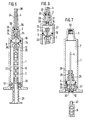
- einen Längsschnitt durch eine erste Ausführungsform der Spritze;
- Fig. 2
- einen Schnitt durch den Fortsatz am Kolben entlang der Linie II-II in Fig. 1;
- Fig. 3
- einen Längsschnitt durch das vordere Teil der Spritze nach einer anderen Ausführungsform;
- Fig. 4
- einen Längsschnitt durch eine andere Kolbenvariante;
- Fig. 5
- einen Längsschnitt durch eine weitere Ausführungsform der Spritze;
- Fig. 6
- einen Längsschnitt durch den vorderen Teil der Spritze nach Fig. 5 in vergrößerter Wiedergabe und mit teilweise zurückgezogenem Kolben und
- Fig. 7
- einen Längsschnitt durch die Spritze nach Fig. 5 mit vollständig zurückgezogenem Kolben und abgeschraubter, nur teilweise dargestellter Kolbenstange.
- Fig. 1
- a longitudinal section through a first embodiment of the syringe;
- Fig. 2
- a section through the extension on the piston along the line II-II in Fig. 1;
- Fig. 3
- a longitudinal section through the front part of the syringe according to another embodiment;
- Fig. 4
- a longitudinal section through another piston variant;
- Fig. 5
- a longitudinal section through a further embodiment of the syringe;
- Fig. 6
- a longitudinal section through the front part of the syringe of FIG. 5 in an enlarged representation and with the piston partially retracted and
- Fig. 7
- a longitudinal section through the syringe of FIG. 5 with the piston fully retracted and unscrewed, only partially shown piston rod.
Gemäß Fig. 1 weist die Spritze ein Spritzengehäuse 1 auf, in dem sich eine zylindrische Kammer 2 befindet. Das Spritzengehäuse 1 ist an seinem vorderen Ende mit einer Verjüngung 3 versehen, durch die die Injektionsnadel 4 gesteckt ist, die sich in die Kammer 2 erstreckt.1, the syringe has a
In der Kammer 2 ist ein Kolben 5 verschiebbar geführt, der an seiner Rückseite mit einer Kolbenstange 6 versehen ist, die sich aus dem hinteren Ende des Spritzengehäuses 1 nach außen erstreckt.In the
Wenn sich der Kolben 2 zwischen seinen beiden Endstellungen am vorderen bzw. hinteren Ende der Kammer 2 befindet, trennt er die Kammer 2 in einen ersten, vorderen, der Nadel 4 zugewandten Abschnitt 7, in dem sich die Injektionsflüssigkeit befindet, und einen zweiten, hinteren Abschnitt 8, durch den sich die Kolbenstange 6 erstreckt und die keine Flüssigkeit enthält, also mit Luft gefüllt ist.If the
An seiner der Nadel 4 bzw. dem vorderen Kammerabschnitt zugewandten Stirnseite 9 ist der Kolben 5 mit einer Öffnung 10 versehen, die durch einen sich in Axialrichtung erstreckenden Längskanal 11 gebildet wird, der sich in einen Fortsatz 12 an der Rückseite des Kolbens 5 hinein erstreckt.On its
Gemäß Fig. 2 ist der Fortsatz 12 im Querschnitt kreuzförmig ausgebildet, wobei der Durchmesser des Längskanals 11 größer ist als die Dicke der Arme des Kreuzes, so daß jeweils seitliche Längsöffnungen 13 in den Ecken zwischen zwei benachbarten Armen gebildet werden, welche mit dem hinteren Abschnitt 8 der Kammer 2, also mit der darin enthaltenen Luft kommunizieren.2, the
Die Öffnung 10 an der Stirnseite 9 des Kolbens ist durch eine Membran 14 verschlossen. Das hintere Ende der Nadel 4, welches in die Kammer 2 bzw. den vorderen Abschnitt 7 hineinragt, ist mit einer Spitze versehen. Dadurch wird ein spitzes Element 15 am vorderen Boden 16 der Kammer 2 gebildet. Das spitze Element 15 liegt dabei in Bewegungsrichtung des Kolbens 2 der Öffnung 10 genau gegenüber, d.h., gemäß Fig. 1 liegen sowohl die Öffnung 10 wie das spitze Element 15 in der Längsmittelachse der Spritze.The
Wenn der Kolben 5 außer der in Fig. 1 gezeigten Stellung gegen den Boden 16 der Kammer 2 bewegt wird, durchsticht das spitze hintere Ende 15 der Nadel 4 die Membran 14, so daß die Öffnung 10 freigegeben wird. Damit kommuniziert der vordere Abschnitt 7 mit dem hinteren Abschnitt 8 der Kammer, d.h., der Kolben 2 wird wirkungslos. Die Spritze ist damit unbrauchbar, also ein zweites Mal nicht verwendbar.When the
Bei der Ausführungsform nach Fig. 1 besteht der Kolben 5 aus einem ersten ringförmigen Abschnitt 17 mit einer sich nach hinten erweiternden Ringöffnung und einem sich von der Kolbenstange 6 in dieRingöffnung des ringförmigen Abschnitts 17 hineinerstreckenden zweiten, sich nach vorne verjüngenden Abschnitt 18, an dem der Fortsatz 12 mit den Längsöffnungen 13 angeordnet ist. Die Membran 14 ist kappenförmig ausgebildet und über den zweiten Abschnitt 18 gestülpt, also zwischen den beiden Abschnitten 17 und 18 eingeklemmt. Am Umfang des Kolbens 5 bzw. des ersten Abschnitts 17 ist in einer Nut ein O-Ring 19 o.dgl. Dichtung angeordnet.In the embodiment according to FIG. 1, the
Bei der Ausführungsform nach Fig. 3 ist die Membran 14 als Scheibe ausgebildet, wobei sie auf dem Kolben 2 aufliegt und dessen gesamte Stirnseite 9 bedeckt. Nach Fig. 3 erstrecken sich von dem Längskanal 11 radiale Bohrungen 20 in die Kammer 2 bzw. in den hinteren Kammerabschnitt 8. Bei dieser Ausführungsform kann die Kolbenstange 6 also z.B. zylindrisch ausgebildet und der Längskanal 11 durch eine Längsbohrung in der Kolbenstange 6 gebildet sein.In the embodiment according to FIG. 3, the
Weiterhin wird bei der Ausführungsform nach Fig. 3 das spitze Element 15, das die Membran 14 durchsticht, durch einen am Boden 14 der Kammer 2 vorgesehenen Vorsprung gebildet, der der Öffnung 10 gegenüberliegt, also wie diese in der Längsmittelachse der Spritze liegt. Die Injektionsnadel 4 ist bei dieser Ausführungsform exzentrisch angeordnet.Furthermore, in the embodiment according to FIG. 3, the pointed
Bei der Ausführungsform nach Fig. 4 ist die Membran 14 in einer Ausnehmung an der Stirnseite 9 des Kolbens 5 befestigt.In the embodiment according to FIG. 4, the
Gemäß Fig. 1 weist die Kolbenstange 6, die sich an den Fortsatz 12 anschließt, einen Längskanal 21 auf, der am hinteren Ende der Kolbenstange 6 ins Freie mündet. Die Kolbenstange 6 ist ferner mit radialen Öffnungen 22 versehen, so daß der hintere Abschnitt 8 der Kammer 2 mit der Umgebung kommuniziert. Damit kommuniziert nach dem Durchstechen der Membran 14 der vordere Abschnitt 7 der Kammer 2 ebenfalls mit der Umgebung, so daß die Spritze unbrauchbar ist.1, the
An ihrem hinteren, freien Ende weist die Kolbenstange 6 ring- oder schraubenförmige Verdickungen 28 auf, um eine rutschfeste Fläche zu bilden, die das Füllen der Spritze sicherer macht.At its rear, free end, the
Die Injektionsnadel 4 ist an dem Spritzengehäuse 1 feststehend oder herausschiebbar befestigt. Sie ist durch eine Abdeckung oder Kappe 24 geschützt, die sich bis zum vorderen Ende des Spritzengehäuses 1 erstreckt.The injection needle 4 is fixed to the
An dem von der Nadel 4 abgewandten Ende weist das Spritzengehäuse 4 an der Innenseite eine Ringnut auf, in der eine Buchse 25 angeordnet ist, welche als Führung und Dichtung für die Kolbenstange 6 sowie als Herausziehsicherung für den Kolben 5 dient. Damit kann der Kolben 5 nicht aus dem Spritzengehäuse 1 gezogen werden, so daß auch das Spritzengehäuse 1 nicht erneut verwendet werden kann, also mit einem neuen Kolben.At the end facing away from the needle 4, the syringe housing 4 has an annular groove on the inside, in which a
Bei der erfindungsgemäßen Spritze schließt der Kolben 5 mit der durch die Membran 14 verschlossenen Öffnung 10 den vorderen Abschnitt 7 vom hinteren Abschnitt 8 der Kammer 2 ab, so daß die Flüssigkeit, die gespritzt werden soll, wie bei einer herkömmlichen Spritze eingesaugt werden kann. Nachdem die Spritze gefüllt ist, wird sie dem Patienten, wie üblich, verabreicht. Wenn der Kolben 5 den Boden 16 der Kammer 2 erreicht, durchsticht das spitze Element 15 die Membran 14 an der Öffnung 10. Damit ist es nicht mehr möglich, die Spritze nachzufüllen. D.h., sie ist unbrauchbar, so daß Risiken vermieden sind, die mit einer zweitmaligen Verwendung der Spritze verbunden sind, wie beispielsweise die Übertragung von Krankheiten, wie Aids, Hepatitis, usw..In the syringe according to the invention, the
Bei der Ausführungsform nach Fig. 5 bis 7 weist der Kolben 5 an seiner Stirnseite 9 einen Zapfen 25 auf, durch den sich der Längskanal 11 erstreckt. Die Öffnung 10 am vorderen Ende des Längskanals 11 ist dabei wiederum durch eine Membran 11 verschlossen, die jedoch bei dieser Ausführungsform einstückig mit dem Zapfen 25 bzw. dem Kolben 5 ausgebildet ist.In the embodiment according to FIGS. 5 to 7, the
Auch bei dieser Ausführungsform ist die Nadel 4 durch eine hülsenförmige Abdeckung 24 anfänglich geschützt, die jedoch einstückig mit dem Spritzengehäuse 1 ausgebildet ist. Die Abdeckung 24 kann durch Abbrechen an der ringförmigen Abschwächung 26 an ihrer Basis abgezogen werden.In this embodiment, too, the needle 4 is initially protected by a sleeve-shaped
Der Zapfen 25 am Kolben 5 ist mit einem Gewinde 27 versehen und kann damit in eine Buchse 28 geschraubt werden, die in der als Hals ausgebildeten Verjüngung 3 am vorderen Ende des Spritzengehäuses 1 angeordnet ist. Dazu ist die Buchse 28 mit einem Außengewinde 29 versehen, das in ein entsprechendes Innengewinde im Halsabschnitt 3 eingreift. Das Außengewinde 27 an dem Zapfen 25 und das Außengewinde 29 an der Buchse 28 verlaufen in Gegenrichtung; durch Drehung der Kolbenstange 6 und damit des Zapfens 25 ist der Zapfen 25 mit der im Halsabschnitt 3 angeordneten Buchse 28 kuppelbar, die ihrerseits mit dem Halsabschnitt 3 durch Drehung in gleicher Drehrichtung vom Halsabschnitt 3 abgeschraubt wird.The
Das Gewinde 27 am Zapfen 25 kann in ein Innengewinde in der Buchse 28 eingreifen. Statt eines Innengewindes kann die Buchse 28 ringförmige Rillen 31 aufweisen, um den Zapfen 25 durch Axialdruck in der Buchse 28 festzuklemmen.The
Zwischen der Buchse 28 und dem vorderen Ende des Halsabschnitts 3 des Spritzengehäuses 1 ist eine scheibenförmige Dichtung 30 angebracht.A disk-shaped
Um die Gefahr einer Ansteckung durch einen zufälligen Stich oder Kratzer auszuschalten, wird nach Verabreichung der Injektion durch den Verabreichenden die Kolbenstange 6 so gedreht, daß der Zapfen 25 an der Stirnseite 9 des Kolbens 5 in die rückseitige Aufnahme der Buchse 28 mit den Rillen 31 geschraubt wird. Bei Fortsetzung der Drehung wird die Buchse 28 vom Halsabschnitt 3 des Spritzengehäuses 1 abgeschraubt, so daß beim Zurückziehen der Kolbenstange 6 die in der Buchse 28 befestigte Nadel 4 in die Kammer 2 hinein bewegt wird. Wenn die Kolbenstange 6 in ihre zurückgezogene Position bewegt worden ist, greift ferner der ringförmige Vorsprung 36 an der Buchse 37 in die Nut oder Einschnürung 34 an dem rückwärtigen Fortsatz 12 des Kolbens 5 ein, wodurch dieser in dieser Lage festgeklemmt wird.In order to eliminate the risk of contagion from an accidental puncture or scratch, after administration of the injection by the person administering it, the
Dadurch wird die Nadel 4 in der Kammer 2, also im Innern des Spritzengehäuses 1 festgehalten, so daß sie von außen nicht mehr zugänglich ist. Die scheibenförmige Dichtung 30 schließt ihrerseits aufgrund ihrer elastischen Beschaffenheit automatisch die Öffnung, durch die sich zuvor die Nadel 4 erstreckte. Auf diese Weise ist die Kammer 2 mit der darin angeordneten Nadel 4 hermetisch gegenüber der Umgebung abgeschlossen.As a result, the needle 4 is held in the
Wenn die Kupplung des Kolbens 5 mit der Buchse 28 durch die schrägen ringförmigen Rillen 31 erfolgt, tritt die Kupplung automatisch am Ende der Verabreichung der Spritze ein, d.h., wenn der Zapfen 25 die Buchse 28 erreicht. Nachdem die Nadel 4, wie vorstehend angegeben, durch Zurückziehen der Kolbenstange 6 in das Spritzengehäuse hinein bewegt worden ist, kann die Kolbenstange 6 durch Aufschrauben der Gewinde 32 und 33 von dem Kolben 6 abgeschraubt werden. Damit benötigt die weggeworfene Spritze weniger Platz. Darüber hinaus kann kein ungewollter Axialschub erfolgen, durch den im Extremfall die Nadel 4 wieder herausbefördert werden würde. Ebenfalls aus Gründen der Sicherheit und zur Verringerung des Platzbedarfes erfolgt der Verkauf der Spritze vorteilhafterweise mit abgeschraubter Kolbenstange 6.If the coupling of the
Wenn die Spritze für Impfungen verwendet werden soll - in diesem Fall ist es üblich, daß das Mittel, das gespritzt werden soll, ursprünglich in der Spritze enthalten ist - ist an dem Ende der Abdeckung 24 ein Stopfen 38 befestigt, um zu verhindern, daß das Impfmittel durch die Nadel 4 austritt.When the syringe is to be used for vaccinations - in this case it is common for the agent to be injected to be originally contained in the syringe - a
Die Nadel 4 weist am rückseitigen Ende, an der sich das spitze Element 15 befindet, eine seitliche Öffnung 39 auf, die einen zweiten Ausgang für die zu spritzende Flüssigkeit bildet, und insbesondere dann erforderlich ist, wenn das spitze Element 15 in die Membran 14 eingedrungen ist, um den Rest der Flüssigkeit zu verabreichen. D.h., die Öffnung 39 gewährleistet den Flüssigkeitsaustritt bis zum Ende der Verabreichung. insbesondere dann erforderlich ist, wenn das spitze Element 15 in die Membran 14 eingedrungen ist, um den Rest der Flüssigkeit zu verabreichen. D.h., die Öffnung 39 gewährleistet den Flüssigkeitsaustritt bis zum Ende der Verabreichung.The needle 4 has at the rear end, at which the pointed
Claims (19)
Applications Claiming Priority (2)
| Application Number | Priority Date | Filing Date | Title |
|---|---|---|---|
| ES9100283A ES2031754A6 (en) | 1991-02-04 | 1991-02-04 | Self destructive disposable syringe. |
| ES9100283 | 1991-02-04 |
Publications (1)
| Publication Number | Publication Date |
|---|---|
| EP0498376A1 true EP0498376A1 (en) | 1992-08-12 |
Family
ID=8271064
Family Applications (1)
| Application Number | Title | Priority Date | Filing Date |
|---|---|---|---|
| EP92101835A Withdrawn EP0498376A1 (en) | 1991-02-04 | 1992-02-04 | Self destructive disposable syringe |
Country Status (2)
| Country | Link |
|---|---|
| EP (1) | EP0498376A1 (en) |
| ES (1) | ES2031754A6 (en) |
Cited By (9)
| Publication number | Priority date | Publication date | Assignee | Title |
|---|---|---|---|---|
| WO1999048543A2 (en) * | 1998-03-20 | 1999-09-30 | Mauro Ghigo | Safety syringe |
| EP1281412A1 (en) * | 2001-03-07 | 2003-02-05 | Eurochina Farma S.L. | Non reusable syringe |
| WO2006047810A1 (en) * | 2004-11-04 | 2006-05-11 | Global Medisafe Holdings Pty Limited | Exchange needle retractable safety syringe |
| WO2007028190A1 (en) * | 2005-09-06 | 2007-03-15 | Global Medisafe Holdings Limited | Single use safety syringe having a retractable needle |
| EP1894589A1 (en) * | 2005-06-09 | 2008-03-05 | Ying, Jishui | Self-destructed disposable syringe |
| US7806860B2 (en) | 2005-11-15 | 2010-10-05 | Global Medisafe Holdings Limited | Safety syringe with plunger locking means |
| CN103372250A (en) * | 2012-04-27 | 2013-10-30 | 张林锋 | Back-pulling type safety self-locking self-destroying syringe |
| CN106955399A (en) * | 2016-01-08 | 2017-07-18 | 吕文进 | Safety injector |
| CN109758214A (en) * | 2019-01-18 | 2019-05-17 | 皖南医学院第一附属医院(皖南医学院弋矶山医院) | Visual anesthetic puncture drill autofeeder |
Families Citing this family (3)
| Publication number | Priority date | Publication date | Assignee | Title |
|---|---|---|---|---|
| ES2117569B1 (en) * | 1996-05-23 | 1999-03-16 | Redrado Fernando Melero | SINGLE USE SYRINGE. |
| WO1997044076A1 (en) * | 1996-05-23 | 1997-11-27 | Fernando Melero Redrado | Disposable syringe |
| ES2133099B1 (en) * | 1997-05-22 | 2000-04-01 | Redrado Fernando Melero | IMPROVEMENTS IN SINGLE USE SYRINGES. |
Citations (9)
| Publication number | Priority date | Publication date | Assignee | Title |
|---|---|---|---|---|
| FR2298340A1 (en) * | 1975-01-24 | 1976-08-20 | Blanie Paul | Disposable hypodermic syringe - has formation in cylinder to render plunger ineffective after one depression |
| US4687467A (en) * | 1986-06-11 | 1987-08-18 | C.T.F. Research Company | One-time use medical syringe invention |
| FR2606643A1 (en) * | 1986-11-17 | 1988-05-20 | Congio Gerard | Syringe which is rendered inoperative after the first use |
| WO1989009075A1 (en) * | 1988-03-22 | 1989-10-05 | Davsa Seventy-Fifth Pty. Ltd. | Hypodermic needle retractor |
| NL8801072A (en) * | 1988-04-26 | 1989-11-16 | Willem Jozef Hubertus Rutten | Syringe with sliding needle - has hooked rear needle end puncturing plunger at end of forward stroke |
| US4888002A (en) * | 1988-08-30 | 1989-12-19 | Braginetz Paul A | Disposable shield medical syringe |
| EP0347742A1 (en) * | 1988-06-23 | 1989-12-27 | Aldo Venturini | Disposable safety syringe |
| WO1990011790A1 (en) * | 1989-04-04 | 1990-10-18 | Keith Herd Youne Mcmahon | Disposable syringe |
| US4994034A (en) * | 1989-07-11 | 1991-02-19 | Botich Michael J | Retractable needle hypodermic syringe system |
-
1991
- 1991-02-04 ES ES9100283A patent/ES2031754A6/en not_active Expired - Lifetime
-
1992
- 1992-02-04 EP EP92101835A patent/EP0498376A1/en not_active Withdrawn
Patent Citations (9)
| Publication number | Priority date | Publication date | Assignee | Title |
|---|---|---|---|---|
| FR2298340A1 (en) * | 1975-01-24 | 1976-08-20 | Blanie Paul | Disposable hypodermic syringe - has formation in cylinder to render plunger ineffective after one depression |
| US4687467A (en) * | 1986-06-11 | 1987-08-18 | C.T.F. Research Company | One-time use medical syringe invention |
| FR2606643A1 (en) * | 1986-11-17 | 1988-05-20 | Congio Gerard | Syringe which is rendered inoperative after the first use |
| WO1989009075A1 (en) * | 1988-03-22 | 1989-10-05 | Davsa Seventy-Fifth Pty. Ltd. | Hypodermic needle retractor |
| NL8801072A (en) * | 1988-04-26 | 1989-11-16 | Willem Jozef Hubertus Rutten | Syringe with sliding needle - has hooked rear needle end puncturing plunger at end of forward stroke |
| EP0347742A1 (en) * | 1988-06-23 | 1989-12-27 | Aldo Venturini | Disposable safety syringe |
| US4888002A (en) * | 1988-08-30 | 1989-12-19 | Braginetz Paul A | Disposable shield medical syringe |
| WO1990011790A1 (en) * | 1989-04-04 | 1990-10-18 | Keith Herd Youne Mcmahon | Disposable syringe |
| US4994034A (en) * | 1989-07-11 | 1991-02-19 | Botich Michael J | Retractable needle hypodermic syringe system |
Cited By (15)
| Publication number | Priority date | Publication date | Assignee | Title |
|---|---|---|---|---|
| WO1999048543A2 (en) * | 1998-03-20 | 1999-09-30 | Mauro Ghigo | Safety syringe |
| WO1999048543A3 (en) * | 1998-03-20 | 1999-11-11 | Mauro Ghigo | Safety syringe |
| EP1281412A1 (en) * | 2001-03-07 | 2003-02-05 | Eurochina Farma S.L. | Non reusable syringe |
| WO2006047810A1 (en) * | 2004-11-04 | 2006-05-11 | Global Medisafe Holdings Pty Limited | Exchange needle retractable safety syringe |
| EP1894589A4 (en) * | 2005-06-09 | 2012-01-11 | Ying Jishui | Self-destructed disposable syringe |
| EP1894589A1 (en) * | 2005-06-09 | 2008-03-05 | Ying, Jishui | Self-destructed disposable syringe |
| EA013279B1 (en) * | 2005-09-06 | 2010-04-30 | Глобал Медисэйф Холдингз Лимитед | Single use safety syringe having a retractable needle |
| WO2007028190A1 (en) * | 2005-09-06 | 2007-03-15 | Global Medisafe Holdings Limited | Single use safety syringe having a retractable needle |
| US7806860B2 (en) | 2005-11-15 | 2010-10-05 | Global Medisafe Holdings Limited | Safety syringe with plunger locking means |
| CN103372250A (en) * | 2012-04-27 | 2013-10-30 | 张林锋 | Back-pulling type safety self-locking self-destroying syringe |
| CN103372250B (en) * | 2012-04-27 | 2015-06-17 | 温州市贝普科技有限公司 | Back-pulling type safety self-locking self-destroying syringe |
| CN106955399A (en) * | 2016-01-08 | 2017-07-18 | 吕文进 | Safety injector |
| CN106955399B (en) * | 2016-01-08 | 2023-03-24 | 吕文进 | Safety syringe |
| CN109758214A (en) * | 2019-01-18 | 2019-05-17 | 皖南医学院第一附属医院(皖南医学院弋矶山医院) | Visual anesthetic puncture drill autofeeder |
| CN109758214B (en) * | 2019-01-18 | 2022-06-10 | 皖南医学院第一附属医院(皖南医学院弋矶山医院) | Visual anesthesia puncture automatic propelling device |
Also Published As
| Publication number | Publication date |
|---|---|
| ES2031754A6 (en) | 1992-12-16 |
Similar Documents
| Publication | Publication Date | Title |
|---|---|---|
| DE3823266C2 (en) | Spray ampoule | |
| DE69726531T2 (en) | Lockable protective sleeve for pre-filled syringe | |
| DE60020479T2 (en) | Syringe with retractable needle | |
| DE69930393T2 (en) | MEDICAL SECURITY SYRINGE WITH RETRACTABLE NEEDLE | |
| EP0707859B1 (en) | Containers for storage and administration of preparations suited for injection, infusion or diagnostic purpose | |
| DE10009814B4 (en) | Disposable injector | |
| EP0830868B1 (en) | Prefilled syringe for medical purpose | |
| DE60011386T2 (en) | Injection syringe for single use | |
| EP0917882B1 (en) | Syringe particularly a prefilled syringe or ampoule | |
| EP0581788B1 (en) | Injection device | |
| DE69816965T2 (en) | LOCKABLE PROTECTIVE SHIELD ARRANGEMENT FOR A PRE-FILLABLE SYRINGE | |
| EP1566194B1 (en) | Syringe, in particular for medical applications | |
| EP0373321B1 (en) | Reusable injection device for the delivery of a preselected dose | |
| EP0412283A1 (en) | Syringe cylinder for medical use | |
| DE2854527A1 (en) | INJECTION SYRINGE | |
| DE2445535A1 (en) | INJECTION SYRINGE | |
| DE3916101A1 (en) | SYRINGE FOR MEDICAL PURPOSES | |
| CH691031A5 (en) | Two-part device for the administration of drugs. | |
| DE102004009918A1 (en) | Arrangement for storing, transporting and applying a preferably medical liquid | |
| DE102005043805A1 (en) | Positioning device for e.g. injecting pen, has needle guide/cover with positioning unit to guide or position needle, or protective caps or needle holder, so that needle is guided and/or positioned relative to preset entry position by unit | |
| EP0498376A1 (en) | Self destructive disposable syringe | |
| DE2259825A1 (en) | INJECTION SYRINGE | |
| DE60032171T2 (en) | IMPROVEMENTS RELATING TO SUBCUTANEJECTION SYRINGES | |
| WO2010085903A1 (en) | Administering device comprising a holding element for a fluid receptacle | |
| DE10252220B3 (en) | Medical syringe |
Legal Events
| Date | Code | Title | Description |
|---|---|---|---|
| PUAI | Public reference made under article 153(3) epc to a published international application that has entered the european phase |
Free format text: ORIGINAL CODE: 0009012 |
|
| AK | Designated contracting states |
Kind code of ref document: A1 Designated state(s): AT CH DE FR GB IT LI NL SE |
|
| 17P | Request for examination filed |
Effective date: 19930426 |
|
| STAA | Information on the status of an ep patent application or granted ep patent |
Free format text: STATUS: THE APPLICATION IS DEEMED TO BE WITHDRAWN |
|
| 18D | Application deemed to be withdrawn |
Effective date: 19940901 |