EP0493961A2 - Method of storing information - Google Patents
Method of storing information Download PDFInfo
- Publication number
- EP0493961A2 EP0493961A2 EP91311981A EP91311981A EP0493961A2 EP 0493961 A2 EP0493961 A2 EP 0493961A2 EP 91311981 A EP91311981 A EP 91311981A EP 91311981 A EP91311981 A EP 91311981A EP 0493961 A2 EP0493961 A2 EP 0493961A2
- Authority
- EP
- European Patent Office
- Prior art keywords
- image
- taggant
- marking material
- marking
- predetermined
- Prior art date
- Legal status (The legal status is an assumption and is not a legal conclusion. Google has not performed a legal analysis and makes no representation as to the accuracy of the status listed.)
- Granted
Links
Images


Classifications
-
- H—ELECTRICITY
- H04—ELECTRIC COMMUNICATION TECHNIQUE
- H04N—PICTORIAL COMMUNICATION, e.g. TELEVISION
- H04N1/00—Scanning, transmission or reproduction of documents or the like, e.g. facsimile transmission; Details thereof
- H04N1/00838—Preventing unauthorised reproduction
- H04N1/0084—Determining the necessity for prevention
- H04N1/00843—Determining the necessity for prevention based on recognising a copy prohibited original, e.g. a banknote
- H04N1/00846—Determining the necessity for prevention based on recognising a copy prohibited original, e.g. a banknote based on detection of a dedicated indication, e.g. marks or the like
-
- G—PHYSICS
- G03—PHOTOGRAPHY; CINEMATOGRAPHY; ANALOGOUS TECHNIQUES USING WAVES OTHER THAN OPTICAL WAVES; ELECTROGRAPHY; HOLOGRAPHY
- G03G—ELECTROGRAPHY; ELECTROPHOTOGRAPHY; MAGNETOGRAPHY
- G03G15/00—Apparatus for electrographic processes using a charge pattern
- G03G15/50—Machine control of apparatus for electrographic processes using a charge pattern, e.g. regulating differents parts of the machine, multimode copiers, microprocessor control
- G03G15/5066—Machine control of apparatus for electrographic processes using a charge pattern, e.g. regulating differents parts of the machine, multimode copiers, microprocessor control by using information from an external support, e.g. magnetic card
- G03G15/507—Machine control of apparatus for electrographic processes using a charge pattern, e.g. regulating differents parts of the machine, multimode copiers, microprocessor control by using information from an external support, e.g. magnetic card being interleaved with the original or directly written on he original, e.g. using a control sheet
-
- G—PHYSICS
- G03—PHOTOGRAPHY; CINEMATOGRAPHY; ANALOGOUS TECHNIQUES USING WAVES OTHER THAN OPTICAL WAVES; ELECTROGRAPHY; HOLOGRAPHY
- G03G—ELECTROGRAPHY; ELECTROPHOTOGRAPHY; MAGNETOGRAPHY
- G03G21/00—Arrangements not provided for by groups G03G13/00 - G03G19/00, e.g. cleaning, elimination of residual charge
- G03G21/04—Preventing copies being made of an original
- G03G21/046—Preventing copies being made of an original by discriminating a special original, e.g. a bank note
-
- H—ELECTRICITY
- H04—ELECTRIC COMMUNICATION TECHNIQUE
- H04N—PICTORIAL COMMUNICATION, e.g. TELEVISION
- H04N1/00—Scanning, transmission or reproduction of documents or the like, e.g. facsimile transmission; Details thereof
- H04N1/00838—Preventing unauthorised reproduction
- H04N1/00856—Preventive measures
- H04N1/00875—Inhibiting reproduction, e.g. by disabling reading or reproduction apparatus
-
- H—ELECTRICITY
- H04—ELECTRIC COMMUNICATION TECHNIQUE
- H04N—PICTORIAL COMMUNICATION, e.g. TELEVISION
- H04N1/00—Scanning, transmission or reproduction of documents or the like, e.g. facsimile transmission; Details thereof
- H04N1/38—Circuits or arrangements for blanking or otherwise eliminating unwanted parts of pictures
-
- H—ELECTRICITY
- H04—ELECTRIC COMMUNICATION TECHNIQUE
- H04N—PICTORIAL COMMUNICATION, e.g. TELEVISION
- H04N2201/00—Indexing scheme relating to scanning, transmission or reproduction of documents or the like, and to details thereof
- H04N2201/32—Circuits or arrangements for control or supervision between transmitter and receiver or between image input and image output device, e.g. between a still-image camera and its memory or between a still-image camera and a printer device
- H04N2201/3201—Display, printing, storage or transmission of additional information, e.g. ID code, date and time or title
- H04N2201/3225—Display, printing, storage or transmission of additional information, e.g. ID code, date and time or title of data relating to an image, a page or a document
- H04N2201/3233—Display, printing, storage or transmission of additional information, e.g. ID code, date and time or title of data relating to an image, a page or a document of authentication information, e.g. digital signature, watermark
-
- H—ELECTRICITY
- H04—ELECTRIC COMMUNICATION TECHNIQUE
- H04N—PICTORIAL COMMUNICATION, e.g. TELEVISION
- H04N2201/00—Indexing scheme relating to scanning, transmission or reproduction of documents or the like, and to details thereof
- H04N2201/32—Circuits or arrangements for control or supervision between transmitter and receiver or between image input and image output device, e.g. between a still-image camera and its memory or between a still-image camera and a printer device
- H04N2201/3201—Display, printing, storage or transmission of additional information, e.g. ID code, date and time or title
- H04N2201/3225—Display, printing, storage or transmission of additional information, e.g. ID code, date and time or title of data relating to an image, a page or a document
- H04N2201/3242—Display, printing, storage or transmission of additional information, e.g. ID code, date and time or title of data relating to an image, a page or a document of processing required or performed, e.g. for reproduction or before recording
-
- H—ELECTRICITY
- H04—ELECTRIC COMMUNICATION TECHNIQUE
- H04N—PICTORIAL COMMUNICATION, e.g. TELEVISION
- H04N2201/00—Indexing scheme relating to scanning, transmission or reproduction of documents or the like, and to details thereof
- H04N2201/32—Circuits or arrangements for control or supervision between transmitter and receiver or between image input and image output device, e.g. between a still-image camera and its memory or between a still-image camera and a printer device
- H04N2201/3201—Display, printing, storage or transmission of additional information, e.g. ID code, date and time or title
- H04N2201/3269—Display, printing, storage or transmission of additional information, e.g. ID code, date and time or title of machine readable codes or marks, e.g. bar codes or glyphs
- H04N2201/327—Display, printing, storage or transmission of additional information, e.g. ID code, date and time or title of machine readable codes or marks, e.g. bar codes or glyphs which are undetectable to the naked eye, e.g. embedded codes
-
- H—ELECTRICITY
- H04—ELECTRIC COMMUNICATION TECHNIQUE
- H04N—PICTORIAL COMMUNICATION, e.g. TELEVISION
- H04N2201/00—Indexing scheme relating to scanning, transmission or reproduction of documents or the like, and to details thereof
- H04N2201/32—Circuits or arrangements for control or supervision between transmitter and receiver or between image input and image output device, e.g. between a still-image camera and its memory or between a still-image camera and a printer device
- H04N2201/3201—Display, printing, storage or transmission of additional information, e.g. ID code, date and time or title
- H04N2201/3271—Printing or stamping
Definitions
- the present invention relates generally to a method of storing information and more particularly, but not exclusively, to a process for controlling a reproduction systen and to that reproduction system.
- the invention relates also more particularly, but not exclusively, to a method of producing an image and to a marking material.
- An electronic reprographic printing system is a system wherein an image on an original document is scanned and transformed into electronic image signals within the system's memory. Those signals are thereafter processed and the image is reproduced by display and/or printing on a substrate such as paper, transparency film, or the like.
- This system differs significantly from a conventional xerographic system which produces an image by a light coupling process.
- An electronic reprographic system is capable of performing a multiplicity of functions related to the images processed within the system.
- a printing system such as an electronic reprographic system
- several devices usually make up the total system, with separate devices or components providing the functions of scanning, processing, printing, and finishing (e.g., stapling, binding, etc.).
- the system includes a controller which provides for the overall monitoring and integrating of the performance of the aforementioned functions.
- the materials employed to "fix” the images being manipulated and processed in the system are substantially the same as those used in other copying or printing systems, and include the color marking materials, generally toners or ink-jet inks.
- the term "color” includes black and other colors, except where otherwise clear from the context.
- the present invention provides a process for controlling a reproduction system, characterised by scanning an image to detect at least one taggant in at least one marking material forming said image, comparing each detected taggant with at least one known taggant associated with at least one known type of marking material, and issuing instructions determined by results of said comparison to said reproduction system.
- said scanning step comprises scanning said image for each of a plurality of taggants. Conveniently the or each taggant is detected as a function of an emitted or reflected light wavelength.
- said marking material contains a colorant which reflects or emits light in one portion of the light spectrum, and said taggant reflects or emits light in a distinguishable portion of the light spectrum.
- Said distinguishable portion of the light spectrum may be a very narrow wavelength band within said one portion of the light spectrum.
- Said one portion of the light spectrum may not overlap with the distinguishable portion of the light spectrum or said one portion of the light spectrum is one member selected from the group consisting of ultraviolet light and infrared light, and said, distinguishable portion of the light spectrum is the other member of said group.
- marking material characterised in that said marking material comprises a taggant and a colorant, said marking material being specially adapted for use in a mechanical or electromechanical printing process.
- Inks generally contain a dye.
- any effective dye such as one of the direct dyes or the acid dyes, can be selected as the colorant, provided that it is compatible with the other ink components and is soluble in the liquid vehicle.
- suitable dyes include anthraquinones, monoazo dyes, disazo dyes, phthalocyanines, aza(18)annulenes, and formazan copper complexes.
- biocides such as Dowicil 150, 200, and 75, benzoate salts, sorbate salts, and the like, present in an amount of from about 0.0001 to about 4 percent by weight, and preferably from about 0.01 to about 2.0 percent by weight
- humectants and penetration control additives such as ethylene glycol, diethyleneglycol, N-methylpyrolidinone, propylene glycol, hydroxyethers, ethers, amides, sulfoxides, ketones, lactones, esters, alcohols, butyl carbitol, benzyl alcohol, cyclohexylpyrrolidinone, 1,2-hexanediol, and the like, present in an amount of from 0 to about 50 percent by weight, and preferably from about 5 to about 40 percent by weight
- pH controlling agents such as acids or bases, phosphate salts, carboxylate salts, sulfite salts, amine salts and the like, present in an amount of from
- a taggant may be composed of a material which fluoresces or reflects light of visible or, preferably, "invisible" wavelengths. However, it should not interfere with the color of the marking material in which it is utilized within the image. For example, in a visible ink, the taggant would preferably fluoresce or reflect in an invisible (IR or UV) wavelength; for an "invisible” ink which reflects UV light, the taggant would preferably reflect or fluoresce in a separate part of the UV spectrum or in the IR spectrum. In a less preferred embodiment, the taggant would fluoresce or reflect light in a very narrow wavelength band within the same portion of the spectrum more broadly emitted or reflected by a colorant in the marking material. This would create a "peak" on the spectral response of the colorant which would be recognizable by a scanner, but which would not substantially interfere with perception of the image.
- any fluorescent dye may be selected as a taggant in inks or toners of the present invention.
- Exemplary taggant dyes for inks include, for example, 4,4'-bis(triazin-2-ylamino)stilbene-2,2'-disulfonic acids, 2-(stilben-4-yl)naphthotriazoles, 2-(4-phenylstilben-4-yl) benzoxazoles, 4,4-bis(triazo-2yl) stilbene-2,2'-disulfonic acids, 1,4-bis(styryl)biphenyls, 1,3-diphenyl-2- pyrazolines, bis(benzazol-2-yl) derivatives, 3-phenyl-7- (triazin-2-yl)coumarins, carbostyrils, naphthalimides, 3,7-diaminodibenzothiophen-2,8-disulfonic acid-5,5-dioxide and the like.
- the output light for each taggant can be detected and the presence or absence of taggant can be determined by equipment well known in the art. This information can then be processed further to perform, for example, the special functions of the printing system described herein.
- the necessary algorithms can readily be prepared by those of ordinary skill in the art without undue experimentation. They will generally include comparing the detected taggant wavelength to a "table" containing a plurality of taggant wavelengths and associated information maintained in the system memory.
- the "associated information" may include the identity of toners, inks or marking films containing the detected taggant(s) and the spectral response of colorants in those toners or inks; various types of instructional information for the reproduction system; or the like.
- the information accessed through use of the table permits precisely tailored control of the image reproduction.
- Many printing systems are capable of performing various specialized functions between the scanning and printing function such as color enhancement, correction and translation, document "dry-cleaning", and a number of security applications. These functions may be either enabled or controlled by the information made available by the present invention.
- a document entry slot 46 provides access to the document feed belt 42 between tray 37 and platen 20 through which individual documents may be inserted manually for transport to platen 20. Feed rolls 49 behind slot 46 form a nip for engaging and feeding the document to feed belt 42 and onto platen 20. Following scanning, the document is removed from platen 20 and discharged into catch tray 48.
- computer forms material is fed through slot 46 and advanced by feed rolls 49 to document feed belt 42 which in turn advances a page of the fanfold material into position on platen 20.
- the print media are brought forward in timed registration with the developed image on photoreceptor 98 from either a main paper tray 110 or from auxiliary paper trays 112 or 114.
- the developed image transferred to the print media 108 is permanently fixed or fused by fuser 116 and the resulting prints discharged either to output tray 118, or to finisher 120.
- finisher 120 includes a stitcher 122 for stitching or stapling the prints together to form books and a thermal binder 124 for adhesively binding the prints into books.
- controller section 7 is, for explanation purposes, divided into an image input controller 50, User Interface (UI) 52, system controller 54, main memory 56, image manipulation section 58, and image output controller 60.
- UI User Interface
- control section 7 includes a plurality of Printed Wiring Boards (PWB's) 70, PWB's 70 being coupled with one another and with System Memory 61 by a pair of memory buses 72, 74.
- Memory controller 76 couples System Memory 61 with buses 72, 74.
- Main memory 56 has plural hard disks 90-1,90-2,90-3 for storing machine operating system software, machine operating data, taggant information and tables, and the scanned image data currently being processed.
- Image data output to image output controller 60 is decompressed and readied for printing by image generating processors 86 of PWB's 70-7, 70-8 (seen in Figure 5A). Following this, the data is output by dispatch processors 88, 89 on PWB 70-9 to printer section 8. Image data sent to printer section 8 for printing is normally purged from memory 56 to make room for new image data.
- the Operating System software is loaded from memory 56 to EDN core PWB 130 and from there to the remaining core PWB's 132, 134 and 136 via bus 140, each core PWB 130, 132, 134, 136 having a boot ROM (not shown) for controlling downloading of Operating System software to the PWB, fault detection, etc.
- Boot ROMs also enable transmission of Operating System software and control data to and from PWB's 130, 132, 134 and 136 via bus 140 and control data to and from I/O PWB's 138 via local buses 142. Additional ROM, RAM, and NVM memory types are resident at various locations within system 2.
- jobs are programmed in a Job Program mode in which there is displayed on touchscreen 62 a Job Ticket 150 and a Job Scorecard 152 for the job being programmed.
- Job Ticket 150 displays various job selections programmed while Job Scorecard 152 displays the basic instructions to the system for printing the job.
Abstract
Description
- The present invention relates generally to a method of storing information and more particularly, but not exclusively, to a process for controlling a reproduction systen and to that reproduction system. The invention relates also more particularly, but not exclusively, to a method of producing an image and to a marking material.
- A reproduction system converts images on original documents into images on a printed copy. Reproduction systems may include display systems such as CRT displays, and printing systems such as lithographic, xerographic, ionographic, electronic reprographic, ink jet, thermal transfer and impact printing systems. They may use such marking materials as inks, toners, marking films and the like. Reproduction systems are capable of a broad range of functions, depending on the complexity of the machine performing the functions, and on the amount of information they are capable of storing and processing.
- An electronic reprographic printing system is a system wherein an image on an original document is scanned and transformed into electronic image signals within the system's memory. Those signals are thereafter processed and the image is reproduced by display and/or printing on a substrate such as paper, transparency film, or the like. This system differs significantly from a conventional xerographic system which produces an image by a light coupling process. An electronic reprographic system is capable of performing a multiplicity of functions related to the images processed within the system.
- For example, in electronic reprographic printing systems, a document or series of documents comprising at least one print job is successively scanned. Upon scanning of the documents, image signals are obtained and electronically stored. Once a document is scanned, it can be printed any number of times or processed in any number of ways (e.g., words deleted or added, image magnified or reduced, filtered, screened, cropped, etc.). If a plurality of documents makes up a job which is scanned, the processing or manipulation of the scanned documents can include deletion of one or more documents, reordering of the documents, or addition of a previously or subsequently scanned document or documents. The signals are then read out successively and transferred to a printer or display device for formation of images comprising some or all of the information on the original image as well as any other information added during the image processing stage. The printing or processing can be relatively synchronous with scanning, or asynchronous after scanning. The system can accumulate a number of scanned jobs in the system memory for subsequent processing or printing. The order of the jobs to be printed may be different from the order in which the jobs are scanned depending on the priority of the jobs and the desires of the operator for increasing productivity or through-put and decreasing printer or scanner down-time.
- In addition to the image information which is entered into the system, other information needed to produce the final product may also be entered into the system by an operator. This information may relate to such factors as size of document, type of font, size of font, etc.
- In a printing system such as an electronic reprographic system, several devices usually make up the total system, with separate devices or components providing the functions of scanning, processing, printing, and finishing (e.g., stapling, binding, etc.). The system includes a controller which provides for the overall monitoring and integrating of the performance of the aforementioned functions.
- In an electronic reprographic system, the materials employed to "fix" the images being manipulated and processed in the system are substantially the same as those used in other copying or printing systems, and include the color marking materials, generally toners or ink-jet inks. As used herein, the term "color" includes black and other colors, except where otherwise clear from the context.
- U.S. Patent No. 4,543,308 to Schumann et al. describes electronic image recording in multiple colors using a photographic recording material comprising at least one layer of photo-sensitive silver halide and a compound capable of luminescence. The recording material is imagewise exposed and developed to produce a latent luminescence image. The image information contained in the latent luminescence image is scanned photoselectively by a luminescence spectroscopic process and is recorded electronically in the form of monochromatic luminescence signals.
- U.S. Patent No. 4,308,327 to Bird et al. discloses motion picture film having digitally coded sound tracks which are colorless and transparent, and which fluoresce when exposed to ultraviolet light. The sound track image is partially coded in the visible film image area using an electrostatic imaging system to imprint a fluorescent toner.
- U.S. Patent No. 4,777,510 to Russell discloses a method of producing color-accented reproductions of original documents, wherein originals are highlighted by a reader and the highlighted originals are serially passed during a copy run over an image scanner that is sensitive to the highlighted portions. The locations of the highlighted portions for each original are detected and stored in a bit map. Such highlighting of an original may also be used to indicate areas to be selectively screened, filled within a screen tint, areas to be deleted or areas to be repositioned.
- None of the aforementioned patents provide for incorporation of a taggant within the original marking material used to create an image on a document.
- An object of the present invention is to provide materials, methods and reproduction systems whereby information is obtained by means of at least one taggant contained in marking materials forming an image which is scanned by a reproduction system.
- Accordingly, the present invention provides a process for controlling a reproduction system, characterised by scanning an image to detect at least one taggant in at least one marking material forming said image, comparing each detected taggant with at least one known taggant associated with at least one known type of marking material, and issuing instructions determined by results of said comparison to said reproduction system.
- In another aspect of the present invention there is provided a process for controlling a reproduction system, characterised by scanning an image to detect at least one taggant in at least one marking material forming said image; and issuing instructions to said reproduction system, wherein said instructions cause said reproduction system to take at least one action selected from the group consisting of:
- (a) prohibiting reproduction of those portions of said image formed by a said marking material containing at least one predetermined detected taggant, and reproducing of all other portions of said image;
- (b) prohibiting reproduction of any part of said image upon detection of at least one predetermined taggant;
- (c) reproducing only those portions of said image formed by a said marking material containing at least one predetermined taggant;
- (d) reproducing portions of said image formed by a said marking material containing at least one predetermined taggant in a different manner from that in which said system reproduces portions of said image formed by a said marking material not containing said at least one predetermined taggant; and
- (e) identifying a source of said image on the basis of detection of at least one predetermined taggant.
- In one embodiment said scanning step comprises scanning said image for each of a plurality of taggants. Conveniently the or each taggant is detected as a function of an emitted or reflected light wavelength.
- In different embodiments of the invention said source is identified in terms of a type of machine which formed said image, and/or a specific machine unit which formed said image, and/or in terms of a location of production of said image, and/or identified by comparing each detected taggant to a table in which at least two taggants are each respectively associated with different sources.
- In one embodiment of the invention the instructional information includes at least two different known types of marking materials. The marking materials may, for example, be toners with different colorants. Said instructions may cause a print color adjustment in said reproduction system based on identification of a said colorant corresponding to a detected taggant.
- In one embodiment the process comprises means for outputting an image corresponding to said scanned image, said means including an image display device or a printing device. Said image may be scanned to detect at least two taggants in at least two different colored marking materials forming said scanned image; and adjustment may comprise correction of color of said outputted image to be substantially identical to the color of said scanned image. Alternatively, the adjustment may include the enhancement of at least one color of said scanned image in said outputted image, and/or translation from a first set of colors in said scanned image to a second set of colors in said outputted image. The second set of colors may include fewer colors than said first set of colors, and/or different colors, said second set consisting for example of different shades of gray of a single color. Said second set of colors may be complementary to, or the negative of, said first set of colors.
- In one embodiment the at least one taggant is detected as a function of light emitted or reflected from the taggant. The marking material may contain a colorant which reflects visible light, and the taggant only emits or reflects ultraviolet or infrared light.
- In one embodiment said marking material contains a colorant which reflects or emits light in one portion of the light spectrum, and said taggant reflects or emits light in a distinguishable portion of the light spectrum. Said distinguishable portion of the light spectrum may be a very narrow wavelength band within said one portion of the light spectrum. Said one portion of the light spectrum may not overlap with the distinguishable portion of the light spectrum or said one portion of the light spectrum is one member selected from the group consisting of ultraviolet light and infrared light, and said, distinguishable portion of the light spectrum is the other member of said group.
- In one embodiment each known taggant may be associated with one marking material colorant.
- In another aspect of the present invention there is provided a reproduction system including a scanner section and a controller section, characterised in that said scanner section comprises means for scanning an image to detect image signals and taggant signals from at least one marking material forming said image and for sending scanner output signals to said controller section, and said controller section comprises means for processing said scanner output signals to generate instruction signals for said reproduction system, wherein said instruction signals cause said reproduction system to take at least one action selected from the group consisting of:
- (a) prohibiting reproduction of those portions of said image formed by a said marking material containing at least one predetermined detected taggant, and reproducing all other portions of said image;
- (b) prohibiting reproduction of any part of said image upon detection of at least one predetermined taggant;
- (c) reproducing only those portions of said image formed by a said marking material containing at least one predetermined taggant;
- (d) reproducing portions of said image formed by a said marking material containing at least one predetermined taggant in a different manner from that in which said system reproduces portions of said image formed by a said marking material not containing said at least one predetermined taggant; and
- (e) identifying a source of said image on the basis of detection of at least one predetermined taggant.
- In one embodiment said scanner section comprises means for scanning an image to detect image signals and taggant signals from at least one marking material forming said scanned image and for sending scanner output signals containing scanned taggant information to said controller section; said controller section comprises a table containing predetermined taggant information relating to at least two predetermined taggants respectively associated with at least two predetermined types of marking materials, each said predetermined type of marking material being known to contain one said taggant; and said controller section comprises means for comparing said scanned taggant information with said predetermined taggant information and generating instruction signals for said reproduction system determined by results of said comparison.
- In one embodiment said system is an electronic reprographic system.
- In one embodiment said types of marking material in said table each contain a different colorant; and said instruction signals cause an output color adjustment in said reproduction system when specific said scanned taggant information matches specific said predetermined taggant information, said output color adjustment being based on a known spectral response of each predetermined type of marking material associated with said specific said predetermined taggant information.
- In yet a further aspect of the invention there is provided a method of producing an image, characterised by applying at least one marking material containing a taggant to a substrate by a mechanical or electromechanical printing process.
- In a further aspect of the invention there is also provided a marking material, characterised in that said marking material comprises a taggant and a colorant, said marking material being specially adapted for use in a mechanical or electromechanical printing process.
- The present invention will be described further, by way of example, with reference to the accompanying drawings in which like reference numerals refer to like elements and wherein:
- Figure 1 depicts an electronic printing system incorporating an embodiment of the present invention;
- Figure 2 is a block diagram depicting the major elements of the printing system shown in Figure 1;
- Figure 3 is a plan view illustrating the principal mechanical components of the printing system shown in Figure 1;
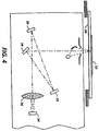
- Figure 4 is a schematic diagram showing certain constructional details of a document scanner of the printing system shown in Figure 1;
- Figures 5A, 5B and 5C comprise a schematic block diagram showing the major parts of the control section for the printing system shown in Figure 1;
- Figure 6 is a block diagram of an operating system, together with printed wiring boards and shared line connections for the printing system shown in Figure 1; and
- Figure 7 is a view depicting an exemplary job programming ticket and job scorecard displayed on the User Interface (UI) touchscreen of the printing system shown in Figure 1.
- This invention relates to a method whereby a reproduction system obtains information from an image on a document entered into the system, by means of a taggant contained in the marking materials forming that image. A scanner is preferably used to obtain taggant information. The scanner may be, but need not be, a separate component connected to any image processor. For example,the invention maybe used with a scanner connected to a light lens xerographic system. However this is a relatively inflexible system. Preferably, a scanner is incorporated into an electronic reprographic system as described above. This permits the image signals to be manipulated in numerous ways with a great degree of flexibility.
- Marking materials may include visible materials such as toner, ink or marking film. They may also (or alternatively) include materials which are visible only in the ultraviolet or infrared portions of the light spectrum. Marking materials containing taggants may be applied to a substrate by any known means, preferably by a mechanical or electromechanical printing process such as lithography, xerography, ionography, electronic reprography, thermal transfer printing (for example by being incorporated in a thermal transfer film), ink jet printing, encapsulated marking material printing, or impact printing (for example through being incorporated into an impact printer ribbon such as a dot matrix or typewriter ribbon).
- Toners generally are particulate compositions comprising a resin medium and a coloring agent and, as required, a charge controlling agent and other additives, with a specific particle diameter range. Generally, toners are either pressure-fixable or heat fixable.
- A toner is used in the development of images on a copy document by a development station, for example a magnetic brush development station. The toner particles are agitated in the development station to exhibit a triboelectric charge of opposite polarity to a latent image charge pattern. The charged toner particles are selectively attracted to the oppositely charged latent image pattern. This toner-coated pattern is then transferred electrostatically or directly and converted by pressure and/or heat into an image on the copy substrate such as paper, transparency film or the like.
- Toners suitable for use in electrophotographic copiers and printers may have a wide variety of colors, such as black, red, magenta, green, blue, cyan, brown, yellow, purple, silver and gold. When it is desired to highlight certain features of a document, two or more colored toners may be used. Partial or full color images can also be produced by developing images with a plurality of toners such as cyan, magenta and yellow, or red, blue and green, and black toners.
- Generally, it is advantageous for such toners to exhibit low melting temperatures to enable low energy fusing of image patterns on substrates at low temperatures. It is also often advantageous for such toners to possess mean particle diameters of less than about 20, preferably less than about 10, microns to enable images of high resolution, low image noise and high color fidelity. Further, it is generally desirable for these small diameter toners to have very narrow size distributions, preferably in the range of a geometric size dispersity (GSD) of 1.0 to 1.5, more preferably 1.2 to 1.3, to avoid difficulties in electrophotographic development and transfer associated with oversize toner particles and extremely fine toner particles.
- Inks generally used in an ink-jet printing system preferably comprise inks which are capable of being utilized without clogging or leaking in either the type of printing system which uses thermal energy to produce a vapor bubble in an ink-filled channel to expel a drop of ink, or the type of system which uses a piezoelectric transducer to produce a pressure pulse that expels droplets from a nozzle. Known ink jet inks generally comprise a dye which is soluble in an ink vehicle such as water or a mixture comprising water and a water soluble or water miscible organic solvent. Suitable water miscible organic solvents include ethylene glycol, propylene glycol, diethylene glycols, glycerine, dipropylene glycols, polyethylene glycols, polypropylene glycols, glycerine, dipropylene glycols, polyethylene glycols, polypropylene glycols, amides, ethers, carboxylic acids, esters, alcohols, organosulfides, organosulfoxides, sulfones, dimethylsulfoxide, sulfolane, alcohol derivatives, carbitol, butyl carbitol, cellusolve, ether derivatives, amino alcohols, ketones, and other water miscible materials, as well as mixtures thereof. When mixtures of water and water miscible organic liquids are selected as the liquid vehicle, the water to organic ratio may be in any effective range, and typically is from about 100:0 to about 30:70, preferably from about 97:3 to about 50:50. The non-water component of the liquid vehicle generally serves as a humectant which has a boiling point higher than that of water (100°C). Heterophase ink jet inks are also known.
- Inks generally contain a dye. Generally, any effective dye, such as one of the direct dyes or the acid dyes, can be selected as the colorant, provided that it is compatible with the other ink components and is soluble in the liquid vehicle. Examples of suitable dyes include anthraquinones, monoazo dyes, disazo dyes, phthalocyanines, aza(18)annulenes, and formazan copper complexes.
- Polymeric additives can also be added to inks to enhance their viscosity. Such additives include water soluble polymers such as gum arabic, polyacrylate salts, polymethacrylate salts, polyvinyl alcohols, hydroxy propylcellulose, hydroxyethylcellulose, polyvinyl- pyrrolidinone, polyvinylether, starch, polysaccharides, and the like. Polymeric additives may be present in inks in amounts of from 0 to about 5 percent by weight, and preferably from about 0.01 to about 2.5 percent by weight.
- Other optional additives to inks include biocides such as
Dowicil 150, 200, and 75, benzoate salts, sorbate salts, and the like, present in an amount of from about 0.0001 to about 4 percent by weight, and preferably from about 0.01 to about 2.0 percent by weight; humectants and penetration control additives such as ethylene glycol, diethyleneglycol, N-methylpyrolidinone, propylene glycol, hydroxyethers, ethers, amides, sulfoxides, ketones, lactones, esters, alcohols, butyl carbitol, benzyl alcohol, cyclohexylpyrrolidinone, 1,2-hexanediol, and the like, present in an amount of from 0 to about 50 percent by weight, and preferably from about 5 to about 40 percent by weight; pH controlling agents such as acids or bases, phosphate salts, carboxylate salts, sulfite salts, amine salts and the like, present in an amount of from 0 to about 1 percent by weight and preferably from about 0.01 to about 1 percent by weight, or the like. - Inks can be prepared by any process suitable for preparing aqueous-based inks. For example, the ink ingredients can be mixed in the desired amounts and stirred until a uniform ink composition results (typically about 30 minutes, although the mixing/stirring time can be either greater or less than this period). While not required, the ink ingredients can be heated during mixing if desired. Subsequent to mixing and stirring, the ink composition generally is filtered to remove any solid or particulate matter. Any other suitable processes for preparing inks can also be employed.
- Thermal transfer ribbons and impact printer ribbons are typically comprised of a substrate, usually a polyester film such as Mylar® coated with one or more layers of waxy components which contain pigments or dyes as colorants. The waxes may include many different types, blended so as to ensure melting under controlled conditions in thermal transfer devices and release from the substrate under pressure in impact printing devices. The properties are also adjusted through various wax components to ensure that images adhere to the marking substrates such as paper or transparencies and do not smear. Waxes include but are not restricted to families of carnauba waxes, beeswax and the like. The pigments can be any of those used in toners or inks, as can the taggant materials.
- According to embodiments of the present invention, taggant materials are provided in the basic marking material (toner, ink or marking film) for subsequent identification by the printing system. A "taggant" is defined herein as an additive to the marking material which can be combined with a marking material composition, and is selectively detectable independently from the primary colorant (e.g., pigment or dye) of the marking material. Preferred taggants will respond to an external stimulus in a way that can be specifically recognized by a reproduction system. For example, a taggant may emit light (e.g., fluoresce) at a certain wavelength band, preferably a narrow band in a near ultraviolet or near infrared portion of the light spectrum, upon exposure to white, ultraviolet or infrared light. The system can recognize this emitted light and, through information programmed into its memory, identify the specific marking material associated with the taggant which emits light at that wavelength. The system can also access significant information in its memory relating to that marking material to perform various functions.
- A taggant may be composed of a material which fluoresces or reflects light of visible or, preferably, "invisible" wavelengths. However, it should not interfere with the color of the marking material in which it is utilized within the image. For example, in a visible ink, the taggant would preferably fluoresce or reflect in an invisible (IR or UV) wavelength; for an "invisible" ink which reflects UV light, the taggant would preferably reflect or fluoresce in a separate part of the UV spectrum or in the IR spectrum. In a less preferred embodiment, the taggant would fluoresce or reflect light in a very narrow wavelength band within the same portion of the spectrum more broadly emitted or reflected by a colorant in the marking material. This would create a "peak" on the spectral response of the colorant which would be recognizable by a scanner, but which would not substantially interfere with perception of the image.
- Taggants can be blended into toner, ink or marking film materials as an additive or can be chemically or physically bonded to one of the constituent materials in the toner or ink. It is possible to have a taggant attached chemically to a number of pigment or dye materials such that the marking material in which the taggant is incorporated may be identified by the system upon appropriate illumination by a scanner.
- Generally any fluorescent dye may be selected as a taggant in inks or toners of the present invention. Exemplary taggant dyes for inks include, for example, 4,4'-bis(triazin-2-ylamino)stilbene-2,2'-disulfonic acids, 2-(stilben-4-yl)naphthotriazoles, 2-(4-phenylstilben-4-yl) benzoxazoles, 4,4-bis(triazo-2yl) stilbene-2,2'-disulfonic acids, 1,4-bis(styryl)biphenyls, 1,3-diphenyl-2- pyrazolines, bis(benzazol-2-yl) derivatives, 3-phenyl-7- (triazin-2-yl)coumarins, carbostyrils, naphthalimides, 3,7-diaminodibenzothiophen-2,8-disulfonic acid-5,5-dioxide and the like.
- Similarly, examples of fluorescent dyes suitable for use in particulate toners include stilbene derivatives such as 2-(4-phenylstilben-4-yl) benzoxazoles, 4,4'- bis(triazin-2-ylamino)-2,2' disulfonic acids and the like; pyrazoline derivatives such as 1,3-diphenyl-2-pyrazoline and its derivatives; biphenyls such as 4,4-bis(styryl)- biphenyl and its derivatives; coumarins such as 4-methyl- 7-aminocoumarin and 3-phenyl-7-(trazin-2-ylamino)coumarin; carbostyrils such as 3-phenyl-7-nitrocarbostyril; dibenzothiophene-5,5-dioxides such as 3,7-diaminobenzo- thiophene-2,8-disulfonic acid-5,5-dioxide; pyrene derivatives; pyridotriazoles; and the like. Fluorescent pigments (e.g., fluorescent dye(s) incorporated in resin particles) are also particularly suitable as taggants.
- When a taggant fluoresces or reflects light at a predetermined wavelength, the output light for each taggant can be detected and the presence or absence of taggant can be determined by equipment well known in the art. This information can then be processed further to perform, for example, the special functions of the printing system described herein. The necessary algorithms can readily be prepared by those of ordinary skill in the art without undue experimentation. They will generally include comparing the detected taggant wavelength to a "table" containing a plurality of taggant wavelengths and associated information maintained in the system memory. The "associated information" may include the identity of toners, inks or marking films containing the detected taggant(s) and the spectral response of colorants in those toners or inks; various types of instructional information for the reproduction system; or the like. The information accessed through use of the table permits precisely tailored control of the image reproduction. Many printing systems are capable of performing various specialized functions between the scanning and printing function such as color enhancement, correction and translation, document "dry-cleaning", and a number of security applications. These functions may be either enabled or controlled by the information made available by the present invention.
- Where an original document is in color, the taggant may provide information related to the nature and color of the marking material in which the taggant is incorporated. For example, in a color reproduction process employing magenta, cyan and yellow toners, each toner may be provided with a taggant material specific to the particular toner or colorant therein. Upon production of a color document containing one or more of such taggant-containing toners, the one or more taggants remain in the developed document. Subsequently, these taggant materials can be recognized with appropriate apparatus.
- Color correction, color enhancement, and color translation are important functions facilitated by the present invention. In reproducing color originals, three values (e.g., red, green, blue) are normally generated by a color scanner, and can then be used to calculate colorimetric data through any of a variety of techniques well known in the art. For colorimetrically accurate reproduction, the reproduction system must obtain accurate spectral response values (i.e., spectrophotometric curve) from the original, and replicate those values with colorimetric precision in the marking material it uses to generate the copy. Existing color copying systems can adequately replicate the spectral response values which reach their image processing equipment because they are designed to use specific marking materials with known spectral responses. These known marking materials may be combined in a known manner to achieve specified colors.
- However, the spectral response values which reach the image processing equipment of existing reproduction systems are often inaccurate, because the marking materials of the original are generally unknown and variable. For example, a green colorant of one type may not be exactly the same color as a green colorant of another type. A conventional reproduction system will obtain an averaged value when it scans an image containing such a colorant, or an image containing a combination of colorants, and will use that averaged value as the basis for application of marking materials on the copy. This often results in the copy having a different color appearance from the original.
- According to an embodiment of the present invention, however, a reproduction system will be able to identify the particular material forming the image being scanned by recognition of one or more taggants therein. From information preprogrammed into its memory, the system will be able to adjust the scanned color values to accurate colorimetric values using spectral response data for the specific marking materials identified, using algorithms which can readily be generated by those of ordinary skill in the art without undue experimentation upon reading the present specification. It can then create a reproduced image on a display device or via a printing system based on the actual spectral response values of the original image in a known manner. Thus the embodiment can provide for color correction in a simple manner based upon the incorporation of separate identifiable taggants in various marking materials. For example, a system scanning an ink jet original, having detailed information derived from the taggants in that ink and corresponding information in its memory as to the colorimetric properties of that ink, can readily create an accurate copy using toner particles which generally include different pigments or using the phosphors of a CRT display device.
- To perform this color correction for any particular image, it is only necessary to know with what pigments or dyes the image was made. Only a low resolution scanner (sensor) is necessary to pick up the taggant wavelength needed to generate this additional information, as distinct from the high resolution scanner normally used to detect image information. This scanner may respond to a broad wavelength light source using very selective wavelength filters to select the taggant signals, or it may be tuned to specific wavelengths as from a laser light source.
- Variants of color correction are also enabled by the present invention. For example, rather than precisely duplicating the original image, a specific color component of the original image can effectively be enhanced in the copy without enhancing other colors in the original image as might occur in existing reproduction systems. Alternatively, the detailed information about the original colors provided by the taggants in the inventive system can permit simplified translation from one set of colors to another. For example, an image containing a set of colors could be translated to an image containing complementary colors (e.g., the negatives of the first image colors); or to an image containing a more restricted set of colors (e.g., from a full-color image to a subset of the colors, e.g., a two-color image comprising a different color and shades of gray to represent other original colors, or an image comprising different shades of a single color (e.g., a gray scale or "black-and-white" image)).
- A system according to one embodiment of the present invention may also be employed so that the text of a document and annotations on the document can be separately identified either as being a part of an original document or as being subsequently applied marks. If marks are subsequently applied to documents produced from marking materials containing taggants as described above, these marks can be separately identified and distinguished. Ink or pencil annotations can be distinguished from the taggant-containing toner, ink or marking film material in the original image. For example, an original image may be formed using a marking material containing a taggant. When marks are subsequently applied to the original, these marks can be distinguished from the original image. Upon reproduction, the original image can be reproduced with or without the subsequently applied marks. This can, for example, be used to make a clean copy from a document that has been annotated or, to the contrary, to make a copy in which annotations are highlighted or are even the only image copied. The scanner identifies the taggant material and distinguishes it from "untagged" material, and utilizes the information during reproduction.
- Taggants may also provide security for important documents. The system according to an embodiment of the present invention is capable of identifying documents (as well as marking materials) containing taggants which may be present in the toner or ink used to create an image on the document. Thus, copies made using such toner or ink doped with taggant can be readily identified. This can permit subsequent identification of the source of an image, generally by type of machine (e.g., for statistical data gathering) or more specifically by facility where a copy was made or even by the specific machine unit in which a copy was made (e.g., for document tracking).
- Documents or portions thereof may also be made incapable of being copied by using tagged marking materials for at least the portion of the document for which protection is desired. The identification of a predetermined taggant may signal the system to prevent scanning, storing or developing operations, of the whole document or areas where the particular taggant is present. Similarly, images made by machines which do not provide taggants can readily be distinguished from taggant containing images, thus facilitating document control.
- Referring now to the drawings, and particularly to Figures 1 and 2 thereof, there is shown an exemplary electronic
reprographic printing system 2 for processing print jobs in accordance with an embodiment of the present invention.Printing system 2, for purposes of explanation, is divided into ascanner section 6, controller section 7, andprinter section 8. While a specific printing system is shown and described, the present invention may be used with other types of printing systems such as ink jet marking systems, ionographic systems, xerographic systems, lithographic systems, thermal transfer systems or ribbon- oriented direct marking systems. - Referring particularly to Figures 2-4,
scanner section 6 incorporates atransparent platen 20 on which thedocument 22 to be scanned is located. At least onelinear array 24 is supported for reciprocating scanning movement belowplaten 20.Lens 26 and mirrors 28, 29, 30 cooperate to focusarray 24 on a line-like segment ofplaten 20 and the document being scanned thereon.Array 24 provides image signals or pixels representative of the image scanned which, after suitable processing byprocessor 25, are output to controller section 7.Scanner 6 may also include at least one separate scanner component of low resolution and comprising filters and/or light sources capable of detection in the UV and IR regions, or this function may be incorporated into the main scanner. The function of this additional scanner component is to process information about the presence or absence of color toners or inks and/or taggants in marking materials. - The taggant scanner component could include a broad wavelength illumination source with a narrow wavelength filter for each taggant to be detected. Alternatively, the taggant scanner component could include at least one narrow wavelength illumination source (such as a laser), and at least one specific wavelength sensor.
-
Processor 25 converts the analog image signals output byarray 24 to digital image signals, and processes the digital image signals as required to enablesystem 2 to store and handle the image data in the form required to carry out the job programmed.Processor 25 also provides enhancements and changes to the image signals such as filtering, thresholding, screening, cropping, reduction/enlarging,etc. -
Documents 22 to be scanned may be located onplaten 20 for scanning by automatic document handler (ADH) 35 operable in either a Recirculating Document Handling (RDH) mode or a Semi-Automatic Document Handling (SADH) mode. A manual mode including a Book mode and a Computer Forms Feeder (CFF) mode are also provided, the latter to accommodate documents in the form of computer fanfold. For RDH mode operation,document handler 35 has adocument tray 37 in which documents 22 are arranged in stacks or batches. Thedocuments 22 intray 37 are advanced byvacuum feed belt 40, document feed rolls 41 and document feed belt 42 ontoplaten 20 where the document is scanned. Following scanning, the document is removed fromplaten 20 by belt 42 and returned totray 37 by document feed rolls 44. - For operation in the SADH mode, a
document entry slot 46 provides access to the document feed belt 42 betweentray 37 andplaten 20 through which individual documents may be inserted manually for transport to platen 20. Feed rolls 49 behindslot 46 form a nip for engaging and feeding the document to feed belt 42 and ontoplaten 20. Following scanning, the document is removed fromplaten 20 and discharged intocatch tray 48. - For operation in the CFF mode, computer forms material is fed through
slot 46 and advanced by feed rolls 49 to document feed belt 42 which in turn advances a page of the fanfold material into position onplaten 20. - Referring to Figures 2 and 3,
printer section 8 may comprise a laser type printer and, for purposes of explanation, is separated into a Raster Output Scanner (ROS)section 87,print module section 95, paper supply section 107, andfinisher 120.ROS 87 has alaser 90, the beam of which is split into two imaging beams 94. Eachbeam 94 is modulated in accordance with the content of an image signal input by acousto-optic modulator 92 to provide dual imaging beams 94.Beams 94 are scanned across a movingphotoreceptor 98 ofPrint Module 95 by the mirrored facets of arotating polygon 100 to expose two image lines onphotoreceptor 98 with each scan and create the latent electrostatic images represented by the image signal input tomodulator 92.Photoreceptor 98 is uniformly charged by corotrons 102 at a charging station preparatory to exposure by imaging beams 94. The latent electrostatic images are developed by toner or developer at 104 and transferred attransfer station 106 to aprint media 108 delivered by media supply section 107.Media 108 may comprise any of a variety of materials (e.g., paper, transparency film or the like), sheet sizes, types, and colors. For transfer, the print media are brought forward in timed registration with the developed image onphotoreceptor 98 from either amain paper tray 110 or fromauxiliary paper trays print media 108 is permanently fixed or fused byfuser 116 and the resulting prints discharged either tooutput tray 118, or tofinisher 120. For color printers, the above process is repeated for each color, the color images being overlaid to form the final image.Finisher 120 includes astitcher 122 for stitching or stapling the prints together to form books and athermal binder 124 for adhesively binding the prints into books. - Referring to Figures 1, 2 and 5, controller section 7 is, for explanation purposes, divided into an
image input controller 50, User Interface (UI) 52,system controller 54,main memory 56,image manipulation section 58, andimage output controller 60. - Referring particularly to Figures 5A-5C, control section 7 includes a plurality of Printed Wiring Boards (PWB's) 70, PWB's 70 being coupled with one another and with
System Memory 61 by a pair ofmemory buses Memory controller 76couples System Memory 61 withbuses plural system processors 78; low speed I/O processor PWB 70-2 havingUI communication controller 80 for transmitting data to and fromUI 52; PWB's 70-3, 70-4 and 70-5 having disk drive controller/processors 82 for transmitting data to and from disks 90-1, 90-2 and 90-3, respectively, of main memory 56 (image compressor/processor 51 for compressing the image data on PWB 70-3); image manipulation PWB 70-6 with image manipulation processors ofimage manipulation section 58; image generation processor PWB's 70-7 and 70-8 withimage generation processor 86 for processing the image data for printing byprinter section 8; dispatch processor PWB 70-9 havingdispatch processors printer section 8; and boot control-arbitration-scheduler PWB 70-10. - The scanned image data input from
processor 25 ofscanner section 6 to controller section 7 is compressed by image compressor/processor 51 ofimage input controller 50 on PWB 70-3. As the image data passes through compressor/processor 51, it is segmented into slices N scanlines wide, each slice having a slice pointer. The compressed image data, together with slice pointers and any related image descriptors providing image specific information (such as height and width of the document in pixels, the compression method used, pointers to the compressed image data, and pointers to the image slice pointers), are placed in an image file. The image files, which represent different print jobs, are temporarily stored insystem memory 61 which comprises a Random Access Memory or RAM pending transfer tomain memory 56 where the data is held pending use. - As best seen in Figure 1,
User Interface 52 includes a combined operator controller/CRT display comprised of aninteractive touchscreen 62,keyboard 64, andmouse 66.Ul 52 interfaces the operator withprinting system 2, enabling the operator to program print jobs and other instructions, to obtain system operating information, instructions, programming information, diagnostic information, etc. Items displayed ontouchscreen 62 such as files and icons are actuated by either touching the displayed item onscreen 62 with a finger or by usingmouse 66 to point cursor 67 to the item selected and keying the mouse. -
Main memory 56 has plural hard disks 90-1,90-2,90-3 for storing machine operating system software, machine operating data, taggant information and tables, and the scanned image data currently being processed. - When the compressed image data in
main memory 56 requires further processing, or is required for display ontouchscreen 62 ofUI 52, or is required byprinter section 8, the data is accessed inmain memory 56. Where further processing other than that provided byprocessor 25 is required, the data is transferred to imagemanipulation section 58 on PWB 70-6 where the additional processing steps such as color image processing, color correction, enhancement and translation, security processing, highlighting, collation, make ready, decomposition, etc., are carried out. Following processing,the data may be returned tomain memory 56, sent toUI 52 for display ontouchscreen 62, or sent to imageoutput controller 60. - Image data output to image
output controller 60 is decompressed and readied for printing byimage generating processors 86 of PWB's 70-7, 70-8 (seen in Figure 5A). Following this, the data is output bydispatch processors printer section 8. Image data sent toprinter section 8 for printing is normally purged frommemory 56 to make room for new image data. - Referring particularly to Figure 6, system control signals are distributed via a plurality of printed wiring boards (PWB's). These include
EDN core PWB 130, MarkingImaging core PWB 132, PaperHandling core PWB 134, and FinisherBinder core PWB 136 together with various Input/Output (I/O) PWB's 138. Asystem bus 140 couples the core PWB's 130, 132, 134 and 136 with each other and with controller section 7 whilelocal buses 142 serve to couple the I/O PWB's 138 with each other and with their associated core PWB. - On machine power up, the Operating System software is loaded from
memory 56 toEDN core PWB 130 and from there to the remaining core PWB's 132, 134 and 136 viabus 140, eachcore PWB bus 140 and control data to and from I/O PWB's 138 vialocal buses 142. Additional ROM, RAM, and NVM memory types are resident at various locations withinsystem 2. - Referring to Figure 7, jobs are programmed in a Job Program mode in which there is displayed on touchscreen 62 a
Job Ticket 150 and aJob Scorecard 152 for the job being programmed.Job Ticket 150 displays various job selections programmed whileJob Scorecard 152 displays the basic instructions to the system for printing the job. - While the invention has been described with reference to particular preferred embodiments, the invention is not limited to the specific examples given, and other embodiments and modifications can be made by those skilled in the art without departing from the scope of the invention.
Claims (15)
- A process for controlling a reproduction system, characterised by scanning an image to detect at least one taggant in at least one marking material forming said image, comparing each detected taggant with at least one known taggant associated with at least one known type of marking material, and issuing instructions determined by results of said comparison to said reproduction system.
- A process for controlling a reproduction system, characterised by scanning an image to detect at least one taggant in at least one marking material forming said image; and issuing instructions to said reproduction system, wherein said instructions cause said reproduction system to take at least one action selected from the group consisting of:(a) prohibiting reproduction of those portions of said image formed by a said marking material containing at least one predetermined detected taggant, and reproducing of all other portions of said image;(b) prohibiting reproduction of any part of said image upon detection of at least one predetermined taggant;(c) reproducing only those portions of said image formed by a said marking material containing at least one predetermined taggant;(d) reproducing portions of said image formed by a said marking material containing at least one predetermined taggant in a different manner from that in which said system reproduces portions of said image formed by a said marking material not containing said at least one predetermined taggant; and(e) identifying a source of said image on the basis of detection of at least one predetermined taggant.
- A process as claimed in claim 1 or claim 2, characterised in that between said scanning step and said issuing step, is a step of comparing each detected taggant to a table in which at least two taggants are each respectively associated with different instructional information.
- A process as claimed in claim 3, characterised in that said different instructional information includes at least two different known types of marking materials, said known types of marking materials in said table each contain a different colorant; and said instructions cause a print color adjustment in said reproduction system based on identification of a said colorant corresponding to a detected taggant.
- A process as claimed in any one of claims 1 to 4, characterised by means for outputting an image corresponding to said scanned image, said image being scanned to detect at least two taggants in at least two different colored marking materials forming said scanned image, said instructions causing a print color adjustment comprising correction of color of said outputted image to be substantially identical to the color of said scanned image, and/or comprising enhancement of at least one color of said scanned image in said outputted image, and/or comprising translation from a first set of colors in said scanned image to a second set of colors in said outputted image.
- A process as claimed in any one of claims 1 to 5, characterised in that said marking material contains a colorant which reflects or emits light in one portion of the light spectrum, and said taggant reflects or emits light in a distinguishable portion of the light spectrum.
- A reproduction system including a scanner section (6) and a controller section (7), characterised in that said scanner section (6) comprises means for scanning an image to detect image signals and taggant signals from at least one marking material forming said image and for sending scanner output signals to said controller section (7), and said controller section (7) comprises means for processing said scanner output signals to generate instruction signals for said reproduction system, wherein said instruction signals cause said reproduction system totake at least one action selected from the group consisting of:(a) prohibiting reproduction of those portions of said image formed by a said marking material containing at least one predetermined detected taggant, and reproducing all other portions of said image;(b) prohibiting reproduction of any part of said image upon detection of at least one predetermined taggant;(c) reproducing only those portions of said image formed by a said marking material containing at least one predetermined taggant;(d) reproducing portions of said image formed by a said marking material containing at least one predetermined taggant in a different manner from that in which said system reproduces portions of said image formed by a said marking material not containing said at least one predetermined taggant; and(e) identifying a source of said image on the basis of detection of at least one predetermined taggant.
- A reproduction system as claimed in claim 7, characterised by means for implementing any one of the processes as claimed in claims 1 to 6.
- A method of producing an image, characterised by applying at least one marking material containing a taggant to a substrate by a mechanical or electromechanical printing process.
- A method as claimed in claim 9, characterised in that said printing process is selected from the group consisting of lithography, xerography, ionography, electronic reprography, impact printing, ink jet printing and thermal transfer printing.
- A method as claimed in claim 9 or claim 10, characterised in that said marking material is selected from the group consisting of toner, ink jet ink, encapsulated marking material and marking film.
- A marking material, characterised in that said marking material comprises a taggant and a colorant, said marking material being specially adapted for use in a mechanical or electromechanical printing process.
- A marking material as claimed in claim 12, characterised in that said marking material is selected from the group comprising a toner, an encapsulated marking material, and an ink jet ink.
- A marking material as claimed in claim 12, characterised in that said marking material is incorporated in an impact printer ribbon or thermal transfer film.
- A marking material as claimed in claim 12, characterised in that said taggant is a fluorescent pigment or dye.
Applications Claiming Priority (2)
| Application Number | Priority Date | Filing Date | Title |
|---|---|---|---|
| US636264 | 1990-12-31 | ||
| US07/636,264 US5225900A (en) | 1990-12-31 | 1990-12-31 | Method of storing information within a reproduction system |
Publications (3)
| Publication Number | Publication Date |
|---|---|
| EP0493961A2 true EP0493961A2 (en) | 1992-07-08 |
| EP0493961A3 EP0493961A3 (en) | 1993-08-18 |
| EP0493961B1 EP0493961B1 (en) | 1997-03-05 |
Family
ID=24551156
Family Applications (1)
| Application Number | Title | Priority Date | Filing Date |
|---|---|---|---|
| EP91311981A Expired - Lifetime EP0493961B1 (en) | 1990-12-31 | 1991-12-23 | Method of storing information |
Country Status (4)
| Country | Link |
|---|---|
| US (2) | US5225900A (en) |
| EP (1) | EP0493961B1 (en) |
| JP (1) | JP3244185B2 (en) |
| DE (1) | DE69124973T2 (en) |
Cited By (9)
| Publication number | Priority date | Publication date | Assignee | Title |
|---|---|---|---|---|
| EP0595583A1 (en) * | 1992-10-26 | 1994-05-04 | Canon Kabushiki Kaisha | Non-visualized information recording medium and apparatus for detecting the same |
| EP0599218A1 (en) * | 1992-11-20 | 1994-06-01 | Toppan Printing Co., Ltd. | Method and copying machine for preventing illegal copying |
| EP0605259A2 (en) * | 1993-01-01 | 1994-07-06 | Canon Kabushiki Kaisha | Image reading apparatus and image processing apparatus |
| GB2276510A (en) * | 1993-03-23 | 1994-09-28 | Ricoh Kk | Copying system having selectable units |
| EP0629926A2 (en) * | 1993-06-15 | 1994-12-21 | Sharp Kabushiki Kaisha | Image reading apparatus and image processor incorporating the same |
| WO1996031049A1 (en) * | 1995-03-29 | 1996-10-03 | Paul Lahmi | Secure method for duplicating sensitive documents |
| GB2281392B (en) * | 1993-01-28 | 1996-11-06 | Ricoh Kk | Specific document discriminating apparatus and image reading apparatus using it therein |
| DE4447705C2 (en) * | 1993-10-30 | 2000-04-13 | Ricoh Kk | Image processing to prevent copying of projected document |
| EP1099199A1 (en) * | 1998-07-17 | 2001-05-16 | Imaging Automation, Inc. | Secure document reader and method therefor |
Families Citing this family (115)
| Publication number | Priority date | Publication date | Assignee | Title |
|---|---|---|---|---|
| US6766953B1 (en) | 1992-05-01 | 2004-07-27 | Hewlett-Packard Development Company, L.P. | Tape indicia on clear film media |
| US5543177A (en) * | 1992-11-05 | 1996-08-06 | Xerox Corporation | Marking materials containing retroreflecting fillers |
| JPH06210987A (en) * | 1993-01-19 | 1994-08-02 | Canon Inc | Recording medium of information made invisible, detecting device of information made invisible and recording agent |
| JP2882511B2 (en) * | 1993-03-12 | 1999-04-12 | ノーリツ鋼機株式会社 | Image printer |
| JPH0756956A (en) * | 1993-07-22 | 1995-03-03 | Xerox Corp | Method for access of data based on image created by human being |
| JPH0778251A (en) * | 1993-07-22 | 1995-03-20 | Xerox Corp | Verifying method of source |
| US5510877A (en) * | 1994-04-20 | 1996-04-23 | Xerox Corporation | Method and apparatus for lateral registration control in color printing |
| US5489763A (en) * | 1994-06-24 | 1996-02-06 | Xerox Corporation | Printing and encoding of documents having a magnetic strip |
| US5935755A (en) * | 1995-08-21 | 1999-08-10 | Xerox Corporation | Method for document marking and recognition |
| US7728845B2 (en) | 1996-02-26 | 2010-06-01 | Rah Color Technologies Llc | Color calibration of color image rendering devices |
| US5862217A (en) * | 1996-03-28 | 1999-01-19 | Fotonation, Inc. | Method and apparatus for in-camera encryption |
| DE69737883T2 (en) | 1996-04-25 | 2008-03-06 | Bioarray Solutions Ltd. | LIGHT-REGULATED, ELECTROKINETIC COMPOSITION OF PARTICLES TO SURFACES |
| AU748939B2 (en) * | 1997-02-20 | 2002-06-13 | Regents Of The University Of California, The | Plasmon resonant particles, methods and apparatus |
| US5983065A (en) * | 1997-07-23 | 1999-11-09 | Xerox Corporation | Method of printing secure documents |
| WO1999010866A1 (en) * | 1997-08-25 | 1999-03-04 | Imagicolor Corp | A system for distributing and controlling color reproduction at multiple sites |
| US6636332B1 (en) | 1998-02-05 | 2003-10-21 | Eastman Kodak Company | System for reproducing images and method thereof |
| FR2780783B1 (en) * | 1998-07-06 | 2001-01-19 | Christian Stapfer | DEVICE FOR COLOR CODING OF DIGITAL IMAGES OF FLUORESCENT OBJECTS |
| US6644764B2 (en) | 1998-10-28 | 2003-11-11 | Hewlett-Packard Development Company, L.P. | Integrated printing/scanning system using invisible ink for document tracking |
| US6149719A (en) * | 1998-10-28 | 2000-11-21 | Hewlett-Packard Company | Light sensitive invisible ink compositions and methods for using the same |
| US6304345B1 (en) | 1998-12-14 | 2001-10-16 | Eastman Kodak Company | Auto resoration of a print |
| US6396599B1 (en) * | 1998-12-21 | 2002-05-28 | Eastman Kodak Company | Method and apparatus for modifying a portion of an image in accordance with colorimetric parameters |
| US6541100B1 (en) | 1998-12-31 | 2003-04-01 | Eastman Kodak Company | Imaged medium comprising sensor-readable indicia |
| US6169185B1 (en) | 1999-02-25 | 2001-01-02 | Day-Glo Color Corp. | Ink jet printing inks |
| US6795209B1 (en) * | 1999-10-14 | 2004-09-21 | Eastman Kodak Company | Method and apparatus for modifying a hard copy image digitally in accordance with instructions provided by consumer |
| AU3438801A (en) * | 1999-11-09 | 2001-05-30 | Spectra Science Corporation | Authentication and coding by size, shape, and fluorescence |
| US6969549B1 (en) | 1999-11-19 | 2005-11-29 | Hewlett-Packard Development Company, L.P. | Techniques to prevent leakage of fluorescing signals through print media or indicia tape |
| US6993655B1 (en) * | 1999-12-20 | 2006-01-31 | Xerox Corporation | Record and related method for storing encoded information using overt code characteristics to identify covert code characteristics |
| US6386671B1 (en) | 1999-12-29 | 2002-05-14 | Hewlett-Packard Company | Orientation independent indicia for print media |
| US7102648B1 (en) | 2000-04-11 | 2006-09-05 | Rah Color Technologies Llc | Methods and apparatus for calibrating a color display |
| US6610351B2 (en) | 2000-04-12 | 2003-08-26 | Quantag Systems, Inc. | Raman-active taggants and their recognition |
| JP4744778B2 (en) | 2000-06-21 | 2011-08-10 | バイオアレイ ソルーションズ リミテッド | Method for analyzing multiple analyte molecules using a specific random particle array |
| US9709559B2 (en) | 2000-06-21 | 2017-07-18 | Bioarray Solutions, Ltd. | Multianalyte molecular analysis using application-specific random particle arrays |
| EP1311396A4 (en) * | 2000-08-14 | 2005-06-08 | Silverbrook Res Pty Ltd | Interface surface printer using invisible ink |
| US6477227B1 (en) | 2000-11-20 | 2002-11-05 | Keymaster Technologies, Inc. | Methods for identification and verification |
| US20020063879A1 (en) * | 2000-11-29 | 2002-05-30 | Eastman Kodak Company | Method and apparatus for reproducing an image with embedded cutting instructions and product thereof |
| US6501825B2 (en) | 2001-01-19 | 2002-12-31 | Keymaster Technologies, Inc. | Methods for identification and verification |
| US7262063B2 (en) | 2001-06-21 | 2007-08-28 | Bio Array Solutions, Ltd. | Directed assembly of functional heterostructures |
| JP4377689B2 (en) | 2001-10-15 | 2009-12-02 | バイオアレイ ソリューションズ リミテッド | Combined analysis of polymorphic loci with simultaneous interrogation and enzyme-mediated detection |
| US6963973B2 (en) | 2001-10-17 | 2005-11-08 | Hewlett-Packard Development Company, L.P. | Chain of custody system and method |
| US7747655B2 (en) | 2001-11-19 | 2010-06-29 | Ricoh Co. Ltd. | Printable representations for time-based media |
| US7861169B2 (en) | 2001-11-19 | 2010-12-28 | Ricoh Co. Ltd. | Multimedia print driver dialog interfaces |
| US6909770B2 (en) * | 2001-12-05 | 2005-06-21 | The United States Of America As Represented By The United States National Aeronautics And Space Administration | Methods for identification and verification using vacuum XRF system |
| US20040022355A1 (en) * | 2001-12-05 | 2004-02-05 | Bruce Kaiser | Methods for identification and verification of materials containing elemental constituents |
| US6850592B2 (en) * | 2002-04-12 | 2005-02-01 | Keymaster Technologies, Inc. | Methods for identification and verification using digital equivalent data system |
| US20030194052A1 (en) * | 2002-04-12 | 2003-10-16 | Price L. Stephen | Methods for identification and verification |
| US7120272B2 (en) * | 2002-05-13 | 2006-10-10 | Eastman Kodak Company | Media detecting method and system for an imaging apparatus |
| US6673500B1 (en) | 2002-08-20 | 2004-01-06 | Xerox Corporation | Document security processes |
| US6664017B1 (en) | 2002-08-20 | 2003-12-16 | Xerox Corporation | Document security processes |
| US7052730B2 (en) * | 2002-08-20 | 2006-05-30 | Xerox Corporation | Document security processes |
| AU2003298655A1 (en) | 2002-11-15 | 2004-06-15 | Bioarray Solutions, Ltd. | Analysis, secure access to, and transmission of array images |
| SE0203853D0 (en) | 2002-12-23 | 2002-12-23 | Anoto Ab | Data code |
| US7255895B2 (en) * | 2003-01-21 | 2007-08-14 | Bioarray Solutions, Ltd. | Method for controlling solute loading of polymer microparticles |
| US20040172537A1 (en) * | 2003-02-28 | 2004-09-02 | Baus George Harold | System and method for tracking and authenticating items through an internet web site |
| US20040187564A1 (en) * | 2003-03-28 | 2004-09-30 | Hagerty Jon C. | Dateable inks |
| US7703002B2 (en) * | 2003-03-31 | 2010-04-20 | Ricoh Company, Ltd. | Method and apparatus for composing multimedia documents |
| US7536638B2 (en) * | 2003-03-31 | 2009-05-19 | Ricoh Co., Ltd. | Action stickers for identifying and processing stored documents |
| US7552381B2 (en) * | 2003-03-31 | 2009-06-23 | Ricoh Co., Ltd. | Check boxes for identifying and processing stored documents |
| US7757162B2 (en) | 2003-03-31 | 2010-07-13 | Ricoh Co. Ltd. | Document collection manipulation |
| US7509569B2 (en) * | 2003-03-31 | 2009-03-24 | Ricoh Co., Ltd. | Action stickers for nested collections |
| US20070050696A1 (en) * | 2003-03-31 | 2007-03-01 | Piersol Kurt W | Physical key for accessing a securely stored digital document |
| US7739583B2 (en) * | 2003-03-31 | 2010-06-15 | Ricoh Company, Ltd. | Multimedia document sharing method and apparatus |
| WO2004089056A2 (en) * | 2003-04-01 | 2004-10-21 | Keymaster Technologies, Inc. | Exempt source for an x-ray fluorescence device |
| WO2004089640A2 (en) | 2003-04-04 | 2004-10-21 | Angstrom Technologies, Inc. | Methods and ink compositions for invisibly printed security images having multiple authentication features |
| US6860930B2 (en) | 2003-06-25 | 2005-03-01 | Xerox Corporation | Phase change inks containing branched triamides |
| US7275159B2 (en) | 2003-08-11 | 2007-09-25 | Ricoh Company, Ltd. | Multimedia output device having embedded encryption functionality |
| WO2005029705A2 (en) | 2003-09-18 | 2005-03-31 | Bioarray Solutions, Ltd. | Number coding for identification of subtypes of coded types of solid phase carriers |
| NZ546072A (en) | 2003-09-22 | 2009-08-28 | Bioarray Solutions Ltd | Surface immobilized polyelectrolyte with multiple functional groups capable of covalently bonding to biomolecules |
| US20050060919A1 (en) * | 2003-09-23 | 2005-03-24 | Sun Yu | Greeting card incorporating ultraviolet light emitting diode |
| WO2005042763A2 (en) | 2003-10-28 | 2005-05-12 | Bioarray Solutions Ltd. | Optimization of gene expression analysis using immobilized capture probes |
| EP1694859B1 (en) | 2003-10-29 | 2015-01-07 | Bioarray Solutions Ltd | Multiplexed nucleic acid analysis by fragmentation of double-stranded dna |
| JP4127537B2 (en) * | 2004-02-04 | 2008-07-30 | 富士フイルム株式会社 | Image processing method, apparatus, and program |
| US7687271B2 (en) * | 2004-04-22 | 2010-03-30 | Kodak Graphic Communications Canada Company | Covert authentication method and apparatus |
| US20050280835A1 (en) * | 2004-06-17 | 2005-12-22 | Debusschere Eric T | Mouse support for a printing device |
| SE0401647D0 (en) * | 2004-06-28 | 2004-06-28 | Anoto Ab | Coding and decoding of data |
| US7428076B2 (en) * | 2004-08-02 | 2008-09-23 | Seiko Epson Corporation | Smart copying for variable cost, editable printouts |
| US7848889B2 (en) | 2004-08-02 | 2010-12-07 | Bioarray Solutions, Ltd. | Automated analysis of multiplexed probe-target interaction patterns: pattern matching and allele identification |
| US20060086901A1 (en) * | 2004-10-22 | 2006-04-27 | Price L S | Methods and apparatus for improving the reliability and accuracy of identifying, analyzing and authenticating objects, including chemicals, using multiple spectroscopic techniques |
| US7202883B2 (en) * | 2004-12-10 | 2007-04-10 | Xerox Corporation | Heterogeneous reactive ink composition |
| US7172276B2 (en) * | 2004-12-10 | 2007-02-06 | Xerox Corporation | Heterogeneous low energy gel ink composition |
| US7506813B2 (en) * | 2005-01-06 | 2009-03-24 | Quad/Graphics, Inc. | Resonator use in the print field |
| US20060257495A1 (en) * | 2005-05-11 | 2006-11-16 | Xerox Corporation | Method of purification of polyalkylene materials |
| US8486629B2 (en) | 2005-06-01 | 2013-07-16 | Bioarray Solutions, Ltd. | Creation of functionalized microparticle libraries by oligonucleotide ligation or elongation |
| JP4982486B2 (en) * | 2005-06-17 | 2012-07-25 | アノト アクティエボラーク | Method and system for combining position and information signs |
| US20070054130A1 (en) * | 2005-08-31 | 2007-03-08 | Illinois Tool Works, Inc. | Security laser printing film |
| US7572325B2 (en) * | 2005-11-30 | 2009-08-11 | Xerox Corporation | Ink carriers, phase change inks including same and methods for making same |
| US7758268B2 (en) * | 2005-12-20 | 2010-07-20 | Xerox Corporation | Hand held photochromic marking implement |
| US7829162B2 (en) * | 2006-08-29 | 2010-11-09 | international imagining materials, inc | Thermal transfer ribbon |
| US7786209B2 (en) * | 2006-10-27 | 2010-08-31 | Xerox Corporation | Nanostructured particles, phase change inks including same and methods for making same |
| EP3159742A1 (en) | 2007-08-21 | 2017-04-26 | Angstrom Technologies, Inc. | Stable emissive toner composition system and method |
| US20090097898A1 (en) * | 2007-10-16 | 2009-04-16 | Xerox Corporation | Hand held photochromic marking implement |
| US8186272B2 (en) * | 2007-12-28 | 2012-05-29 | Pitney Bowes Inc. | Method and system for drying ink on a substrate material |
| WO2010039139A1 (en) * | 2008-10-02 | 2010-04-08 | Hewlett-Packard Development Company, L.P. | Secure document creation with a multi-function apparatus |
| US20110279866A1 (en) * | 2009-01-23 | 2011-11-17 | Matheson Paul F | Method of processing a print job |
| US8968452B2 (en) | 2011-04-27 | 2015-03-03 | Xerox Corporation | Phase change inks containing crystalline trans-cinnamic diesters and amorphous isosorbide oligomers |
| EP2505356A1 (en) * | 2011-03-30 | 2012-10-03 | KBA-NotaSys SA | Device for offline inspection and color measurement of printed sheets |
| US9057712B1 (en) | 2011-10-27 | 2015-06-16 | Copilot Ventures Fund Iii Llc | Methods of delivery of encapsulated perfluorocarbon taggants |
| US9334335B2 (en) | 2012-11-30 | 2016-05-10 | Xerox Corporation | Surface layer |
| US9022546B1 (en) | 2013-11-25 | 2015-05-05 | Xerox Corporation | Method of jetting ink |
| US9683130B2 (en) | 2014-03-19 | 2017-06-20 | Xerox Corporation | Polydiphenylsiloxane coating formulation and method for forming a coating |
| US9494884B2 (en) | 2014-03-28 | 2016-11-15 | Xerox Corporation | Imaging plate coating composite composed of fluoroelastomer and aminosilane crosslinkers |
| US9428663B2 (en) | 2014-05-28 | 2016-08-30 | Xerox Corporation | Indirect printing apparatus employing sacrificial coating on intermediate transfer member |
| US9593255B2 (en) | 2014-09-23 | 2017-03-14 | Xerox Corporation | Sacrificial coating for intermediate transfer member of an indirect printing apparatus |
| US9611404B2 (en) | 2014-09-23 | 2017-04-04 | Xerox Corporation | Method of making sacrificial coating for an intermediate transfer member of indirect printing apparatus |
| US9550908B2 (en) | 2014-09-23 | 2017-01-24 | Xerox Corporation | Sacrificial coating for intermediate transfer member of an indirect printing apparatus |
| US9421758B2 (en) | 2014-09-30 | 2016-08-23 | Xerox Corporation | Compositions and use of compositions in printing processes |
| US9956760B2 (en) | 2014-12-19 | 2018-05-01 | Xerox Corporation | Multilayer imaging blanket coating |
| US9458341B2 (en) | 2015-02-12 | 2016-10-04 | Xerox Corporation | Sacrificial coating compositions comprising polyvinyl alcohol and waxy starch |
| US9816000B2 (en) | 2015-03-23 | 2017-11-14 | Xerox Corporation | Sacrificial coating and indirect printing apparatus employing sacrificial coating on intermediate transfer member |
| US9718964B2 (en) | 2015-08-19 | 2017-08-01 | Xerox Corporation | Sacrificial coating and indirect printing apparatus employing sacrificial coating on intermediate transfer member |
| US10642179B2 (en) | 2018-01-24 | 2020-05-05 | Xerox Corporation | Security toner and process using thereof |
| DE102019116103B4 (en) * | 2019-06-13 | 2021-04-22 | Notion Systems GmbH | Method for labeling a printed circuit board by creating shading in a functional lacquer layer |
| US11478991B2 (en) | 2020-06-17 | 2022-10-25 | Xerox Corporation | System and method for determining a temperature of an object |
| US11499873B2 (en) | 2020-06-17 | 2022-11-15 | Xerox Corporation | System and method for determining a temperature differential between portions of an object printed by a 3D printer |
| US11498354B2 (en) | 2020-08-26 | 2022-11-15 | Xerox Corporation | Multi-layer imaging blanket |
| US11767447B2 (en) | 2021-01-19 | 2023-09-26 | Xerox Corporation | Topcoat composition of imaging blanket with improved properties |
Citations (6)
| Publication number | Priority date | Publication date | Assignee | Title |
|---|---|---|---|---|
| WO1981003510A1 (en) * | 1980-05-30 | 1981-12-10 | Gao Ges Automation Org | Paper security with authenticity mark of luminescent material only in an invisible area of the light spectrum and checking method thereof |
| JPS57160809A (en) * | 1981-03-25 | 1982-10-04 | Bando Chem Ind Ltd | Conveyer belt and its manufacture |
| GB2139955A (en) * | 1983-05-20 | 1984-11-21 | Gen Electric Plc | Preventing unauthorised copying |
| JPS6461777A (en) * | 1987-09-01 | 1989-03-08 | Fuji Photo Film Co Ltd | Copying device |
| EP0342060A2 (en) * | 1988-05-13 | 1989-11-15 | Canon Kabushiki Kaisha | Image processing apparatus |
| WO1990016043A1 (en) * | 1989-06-19 | 1990-12-27 | Lansco Inc | Authentication apparatus using resonance absorption of light |
Family Cites Families (12)
| Publication number | Priority date | Publication date | Assignee | Title |
|---|---|---|---|---|
| US4308327A (en) * | 1979-10-26 | 1981-12-29 | George Bird | Motion picture film having digitally coded soundtrack and method for production thereof |
| DE3216568A1 (en) * | 1982-05-04 | 1983-11-10 | Agfa-Gevaert Ag, 5090 Leverkusen | PHOTOGRAPHIC RECORDING PROCEDURE |
| JPS5992670A (en) * | 1982-11-19 | 1984-05-28 | Fuji Xerox Co Ltd | Mark position detecting means |
| US4494865A (en) * | 1982-12-13 | 1985-01-22 | Battelle Development Corporation | Providing patterns |
| US4777510A (en) * | 1986-12-11 | 1988-10-11 | Eastman Kodak Company | Copying apparatus and method with editing and production control capability |
| US4862217A (en) * | 1985-12-16 | 1989-08-29 | Eastman Kodak Company | Copying apparatus and method with editing and production control capability |
| US4716438A (en) * | 1986-11-17 | 1987-12-29 | Xerox Corporation | High speed electronic reprographic/printing machine |
| US4757348A (en) * | 1986-11-17 | 1988-07-12 | Xerox Corporation | High speed electronic reprographic/printing machine |
| US4728984A (en) * | 1986-11-17 | 1988-03-01 | Xerox Corporation | Data handling and archiving system |
| US4834360A (en) * | 1987-12-17 | 1989-05-30 | Xerox Corporation | Job batching system for high capacity copier with RDH |
| US4983817A (en) * | 1989-03-01 | 1991-01-08 | Battelle Memorial Institute | Background compensating bar code readers |
| US5093147A (en) * | 1990-09-12 | 1992-03-03 | Battelle Memorial Institute | Providing intelligible markings |
-
1990
- 1990-12-31 US US07/636,264 patent/US5225900A/en not_active Expired - Fee Related
-
1991
- 1991-12-19 JP JP33713791A patent/JP3244185B2/en not_active Expired - Fee Related
- 1991-12-23 DE DE69124973T patent/DE69124973T2/en not_active Expired - Fee Related
- 1991-12-23 EP EP91311981A patent/EP0493961B1/en not_active Expired - Lifetime
-
1993
- 1993-03-10 US US08/028,872 patent/US5301044A/en not_active Expired - Fee Related
Patent Citations (6)
| Publication number | Priority date | Publication date | Assignee | Title |
|---|---|---|---|---|
| WO1981003510A1 (en) * | 1980-05-30 | 1981-12-10 | Gao Ges Automation Org | Paper security with authenticity mark of luminescent material only in an invisible area of the light spectrum and checking method thereof |
| JPS57160809A (en) * | 1981-03-25 | 1982-10-04 | Bando Chem Ind Ltd | Conveyer belt and its manufacture |
| GB2139955A (en) * | 1983-05-20 | 1984-11-21 | Gen Electric Plc | Preventing unauthorised copying |
| JPS6461777A (en) * | 1987-09-01 | 1989-03-08 | Fuji Photo Film Co Ltd | Copying device |
| EP0342060A2 (en) * | 1988-05-13 | 1989-11-15 | Canon Kabushiki Kaisha | Image processing apparatus |
| WO1990016043A1 (en) * | 1989-06-19 | 1990-12-27 | Lansco Inc | Authentication apparatus using resonance absorption of light |
Non-Patent Citations (2)
| Title |
|---|
| Grant and Hackh's Chemical Dictionary, 5th ed, p.573 * |
| PATENT ABSTRACTS OF JAPAN vol. 13, no. 269 (P-888)(3617) 21 June 1989 & JP-A-01 061 777 ( FUJI PHOTO FILM ) 8 March 1989 * |
Cited By (23)
| Publication number | Priority date | Publication date | Assignee | Title |
|---|---|---|---|---|
| EP0595583A1 (en) * | 1992-10-26 | 1994-05-04 | Canon Kabushiki Kaisha | Non-visualized information recording medium and apparatus for detecting the same |
| US5763891A (en) * | 1992-10-26 | 1998-06-09 | Canon Kabushiki Kaisha | Non-visualized information recording medium and apparatus for detecting the same |
| EP0599218A1 (en) * | 1992-11-20 | 1994-06-01 | Toppan Printing Co., Ltd. | Method and copying machine for preventing illegal copying |
| US5740514A (en) * | 1992-11-20 | 1998-04-14 | Toppan Printing Co., Ltd. | Information carrying sheet and illegal copying preventive image pattern |
| US5475468A (en) * | 1992-11-20 | 1995-12-12 | Toppan Printing Co., Ltd. | Method and copying machine for preventing illegal copying |
| EP0605259A3 (en) * | 1993-01-01 | 1995-02-08 | Canon Kk | Image reading apparatus and image processing apparatus. |
| EP0605259A2 (en) * | 1993-01-01 | 1994-07-06 | Canon Kabushiki Kaisha | Image reading apparatus and image processing apparatus |
| US5724152A (en) * | 1993-01-01 | 1998-03-03 | Canon Kabushiki Kaisha | Image reading apparatus and image processing apparatus for reading optical information of visible and non-visible light |
| US5602939A (en) * | 1993-01-28 | 1997-02-11 | Richo Company, Ltd. | Specific document discriminating apparatus and image reading apparatus using it therein |
| DE4490351C2 (en) * | 1993-01-28 | 2001-12-13 | Ricoh Kk | Image reading device with a differentiation device for specific documents |
| GB2281392B (en) * | 1993-01-28 | 1996-11-06 | Ricoh Kk | Specific document discriminating apparatus and image reading apparatus using it therein |
| GB2276510A (en) * | 1993-03-23 | 1994-09-28 | Ricoh Kk | Copying system having selectable units |
| GB2276510B (en) * | 1993-03-23 | 1997-03-26 | Ricoh Kk | Copying system |
| EP0629926A3 (en) * | 1993-06-15 | 1995-09-27 | Sharp Kk | Image reading apparatus and image processor incorporating the same. |
| US5771315A (en) * | 1993-06-15 | 1998-06-23 | Sharp Kabushiki Kaisha | Image reading apparatus and image processor incorporating the same for comparing read patterns corresponding to visible and infrared light with registered patterns to identify copy-prohibited printed matter |
| EP0629926A2 (en) * | 1993-06-15 | 1994-12-21 | Sharp Kabushiki Kaisha | Image reading apparatus and image processor incorporating the same |
| DE4447705C2 (en) * | 1993-10-30 | 2000-04-13 | Ricoh Kk | Image processing to prevent copying of projected document |
| FR2732532A1 (en) * | 1995-03-29 | 1996-10-04 | Lahmi Paul David | SECURE PROCESS FOR REPRODUCING SENSITIVE DOCUMENTS |
| WO1996031049A1 (en) * | 1995-03-29 | 1996-10-03 | Paul Lahmi | Secure method for duplicating sensitive documents |
| US5982956A (en) * | 1995-03-29 | 1999-11-09 | Rank Zerox | Secure method for duplicating sensitive documents |
| EP1099199A1 (en) * | 1998-07-17 | 2001-05-16 | Imaging Automation, Inc. | Secure document reader and method therefor |
| EP1099199A4 (en) * | 1998-07-17 | 2006-06-21 | Imaging Automation Inc | Secure document reader and method therefor |
| EP2317481A1 (en) * | 1998-07-17 | 2011-05-04 | Imaging Automation, Inc. | Secure document reader and method therefor |
Also Published As
| Publication number | Publication date |
|---|---|
| JP3244185B2 (en) | 2002-01-07 |
| EP0493961A3 (en) | 1993-08-18 |
| JPH04316274A (en) | 1992-11-06 |
| DE69124973D1 (en) | 1997-04-10 |
| US5301044A (en) | 1994-04-05 |
| EP0493961B1 (en) | 1997-03-05 |
| DE69124973T2 (en) | 1997-07-31 |
| US5225900A (en) | 1993-07-06 |
Similar Documents
| Publication | Publication Date | Title |
|---|---|---|
| US5225900A (en) | Method of storing information within a reproduction system | |
| US5075787A (en) | Reproduction apparatus and method with alphanumeric character-coded highlighting for selective editing | |
| US5274468A (en) | Reproduction apparatus and method with user-definable editing and machine operation functions | |
| US5138465A (en) | Method and apparatus for highlighting nested information areas for selective editing | |
| US6823092B1 (en) | Image data registering apparatus and method, storage medium, and program product | |
| US7962658B2 (en) | Image output apparatus using close range radio contact wherein radio contact element is attached to document on which an image is recorded | |
| EP0486235B1 (en) | Color image forming method | |
| US5568248A (en) | Black and white reproducible pattern highlight color printing | |
| CA2381544C (en) | Multi-market optimized user interface assembly and a reprographic machine having same | |
| US5436735A (en) | Image forming apparatus to add additional information to original image | |
| US20220201153A1 (en) | Image processing device, image processing system, and method | |
| CN100435037C (en) | Image formation control method, image forming apparatus using the same and storage medium to which the same is applied | |
| US5982502A (en) | Image processing apparatus | |
| CN100357837C (en) | Print control apparatus and print control method | |
| US4843426A (en) | Special effects photocopier | |
| US20230109676A1 (en) | Near perfect infrared colors | |
| US5457549A (en) | Method and apparatus for enhancing the speed of color image processing | |
| JP2007114223A (en) | Image forming apparatus, color material and printing method | |
| US6775025B1 (en) | Systems and methods for image reproduction in multiple sessions | |
| EP0666546B1 (en) | Image processing apparatus | |
| Wiggins | Document image processing—new light on an old problem | |
| US20050062988A1 (en) | Using a removable grid for alignment and trim adjustments for printing jobs | |
| JP2002290705A (en) | Image forming device, image forming method, image forming program, and recording medium for recording such an image forming program | |
| US11872833B2 (en) | Infrared effect preserved on copy | |
| DE19860486B4 (en) | Image forming system |
Legal Events
| Date | Code | Title | Description |
|---|---|---|---|
| PUAI | Public reference made under article 153(3) epc to a published international application that has entered the european phase |
Free format text: ORIGINAL CODE: 0009012 |
|
| AK | Designated contracting states |
Kind code of ref document: A2 Designated state(s): DE FR GB |
|
| PUAL | Search report despatched |
Free format text: ORIGINAL CODE: 0009013 |
|
| AK | Designated contracting states |
Kind code of ref document: A3 Designated state(s): DE FR GB |
|
| 17P | Request for examination filed |
Effective date: 19940203 |
|
| 17Q | First examination report despatched |
Effective date: 19940929 |
|
| GRAG | Despatch of communication of intention to grant |
Free format text: ORIGINAL CODE: EPIDOS AGRA |
|
| GRAH | Despatch of communication of intention to grant a patent |
Free format text: ORIGINAL CODE: EPIDOS IGRA |
|
| GRAH | Despatch of communication of intention to grant a patent |
Free format text: ORIGINAL CODE: EPIDOS IGRA |
|
| GRAA | (expected) grant |
Free format text: ORIGINAL CODE: 0009210 |
|
| AK | Designated contracting states |
Kind code of ref document: B1 Designated state(s): DE FR GB |
|
| REF | Corresponds to: |
Ref document number: 69124973 Country of ref document: DE Date of ref document: 19970410 |
|
| ET | Fr: translation filed | ||
| PLBE | No opposition filed within time limit |
Free format text: ORIGINAL CODE: 0009261 |
|
| STAA | Information on the status of an ep patent application or granted ep patent |
Free format text: STATUS: NO OPPOSITION FILED WITHIN TIME LIMIT |
|
| 26N | No opposition filed | ||
| REG | Reference to a national code |
Ref country code: GB Ref legal event code: IF02 |
|
| PGFP | Annual fee paid to national office [announced via postgrant information from national office to epo] |
Ref country code: FR Payment date: 20031210 Year of fee payment: 13 |
|
| PGFP | Annual fee paid to national office [announced via postgrant information from national office to epo] |
Ref country code: GB Payment date: 20031217 Year of fee payment: 13 |
|
| PGFP | Annual fee paid to national office [announced via postgrant information from national office to epo] |
Ref country code: DE Payment date: 20040102 Year of fee payment: 13 |
|
| PG25 | Lapsed in a contracting state [announced via postgrant information from national office to epo] |
Ref country code: GB Free format text: LAPSE BECAUSE OF NON-PAYMENT OF DUE FEES Effective date: 20041223 |
|
| PG25 | Lapsed in a contracting state [announced via postgrant information from national office to epo] |
Ref country code: DE Free format text: LAPSE BECAUSE OF NON-PAYMENT OF DUE FEES Effective date: 20050701 |
|
| GBPC | Gb: european patent ceased through non-payment of renewal fee |
Effective date: 20041223 |
|
| PG25 | Lapsed in a contracting state [announced via postgrant information from national office to epo] |
Ref country code: FR Free format text: LAPSE BECAUSE OF NON-PAYMENT OF DUE FEES Effective date: 20050831 |
|
| REG | Reference to a national code |
Ref country code: FR Ref legal event code: ST |