EP0493365A2 - Laser light beam homogenizer and imaging lidar system incorporating same - Google Patents
Laser light beam homogenizer and imaging lidar system incorporating same Download PDFInfo
- Publication number
- EP0493365A2 EP0493365A2 EP92103826A EP92103826A EP0493365A2 EP 0493365 A2 EP0493365 A2 EP 0493365A2 EP 92103826 A EP92103826 A EP 92103826A EP 92103826 A EP92103826 A EP 92103826A EP 0493365 A2 EP0493365 A2 EP 0493365A2
- Authority
- EP
- European Patent Office
- Prior art keywords
- light
- diverging
- aperture
- light beam
- integrator
- Prior art date
- Legal status (The legal status is an assumption and is not a legal conclusion. Google has not performed a legal analysis and makes no representation as to the accuracy of the status listed.)
- Granted
Links
Images


Classifications
-
- G—PHYSICS
- G02—OPTICS
- G02B—OPTICAL ELEMENTS, SYSTEMS OR APPARATUS
- G02B27/00—Optical systems or apparatus not provided for by any of the groups G02B1/00 - G02B26/00, G02B30/00
- G02B27/09—Beam shaping, e.g. changing the cross-sectional area, not otherwise provided for
- G02B27/0927—Systems for changing the beam intensity distribution, e.g. Gaussian to top-hat
-
- G—PHYSICS
- G02—OPTICS
- G02B—OPTICAL ELEMENTS, SYSTEMS OR APPARATUS
- G02B27/00—Optical systems or apparatus not provided for by any of the groups G02B1/00 - G02B26/00, G02B30/00
- G02B27/09—Beam shaping, e.g. changing the cross-sectional area, not otherwise provided for
-
- G—PHYSICS
- G02—OPTICS
- G02B—OPTICAL ELEMENTS, SYSTEMS OR APPARATUS
- G02B27/00—Optical systems or apparatus not provided for by any of the groups G02B1/00 - G02B26/00, G02B30/00
- G02B27/09—Beam shaping, e.g. changing the cross-sectional area, not otherwise provided for
- G02B27/0938—Using specific optical elements
- G02B27/0994—Fibers, light pipes
Definitions
- This invention relates generally to a device for projecting and reshaping a beam of radiation and an imaging lidar system incorporating this device. More particularly, this invention relates to a new and improved laser light beam homogenizer which transforms a laser beam with spatially inhomogeneous intensity into a beam with a more nearly spatially uniform intensity pattern.
- a lens focuses a laser beam onto a focal point S, which defines a focal plane perpendicular to the optical axis of the laser beam and thereby creates a diverging laser beam with a significant beam divergence angle .
- the light tunnel receives most of the diverging laser light.
- the entrance of the light tunnel is a square aperture which limits the entering light to a square cross-section and defines the marginal rays of the light in the tunnel.
- the length L of the tunnel is defined herein for purposes of illustration as a length extending all the way to the focal plane, even when the physical length of the tunnel is less. This is done because a tunnel extending all the way to the focal plane is optically equivalent to a tunnel which extends forward toward the source even farther; or one which does not extend even to the focal plane, so long as the marginal rays in the light tunnel are not changed thereby.
- the beam divergence angle 0 is defined as the angle between the axis and the most divergent marginal ray in the light tunnel. Actually, there is a most divergent marginal ray with respect to each of the reflective sides of the tunnel. With a square tunnel coaxial with the axis, the most divergent marginal ray striking each reflective side of the tunnel strikes the inside front edge of each side at the midpoint of the reflective side, and the beam divergence angle is the same with respect to each of the sides.
- the light tunnel has a length and width such that the diverging laser light portion reflected from the top side and the diverging laser light portion reflected from the bottom side each exactly fills the exit face of the light tunnel. A central portion of the diverging laser light passes through the tunnel without any reflection, while the peripheral portions are reflected.
- the reflected rays may be extended backwards to define virtual focal points or virtual light sources.
- two additional virtual focal points or sources are formed by the light which is reflected once from the left and right sides of the light tunnel; and four additional virtual focal points or sources are formed by the light which makes a reflection from each of two adjacent sides of each of the four corners of the tunnel.
- the present invention relates to a laser light beam homogenizer and an imaging lidar system incorporating this laser light beam homogenizer.
- a light beam is focused with an injection optics lens to produce a beam with a significant divergence angle.
- This beam is presented to an integrator which produce a beam at its exit aperture which has a more uniform illumination and corresponds to the shape of the exit aperture.
- the uniform illumination beam impinges on control optics which limit the divergence of the uniform beam.
- the exit aperture is then imaged by projection optics and may be used in a variety of optics applications and finds particular utility in imaging lidar systems such as described in aforementioned USSN 565,631.
- multiple light sources may be employed to increase total optical power throughout; or to allow multiple wavelengths (i.e., colors of light) to be projected.
- the integrator may comprise movable sides having internal reflective surfaces such that the aspect ratio of the illuminated beam can be adjusted accordingly.
- the present invention employs injection optics which provide for a shorter overall system length than that of the prior art.
- the control optics of the present invention may employ slower and less expensive projection optics, or alternatively may employ light sources with higher peak powers than that of the prior art by providing control of the size, location, and shape of beam waists occurring near the projection optics.
- a laser light beam homogenizer which transforms a laser beam with spatially inhomogeneous intensity into a more nearly spatially uniform intensity pattern is shown generally at 10.
- an incoming light beam 12 which originates from a laser (not shown) and which diverges very little (i.e., the angle between the marginal rays in the beam and the axis of the beam is very small) is focused by an injection optics lens 14.
- Beam 12 is preferably a round collimated laser beam with a divergence angle near zero. The light is then focussed through lens 14 to a light tunnel 16.
- an input beam 18 to light tunnel 16 should have a significant beam divergence angle 0 (herein defined as the angle between the most divergent marginal ray 20 in light tunnel 16 and the beam axis 22).
- Lens 14 may be a plano-convex lens as shown in FIGURE 1 or a bi-convex lens which focuses beam 12 onto a focal point S, in order to provide input beam 18 with beam divergent angle 0 .
- a focal plane 24 defined by focal point S is perpendicular to the optical axis 22 of beam 12. Diverging beam 18 is created at focal point S and has a significant beam divergence angle (i.e., angle 6).
- lens 14 is shown in FIGURE 1 as a plano-convex lens and is suitable for providing an input beam 18, it is preferred that the overall length of the system be reduced.
- lens 14 is shown as a bi-concave lens (or a double plano-concave lens).
- a bi-concave lens 14 is preferred because the distance D 1 , from lens 14 to integrator 16 is substantially less than the distance Do (FIGURE 1), from the plano-convex lens 14 to integrator 16, thereby reducing the overall length of the system. It will be appreciated that the same input beam 18 with divergence angle 0 is achieved without any degradation in performance.
- a plano concave lens may also be employed for lens 14, although the bi-concave lens is preferred.
- Integrator 16 receives, for purposes of illustration, all of diverging beam 18 at an input aperture 26. Since all of beam 18 is received, no source intensity is lost due to vignet- ting by integrator 16 (i.e., a reduction in intensity of illumination near the edges of integrator 16 at aperture 26 caused by obstruction of light rays from beam 18 at the edges of aperture 26).
- Aperture 26 serves as a beam limiting aperture so that the far field illumination pattern is controlled by an acceptance angle of aperture 26. The acceptance angle is equivalent to divergence angle 0 since, in this illustration, all of beam 18 is received by aperture 26.
- the dimensions of integrator 16 are determined by requiring a sufficient number of reflections in the light tunnel to attain the desired uniformity at the exit aperture.
- Integrator 16 internally reflects beam 18 to provide a more uniform illumination beam at output aperture 28 of integrator 16.
- An output beam 30 (being generally uniform and diverging) is impinged on a beam control optics lens 32.
- Optics 32 decreases the output divergence angle of beam 30 at exit aperture 28 of integrator 16.
- a controlled beam 34 exiting from optics 32 is imaged on a projection optics lens 36.
- Lens 36 is employed to direct a projected beam 38 emanating from lens 36.
- Beam 38 is generally directed at an object or surface for a variety of applications.
- One such application is an imaging lidar system such as described in U.S. Patent 4,862,257, USSN 565,631 and the imaging lidar system of FIGURE 7.
- control optics 32 are positioned at the exit aperture 28 of integrator 16 to reduce the divergence of beam 30 exiting integrator 16.
- Control optics 32 comprises a plano-convex lens 40 positioned such that the convex surface 41 of lens 40 receives beam 30.
- Lens 42 receives a less diverging beam 44 from lens 40.
- Lens 42 is added to control distortion of the light tunnel exit aperture image projected by lens 36.
- optics 32 may comprise anamorphic beam forming optics in order to further modify the wavefront of beam 30 exiting integrator 16 so as to reduce the problems of air breakdown in the beam.
- the anamorphic beam forming optics reduce the radiance at any intermediate beam circumference.
- beam 30 at the output aperture 28 of integrator 16 will appear uniform, but on a microscopic level the beam will be highly non uniform due to interference affects. These interference affects arise due to the coherent properties of the laser (i.e., the light source for beam 12).
- This micro-structure is generally not a concern unless the imaging system used in conjunction with the present invention has a resolution enabling this micro-structure to be seen. In most remote sensing applications, this is usually not the case e.g., generally this micro-structure is averaged out by the imaging system).
- the minimum width of channel integrator 16 is selected in order to reduce the overall length of the system 10.
- the minimum width of integrator 16 is limited by the damage threshold of the coatings used in the channel integrator 16 and the laser beam diameter. These coatings are both the reflective coatings and anti-reflective coatings.
- Injection optics 14 are to be chosen such that a minimum of two to three reflections occur for the edge of the diverging beam 18 for typical laser beam intensity distributions. However, other input beam distributions may require more reflections to achieve adequate uniformity of the beam at the output of integrator 16. The uniformity requirements placed on the projected beam as well as the spatial distribution of the input beam 12 determine the number of needed reflections.
- beam 12 is described as a single beam from a single source, beam 12 may be a combination of beams.
- two beams 12 and 12' each originating from a separate point source (not shown) are directed by lenses 44 and 46 onto injection optics lens 14. This allows multiple wavelengths (i.e., colors of light) to be projected. Further, increased total optical power throughput may be achieved by the combination of multiple light sources.
- beams 12 and 12' may originate from a single point source and, through an arrangement of beam splitters and reflective optics, may be impinged on lens 14 in an incoherent fashion.
- each beam 48-51 passes essentially unreflected down the center of integrator 16 with the lower intensity portions reflected from the sides of integrator 16.
- beam 12 is reflected off a first surface 56 onto surfaces 58 and 59 and then directed onto surfaces 60 and 61, respectively. Thereafter, beam 12 is reflected onto surface 62 which images the diverging beam 18 onto aperture 26 of integrator 16.
- axisymmetric reflective optics Preferably, at least six axisymmetric reflective optics are used. This may also be accomplished with low birefringence refracting optics as is well known in the art.
- integrator 16 is shown in FIGURES 1-5 as having plane parallel sides aligned to the optical axis 22, referring to FIGURE 6, integrator 16 may also have a curved recess 64 at about the center of in each side 66. Curved recess 64 is tapered from aperture 28 down toward aperture 26. This will allow adjustment of the uniformity of the beam exiting integrator 16.
- Integrator 16 may be formed from a single solid glass or crystalline component and coated on its sides with a reflective coating and on its ends with an anti-reflection coating as shown in FIGURE 6; or it may be formed from a number (preferably four) of independent mirrors which are joined at their edges or are movable. With movable sides, the aspect ratio of the illuminated beam can be adjusted accordingly.
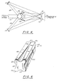
- An example of a movable integrator is shown at 16' in FIGURE 8.
- Integrator 16' is comprised of four mirrors including two opposed and relatively long stationary mirrors 90 and two shorter movable mirrors 92. It will be appreciated that mirrors 92 are shown in two positions including a first position at 92 defining a square format and a second position at 92' defining a rectangular format.
- mirrors 92 may be moved to any other position so that a desired aspect ratio of the illuminated beam may be adjusted.
- the movement of mirrors 92 may be accomplished in a variety of manners.
- mirrors 92 may be actuated by lead screws 94 driven by one or more stepper motors 96 as shown schematically in FIGURE 8.
- Lidar system 72 may comprise any of the known imaging lidar systems such as described in U.S. Patent 4,862,257. However, preferably, lidar system 72 is of the type described in U.S. Application S.N. 565,631 with the laser light beam homogenizer 70 being used in replacement of the beam projectors (identified at 64 and 66 in FIGURE 4 of USSN 565,631).
- a pulsed light source (laser) 74 emits a brief intense illuminating pulse of light with enters laser light beam homogenizer 70 and exits at 76 towards a backscattering medium 78 upon receiving a signal from timing electronics 80 (e.g., a timing generator).
- timing electronics 80 e.g., a timing generator
- a second timing signal is sent from timing generator 80 to a range gated camera 84.
- camera 84 opens a shutter for a brief period whereby reflection or backscattered images of target 82 are formed at the camera output. These reflective images are then viewed on a CRT 86.
Abstract
Description
- This invention relates generally to a device for projecting and reshaping a beam of radiation and an imaging lidar system incorporating this device. More particularly, this invention relates to a new and improved laser light beam homogenizer which transforms a laser beam with spatially inhomogeneous intensity into a beam with a more nearly spatially uniform intensity pattern.
- There is currently a need for discrete devices which expand, reshape and project beams of radiation. An example of an application which may require such a device is the imaging lidar system disclosed in U.S. Patent No. 4,862,257 (assigned to the assignee hereof and incorporated herein by reference) wherein a pulsed light source (laser) projects typically circular pulses of light at a target in a backscattering medium with the reflected light pulses being detected by one or more gated cameras. In certain situations, it may be advantageous to reshape the pulsed light from the original circular cross-section shape to another configuration, generally rectangular or square. This need is particularly important in the imaging lidar system described in U.S. Patent Application Serial No. 565,631 filed August 10, 1990, which is also assigned to the assignee hereof and incorporated herein by reference. Presently, it is difficult to effectively and accurately expand, reshape and project radiation beams such as laser beams.
- Laser beam homogenizers are well known in the art. For example, U.S. Patent No. 4,747,615 to Fan et al (all of the contents of which are incorporated herein by reference). discloses a laser beam homogenizer employing a light tunnel and is described below. As is well known, in order for a light tunnel to have a reasonable geometry (i.e., dimensions), the input laser beam to the light tunnel should have a significant beam divergence angle (herein defined as the angle between the most divergent marginal ray in the light tunnel and the beam axis). In accordance with the laser beam homogenizer of U.S. Patent No. 4,744,615, a lens focuses a laser beam onto a focal point S, which defines a focal plane perpendicular to the optical axis of the laser beam and thereby creates a diverging laser beam with a significant beam divergence angle . The light tunnel receives most of the diverging laser light.
- The entrance of the light tunnel is a square aperture which limits the entering light to a square cross-section and defines the marginal rays of the light in the tunnel. The length L of the tunnel is defined herein for purposes of illustration as a length extending all the way to the focal plane, even when the physical length of the tunnel is less. This is done because a tunnel extending all the way to the focal plane is optically equivalent to a tunnel which extends forward toward the source even farther; or one which does not extend even to the focal plane, so long as the marginal rays in the light tunnel are not changed thereby.
- The beam divergence angle 0 is defined as the angle between the axis and the most divergent marginal ray in the light tunnel. Actually, there is a most divergent marginal ray with respect to each of the reflective sides of the tunnel. With a square tunnel coaxial with the axis, the most divergent marginal ray striking each reflective side of the tunnel strikes the inside front edge of each side at the midpoint of the reflective side, and the beam divergence angle is the same with respect to each of the sides.
- The light tunnel has a length and width such that the diverging laser light portion reflected from the top side and the diverging laser light portion reflected from the bottom side each exactly fills the exit face of the light tunnel. A central portion of the diverging laser light passes through the tunnel without any reflection, while the peripheral portions are reflected.
- Since the rays in each of the reflected portions of the light are still diverging after reflection, the reflected rays may be extended backwards to define virtual focal points or virtual light sources. Actually, two additional virtual focal points or sources are formed by the light which is reflected once from the left and right sides of the light tunnel; and four additional virtual focal points or sources are formed by the light which makes a reflection from each of two adjacent sides of each of the four corners of the tunnel.
- The present invention relates to a laser light beam homogenizer and an imaging lidar system incorporating this laser light beam homogenizer. In accordance with the light beam homogenizer of the present invention, a light beam is focused with an injection optics lens to produce a beam with a significant divergence angle. This beam is presented to an integrator which produce a beam at its exit aperture which has a more uniform illumination and corresponds to the shape of the exit aperture. The uniform illumination beam impinges on control optics which limit the divergence of the uniform beam. The exit aperture is then imaged by projection optics and may be used in a variety of optics applications and finds particular utility in imaging lidar systems such as described in aforementioned USSN 565,631.
- Also, in accordance with the present invention, multiple light sources may be employed to increase total optical power throughout; or to allow multiple wavelengths (i.e., colors of light) to be projected. In accordance with still another feature of the present invention, the integrator may comprise movable sides having internal reflective surfaces such that the aspect ratio of the illuminated beam can be adjusted accordingly.
- The present invention employs injection optics which provide for a shorter overall system length than that of the prior art. Further, the control optics of the present invention may employ slower and less expensive projection optics, or alternatively may employ light sources with higher peak powers than that of the prior art by providing control of the size, location, and shape of beam waists occurring near the projection optics.
- The above-discussed and other features and advantages of the present invention will be appreciated and understood by those of ordinary skill in the art from the following detailed description and drawings.
- Referring now to the drawings, wherein like elements are numbered alike in the several FIGURES:
- FIGURE 1 is a partial schematic view of a laser beam homogenizer in accordance with an embodiment of the present invention;
- FIGURE 2 is a schematic view of the laser beam homogenizer in accordance with another embodiment of the present invention;
- FIGURE 3 is a partial schematic view of the laser beam homogenizer of FIGURE 2 having multiple light sources;
- FIGURE 4 is a partial schematic view of the laser beam homogenizer of FIGURE 2 having both refraction and reflection injection optics;
- FIGURE 5 is a partial schematic view of the laser beam homogenizer of FIGURE 2 having reflection injection optics;
- FIGURE 6 is a perspective view of an integrator for use in the laser beam homogenizer of FIGURE 2 in accordance with an alternate embodiment of the present invention;
- FIGURE 7 is a diagram of an imaging lidar system incorporating the laser beam homogenizer of the present invention; and
- FIGURE 8 is a perspective view of an integrator having movable sides in accordance with the present invention.
- Referring now to FIGURE 1, a laser light beam homogenizer which transforms a laser beam with spatially inhomogeneous intensity into a more nearly spatially uniform intensity pattern is shown generally at 10. In accordance with laser beam homogenizer 10, an
incoming light beam 12 which originates from a laser (not shown) and which diverges very little (i.e., the angle between the marginal rays in the beam and the axis of the beam is very small) is focused by aninjection optics lens 14.Beam 12 is preferably a round collimated laser beam with a divergence angle near zero. The light is then focussed throughlens 14 to alight tunnel 16. However, in order for light tunnel 16 (i.e., an integrator) to have a reasonable geometry (i.e., sufficiently sized dimensions for practical applications), aninput beam 18 tolight tunnel 16 should have a significant beam divergence angle 0 (herein defined as the angle between the most divergent marginal ray 20 inlight tunnel 16 and the beam axis 22).Lens 14 may be a plano-convex lens as shown in FIGURE 1 or a bi-convex lens which focusesbeam 12 onto a focal point S, in order to provideinput beam 18 with beam divergent angle 0. A focal plane 24 defined by focal point S is perpendicular to the optical axis 22 ofbeam 12.Diverging beam 18 is created at focal point S and has a significant beam divergence angle (i.e., angle 6). - Although
lens 14 is shown in FIGURE 1 as a plano-convex lens and is suitable for providing aninput beam 18, it is preferred that the overall length of the system be reduced. Referring now to FIGURE 2,lens 14 is shown as a bi-concave lens (or a double plano-concave lens). Abi-concave lens 14 is preferred because the distance D1, fromlens 14 tointegrator 16 is substantially less than the distance Do (FIGURE 1), from the plano-convex lens 14 tointegrator 16, thereby reducing the overall length of the system. It will be appreciated that thesame input beam 18 with divergence angle 0 is achieved without any degradation in performance. A plano concave lens may also be employed forlens 14, although the bi-concave lens is preferred. - Integrator 16 (i.e., a light tunnel) receives, for purposes of illustration, all of diverging
beam 18 at aninput aperture 26. Since all ofbeam 18 is received, no source intensity is lost due to vignet- ting by integrator 16 (i.e., a reduction in intensity of illumination near the edges ofintegrator 16 ataperture 26 caused by obstruction of light rays frombeam 18 at the edges of aperture 26).Aperture 26 serves as a beam limiting aperture so that the far field illumination pattern is controlled by an acceptance angle ofaperture 26. The acceptance angle is equivalent to divergence angle 0 since, in this illustration, all ofbeam 18 is received byaperture 26. The dimensions ofintegrator 16 are determined by requiring a sufficient number of reflections in the light tunnel to attain the desired uniformity at the exit aperture. -
Integrator 16 internally reflectsbeam 18 to provide a more uniform illumination beam atoutput aperture 28 ofintegrator 16. An output beam 30 (being generally uniform and diverging) is impinged on a beam control optics lens 32. Optics 32 decreases the output divergence angle of beam 30 atexit aperture 28 ofintegrator 16. A controlled beam 34 exiting from optics 32 is imaged on a projection optics lens 36. Lens 36 is employed to direct a projected beam 38 emanating from lens 36. Beam 38 is generally directed at an object or surface for a variety of applications. One such application is an imaging lidar system such as described in U.S. Patent 4,862,257, USSN 565,631 and the imaging lidar system of FIGURE 7. - It is well known from the prior art light tunnels of U.S. Patent 4,744,615, that a plurality of virtual focal points or sources are formed by the light reflected from the internal walls of the light tunnel. It is also known from the prior art that the number of virtual focal points or sources can be varied by changing the length L of
light tunnel 16. The length L oflight tunnel 16 is defined, as described hereinbefore, as a length extending all the way to the focal plane 24, even when the physical length oftunnel 16 is less. Therefore, at theoutput aperture 28 ofintegrator 16, the uniform illumination beam 30 is produced. - In accordance with the present invention, control optics 32 are positioned at the
exit aperture 28 ofintegrator 16 to reduce the divergence of beam 30 exitingintegrator 16. Control optics 32 comprises a plano-convex lens 40 positioned such that the convex surface 41 of lens 40 receives beam 30. Lens 42 receives a less diverging beam 44 from lens 40. Lens 42 is added to control distortion of the light tunnel exit aperture image projected by lens 36. Thus, while the prior art described in Patent 4,744,615 produced a uniform beam at the exit of a light tunnel (i.e., integrator 22) no efforts were made to limit the divergence of thebeam 28. Thus, without control optics 32 projection optic 36 was required to be comprised of relatively fast high quality optics. This requirement for high quality optics leads to significant high cost and maintenance expense. This problem is reduced in the present invention by the lenses 40 and 42 which decrease the divergence angle of beam 30 exitingintegrator 16. A less divergent beam (i.e., beam 34) is now imaged on the projection optics 36 as opposed to the prior art wherein a more divergent beam would have been imaged on lens 36. Further, optics 32 may comprise anamorphic beam forming optics in order to further modify the wavefront of beam 30 exitingintegrator 16 so as to reduce the problems of air breakdown in the beam. The anamorphic beam forming optics reduce the radiance at any intermediate beam circumference. - It will be appreciated that beam 30 at the
output aperture 28 ofintegrator 16 will appear uniform, but on a microscopic level the beam will be highly non uniform due to interference affects. These interference affects arise due to the coherent properties of the laser (i.e., the light source for beam 12). This micro-structure is generally not a concern unless the imaging system used in conjunction with the present invention has a resolution enabling this micro-structure to be seen. In most remote sensing applications, this is usually not the case e.g., generally this micro-structure is averaged out by the imaging system). - The minimum width of
channel integrator 16 is selected in order to reduce the overall length of the system 10. The minimum width ofintegrator 16 is limited by the damage threshold of the coatings used in thechannel integrator 16 and the laser beam diameter. These coatings are both the reflective coatings and anti-reflective coatings.Injection optics 14 are to be chosen such that a minimum of two to three reflections occur for the edge of the divergingbeam 18 for typical laser beam intensity distributions. However, other input beam distributions may require more reflections to achieve adequate uniformity of the beam at the output ofintegrator 16. The uniformity requirements placed on the projected beam as well as the spatial distribution of theinput beam 12 determine the number of needed reflections. It will be appreciated that this can be varied by selecting the appropriate length forintegrator 16 as is well known in the art and described hereinbefore. It should be noted that increasing the number of reflections will increase the uniformity of the output beam 30 as well as makingintegrator 16 less alignment sensitive. This will generally reduce overall system throughput. The reflectance of the interior mirrored faces ofintegrator 16 are a function of incidence angle. After the desired number of reflections is determined, the aspect ratio (length divided by width) ofintegrator 16, and beam divergence angle can be adjusted so as to maximize the throughput of the system. Large injection angles require the projection optics whose focal length to diameter ratio (F#) is very small (approaching unity). Achieving lower F#'s requires higher quality lenses than a system with a higher F#. - Although
beam 12 is described as a single beam from a single source,beam 12 may be a combination of beams. Referring to FIGURE 3 twobeams 12 and 12', each originating from a separate point source (not shown) are directed by lenses 44 and 46 ontoinjection optics lens 14. This allows multiple wavelengths (i.e., colors of light) to be projected. Further, increased total optical power throughput may be achieved by the combination of multiple light sources. It will be appreciated that beams 12 and 12' may originate from a single point source and, through an arrangement of beam splitters and reflective optics, may be impinged onlens 14 in an incoherent fashion. - Referring to FIGURE 4, when homogenizing light beams in which the intensity profile forms a ring-like shape, it may be desirable to divide the
beam 12 into a plurality of sections (preferably four or more) 48, 49, 50 and 51. This may be accomplished with a pyramidal beam reflector 52 whereby beams 48-51 are directed by mirrors 54 onto lens 14 (FIGURE 2). The peak intensity region of each beam 48-51 passes essentially unreflected down the center ofintegrator 16 with the lower intensity portions reflected from the sides ofintegrator 16. - Referring to FIGURE 5, it may be desirable to preserve the polarization state of the
incoming light beam 12. This may be accomplished with still another embodiment of the present invention using axisymmetric reflective optics. In accordance with this axisymmetric reflective optics embodiment,beam 12 is reflected off a first surface 56 onto surfaces 58 and 59 and then directed onto surfaces 60 and 61, respectively. Thereafter,beam 12 is reflected onto surface 62 which images the divergingbeam 18 ontoaperture 26 ofintegrator 16. Preferably, at least six axisymmetric reflective optics are used. This may also be accomplished with low birefringence refracting optics as is well known in the art. - Although
integrator 16 is shown in FIGURES 1-5 as having plane parallel sides aligned to the optical axis 22, referring to FIGURE 6,integrator 16 may also have acurved recess 64 at about the center of in eachside 66.Curved recess 64 is tapered fromaperture 28 down towardaperture 26. This will allow adjustment of the uniformity of thebeam exiting integrator 16. -
Integrator 16 may be formed from a single solid glass or crystalline component and coated on its sides with a reflective coating and on its ends with an anti-reflection coating as shown in FIGURE 6; or it may be formed from a number (preferably four) of independent mirrors which are joined at their edges or are movable. With movable sides, the aspect ratio of the illuminated beam can be adjusted accordingly. An example of a movable integrator is shown at 16' in FIGURE 8. Integrator 16' is comprised of four mirrors including two opposed and relatively longstationary mirrors 90 and two shorter movable mirrors 92. It will be appreciated that mirrors 92 are shown in two positions including a first position at 92 defining a square format and a second position at 92' defining a rectangular format. Of course, mirrors 92 may be moved to any other position so that a desired aspect ratio of the illuminated beam may be adjusted. The movement ofmirrors 92 may be accomplished in a variety of manners. For example, mirrors 92 may be actuated bylead screws 94 driven by one ormore stepper motors 96 as shown schematically in FIGURE 8. - Referring now to FIGURE 7 and in accordance with an important application of the present invention, the laser light beam homogenizer as described in any of the embodiments of FIGURES 1-6 is shown at 70 having been incorporated into an
imaging lidar system 72.Lidar system 72 may comprise any of the known imaging lidar systems such as described in U.S. Patent 4,862,257. However, preferably,lidar system 72 is of the type described in U.S. Application S.N. 565,631 with the laserlight beam homogenizer 70 being used in replacement of the beam projectors (identified at 64 and 66 in FIGURE 4 of USSN 565,631). In accordance with the well known operation of animaging lidar system 72, a pulsed light source (laser) 74 emits a brief intense illuminating pulse of light with enters laserlight beam homogenizer 70 and exits at 76 towards abackscattering medium 78 upon receiving a signal from timing electronics 80 (e.g., a timing generator). It will be appreciated that the small diameter laser beams emitted bylaser 74 will be converted byhomogenizer 70 from a non-uniform intensity distribution of a typically round beam into a uniformly bright rectangular beam. After a time delay corresponding to the round trip propagation time of the light traveling fromlaser 74 to anobject 82 inbackscattering medium 78 and back up again to theimaging system 72, a second timing signal is sent from timinggenerator 80 to a range gated camera 84. Upon receipt of this signal, camera 84 opens a shutter for a brief period whereby reflection or backscattered images oftarget 82 are formed at the camera output. These reflective images are then viewed on aCRT 86. - While preferred embodiments have been shown and described, various modifications and substitutions may be made thereto without departing from the spirit and scope of the invention. Accordingly, it is to be understood that the present invention has been described by way of illustrations and not limitations.
Claims (27)
Applications Claiming Priority (2)
| Application Number | Priority Date | Filing Date | Title |
|---|---|---|---|
| US750572 | 1985-07-01 | ||
| US07/750,572 US5303084A (en) | 1991-08-27 | 1991-08-27 | Laser light beam homogenizer and imaging lidar system incorporating same |
Publications (3)
| Publication Number | Publication Date |
|---|---|
| EP0493365A2 true EP0493365A2 (en) | 1992-07-01 |
| EP0493365A3 EP0493365A3 (en) | 1993-09-29 |
| EP0493365B1 EP0493365B1 (en) | 1997-05-28 |
Family
ID=25018400
Family Applications (1)
| Application Number | Title | Priority Date | Filing Date |
|---|---|---|---|
| EP92103826A Expired - Lifetime EP0493365B1 (en) | 1991-08-27 | 1992-03-06 | Laser light beam homogenizer and imaging lidar system incorporating same |
Country Status (4)
| Country | Link |
|---|---|
| US (2) | US5303084A (en) |
| EP (1) | EP0493365B1 (en) |
| AT (1) | ATE153778T1 (en) |
| DE (1) | DE69219907D1 (en) |
Cited By (8)
| Publication number | Priority date | Publication date | Assignee | Title |
|---|---|---|---|---|
| DE4341553C1 (en) * | 1993-12-07 | 1995-04-27 | Fraunhofer Ges Forschung | Device for homogenising the light distribution of a laser beam |
| GB2329036A (en) * | 1997-09-05 | 1999-03-10 | Sharp Kk | Optical system for redistributing optical extent and illumination source |
| WO2000042472A1 (en) * | 1999-01-14 | 2000-07-20 | 3M Innovative Properties Company | Method for patterning thin films |
| US6155688A (en) * | 1997-09-05 | 2000-12-05 | Sharp Kabushiki Kaisha | Dark field projection display |
| DE19940305A1 (en) * | 1999-08-25 | 2001-03-22 | Zeiss Carl Jena Gmbh | Manufacturing method for a light integrator, a light integrator and a use thereof |
| US6341876B1 (en) | 1997-02-19 | 2002-01-29 | Digital Projection Limited | Illumination system |
| EP1306697A1 (en) * | 1994-06-28 | 2003-05-02 | Corning Incorporated | Apparatus for uniformly illuminating a light valve |
| DE102004049964A1 (en) * | 2004-10-14 | 2006-04-20 | Carl Zeiss Jena Gmbh | Production of a plastic hollow integrator for light projection, involves simultaneous injection moulding of plastic elements, simultaneous metallisation by vapour deposition and then fitting the elements together |
Families Citing this family (75)
| Publication number | Priority date | Publication date | Assignee | Title |
|---|---|---|---|---|
| US6392689B1 (en) * | 1991-02-21 | 2002-05-21 | Eugene Dolgoff | System for displaying moving images pseudostereoscopically |
| JP3151581B2 (en) * | 1992-12-21 | 2001-04-03 | 株式会社トプコン | Lightwave rangefinder |
| JPH09234579A (en) * | 1996-02-28 | 1997-09-09 | Semiconductor Energy Lab Co Ltd | Laser beam irradiating device |
| US6053615A (en) * | 1996-08-02 | 2000-04-25 | In Focus Systems, Inc. | Image projector with polarization conversion system |
| US5825464A (en) * | 1997-01-03 | 1998-10-20 | Lockheed Corp | Calibration system and method for lidar systems |
| KR19980068378A (en) * | 1997-02-19 | 1998-10-15 | 김광호 | Optical device of the liquid crystal projector |
| CA2348386A1 (en) * | 1998-10-30 | 2000-05-11 | Helen Gourley | Projector system with light pipe optics |
| EP1102041A1 (en) * | 1999-11-20 | 2001-05-23 | Reto T. Meili | Measurement method and system for carrying out the method |
| US6517210B2 (en) | 2000-04-21 | 2003-02-11 | Infocus Corporation | Shortened asymmetrical tunnel for spatially integrating light |
| US6419365B1 (en) | 2000-04-21 | 2002-07-16 | Infocus Corporation | Asymmetrical tunnel for spatially integrating light |
| US6560397B1 (en) * | 2000-10-30 | 2003-05-06 | Fraunhofer, Usa | Optical system for varying the beam width using non-imaging optics |
| US6719429B2 (en) | 2001-03-30 | 2004-04-13 | Infocus Corporation | Anamorphic illumination of micro-electromechanical display devices employed in multimedia projectors |
| WO2002086593A2 (en) | 2001-04-23 | 2002-10-31 | Willden Dee E | Lensless laser focusing device |
| DE10136611C1 (en) * | 2001-07-23 | 2002-11-21 | Jenoptik Laserdiode Gmbh | Optical device, for laser light emitted by laser diode device, has collimation optical element and homogenizing element using multiple reflection of laser beam |
| JPWO2003049175A1 (en) * | 2001-12-07 | 2005-04-21 | ソニー株式会社 | Light irradiation apparatus and laser annealing apparatus |
| US6903859B2 (en) * | 2001-12-07 | 2005-06-07 | Micronic Laser Systems Ab | Homogenizer |
| TWI332682B (en) * | 2002-09-19 | 2010-11-01 | Semiconductor Energy Lab | Beam homogenizer and laser irradiation apparatus and method of manufacturing semiconductor device |
| GB2395289A (en) * | 2002-11-11 | 2004-05-19 | Qinetiq Ltd | Structured light generator |
| JP3767544B2 (en) * | 2002-11-25 | 2006-04-19 | セイコーエプソン株式会社 | Optical device, illumination device, and projector |
| IL154479A0 (en) * | 2003-02-16 | 2003-09-17 | Elbit Systems Ltd | Laser gated intensified ccd |
| US7327916B2 (en) * | 2003-03-11 | 2008-02-05 | Semiconductor Energy Laboratory Co., Ltd. | Beam Homogenizer, laser irradiation apparatus, and method of manufacturing a semiconductor device |
| SG137674A1 (en) | 2003-04-24 | 2007-12-28 | Semiconductor Energy Lab | Beam homogenizer, laser irradiation apparatus, and method for manufacturing semiconductor device |
| US7245802B2 (en) * | 2003-08-04 | 2007-07-17 | Semiconductor Energy Laboratory Co., Ltd. | Beam homogenizer, laser irradiation apparatus and method for manufacturing semiconductor device |
| US7169630B2 (en) * | 2003-09-30 | 2007-01-30 | Semiconductor Energy Laboratory Co., Ltd. | Beam homogenizer, laser irradiation apparatus, and method for manufacturing semiconductor device |
| DE102004046373A1 (en) * | 2004-09-24 | 2006-03-30 | Carl Zeiss Jena Gmbh | Matrix-type light integrator for LCD or DLP projectors has wedges of reflecting foil forming channels gradually increasing in cross-section from input face to output face |
| US20060082888A1 (en) * | 2004-10-19 | 2006-04-20 | Andrew Huibers | Optically reconfigurable light integrator in display systems using spatial light modulators |
| US7664365B2 (en) * | 2004-10-27 | 2010-02-16 | Semiconductor Energy Laboratory Co., Ltd. | Beam homogenizer, and laser irradiation method, laser irradiation apparatus, and laser annealing method of non-single crystalline semiconductor film using the same |
| US20070153392A1 (en) * | 2005-01-21 | 2007-07-05 | Meritt Reynolds | Apparatus and method for illumination of light valves |
| DE102005005355B4 (en) * | 2005-02-05 | 2018-05-09 | Adc Automotive Distance Control Systems Gmbh | Device for shaping a light beam |
| US7434946B2 (en) * | 2005-06-17 | 2008-10-14 | Texas Instruments Incorporated | Illumination system with integrated heat dissipation device for use in display systems employing spatial light modulators |
| US7777955B2 (en) * | 2005-07-29 | 2010-08-17 | Optical Research Associates | Rippled mixers for uniformity and color mixing |
| US7657147B2 (en) * | 2006-03-02 | 2010-02-02 | Solar Light Company, Inc. | Sunlight simulator apparatus |
| US8558993B2 (en) | 2010-05-21 | 2013-10-15 | The National Institute of Standards and Technology, as Presented by the Secretary of Commerce | Optical frequency comb-based coherent LIDAR |
| CN102650738A (en) * | 2011-02-25 | 2012-08-29 | 中强光电股份有限公司 | Lighting system and projecting device |
| US20120249781A1 (en) * | 2011-04-04 | 2012-10-04 | Richard Vollmerhausen | Method consisting of pulsing a laser communicating with a gated-sensor so as to reduce speckle, reduce scintillation, improve laser beam uniformity and improve eye safety in laser range gated imagery |
| TWI529020B (en) * | 2013-12-02 | 2016-04-11 | 財團法人工業技術研究院 | Beam diffusing module and beam generating system |
| CN112117359A (en) | 2014-01-06 | 2020-12-22 | 亮锐控股有限公司 | Thin LED flash for camera |
| US9720415B2 (en) | 2015-11-04 | 2017-08-01 | Zoox, Inc. | Sensor-based object-detection optimization for autonomous vehicles |
| US10359507B2 (en) | 2016-12-30 | 2019-07-23 | Panosense Inc. | Lidar sensor assembly calibration based on reference surface |
| US10742088B2 (en) | 2016-12-30 | 2020-08-11 | Panosense Inc. | Support assembly for rotating body |
| US10830878B2 (en) | 2016-12-30 | 2020-11-10 | Panosense Inc. | LIDAR system |
| US10591740B2 (en) | 2016-12-30 | 2020-03-17 | Panosense Inc. | Lens assembly for a LIDAR system |
| US10109183B1 (en) | 2016-12-30 | 2018-10-23 | Panosense Inc. | Interface for transferring data between a non-rotating body and a rotating body |
| US10048358B2 (en) | 2016-12-30 | 2018-08-14 | Panosense Inc. | Laser power calibration and correction |
| US10122416B2 (en) | 2016-12-30 | 2018-11-06 | Panosense Inc. | Interface for transferring power and data between a non-rotating body and a rotating body |
| US10295660B1 (en) | 2016-12-30 | 2019-05-21 | Panosense Inc. | Aligning optical components in LIDAR systems |
| US10942257B2 (en) | 2016-12-31 | 2021-03-09 | Innovusion Ireland Limited | 2D scanning high precision LiDAR using combination of rotating concave mirror and beam steering devices |
| US11009605B2 (en) | 2017-01-05 | 2021-05-18 | Innovusion Ireland Limited | MEMS beam steering and fisheye receiving lens for LiDAR system |
| CN110494771B (en) * | 2017-02-08 | 2022-01-18 | 巨跃控股有限责任公司 | Light steering and focusing by dielectrophoresis |
| DE102017213466A1 (en) * | 2017-08-03 | 2019-02-07 | Zumtobel Lighting Gmbh | Light mixed conductor |
| DE102017213462A1 (en) * | 2017-08-03 | 2019-02-07 | Zumtobel Lighting Gmbh | Light mixed conductor |
| US10338594B2 (en) * | 2017-03-13 | 2019-07-02 | Nio Usa, Inc. | Navigation of autonomous vehicles to enhance safety under one or more fault conditions |
| US11487128B2 (en) | 2017-03-16 | 2022-11-01 | Fastree3D Sa | Apparatus for beam shaping the pulsed laser emission of a remote sensing operating at wavelengths in the retinal hazard region |
| US10556585B1 (en) | 2017-04-13 | 2020-02-11 | Panosense Inc. | Surface normal determination for LIDAR range samples by detecting probe pulse stretching |
| US10423162B2 (en) | 2017-05-08 | 2019-09-24 | Nio Usa, Inc. | Autonomous vehicle logic to identify permissioned parking relative to multiple classes of restricted parking |
| US10369974B2 (en) | 2017-07-14 | 2019-08-06 | Nio Usa, Inc. | Control and coordination of driverless fuel replenishment for autonomous vehicles |
| US10710633B2 (en) | 2017-07-14 | 2020-07-14 | Nio Usa, Inc. | Control of complex parking maneuvers and autonomous fuel replenishment of driverless vehicles |
| US11493601B2 (en) | 2017-12-22 | 2022-11-08 | Innovusion, Inc. | High density LIDAR scanning |
| US11675050B2 (en) | 2018-01-09 | 2023-06-13 | Innovusion, Inc. | LiDAR detection systems and methods |
| US11022971B2 (en) | 2018-01-16 | 2021-06-01 | Nio Usa, Inc. | Event data recordation to identify and resolve anomalies associated with control of driverless vehicles |
| US11808888B2 (en) | 2018-02-23 | 2023-11-07 | Innovusion, Inc. | Multi-wavelength pulse steering in LiDAR systems |
| WO2019241396A1 (en) | 2018-06-15 | 2019-12-19 | Innovusion Ireland Limited | Lidar systems and methods for focusing on ranges of interest |
| CN114114606A (en) | 2018-11-14 | 2022-03-01 | 图达通爱尔兰有限公司 | LIDAR system and method using polygon mirror |
| US11543528B2 (en) | 2018-11-30 | 2023-01-03 | University Of South Florida | System and method of dynamic light source control |
| US11675055B2 (en) | 2019-01-10 | 2023-06-13 | Innovusion, Inc. | LiDAR systems and methods with beam steering and wide angle signal detection |
| US11486970B1 (en) | 2019-02-11 | 2022-11-01 | Innovusion, Inc. | Multiple beam generation from a single source beam for use with a LiDAR system |
| CN110058335A (en) * | 2019-04-30 | 2019-07-26 | 西安炬光科技股份有限公司 | The implementation method of optical element, therapeutic equipment and hot spot transformation |
| US11556000B1 (en) | 2019-08-22 | 2023-01-17 | Red Creamery Llc | Distally-actuated scanning mirror |
| DE102020117789A1 (en) | 2020-07-06 | 2022-01-13 | Bartenbach Holding Gmbh | lamp |
| DE102020214473A1 (en) | 2020-11-18 | 2022-05-19 | Robert Bosch Gesellschaft mit beschränkter Haftung | LiDAR system |
| EP4260086A1 (en) | 2021-03-01 | 2023-10-18 | Innovusion, Inc. | Fiber-based transmitter and receiver channels of light detection and ranging systems |
| US11555895B2 (en) | 2021-04-20 | 2023-01-17 | Innovusion, Inc. | Dynamic compensation to polygon and motor tolerance using galvo control profile |
| US11614521B2 (en) | 2021-04-21 | 2023-03-28 | Innovusion, Inc. | LiDAR scanner with pivot prism and mirror |
| EP4305450A1 (en) | 2021-04-22 | 2024-01-17 | Innovusion, Inc. | A compact lidar design with high resolution and ultra-wide field of view |
| EP4314884A1 (en) | 2021-05-21 | 2024-02-07 | Innovusion, Inc. | Movement profiles for smart scanning using galvonometer mirror inside lidar scanner |
Citations (7)
| Publication number | Priority date | Publication date | Assignee | Title |
|---|---|---|---|---|
| EP0121069A2 (en) * | 1983-03-31 | 1984-10-10 | International Business Machines Corporation | Reflecting system for improving the uniformity of a light beam |
| JPS60150025A (en) * | 1984-01-18 | 1985-08-07 | Nec Corp | Optical superposition system for laser beam |
| DE3509421A1 (en) * | 1984-03-16 | 1985-09-26 | Gianfranco Prof. Rom/Roma Vitali | Improved device for homogenising and diffusing laser beams |
| FR2578691A1 (en) * | 1985-03-06 | 1986-09-12 | Bouchlaghem Daniel | Laser generator with adjustable power |
| US4862257A (en) * | 1988-07-07 | 1989-08-29 | Kaman Aerospace Corporation | Imaging lidar system |
| GB2228344A (en) * | 1989-02-17 | 1990-08-22 | Mezhotraslevoi Nt Komplex Mikr | Ophthalmological lasers |
| WO1991004829A1 (en) * | 1989-10-06 | 1991-04-18 | B.V. Optische Industrie 'de Oude Delft' | Device for providing a beam of laser radiation having a homogeneous energy distribution |
Family Cites Families (10)
| Publication number | Priority date | Publication date | Assignee | Title |
|---|---|---|---|---|
| US3076377A (en) * | 1958-10-06 | 1963-02-05 | Dietzgen Co Eugene | Optical projector system |
| US3170980A (en) * | 1962-05-09 | 1965-02-23 | Rca Corp | Optical tunnel system |
| US3476463A (en) * | 1965-05-11 | 1969-11-04 | Perkin Elmer Corp | Coherent light optical system yielding an output beam of desired intensity distribution at a desired equiphase surface |
| US4195913A (en) * | 1977-11-09 | 1980-04-01 | Spawr Optical Research, Inc. | Optical integration with screw supports |
| US4327972A (en) * | 1979-10-22 | 1982-05-04 | Coulter Electronics, Inc. | Redirecting surface for desired intensity profile |
| US4744615A (en) * | 1986-01-29 | 1988-05-17 | International Business Machines Corporation | Laser beam homogenizer |
| KR950011145B1 (en) * | 1988-06-27 | 1995-09-28 | 도요 세이깡 가부시끼가시야 | Label applying apparatu of rotary blow molding machine |
| US5109465A (en) * | 1990-01-16 | 1992-04-28 | Summit Technology, Inc. | Beam homogenizer |
| US5054869A (en) * | 1990-03-02 | 1991-10-08 | Axiom Analytical, Inc. | Light pipe system having maximum radiation throughput |
| US5231401A (en) * | 1990-08-10 | 1993-07-27 | Kaman Aerospace Corporation | Imaging lidar system |
-
1991
- 1991-08-27 US US07/750,572 patent/US5303084A/en not_active Expired - Lifetime
-
1992
- 1992-03-06 DE DE69219907T patent/DE69219907D1/en not_active Expired - Lifetime
- 1992-03-06 EP EP92103826A patent/EP0493365B1/en not_active Expired - Lifetime
- 1992-03-06 AT AT92103826T patent/ATE153778T1/en not_active IP Right Cessation
-
1993
- 1993-09-14 US US08/096,923 patent/US5335070A/en not_active Expired - Lifetime
Patent Citations (7)
| Publication number | Priority date | Publication date | Assignee | Title |
|---|---|---|---|---|
| EP0121069A2 (en) * | 1983-03-31 | 1984-10-10 | International Business Machines Corporation | Reflecting system for improving the uniformity of a light beam |
| JPS60150025A (en) * | 1984-01-18 | 1985-08-07 | Nec Corp | Optical superposition system for laser beam |
| DE3509421A1 (en) * | 1984-03-16 | 1985-09-26 | Gianfranco Prof. Rom/Roma Vitali | Improved device for homogenising and diffusing laser beams |
| FR2578691A1 (en) * | 1985-03-06 | 1986-09-12 | Bouchlaghem Daniel | Laser generator with adjustable power |
| US4862257A (en) * | 1988-07-07 | 1989-08-29 | Kaman Aerospace Corporation | Imaging lidar system |
| GB2228344A (en) * | 1989-02-17 | 1990-08-22 | Mezhotraslevoi Nt Komplex Mikr | Ophthalmological lasers |
| WO1991004829A1 (en) * | 1989-10-06 | 1991-04-18 | B.V. Optische Industrie 'de Oude Delft' | Device for providing a beam of laser radiation having a homogeneous energy distribution |
Non-Patent Citations (1)
| Title |
|---|
| PATENT ABSTRACTS OF JAPAN vol. 9, no. 323 (P-414)(2046) 18 December 1985 & JP-A-60 150 025 ( NIPPON DENKI K. K. ) 7 August 1985 * |
Cited By (11)
| Publication number | Priority date | Publication date | Assignee | Title |
|---|---|---|---|---|
| DE4341553C1 (en) * | 1993-12-07 | 1995-04-27 | Fraunhofer Ges Forschung | Device for homogenising the light distribution of a laser beam |
| EP1306697A1 (en) * | 1994-06-28 | 2003-05-02 | Corning Incorporated | Apparatus for uniformly illuminating a light valve |
| US6341876B1 (en) | 1997-02-19 | 2002-01-29 | Digital Projection Limited | Illumination system |
| GB2329036A (en) * | 1997-09-05 | 1999-03-10 | Sharp Kk | Optical system for redistributing optical extent and illumination source |
| US6155688A (en) * | 1997-09-05 | 2000-12-05 | Sharp Kabushiki Kaisha | Dark field projection display |
| WO2000042472A1 (en) * | 1999-01-14 | 2000-07-20 | 3M Innovative Properties Company | Method for patterning thin films |
| US6203952B1 (en) | 1999-01-14 | 2001-03-20 | 3M Innovative Properties Company | Imaged article on polymeric substrate |
| US6399258B2 (en) | 1999-01-14 | 2002-06-04 | 3M Innovative Properties Company | Method for patterning thin films |
| DE19940305A1 (en) * | 1999-08-25 | 2001-03-22 | Zeiss Carl Jena Gmbh | Manufacturing method for a light integrator, a light integrator and a use thereof |
| DE19940305C2 (en) * | 1999-08-25 | 2003-06-18 | Zeiss Carl Jena Gmbh | Manufacturing process for a light integrator, a light integrator and a use thereof |
| DE102004049964A1 (en) * | 2004-10-14 | 2006-04-20 | Carl Zeiss Jena Gmbh | Production of a plastic hollow integrator for light projection, involves simultaneous injection moulding of plastic elements, simultaneous metallisation by vapour deposition and then fitting the elements together |
Also Published As
| Publication number | Publication date |
|---|---|
| EP0493365B1 (en) | 1997-05-28 |
| ATE153778T1 (en) | 1997-06-15 |
| US5335070A (en) | 1994-08-02 |
| EP0493365A3 (en) | 1993-09-29 |
| US5303084A (en) | 1994-04-12 |
| DE69219907D1 (en) | 1997-07-03 |
Similar Documents
| Publication | Publication Date | Title |
|---|---|---|
| US5335070A (en) | Laser light beam homogenizer and imaging lidar system incorporating same | |
| US4939630A (en) | Illumination optical apparatus | |
| US4508422A (en) | Optical scanning system | |
| US9939633B2 (en) | Flat field telecentric scanner with diffraction limited performance | |
| US3380358A (en) | Range gated imaging system | |
| US10754234B2 (en) | Projection device | |
| US7460215B2 (en) | Method and device for optically measuring distance or speed | |
| JPH08248349A (en) | Laser pulse extension device | |
| KR102639046B1 (en) | Optical array, LiDAR system, and actuator for LiDAR system | |
| JP2008530786A (en) | A device for projecting a reduced image of a photomask using a Schwarzschild objective | |
| KR20000070180A (en) | Projection light source | |
| US11639986B2 (en) | Optical device for a distance measurement device according to the LIDAR principle | |
| CN216434623U (en) | Optical lens equipment and adjustable uniform light source system | |
| US11662578B2 (en) | Image display device | |
| JPS6212462B2 (en) | ||
| KR20070084600A (en) | Optical system and corresponding optical element | |
| JPS63114186A (en) | Lighting apparatus | |
| JP3981608B2 (en) | Dual beam optical device | |
| CN112925104B (en) | Angle array light homogenizing rod | |
| CN115754978B (en) | Optical axis parallel adjustment method based on laser emission system and telescope receiving system | |
| KR102425179B1 (en) | Line beam forming device | |
| US20230314791A1 (en) | Scanner laser optics for lidar | |
| US11619709B2 (en) | Optical system to reduce local internal backscatter | |
| CN115685529A (en) | Optical delay line based on reflecting lens and application thereof | |
| JPS63113412A (en) | Mask lighting optical system |
Legal Events
| Date | Code | Title | Description |
|---|---|---|---|
| PUAI | Public reference made under article 153(3) epc to a published international application that has entered the european phase |
Free format text: ORIGINAL CODE: 0009012 |
|
| AK | Designated contracting states |
Kind code of ref document: A2 Designated state(s): AT BE CH DE DK ES FR GB GR IT LI LU MC NL PT SE |
|
| PUAL | Search report despatched |
Free format text: ORIGINAL CODE: 0009013 |
|
| AK | Designated contracting states |
Kind code of ref document: A3 Designated state(s): AT BE CH DE DK ES FR GB GR IT LI LU MC NL PT SE |
|
| 17P | Request for examination filed |
Effective date: 19940121 |
|
| 17Q | First examination report despatched |
Effective date: 19951005 |
|
| GRAG | Despatch of communication of intention to grant |
Free format text: ORIGINAL CODE: EPIDOS AGRA |
|
| GRAH | Despatch of communication of intention to grant a patent |
Free format text: ORIGINAL CODE: EPIDOS IGRA |
|
| GRAH | Despatch of communication of intention to grant a patent |
Free format text: ORIGINAL CODE: EPIDOS IGRA |
|
| GRAA | (expected) grant |
Free format text: ORIGINAL CODE: 0009210 |
|
| AK | Designated contracting states |
Kind code of ref document: B1 Designated state(s): AT BE CH DE DK ES FR GB GR IT LI LU MC NL PT SE |
|
| PG25 | Lapsed in a contracting state [announced via postgrant information from national office to epo] |
Ref country code: IT Free format text: LAPSE BECAUSE OF FAILURE TO SUBMIT A TRANSLATION OF THE DESCRIPTION OR TO PAY THE FEE WITHIN THE PRESCRIBED TIME-LIMIT;WARNING: LAPSES OF ITALIAN PATENTS WITH EFFECTIVE DATE BEFORE 2007 MAY HAVE OCCURRED AT ANY TIME BEFORE 2007. THE CORRECT EFFECTIVE DATE MAY BE DIFFERENT FROM THE ONE RECORDED. Effective date: 19970528 Ref country code: NL Free format text: LAPSE BECAUSE OF FAILURE TO SUBMIT A TRANSLATION OF THE DESCRIPTION OR TO PAY THE FEE WITHIN THE PRESCRIBED TIME-LIMIT Effective date: 19970528 Ref country code: CH Effective date: 19970528 Ref country code: BE Effective date: 19970528 Ref country code: FR Free format text: THE PATENT HAS BEEN ANNULLED BY A DECISION OF A NATIONAL AUTHORITY Effective date: 19970528 Ref country code: AT Effective date: 19970528 Ref country code: ES Free format text: THE PATENT HAS BEEN ANNULLED BY A DECISION OF A NATIONAL AUTHORITY Effective date: 19970528 Ref country code: GR Free format text: LAPSE BECAUSE OF FAILURE TO SUBMIT A TRANSLATION OF THE DESCRIPTION OR TO PAY THE FEE WITHIN THE PRESCRIBED TIME-LIMIT Effective date: 19970528 Ref country code: DK Effective date: 19970528 Ref country code: LI Effective date: 19970528 |
|
| REF | Corresponds to: |
Ref document number: 153778 Country of ref document: AT Date of ref document: 19970615 Kind code of ref document: T |
|
| REG | Reference to a national code |
Ref country code: CH Ref legal event code: EP |
|
| REF | Corresponds to: |
Ref document number: 69219907 Country of ref document: DE Date of ref document: 19970703 |
|
| ET | Fr: translation filed | ||
| PG25 | Lapsed in a contracting state [announced via postgrant information from national office to epo] |
Ref country code: PT Effective date: 19970828 |
|
| PG25 | Lapsed in a contracting state [announced via postgrant information from national office to epo] |
Ref country code: DE Effective date: 19970829 |
|
| NLV1 | Nl: lapsed or annulled due to failure to fulfill the requirements of art. 29p and 29m of the patents act | ||
| REG | Reference to a national code |
Ref country code: CH Ref legal event code: PL |
|
| PG25 | Lapsed in a contracting state [announced via postgrant information from national office to epo] |
Ref country code: LU Free format text: LAPSE BECAUSE OF NON-PAYMENT OF DUE FEES Effective date: 19980306 Ref country code: GB Free format text: LAPSE BECAUSE OF NON-PAYMENT OF DUE FEES Effective date: 19980306 |
|
| PG25 | Lapsed in a contracting state [announced via postgrant information from national office to epo] |
Ref country code: SE Free format text: LAPSE BECAUSE OF NON-PAYMENT OF DUE FEES Effective date: 19980307 |
|
| PLBE | No opposition filed within time limit |
Free format text: ORIGINAL CODE: 0009261 |
|
| STAA | Information on the status of an ep patent application or granted ep patent |
Free format text: STATUS: NO OPPOSITION FILED WITHIN TIME LIMIT |
|
| 26N | No opposition filed | ||
| PG25 | Lapsed in a contracting state [announced via postgrant information from national office to epo] |
Ref country code: MC Free format text: LAPSE BECAUSE OF NON-PAYMENT OF DUE FEES Effective date: 19980930 |
|
| GBPC | Gb: european patent ceased through non-payment of renewal fee |
Effective date: 19980306 |
|
| EUG | Se: european patent has lapsed |
Ref document number: 92103826.1 |
|
| REG | Reference to a national code |
Ref country code: FR Ref legal event code: ST |