EP0492006A1 - Lowering device of the free edge of vehicle soft top or similar - Google Patents
Lowering device of the free edge of vehicle soft top or similar Download PDFInfo
- Publication number
- EP0492006A1 EP0492006A1 EP19900250338 EP90250338A EP0492006A1 EP 0492006 A1 EP0492006 A1 EP 0492006A1 EP 19900250338 EP19900250338 EP 19900250338 EP 90250338 A EP90250338 A EP 90250338A EP 0492006 A1 EP0492006 A1 EP 0492006A1
- Authority
- EP
- European Patent Office
- Prior art keywords
- engagement
- hold
- locking position
- slot
- receiving slot
- Prior art date
- Legal status (The legal status is an assumption and is not a legal conclusion. Google has not performed a legal analysis and makes no representation as to the accuracy of the status listed.)
- Granted
Links
Images


Classifications
-
- B—PERFORMING OPERATIONS; TRANSPORTING
- B60—VEHICLES IN GENERAL
- B60J—WINDOWS, WINDSCREENS, NON-FIXED ROOFS, DOORS, OR SIMILAR DEVICES FOR VEHICLES; REMOVABLE EXTERNAL PROTECTIVE COVERINGS SPECIALLY ADAPTED FOR VEHICLES
- B60J7/00—Non-fixed roofs; Roofs with movable panels, e.g. rotary sunroofs
- B60J7/185—Locking arrangements
- B60J7/1851—Locking arrangements for locking the foldable soft- or hard-top to the windshield header
-
- E—FIXED CONSTRUCTIONS
- E05—LOCKS; KEYS; WINDOW OR DOOR FITTINGS; SAFES
- E05C—BOLTS OR FASTENING DEVICES FOR WINGS, SPECIALLY FOR DOORS OR WINDOWS
- E05C5/00—Fastening devices with bolts moving otherwise than only rectilinearly and only pivotally or rotatively
-
- E—FIXED CONSTRUCTIONS
- E05—LOCKS; KEYS; WINDOW OR DOOR FITTINGS; SAFES
- E05C—BOLTS OR FASTENING DEVICES FOR WINGS, SPECIALLY FOR DOORS OR WINDOWS
- E05C9/00—Arrangements of simultaneously actuated bolts or other securing devices at well-separated positions on the same wing
- E05C9/04—Arrangements of simultaneously actuated bolts or other securing devices at well-separated positions on the same wing with two sliding bars moved in opposite directions when fastening or unfastening
- E05C9/043—Arrangements of simultaneously actuated bolts or other securing devices at well-separated positions on the same wing with two sliding bars moved in opposite directions when fastening or unfastening with crank pins and connecting rods
-
- E—FIXED CONSTRUCTIONS
- E05—LOCKS; KEYS; WINDOW OR DOOR FITTINGS; SAFES
- E05B—LOCKS; ACCESSORIES THEREFOR; HANDCUFFS
- E05B51/00—Operating or controlling locks or other fastening devices by other non-mechanical means
- E05B51/02—Operating or controlling locks or other fastening devices by other non-mechanical means by pneumatic or hydraulic means
-
- Y—GENERAL TAGGING OF NEW TECHNOLOGICAL DEVELOPMENTS; GENERAL TAGGING OF CROSS-SECTIONAL TECHNOLOGIES SPANNING OVER SEVERAL SECTIONS OF THE IPC; TECHNICAL SUBJECTS COVERED BY FORMER USPC CROSS-REFERENCE ART COLLECTIONS [XRACs] AND DIGESTS
- Y10—TECHNICAL SUBJECTS COVERED BY FORMER USPC
- Y10S—TECHNICAL SUBJECTS COVERED BY FORMER USPC CROSS-REFERENCE ART COLLECTIONS [XRACs] AND DIGESTS
- Y10S292/00—Closure fasteners
- Y10S292/05—Automobile top latches
-
- Y—GENERAL TAGGING OF NEW TECHNOLOGICAL DEVELOPMENTS; GENERAL TAGGING OF CROSS-SECTIONAL TECHNOLOGIES SPANNING OVER SEVERAL SECTIONS OF THE IPC; TECHNICAL SUBJECTS COVERED BY FORMER USPC CROSS-REFERENCE ART COLLECTIONS [XRACs] AND DIGESTS
- Y10—TECHNICAL SUBJECTS COVERED BY FORMER USPC
- Y10S—TECHNICAL SUBJECTS COVERED BY FORMER USPC CROSS-REFERENCE ART COLLECTIONS [XRACs] AND DIGESTS
- Y10S292/00—Closure fasteners
- Y10S292/43—Rear deck lid latches
-
- Y—GENERAL TAGGING OF NEW TECHNOLOGICAL DEVELOPMENTS; GENERAL TAGGING OF CROSS-SECTIONAL TECHNOLOGIES SPANNING OVER SEVERAL SECTIONS OF THE IPC; TECHNICAL SUBJECTS COVERED BY FORMER USPC CROSS-REFERENCE ART COLLECTIONS [XRACs] AND DIGESTS
- Y10—TECHNICAL SUBJECTS COVERED BY FORMER USPC
- Y10T—TECHNICAL SUBJECTS COVERED BY FORMER US CLASSIFICATION
- Y10T292/00—Closure fasteners
- Y10T292/08—Bolts
- Y10T292/1039—Swinging and camming
Definitions
- the hold-down hook passes through a position which corresponds to the locking position, but is further lowered as a result of the further increase in the area of the receiving slot into the area for the intermediate position, as a result of which the vehicle roof, the hood or the like, with compression of the existing seal or other elastic deformations are lowered beyond the locking position of the hold-down hook against the frame. Only when the region of the supporting surface of the receiving slot that generates the intermediate position has overflowed does the pivot pin reach the end region of the receiving slot that defines the locking position, the hold-down hook lifting up again somewhat and the previously strongly compressed seal or the like. something is relaxed.
- the further movement of the actuating rod 10, 11 causes the pivot pin 24 to move along the straight rising portion 26c of the receiving slot 25 and causes the engagement element 101 to be lowered along the line 102 as a result of the pivoting movement of the hold-down hook 20 which is in engagement with the engagement element 101 (FIGS. 8 and 9 ).
- the engagement element 101 is increasingly approaching the reference line 103.
Abstract
Description
Die Erfindung bezieht sich auf eine Vorrichtung zum Niederholen des freien Endes eines Fahrzeugverdecks, einer Haube oder dergleichen auf den Rahmen eines Fahrzeugs aus einer Stellung, in der sich das Fahrzeugverdeck oder dergleichen kurz vor der geschlossenen Stellung und das freie Ende oberhalb dieser befindet, und zum Halten des vorderen Endes des Fahrzeugverdecks oder dergleichen in der niedergeholten Stellung, mit mindestens einem am freien Ende des Fahrzeugverdecks oder dergleichen vorgesehenen Eingriffselement für den Eingriff eines am Rahmen vorgesehenen Niederholhakens, der eine Angriffskurve zum gleitenden Eingriff mit dem Eingriffselement aufweist und der mit der Betätigungsstange einer Antriebseinrichtung über einen in Eingriff mit einem länglichen Aufnahmeschlitz stehenden Schwenkzapfen schwenkbar gekoppelt und von der Antriebseinrichtung zwischen einer angehobenen Eingriffsstellung und einer abgesenkten Verriegelungsstellung bewegbar ist.The invention relates to a device for pulling down the free end of a vehicle top, a hood or the like on the frame of a vehicle from a position in which the vehicle top or the like is just before the closed position and the free end above it, and for Holding the front end of the vehicle roof or the like in the lowered position, with at least one engagement element provided at the free end of the vehicle roof or the like for the engagement of a hold-down hook provided on the frame, which has an engagement curve for sliding engagement with the engagement element and that with the actuating rod Drive device is pivotally coupled via a pivot pin which is in engagement with an elongate receiving slot and is movable by the drive device between a raised engagement position and a lowered locking position.
Bei einer bekannten Vorrichtung dieser Art (DE-C-3 923 695) weist der jeweilige Niederholhaken an seiner der Betätigungsstange zugewandten Seite einen Eingriffsbereich, etwa in Form einer Aussparung auf, und in der Verriegelungsstellung steht eine schwenkbare Riegelklinke in verriegelndem Eingriff mit diesem Eingriffsbereich des Niederholhakens und hält so den Niederholhaken in der Verriegelungsstellung. Um die Riegelklinke außer Eingriff mit dem Niederholhaken zu bringen und ein Öffnen des Fahrzeugverdecks, der Haube oder dergleichen zu ermöglichen, läßt sich die Betätigungsstange von der Antriebseinrichtung so bewegen, daß zunächst der Schwenkzapfen in dem in der Verriegelungsklinke ausgebildeten länglichen Aufnahmeschlitz verlagert wird, ohne daß es zu einer Änderung der Stellung des Niederholhakens kommt. Bei dieser Verlagerungsbewegung des Schwenkzapfens im Aufnahmeschlitz greift ein an der Betätigungsstange vorgesehenes Element an der Riegelklinke an und schwenkt diese außer Eingriff mit dem Niederholhaken. Danach wird der Niederholhaken durch die sich fortsetzende Bewegung der Betätigungsstange vom Schwenkzapfen in die angehobene Eingriffstellung verschwenkt.In a known device of this type (DE-C-3 923 695), the respective hold-down hook on its side facing the actuating rod has an engagement area, for example in the form of a recess, and in the locking position a pivotable latch is in locking engagement with this engagement area of the Hold-down hook and thus holds the hold-down hook in the locked position. In order to disengage the latch pawl from the hold-down hook and to enable the vehicle roof, hood or the like to be opened, the actuating rod can be moved by the drive device in such a way that the pivot pin is first displaced in the elongated receiving slot formed in the latching pawl without there is a change in the position of the hold-down hook. During this displacement movement of the pivot pin in the receiving slot, an element provided on the actuating rod engages on the locking pawl and pivots it out of engagement with the hold-down hook. Then the hold-down hook is pivoted from the pivot pin into the raised engagement position by the continued movement of the actuating rod.
Entsprechend wird zur Bewegung des Niederholhakens von der angehobenen Eingriffsstellung in die abgesenkte Verriegelungsstellung der Schwenkzapfen durch die entsprechende Bewegung der Betätigungsstange in Eingriff mit dem dem Eingriffselement näheren Ende des Aufnahmeschlitzes gebracht und dadurch der Niederholhaken verschwenkt, wobei sich ein an der Betätigungsstange vorgesehenes Hilfselement der Riegelklinke nähert und diese kurz vor Erreichen der Verriegelungsstellung mitnimmt, um sie so bei Erreichen der Verriegelungsstellung in Eingriff mit dem Niederholhaken zu drücken.Correspondingly, for the movement of the hold-down hook from the raised engagement position into the lowered locking position, the pivot pin is brought into engagement by the corresponding movement of the actuating rod with the end of the receiving slot closer to the engagement element, and thereby the hold-down hook is pivoted, an auxiliary element provided on the actuating rod approaching the latch and takes it shortly before reaching the locking position so as to press it into engagement with the hold-down hook when the locking position is reached.
Mit der bekannten Vorrichtung ist bei verhältnismäßig geringer Bauhöhe ist ein zuverlässiges Niederholen und Arretieren des Fahrzeugverdecks, der Haube oder dergleichen auf dem Rahmen des Fahrzeugs möglich. Die bekannte Vorrichtung erfordert jedoch eine verhältnismäßig große Genauigkeit im Aufbau, damit Niederholhaken, Riegelklinke, Schwenkzapfen sowie die an der Betätigungsstange vorgesehenen Elemente zur Bewegung der Riegelklinke in der gewünschten Weise zusammenarbeiten.With the known device with a relatively low overall height, it is possible to reliably pull down and lock the vehicle top, the hood or the like on the frame of the vehicle. However, the known device requires one Relatively great accuracy in the construction, so that the hold-down hook, locking pawl, pivot pin and the elements provided on the actuating rod for moving the locking pawl work together in the desired manner.
Es ist Aufgabe der Erfindung, eine Vorrichtung zum Niederholen des freien Endes eines Fahrzeugverdecks oder dergleichen zu schaffen, die bei niedriger Bauhöhe und zuverlässiger Funktion einen einfachen Aufbau hat.It is an object of the invention to provide a device for pulling down the free end of a vehicle roof or the like, which has a simple structure with a low overall height and reliable function.
Zur Lösung dieser Aufgabe wird eine Vorrichtung der eingangs erwähnten Art erfindungsgemäß derart ausgestaltet, daß der Aufnahmeschlitz für den Schwenkzapfen am Rahmen ausgebildet ist, daß der Niederholhaken einen länglichen Führschlitz aufweist, mit dem ein am Rahmen befestigter Führzapfen in Eingriff steht, um den der Niederholhaken bei Bewegung in die Verriegelungsstellung unter Verlagerung des Führzapfens entlang dem Führschlitz schwenkbar ist, und daß der Niederholhaken bei Bewegung in die Verriegelungsstellung vor deren Erreichen eine Zwischenstellung durchläuft, in der das Eingriffselement weiter abgesenkt ist, als in der Verriegelungsstellung, so daß der Niederholhaken in der Verriegelungsstellung selbsthemmend gehalten wird.To solve this problem, a device of the type mentioned is designed according to the invention such that the receiving slot for the pivot pin is formed on the frame, that the hold-down hook has an elongated guide slot with which a guide pin attached to the frame is engaged, around which the hold-down hook Movement into the locking position with displacement of the guide pin along the guide slot is pivotable, and that the hold-down hook passes through an intermediate position when moving into the locking position before it is reached, in which the engagement element is lowered further than in the locking position, so that the hold-down hook in the locking position is held self-locking.
Bei der erfindungsgemäßen Vorrichtung ist, abweichend von dem Aufbau der bekannten Vorrichtung, keine Riegelklinke und auch kein andersartiges Verriegelungselement vorhanden, das in genauer Zuordnung zur Bewegung des Niederholhakens bewegt werden müßte, sondern die Verriegelung des Niederholhakens in der Verriegelungsstellung erfolgt durch Selbsthemmung des Verriegelungshakens, was sich durch das Zusammenwirken der Form des Aufnahmeschlitzes, der Form des Führschlitzes und der Ausbildung der Angriffskurve des Niederholhakens erreichen läßt.In the device according to the invention, deviating from the structure of the known device, there is no latch and no other locking element that would have to be moved in precise association with the movement of the hold-down hook, but rather the lock of the hold-up hook in the locking position takes place by self-locking of the locking hook, which can be achieved by the interaction of the shape of the receiving slot, the shape of the guide slot and the formation of the attack curve of the down hook.
In einer Ausgestaltung der Erfindung kann die den Schwenkzapfen in der Verriegelungsstellung stützende Fläche des Aufnahmeschlitzes vom den Schwenkzapfen in der Verriegelungsstellung aufnehmenden Endbereich zur Erzeugung der Zwischenstellung ansteigen und in Fortsetzung davon bis unter die Höhe des Endbereichs abfallen. Der Schwenkzapfen wird daher bei Bewegung des Niederholhakens in Richtung auf die Verriegelungsstellung zunächst entlang des abfallenden Teils der stützenden Fläche des Aufnahmeschlitzes in Richtung auf den Bereich für die ZwischenStellung bewegt und drückt dadurch den Niederholhaken, der in Eingriff mit dem Eingriffselement steht, nach unten, wodurch das Eingriffselement und damit das Fahrzeugverdeck, die Haube oder dergleichen gegen den Rahmen bewegt werden. Bei dieser Absenkbewegung des Niederholhakens durchläuft der Niederholhaken eine Position, die der Verriegelungsstellung entspricht, wird jedoch infolge des weiteren Anstiegs der Fläche des Aufnahmeschlitzes bis in den Bereich für die Zwischenstellung noch weiter abgesenkt, wodurch das Fahrzeugverdeck, die Haube oder dergleichen unter Zusammendrückung der vorhandenen Dichtung oder andere elastische Verformungen über die Verriegelungsstellung des Niederholhakens hinaus gegen den Rahmen abgesenkt wird. Erst wenn der die Zwischenstellung erzeugende Bereich der stützenden Fläche des Aufnahmeschlitzes überlaufen ist, gelangt der Schwenkzapfen in den die Verriegelungsstellung festlegenden Endbereich des Aufnahmeschlitzes, wobei sich der Niederholhaken wieder etwas anhebt und die zuvor stark zusammengedrückte Dichtung o.ä. etwas entspannt wird. Aus dieser Stellung kann der Niederholhaken nur durch Verlagerung des Schwenkzapfens über den die Zwischenstellung bildenden Abschnitt der stützenden Fläche des Aufnahmeschlitzes bewegt werden, wozu eine Kraft erforderlich ist, die die vorstehend erwähnte, zusätzliche Absenkbewegung des Eingriffselementes bewirkt. Eine derartige Kraft kann im Normalbetrieb nicht auftreten, so daß der Niederholhaken in der Verriegelungsstellung selbsthemmend gehalten wird und sich nur durch Aufbringung einer entsprechenden Kraft mittels der Betätigungsstange aus dieser Verriegelungsstellung lösen läßt.In one embodiment of the invention, the surface of the receiving slot supporting the pivot pin in the locking position can be separated from the pivot pin in the locking position rising receiving area to generate the intermediate position and continue to fall below the height of the end area. The pivot pin is therefore first moved along the sloping part of the supporting surface of the receiving slot in the direction of the area for the intermediate position when moving the hold-down hook in the direction of the locking position and thereby pushes the hold-down hook, which is in engagement with the engagement element, downward, whereby the engaging element and thus the vehicle top, the hood or the like are moved against the frame. During this lowering movement of the hold-down hook, the hold-down hook passes through a position which corresponds to the locking position, but is further lowered as a result of the further increase in the area of the receiving slot into the area for the intermediate position, as a result of which the vehicle roof, the hood or the like, with compression of the existing seal or other elastic deformations are lowered beyond the locking position of the hold-down hook against the frame. Only when the region of the supporting surface of the receiving slot that generates the intermediate position has overflowed does the pivot pin reach the end region of the receiving slot that defines the locking position, the hold-down hook lifting up again somewhat and the previously strongly compressed seal or the like. something is relaxed. From this position, the hold-down hook can only be moved by moving the pivot pin over the portion of the supporting surface of the receiving slot which forms the intermediate position, for which purpose a force is required which brings about the additional lowering movement of the engagement element mentioned above. Such a force cannot occur in normal operation, so that the hold-down hook is held in the locking position in a self-locking manner and can only be released from this locking position by applying a corresponding force by means of the actuating rod.
Der an den abfallenden Abschnitt der Fläche des Aufnahmeschlitzes anschließende Endabschnitt verläuft vorzugsweise waagerecht, so daß sich der Niederholhaken von der Verriegelungsstellung über die Eingriffsstellung sehr einfach in eine im wesentlichen senkrechte Lage verschwenken läßt.The end section adjoining the sloping section of the surface of the receiving slot preferably runs horizontally, so that the hold-down hook can be pivoted very easily from the locking position to the engagement position into a substantially vertical position.
Eine zuverlässige und sichere Führung des Schwenkzapfens im Aufnahmeschlitz ergibt sich dann, wenn der Aufnahmeschlitz über seine gesamte Länge im wesentlichen konstante Breite hat.Reliable and secure guidance of the pivot pin in the receiving slot is obtained when the receiving slot has a substantially constant width over its entire length.
Bei einem derartigen, die Selbsthemmung bewirkenden Aufbau des Aufnahmeschlitzes kann der Führschlitz, der im Niederholhaken vorgesehen ist und mit dem der am Rahmen befestigte Führzapfen in Eingriff steht, geradlinig ausgebildet sein.In such a self-locking structure of the receiving slot, the guide slot, which is provided in the hold-down hook and with which the guide pin attached to the frame is engaged, can be designed in a straight line.
In einer anderen Ausgestaltung der Erfindung steigt die den Führzapfen in der Verriegelungsstellung stützende Fläche des Führschlitzes vom den Führzapfen in der Verriegelungsstellung aufnehmenden Endbereich zur Erzeugung der Zwischenstellung an und fällt in ihrer Fortsetzung davon bis unter die Höhe des Endbereichs ab.In another embodiment of the invention, the surface of the guide slot supporting the guide pin in the locked position rises from the end region receiving the guide pin in the locked position to produce the intermediate position and continues to decrease below the height of the end area.
Bei dieser Ausgestaltung wird somit die Verlagerungsbewegung des Niederholhakens von der Eingriffsstellung in die Verriegelungsstellung unter Durchlaufen einer Zwischenstellung, die tiefer liegt als die Verriegelungsstellung, durch die Form des Führschlitzes erreicht, und auch bei dieser Ausbildung befindet sich der Niederholhaken in der Verriegelungsstellung in einer selbsthemmenden Lage, da sich der Führzapfen nur durch Aufbringen einer Kraft mittels der Betätigungsstange unter weiterer Absenkung des Niederholhakens über die Verriegelungsstellung hinaus nach unten aus dieser Verriegelungsstellung bewegen läßt.In this embodiment, the displacement movement of the hold-down hook from the engagement position into the locking position is achieved by passing through an intermediate position, which is lower than the locking position, by the shape of the guide slot, and also in this configuration, the hold-down hook is in the locking position in a self-locking position , since the guide pin can only be moved downward out of this locking position by applying a force by means of the actuating rod while the lowering hook is further lowered beyond the locking position.
Bei dieser Ausbildung schließt an den abfallenden Abschnitt der Fläche des Aufnahmeschlitzes vorzugsweise ein im wesentlichen geradliniger Endabschnitt an.In this embodiment, the sloping portion of the surface of the receiving slot preferably adjoins a substantially straight end portion.
Der Aufnahmeschlitz hat zur zuverlässigen und gleichmäßigen Führung des Führzapfens vorzugsweise über seine gesamte Länge eine im wesentlichen konstante Breite.For reliable and uniform guidance of the guide pin, the receiving slot preferably has a substantially constant width over its entire length.
Bei der Ausbildung des Führschlitzes gemäß zweiter Ausführungsform ist der Aufnahmeschlitz vorzugsweise geradlinig. Er kann darüber hinaus waagerecht verlaufen.When forming the guide slot according to the second embodiment, the receiving slot is preferably straight. It can also run horizontally.
Die Erfindung wird im folgenden anhand der schematisch Ausführungsbeispiele zeigenden Figuren näher erläutert.
- Figur 1
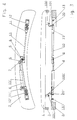
- zeigt in einer schematischen Teilansicht und teilweise im Schnitt das vordere Ende eines mittels einer erfindungsgemäßen Vorrichtung niedergeholten Fahrzeugverdecks, das auf dem einen Teil des Fahrzeugrahmens bildenden Windlauf aufliegt.
Figur 2- zeigt die Vorrichtung aus Figur 1 in einer vereinfachten Ansicht von unten.
Figur 3- zeigt in einer Darstellung entsprechend Figur 1 die Anordnung vor dem Eingriff der Niederholhaken der erfindungsgemäßen Vorrichtung mit den Eingriffselementen des niederzuholenden Fahrzeugverdecks.
Figur 4- zeigt in einer Darstellung entsprechend
Figur 2 den Betriebszustand gemäßFigur 3. Figur 5- zeigt in einer perspektivischen Teildarstellung ein Verschlußteil mit in der Verriegelungsstellung befindlichem Niederholhaken und an diesem angreifendem Ende einer Betätigungsstange gemäß Figuren 1 bis 4.
Figuren 6 bis 12- zeigen in schematischer Darstellung verschiedene Stellungen des Niederholhakens und des Eingriffselementes des Fahrzeugverdecks gemäß Figuren 1 bis 5.
Figuren 13 bis 18- zeigen Darstellungen
entsprechend Figuren 6 bis 12 für eine abgewandelte Niederhol-Vorrichtung.
- Figure 1
- shows in a schematic partial view and partially in section the front end of a vehicle roof brought down by means of a device according to the invention, which lies on the cowl forming part of the vehicle frame.
- Figure 2
- shows the device of Figure 1 in a simplified view from below.
- Figure 3
- shows in a representation corresponding to Figure 1, the arrangement before the engagement of the hold-down hook of the device according to the invention with the engaging elements of the vehicle roof to be pulled down.
- Figure 4
- 2 shows the operating state according to FIG. 3 in a representation corresponding to FIG.
- Figure 5
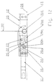
- shows a perspective partial view of a closure part with the hold-down hook located in the locking position and an operating rod according to FIGS. 1 to 4 engaging on this end.
- Figures 6 to 12
- show a schematic representation of various positions of the down hook and the engaging element of the vehicle top according to Figures 1 to 5.
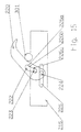
- Figures 13 to 18
- show representations corresponding to Figures 6 to 12 for a modified hold-down device.
Obwohl die Erfindung nachstehend in Zusammenhang mit einem Fahrzeugverdeck beschrieben wird, läßt sie sich auch zum Niederholen einer Haube oder dergleichen, etwa einer Kofferraumhaube oder einer Motorhaube einsetzen.Although the invention is described below in connection with a vehicle roof, it can also be used for pulling down a hood or the like, such as a trunk hood or an engine hood.
In den Figuren 1 bis 4 ist schematisch der oberhalb der Frontscheibe eines Kraftfahrzeugs liegende Windlauf 2 dargestellt, der einen Teil des Fahrzeugrahmens bildet. Oberhalb dieses Windlaufs ist in den Figuren 1 und 3 das vordere Ende eines Fahrzeugverdecks 1 gezeigt, das in nicht dargestellter Weise entweder von Hand oder mittels eines Antriebs aus der Stellung gemäß Figur 3 in eine vollständig zurückgeklappte Stellung und aus dieser in die Stellung gemäß Figur 3 bewegt werden kann. Das Fahrzeugverdeck 1 liegt mit einer an seinem rahmenförmigen Rand vorgesehenen elastischen Dichtung in der verriegelten Stellung gemäß Figur 1 auf dem seitlichen Randbereich des Windlaufes 2 auf.FIGS. 1 to 4 schematically show the
Die Vorrichtung zum Niederholen und Festhalten des vorderen Endes des Fahrzeugverdecks 1 enthält einen als Antrieb dienenden hydraulischen Arbeitszylinder 4, der an der Unterseite des Windlaufes 2 befestigt ist und dessen Kolbenstange mit ihrem freien Ende schwenkbar mit einem Zapfen 7 verbunden ist, der auf einem Gelenkkopf 6 sitzt. Dieser Gelenkkopf ist um eine Mittelachse 5 schwenkbar an einer Grundplatte 8 befestigt, die an der Unterseite des Windlaufes 2 befestigt ist und zu deren beiden Seiten parallel zum Zapfen 7 liegende Zapfen 8, 9 vorgesehen sind. Die Zapfen 8 und 9 stehen in Eingriff mit den freien Enden der inneren Abschnitte 10 und 10' von Betätigungsstangen 10, 11 und 10', 11', von denen jede zur Betätigung eines Niederholhakens 20, 20' dient, die, wie insbesondere den Figuren 1 und 3 zu entnehmen ist, in Eingriff mit an der Unterseite des Fahrzeugverdecks 1 befestigten Eingriffselementen 101, 101' stehen bzw. in Eingriff mit diesen gebracht werden können. Die Eingriffselemente 101, 101' sind jeweils mittels an ihren beiden Enden angreifenden Halteabschnitten 100, 100' an der Unterseite des Fahrzeugverdecks 1 befestigt.The device for pulling down and holding the front end of the vehicle top 1 contains a hydraulic working
Wie sich durch Vergleich der Figuren 1 und 2 und der Figuren 3 und 4 ergibt, lassen sich die Niederholhaken 20, 20' aus ihrer in Figur 3 gezeigten Stellung, in der sie im wesentlichen nach oben gerichtet sind und außer Eingriff mit den Eingriffselementen 101, 101' am Fahrzeugverdeck 1 stehen, durch Betätigung des Arbeitszylinders 4 in die Verriegelungsstellung gemäß Figur 1 bewegen, indem die Kolbenstange des Arbeitszylinders 4 aus der eingefahrenen Stellung gemäß Figur 4 hydraulisch aus dem Zylinder heraus in die Stellung gemäß Figur 2 gefahren wird. Hierdurch wird der Gelenkkopf 6 um die Mittelachse 5 verschwenkt, wodurch die Betätigungsstangen 10, 11 und 10' und 11' so verfahren werden, daß ihre äußeren freien Enden näher zur Mitte des Windlaufes 2 gelangen, also in die Stellung gemäß Figur 2, in der die Niederholhaken 20, 20' in die Verriegelungsstellung abgesenkt sind.As can be seen by comparing FIGS. 1 and 2 and FIGS. 3 and 4, the hold-
Es sei erwähnt, daß die Verlagerung der Betätigungsstangen 10, 11 und 10', 11' selbstverständlich auch mittels anderer Antriebe erfolgen kann, etwa durch getrennte Arbeitszylinder, wie dies in der DE-B-3 923 695 gezeigt ist, oder aber auch von Hand, etwa mittels einer Anordnung gemäß EP-A-0 408 951.It should be mentioned that the
Da die dargestellte Vorrichtung zum Niederholen und Festhalten des vorderen Endes des Fahrzeugverdecks 1 zwei gleichartige, jeweils von einer Betätigungsstange 10, 11 und 10', 11' betätigte, gleich aufgebaute Anordnungen aufweist, wurden die einzelnen Elemente in den beiden Anordnungen mit gleichen Bezugszeichen, jedoch in der linken Anordnung gemäß Figuren 1 bis 4 zusätzlich mit "'" gekennzeichnet. Im folgenden wird wegen dieser Gleichartigkeit im Aufbau nur die in den Figuren 1 bis 4 rechte Anordnung beschrieben werden.Since the illustrated device for pulling down and holding the front end of the vehicle top 1 has two similar arrangements, each of which is actuated by an actuating
Wie insbesondere in Figur 5 dargestellt, ist zur Halterung des Niederholhakens 20 ein Verschlußteil 12 vorhanden, das aus zwei Teilelementen besteht und mit seiner oberen Fläche mittels Schrauben am Windlauf 2 anliegend befestigt wird. Von diesem am Windlauf befestigten Abschnitten des Verschlußteils 12 erstrecken sich Winkelabschnitte 13, 14, 15 nach unten, zwischen denen nicht bezeichnete Distanzelemente mittels Schrauben befestigt sind. Die beiden Elemente des Verschlußteils 12 bilden zwischen sich eine Durchtrittsöffnung 17, in deren Bereich der Niederholhaken 20 angeordnet ist. Der Niederholhaken 20 weist einen länglichen Führschlitz 22 auf, durch den sich ein Führzapfen 23 erstreckt, der am Verschlußteil 12 und somit am Rahmen befestigt ist. Ferner ist im Niederholhaken 20 schwenkbar ein Schwenkzapfen 24 gehaltert, der sich parallel zum Führzapfen 23 und unterhalb von diesem sowie zu beiden Seiten in Aufnahmeschlitze 25 erstreckt, die in den Abschnitten 15 des Verschlußteils 12 ausgebildet sind und deren Funktion später unter Bezugnahme auf einen der Aufnahmeschlitze erläutert wird. Der Schwenkzapfen 24 ist in den Wandungen des gabelkopfförmigen Abschnittes 11 der Betätigungsstange 10, 11 befestigt. Dieser gabelkopfförmige Abschnitt 11 ist in nicht näher dargestellter Weise über eine Schraubverbindung mit dem Abschnitt 10 der Betätigungsstange verbunden.As shown in particular in FIG. 5, there is a
Der Niederholhaken 20 hat eine teilweise gekrümmte Angriffskurve 21, die zum Niederholen des Fahrzeugverdecks 2 in Eingriff mit dem Eingriffselement 101 gebracht wird. Dieses Eingriffselement kann aus einem Rohrteil bestehen, es ist jedoch auch möglich, zur Reibungsverringerung einen Zapfen mit auf ihm drehbar angeordneter Buchse vorzusehen. In diesem Zusammenhang sei erwähnt, daß infolge des Gesamtaufbaus des Fahrzeugverdecks das Eingriffselement 101 nur in einer Senkrechten, d.h. entlang der Linie 102 bewegt werden kann, während seitliche Verlagerungen bezüglich der Linie 102 nicht möglich sind.The pull-
Zur Beschreibung der Funktionsweise der Vorrichtung gemäß Figuren 1 bis 5 wird auf die den Bewegungsablauf beim Niederholen des Fahrzeugverdecks 1 verdeutlichenden Figuren 6 bis 12 Bezug genommen.For a description of the mode of operation of the device according to FIGS. 1 to 5, reference is made to FIGS. 6 to 12, which illustrate the sequence of movements when the vehicle top 1 is lowered.
In der Ausgangsstellung, in der das Fahrzeugverdeck 1 in nicht dargestellter Weise in eine Stellung kurz vor der geschlossenen Stellung gebracht wurde, so daß das Eingriffselement 101 in dem dargestellten Abstand oberhalb der in den Figuren 6 bis 12 jeweils auf gleicher Höhe gezeigten Bezugslinie 103 liegt, befindet sich der Niederholhaken 20 in einer im wesentlichen senkrecht nach oben gerichteten Eingriffsstellung. In diese Stellung wird er durch die Verfahren der Betätigungsstange 10, 11 in den Figuren nach rechts gebracht, und in dieser Stellung liegt der Schwenkzapfen 24 am äußeren, d.h. in den Figuren rechten Ende des Aufnahmeschlitzes 25 und der Führzapfen 23 am oder nahe dem in der Darstellung gemäß Figur 6 unteren Ende des im Niederholhakens 20 ausgebildeten, in seiner Breite an den Durchmesser des Führzapfens 23 angepaßten Führschlitzes 22.In the starting position, in which the vehicle top 1 has been brought into a position shortly before the closed position in a manner not shown, so that the
Der Aufnahmeschlitz 25, dessen Breite so gewählt ist, daß der Schwenkzapfen 24 im wesentlichen von beiden Seitenwänden des Aufnahmeschlitzes geführt gehalten wird, d.h. der Verlauf der Unterkante des Aufnahmeschlitzes 25 entspricht demjenigen seinere Oberkante, ist in etwa in Form eines langgestreckten S gekrümmt. So verläuft der in Figur 6 rechte Abschnitt 26d der unteren Fläche des Aufnahmeschlitzes 25 in etwa horizontal. Nach links schließt an den Abschnitt 26d ein in etwa geradlinig ansteigender Abschnitt 26c an, der an einem den höchsten Punkt des Flächenverlaufs bildenden Zwischenabschnitt 26b endet. Vom Zwischenabschnitt 26b geht dann nach links ein etwas nach unten verlaufender Endabschnitt 26a aus.The receiving
Wird die Betätigungsstange 10, 11 zum Niederholen des Fahrzeugverdecks 1 nach links verlagert, wird dadurch der Schwenkzapfen 24 im Aufnahmeschlitz 25 nach links bewegt, und der Niederholhaken 20 führt eine Schwenkbewegung aus, die um den Führzapfen 23 und unter Verlagerung des Führzapfens 23 bezüglich der Längserstreckung des Führschlitzes 22 stattfindet. Dabei bewegt sich zunächst der Schwenkzapfen 24 entlang dem horizontalen Abschnitt 26d im Aufnahmeschlitz 25, und der Niederholhaken 20 wird in Eingriff mit dem Eingriffselement 101 des Fahrzeugverdecks 1 gebracht (Figur 7). Die weitere Bewegung der Betätigungsstange 10, 11 läßt den Schwenkzapfen 24 entlang dem geradlinig ansteigenden Abschnitt 26c des Aufnahmeschlitzes 25 wandern und bewirkt das Absenken des Eingriffselementes 101 entlang der Linie 102 infolge Schwenkbewegung des in Eingriff mit dem Eingriffselement 101 stehenden Niederholhakens 20 (Figuren 8 und 9). Bei dieser Absenkbewegung nähert sich, wie zu erkennen ist, das Eingriffselement 101 immer mehr der Bezugslinie 103 an.If the actuating
In etwa beginnend mit der Anstiegsbewegung des Schwenkzapfens 24 entlang dem Abschnitt 26c des Aufnahmeschlitzes 25 ergibt sich auch eine Verlagerungsbewegung des Führzapfens 23 entlang dem Führschlitz 22 in Richtung auf das in Figur 9 rechte Ende des Führschlitzes 22. Kurz bevor der Schwenkzapfen 24 den den höchsten Punkt der unteren Fläche des Aufnahmeschlitzes 25 bildenden Zwischenabschnitt 26b erreicht hat, ist das Eingriffselement 101 in eine Lage abgesenkt (Figur 10), die derjenigen entspricht, die es auch in der Verriegelungsstellung einnimmt. Aus dieser Stellung wird das Eingriffselement 101 durch Bewegung des Schwenkzapfens 24 auf den Zwischenbereich 26b des Aufnahmeschlitzes 25 noch weiter entlang der Linie 102 nach unten in eine Stellung bewegt (Figur 11), in der sich der Schwenkzapfen 24 auf dem Zwischenbereich 26b befindet. Diese zusätzliche Absenkung, die durch Vergleich des Abstandes des Eingriffselementes 101 von der Bezugslinie 103 in den Figuren 10 und 11 deutlich wird, bewirkt ein zusätzliches Zusammendrücken der elastischen Dichtung 3 (Figuren 1 und 3), die in Eingriff mit dem Rand des Windlaufs 2 kommt.Approximately starting with the rising movement of the
Die weitere Bewegung der Betätigungsstange 10, 11 nach links verlagert dann den Schwenkzapfen 24 über den Zwischenbereich 26b des Aufnahmeschlitzes 25 hinaus in den etwas tiefer liegenden Endbereich 26a, und infolge der Absenkbewegung des Schwenkzapfens 24 hebt sich der Niederholhaken (20) wieder geringfügig an. Das Eingriffselement 101 des Fahrzeugverdecks 1 befindet sich in der nun erreichten Verriegelungsstellung etwas oberhalb der Bezugslinie 103 und damit wieder in etwa in der Stellung gemäß Figur 10. In dieser Lage hat auch der Führzapfen 23 das rechte Ende des Führschlitzes 22 erreicht. Die Niederholbewegung ist beendet.The further movement of the actuating
In der Verriegelungsstellung gemäß Figur 12 liegt, wie beschrieben, der Schwenkzapfen 24 im gegenüber dem Zwischenabschnitt 26b des Aufnahmeschlitzes 25 tiefer angeordneten Endabschnitt 26a, während die durch elastische Verformung von Dichtungen 3 o.ä. erzeugten Kräfte über das Eingriffselement 101 eine Kraft auf den Niederholhaken 20 ausüben, die in Richtung einer Verdrehung im Gegenuhrzeigersinn (Figur 12) wirkt. Wenn der Niederholhaken aus der Verriegelungsstellung gemäß Figur 12 bewegt werden soll, ist es erforderlich, den Schwenkzapfen 24 über den erhöhten Zwischenabschnitt 26b des Aufnahmeschlitzes 25 zu bewegen, was nur möglich ist, wenn dabei auch das Eingriffselement 101 etwa abgesenkt wird (Figur 11). Das bedeutet aber, daß die im normalen Betrieb auf den in der Verriegelungsstellung befindlichen Niederholhaken 20 wirkenden Kräfte seiner Verlagerung aus der Verriegelungsstellung entgegenwirken, d.h. der Niederholhaken 20 ist selbsthemmend in der Verriegelungsstellung gehalten und kann nur durch Aufbringen einer den wirkenden Kräften entgegengesetzten Kraft gelöst werden, die den Schwenkzapfen 24 über den Zwischenabschnitt 26b des Aufnahmeschlitzes 25 hinausbewegt. Diese lösende Kraft wird zur Freigabe des Fahrzeugverdecks 1 mit Hilfe der Betätigungsstange 10, 11 aufgebracht, die vom Arbeitszylinder 4 in der in Figur 4 angedeuteten Weise nach rechts bewegt wird, wodurch der Schwenkzapfen 24 aus der Stellung gemäß Figur 12 über die Stellung gemäß Figur 11 bewegt und so der Niederholhaken schließlich in die Stellung gemäß Figur 6 verlagert wird.In the locked position according to FIG. 12, as described, the
In dem Ausführungsbeispiel gemäß Figuren 13 bis 18 ist unter Beibehaltung des vorstehend beschriebenen Grundaufbaus eine Abwandlung in der Form von im Verschlußteil vorhandenem Aufnahmeschlitz und von im Niederholhaken vorhandenen Führschlitz vorgenommen. Im übrigen sind in den Figuren 13 bis 18 funktionell gleiche Teile wie in den Figuren 1 bis 12 mit jeweils um 200 erhöhten Bezugszeichen bezeichnet.In the exemplary embodiment according to FIGS. 13 to 18, while maintaining the basic structure described above, a modification is made in the form of the receiving slot provided in the closure part and of the guide slot provided in the hold-down hook. For the rest, parts that are functionally the same in FIGS. 13 to 18 as in FIGS. 1 to 12 are each designated by 200 reference numerals.
Wie zu erkennen ist, ist der im Abschnitt 215 des Verschlußteils vorgesehene Aufnahmeschlitz 225, der den Schwenkzapfen 224 aufnimmt, geradlinig ausgebildet, während der Führzapfen 222 im Niederholhaken 220 eine Kurve bildet. Der Führschlitz 222, dessen in Schlitzlängsrichtung verlaufenden Begrenzungswände im wesentlichen den gleichen Abstand voneinander haben, um den Führzapfen 223 gleitend zu führen, haben an der in Figur 13 nach außen gerichteten und somit dem Eingriffselement 301 des Fahrzeugverdecks zugewandten Seite einen im wesentlichen geradlinigen Abschnitt 226c, mit dem der Führzapfen 223 in der nach oben gerichteten Eingriffsstellung des Niederholhakens 220 in Eingriff steht. Am Ende dieses geradlinigen Abschnitts 226c befindet sich ein Zwischenabschnitt 226b, von dem aus die Seitenwand zu einem bezogen auf den Verlauf des Abschnittes 226c abfallenden Endabschnitt 226a übergeht.As can be seen, the receiving
Wird der Schwenkzapfen 224 durch Verlagerung der in den Figuren 13 bis 18 nicht dargestellten Betätigungsstange im Aufnahmeschlitz 225 nach links bewegt, erfolgt eine Verschwenkbewegung des Niederholhakens 220, durch den dessen Angriffskurve 221 in Eingriff mit dem Eingriffselement 301 des Fahrzeugverdecks kommt und dieses allmählich absenkt (Figuren 14 bis 16). Dabei verlagert sich der Führzapfen 223 entlang dem Abschnitt 226c des Führschlitzes 222 immer mehr in Richtung auf den Zwischenabschnitt 226b. Wenn der Führzapfen 223 den Zwischenabschnitt 226b erreicht hat, ist der Niederholhaken 220 in die am weitesten abgesenkte Stellung verschwenkt, und daher befindet sich auch das Eingriffselement 301 in der bei dem Niederholvorgang auftretenden tiefsten Lage, die der Stellung gemäß Figur 11 im vorstehenden Ausführungsbeispiel entspricht. Bei weiterer Bewegung des Schwenkzapfens 224 im Aufnahmeschlitz 225 nach links bewegt sich der Führzapfen 223 über den Zwischenabschnitt 226b (Figur 17') in den Bereich des Endabschnittes 226a des Führschlitzes 222. Da der Endabschnitt 226a tiefer liegt als der Zwischenabschnitt 226b kann somit der Niederholhaken 220 wieder etwas im Gegenuhrzeigersinn zurückschwenken, und er gelangt in die Verriegelungsstellung gemäß Figur 18.If the
Entsprechend dem Ausührungsbeispiel gemäß Figuren 1 bis 12 wird der Niederholhaken 220 in der Verriegelungsstellung gemäß Figur 18 selbsthemmend gehalten, da der Führzapfen 223 zur Bewegung aus der Verriegelungsstellung über den erhöhten Zwischenabschnitt 226b des Führschlitzes 222 bewegt werden muß, wozu eine Kraft erforderlich ist, die denjenigen Kräften entgegenwirkt, die in der Verriegelungsstellung auf den Niederholhaken 220 wirken.According to the exemplary embodiment according to FIGS. 1 to 12, the hold-
Claims (10)
Priority Applications (5)
| Application Number | Priority Date | Filing Date | Title |
|---|---|---|---|
| EP19900250338 EP0492006B1 (en) | 1990-12-22 | 1990-12-22 | Lowering device of the free edge of vehicle soft top or similar |
| DE59005474T DE59005474D1 (en) | 1990-12-22 | 1990-12-22 | Device for pulling down the free end of a vehicle top or the like. |
| DE19909007595 DE9007595U1 (en) | 1990-12-22 | 1990-12-22 | |
| US07/808,893 US5269586A (en) | 1990-12-22 | 1991-12-18 | Device for lowering the free end of a vehicle cover |
| JP34127191A JPH05213067A (en) | 1990-12-22 | 1991-12-24 | Device for lowering free end of vehicle cover and the like |
Applications Claiming Priority (1)
| Application Number | Priority Date | Filing Date | Title |
|---|---|---|---|
| EP19900250338 EP0492006B1 (en) | 1990-12-22 | 1990-12-22 | Lowering device of the free edge of vehicle soft top or similar |
Publications (2)
| Publication Number | Publication Date |
|---|---|
| EP0492006A1 true EP0492006A1 (en) | 1992-07-01 |
| EP0492006B1 EP0492006B1 (en) | 1994-04-20 |
Family
ID=8205243
Family Applications (1)
| Application Number | Title | Priority Date | Filing Date |
|---|---|---|---|
| EP19900250338 Expired - Lifetime EP0492006B1 (en) | 1990-12-22 | 1990-12-22 | Lowering device of the free edge of vehicle soft top or similar |
Country Status (4)
| Country | Link |
|---|---|
| US (1) | US5269586A (en) |
| EP (1) | EP0492006B1 (en) |
| JP (1) | JPH05213067A (en) |
| DE (2) | DE59005474D1 (en) |
Cited By (20)
| Publication number | Priority date | Publication date | Assignee | Title |
|---|---|---|---|---|
| WO1994011601A1 (en) * | 1992-11-16 | 1994-05-26 | Dura Convertible Systems, Inc. | Self-storing convertible top latch system |
| DE9302292U1 (en) * | 1993-02-17 | 1994-06-16 | Karmann Gmbh W | Locking device for convertible tops |
| WO1996027509A1 (en) * | 1995-03-03 | 1996-09-12 | Mercedes-Benz Aktiengesellschaft | Locking device for detachably securing a vehicle roof to an immovable part of the car body |
| US5595407A (en) * | 1993-12-03 | 1997-01-21 | Jaguar Cars Limited | Roof latching device |
| US5624149A (en) * | 1992-09-04 | 1997-04-29 | Asc Incorporated | Apparatus and method for securing a convertible roof to an automotive vehicle |
| US5755467A (en) * | 1995-01-31 | 1998-05-26 | Asc Incorporated | Latching and switch operating system for a convertible roof |
| EP0850793A1 (en) | 1996-12-30 | 1998-07-01 | Wilhelm Karmann GmbH | Locking device for convertible soft top |
| DE19927236C1 (en) * | 1999-06-15 | 2000-10-12 | Webasto Vehicle Sys Int Gmbh | Locking assembly to secure a sunroof module to an open top automobile has locking hooks to engage counter bolts and a micro-switch signals a control to give the locking action after a dead time |
| DE19927235C1 (en) * | 1999-06-15 | 2000-10-12 | Webasto Vehicle Sys Int Gmbh | Locking system for an automobile roof module has sprung locking hooks which slide to engage counter bolts with a strong and secure holding lock |
| EP1072456A2 (en) * | 1999-07-29 | 2001-01-31 | Lunke Ventra Automotive GmbH | Tensioning and locking device for releasibly fixing a vehicle roof to a vehicle body part |
| EP1112881A2 (en) | 2000-01-01 | 2001-07-04 | Webasto Vehicle Systems International GmbH | Locking device for foldable top |
| DE10124937C1 (en) * | 2001-05-21 | 2002-08-29 | Webasto Vehicle Sys Int Gmbh | Locking device for a folding roof of a vehicle |
| DE10160096C1 (en) * | 2001-12-07 | 2003-04-10 | Webasto Vehicle Sys Int Gmbh | Lock for hood of convertible motor vehicle has hook and receiver catch with bolt moving over last part of closure movement |
| DE10211624A1 (en) * | 2002-03-15 | 2003-10-02 | Webasto Vehicle Sys Int Gmbh | Openable vehicle roof has folding cover and independent auxiliary closing device with interlocking grips |
| DE10139187C2 (en) * | 2001-08-16 | 2003-12-04 | Cts Fahrzeug Dachsysteme Gmbh | Locking device for two relatively adjustable vehicle components |
| DE10242773A1 (en) * | 2002-09-14 | 2004-03-25 | Edscha Cabrio-Dachsysteme Gmbh | Device for joining front of soft top of convertible to frame at windscreen, comprising two sliding elements two be moved in relation to each other |
| WO2006024290A2 (en) * | 2004-09-01 | 2006-03-09 | Wilhelm Karmann Gmbh | Cabriolet |
| WO2007025502A1 (en) * | 2005-09-02 | 2007-03-08 | PARAT Automotive Schönenbach GmbH + Co. KG | Roof construction for motor vehicles |
| US20210285266A1 (en) * | 2020-03-16 | 2021-09-16 | Tectum Holdings, Inc. | Electronic actuated tonneau cover striker assembly |
| WO2022139734A1 (en) * | 2020-12-24 | 2022-06-30 | Yeşi̇lova Holdi̇ng Anoni̇m Şi̇rketi̇ | A ventilation cover mechanism that can be opened with horizontal axis movement |
Families Citing this family (46)
| Publication number | Priority date | Publication date | Assignee | Title |
|---|---|---|---|---|
| US5639129A (en) * | 1995-04-20 | 1997-06-17 | Mcclain Industries Of Oklahoma | Door latch and sealing mechanism for waste containers |
| DE19734671C2 (en) * | 1997-08-11 | 1999-10-21 | Daimler Chrysler Ag | Folding roof arrangement for a motor vehicle with a folding cover |
| US6042174A (en) | 1997-08-22 | 2000-03-28 | Asc Incorporated | Latching and control apparatus for an automotive vehicle convertible roof |
| US5998948A (en) * | 1998-05-29 | 1999-12-07 | Acs Incorporated | Convertible roof actuation mechanism |
| DE19841103C1 (en) | 1998-09-09 | 2000-03-16 | Daimler Chrysler Ag | Hard top road vehicle has front roof part and rear roof part provided with fixed rear plate, lateral main guides for movement of front and rear parts and side vehicle columns |
| US6290281B1 (en) | 1999-05-26 | 2001-09-18 | Asc Incorporated | Power latch for an automotive vehicle convertible roof system |
| DE19960012C1 (en) | 1999-12-13 | 2001-02-15 | Cts Fahrzeug Dachsysteme Gmbh | Arrangement for locking two mutually relatively adjustable, guided elements has locking element blocked from moving towards locking position by control drive when in standby position |
| US6953217B2 (en) * | 2000-06-23 | 2005-10-11 | Cts Fahrzeug - Dachsysteme Gmbh | Locking arrangement for a movable hardtop vehicle roof |
| DE10030760A1 (en) * | 2000-06-23 | 2002-01-10 | Cts Fahrzeug Dachsysteme Gmbh | Locking device for an adjustable vehicle roof |
| USD469336S1 (en) | 2001-06-19 | 2003-01-28 | U-Haul International, Inc. | Keeper |
| USD466391S1 (en) | 2001-06-19 | 2002-12-03 | U-Haul International, Inc. | Handle |
| USD469681S1 (en) | 2001-06-19 | 2003-02-04 | U-Haul International, Inc. | Latch lever |
| CA2354577C (en) | 2001-06-19 | 2007-10-09 | U-Haul International, Inc. | Trailer |
| US7360801B2 (en) | 2001-06-19 | 2008-04-22 | U-Haul International, Inc. | Door latching system |
| USD469335S1 (en) | 2001-06-19 | 2003-01-28 | U-Haul International, Inc. | Striker |
| USD468994S1 (en) | 2001-06-19 | 2003-01-21 | U-Haul International, Inc. | Latch base |
| USD468992S1 (en) | 2001-06-19 | 2003-01-21 | U-Haul International, Inc. | Latch housing |
| USD470744S1 (en) | 2001-06-19 | 2003-02-25 | U-Haul International, Inc. | Rotator clevis |
| USD468993S1 (en) | 2001-06-19 | 2003-01-21 | U-Haul International, Inc. | Hook |
| USD469334S1 (en) | 2001-06-19 | 2003-01-28 | U-Haul International, Inc. | Beak |
| DE10154730A1 (en) * | 2001-11-09 | 2003-05-28 | Cts Fahrzeug Dachsysteme Gmbh | Hard top of the vehicle adjustable between a closed position and an open position |
| IL147691A (en) * | 2002-01-17 | 2006-08-20 | Eyal Artsiely | Rotary motion mechanism |
| DE10205144B4 (en) * | 2002-02-07 | 2005-06-16 | Webasto Ag | Locking device for a folding roof of a vehicle |
| US6758511B2 (en) | 2002-07-31 | 2004-07-06 | Asc Incorporated | Vehicle latch mechanism for convertible tops |
| US6837535B2 (en) | 2002-08-15 | 2005-01-04 | Asc Incorporated | Convertible roof system |
| US6767047B2 (en) | 2002-08-15 | 2004-07-27 | Asc Incorporated | Convertible roof latch |
| US7021696B2 (en) | 2002-11-14 | 2006-04-04 | Asc Incorporated | Convertible top latch |
| DE202004005257U1 (en) * | 2004-04-02 | 2004-05-27 | Wilhelm Karmann Gmbh | Locking device for a convertible top of a convertible motor vehicle |
| FR2873146B1 (en) * | 2004-07-13 | 2007-08-17 | Oxford Automotive Mecanismes E | DEVICE FOR LOCKING AND UNLOCKING A MOBILE ELEMENT OF VEHICLE BODYWORK |
| FR2873145B1 (en) * | 2004-07-13 | 2006-11-03 | Oxford Automotive Mecanismes E | DEVICE FOR LOCKING AND UNLOCKING A MOBILE ELEMENT OF VEHICLE BODYWORK |
| US7438332B2 (en) * | 2004-08-18 | 2008-10-21 | Industrial Technology Research Institute | Cam-action remote latch mechanism |
| US7559585B2 (en) * | 2004-08-20 | 2009-07-14 | Wilhelm Karmann Gmbh | Support frame for header latch assembly |
| DE102004046601A1 (en) * | 2004-09-25 | 2006-04-06 | Wilhelm Karmann Gmbh | Convertible car |
| CN1757520A (en) * | 2004-10-04 | 2006-04-12 | 奥西-技术有限公司 | Ink jet printer |
| DE102005045740B4 (en) * | 2005-09-23 | 2007-12-13 | Magna Car Top Systems Gmbh | Locking between a receiving part and a lid part |
| US7857096B2 (en) * | 2005-10-24 | 2010-12-28 | Werner Co. | Steel pump jack with safety latch and method |
| RU2428323C2 (en) * | 2006-04-21 | 2011-09-10 | Элье | Flap roof lock and vehicle with said lock |
| US20080061564A1 (en) * | 2006-09-12 | 2008-03-13 | Ark-Les Corporation | Vending machine lock system |
| US7976072B2 (en) * | 2007-03-06 | 2011-07-12 | Cooper Technologies Company | Receptacle with rotating release lock |
| US20110175390A1 (en) * | 2010-01-15 | 2011-07-21 | VTI Holdings, Inc. | Retractable Tarp System with Automated Opening/Closing Mechanism |
| CN103687558B (en) * | 2011-05-17 | 2016-05-25 | 捷迈有限公司 | Use the external stability grasping system of trigger mechanism and spring energy-storage |
| US8491032B1 (en) | 2012-07-13 | 2013-07-23 | VTI Holdings, Inc. | Retractable tarp system with automated closing mechanism |
| CN103754267A (en) * | 2013-12-25 | 2014-04-30 | 柳州正菱集团有限公司 | Engine hood lock |
| KR102075935B1 (en) * | 2018-09-19 | 2020-02-11 | 권정수 | Emergency escape device for buildings |
| US11788325B2 (en) * | 2019-09-18 | 2023-10-17 | Kyle Meziere | Method and apparatus for soft close trunk latch retrofit |
| KR102350196B1 (en) * | 2019-11-18 | 2022-01-11 | 재단법인대구경북과학기술원 | Transfer apparatus |
Citations (3)
| Publication number | Priority date | Publication date | Assignee | Title |
|---|---|---|---|---|
| DE190762C (en) * | ||||
| US3831580A (en) * | 1973-11-19 | 1974-08-27 | Corning Glass Works | Lockable oven door latch |
| US4830425A (en) * | 1988-01-04 | 1989-05-16 | Muscat Peter P | Latching system for a convertible top |
Family Cites Families (6)
| Publication number | Priority date | Publication date | Assignee | Title |
|---|---|---|---|---|
| US2703431A (en) * | 1953-01-12 | 1955-03-08 | Jean H Tatom | Latch hinge |
| US3325200A (en) * | 1964-04-06 | 1967-06-13 | Amerock Corp | Latch |
| US3321226A (en) * | 1964-07-23 | 1967-05-23 | Gen Motors Corp | Closure latch |
| USRE27276E (en) * | 1970-03-13 | 1972-01-18 | ||
| US4466644A (en) * | 1982-01-18 | 1984-08-21 | Levan Specialty Co., Inc. | Multi-positioning latch assembly |
| DE3923695C2 (en) * | 1989-07-18 | 1994-02-24 | Karmann Gmbh W | Device for pulling down the front end of a vehicle top |
-
1990
- 1990-12-22 EP EP19900250338 patent/EP0492006B1/en not_active Expired - Lifetime
- 1990-12-22 DE DE59005474T patent/DE59005474D1/en not_active Expired - Lifetime
- 1990-12-22 DE DE19909007595 patent/DE9007595U1/de not_active Expired - Lifetime
-
1991
- 1991-12-18 US US07/808,893 patent/US5269586A/en not_active Expired - Lifetime
- 1991-12-24 JP JP34127191A patent/JPH05213067A/en not_active Withdrawn
Patent Citations (3)
| Publication number | Priority date | Publication date | Assignee | Title |
|---|---|---|---|---|
| DE190762C (en) * | ||||
| US3831580A (en) * | 1973-11-19 | 1974-08-27 | Corning Glass Works | Lockable oven door latch |
| US4830425A (en) * | 1988-01-04 | 1989-05-16 | Muscat Peter P | Latching system for a convertible top |
Cited By (38)
| Publication number | Priority date | Publication date | Assignee | Title |
|---|---|---|---|---|
| US5624149A (en) * | 1992-09-04 | 1997-04-29 | Asc Incorporated | Apparatus and method for securing a convertible roof to an automotive vehicle |
| US5678881A (en) * | 1992-09-04 | 1997-10-21 | Asc Incorporated | Apparatus and method for securing a convertible roof to an automotive vehicle |
| US5772275A (en) * | 1992-09-04 | 1998-06-30 | Asc Incorporated | Apparatus and method for securing a convertible roof to an automobile vehicle |
| WO1994011601A1 (en) * | 1992-11-16 | 1994-05-26 | Dura Convertible Systems, Inc. | Self-storing convertible top latch system |
| DE9302292U1 (en) * | 1993-02-17 | 1994-06-16 | Karmann Gmbh W | Locking device for convertible tops |
| EP0611673A1 (en) * | 1993-02-17 | 1994-08-24 | Wilhelm Karmann GmbH | Locking device for cabriolet-tops |
| US5435615A (en) * | 1993-02-17 | 1995-07-25 | Wilhelm Karmann Gmbh | Locking device for convertible tops |
| US5595407A (en) * | 1993-12-03 | 1997-01-21 | Jaguar Cars Limited | Roof latching device |
| US5755467A (en) * | 1995-01-31 | 1998-05-26 | Asc Incorporated | Latching and switch operating system for a convertible roof |
| WO1996027509A1 (en) * | 1995-03-03 | 1996-09-12 | Mercedes-Benz Aktiengesellschaft | Locking device for detachably securing a vehicle roof to an immovable part of the car body |
| EP0850793A1 (en) | 1996-12-30 | 1998-07-01 | Wilhelm Karmann GmbH | Locking device for convertible soft top |
| DE19927236C1 (en) * | 1999-06-15 | 2000-10-12 | Webasto Vehicle Sys Int Gmbh | Locking assembly to secure a sunroof module to an open top automobile has locking hooks to engage counter bolts and a micro-switch signals a control to give the locking action after a dead time |
| DE19927235C1 (en) * | 1999-06-15 | 2000-10-12 | Webasto Vehicle Sys Int Gmbh | Locking system for an automobile roof module has sprung locking hooks which slide to engage counter bolts with a strong and secure holding lock |
| EP1060925A2 (en) | 1999-06-15 | 2000-12-20 | Webasto Vehicle Systems International GmbH | Locking device |
| EP1060926A2 (en) | 1999-06-15 | 2000-12-20 | Webasto Vehicle Systems International GmbH | Locking device |
| EP1060925A3 (en) * | 1999-06-15 | 2001-10-31 | Webasto Vehicle Systems International GmbH | Locking device |
| EP1072456A2 (en) * | 1999-07-29 | 2001-01-31 | Lunke Ventra Automotive GmbH | Tensioning and locking device for releasibly fixing a vehicle roof to a vehicle body part |
| DE19935738A1 (en) * | 1999-07-29 | 2001-02-15 | Lunke Ventra Automotive Gmbh | Closing and locking device for releasably connecting a vehicle roof to a body component |
| DE19935738C2 (en) * | 1999-07-29 | 2001-05-23 | Lunke Ventra Automotive Gmbh | Closing and locking device for releasably connecting a vehicle roof to a body component |
| EP1072456A3 (en) * | 1999-07-29 | 2002-09-18 | ISE Industries GmbH | Tensioning and locking device for releasibly fixing a vehicle roof to a vehicle body part |
| EP1112881A2 (en) | 2000-01-01 | 2001-07-04 | Webasto Vehicle Systems International GmbH | Locking device for foldable top |
| DE10000002C2 (en) * | 2000-01-01 | 2002-06-27 | Webasto Vehicle Sys Int Gmbh | Locking device for a folding top |
| DE10000002A1 (en) * | 2000-01-01 | 2001-07-12 | Webasto Vehicle Sys Int Gmbh | Locking device for a folding top |
| US6520560B2 (en) | 2000-01-01 | 2003-02-18 | Webasto Vehicle Systems International Gmbh | Latching device for a folding roof |
| DE10124937C1 (en) * | 2001-05-21 | 2002-08-29 | Webasto Vehicle Sys Int Gmbh | Locking device for a folding roof of a vehicle |
| DE10139187C2 (en) * | 2001-08-16 | 2003-12-04 | Cts Fahrzeug Dachsysteme Gmbh | Locking device for two relatively adjustable vehicle components |
| DE10160096C1 (en) * | 2001-12-07 | 2003-04-10 | Webasto Vehicle Sys Int Gmbh | Lock for hood of convertible motor vehicle has hook and receiver catch with bolt moving over last part of closure movement |
| DE10211624A1 (en) * | 2002-03-15 | 2003-10-02 | Webasto Vehicle Sys Int Gmbh | Openable vehicle roof has folding cover and independent auxiliary closing device with interlocking grips |
| DE10242773B4 (en) * | 2002-09-14 | 2004-07-29 | Edscha Cabrio-Dachsysteme Gmbh | Locking device for an openable top |
| DE10242773A1 (en) * | 2002-09-14 | 2004-03-25 | Edscha Cabrio-Dachsysteme Gmbh | Device for joining front of soft top of convertible to frame at windscreen, comprising two sliding elements two be moved in relation to each other |
| US6916061B2 (en) | 2002-09-14 | 2005-07-12 | Edscha Cabrio-Dachsysteme Gmbh | Closure device for a convertible top |
| DE10242773C5 (en) * | 2002-09-14 | 2014-10-09 | Webasto Ag | Closing device for an openable hood |
| WO2006024290A2 (en) * | 2004-09-01 | 2006-03-09 | Wilhelm Karmann Gmbh | Cabriolet |
| WO2006024290A3 (en) * | 2004-09-01 | 2006-06-01 | Karmann Gmbh W | Cabriolet |
| WO2007025502A1 (en) * | 2005-09-02 | 2007-03-08 | PARAT Automotive Schönenbach GmbH + Co. KG | Roof construction for motor vehicles |
| US20210285266A1 (en) * | 2020-03-16 | 2021-09-16 | Tectum Holdings, Inc. | Electronic actuated tonneau cover striker assembly |
| US11725433B2 (en) * | 2020-03-16 | 2023-08-15 | Extang Corporation | Electronic actuated tonneau cover striker assembly |
| WO2022139734A1 (en) * | 2020-12-24 | 2022-06-30 | Yeşi̇lova Holdi̇ng Anoni̇m Şi̇rketi̇ | A ventilation cover mechanism that can be opened with horizontal axis movement |
Also Published As
| Publication number | Publication date |
|---|---|
| EP0492006B1 (en) | 1994-04-20 |
| DE59005474D1 (en) | 1994-06-01 |
| DE9007595U1 (en) | 1993-03-04 |
| US5269586A (en) | 1993-12-14 |
| JPH05213067A (en) | 1993-08-24 |
Similar Documents
| Publication | Publication Date | Title |
|---|---|---|
| EP0492006B1 (en) | Lowering device of the free edge of vehicle soft top or similar | |
| EP2451665B2 (en) | Sliding roof device, in particular for a motor vehicle | |
| DE19846307C2 (en) | Ventilation device | |
| EP0017765B1 (en) | Hydraulic lifting device | |
| DE2450909A1 (en) | REMOTE CONTROL DEVICE FOR OPENING AND CLOSING A VEHICLE DOOR | |
| EP1561620A2 (en) | Mechanism for a sliding roof | |
| DE102007007997B3 (en) | Drawing device for e.g. rotary tilting wing, has drawing arm displaced in end region by guiding device in retracted condition such that arm displaces with side in direction of base part in region of connecting link arrangement | |
| DE202008018448U1 (en) | Parallel adjustable fitting for a sliding sash of a window or door | |
| EP1577136A2 (en) | Sliding roof arrangement | |
| DE69928601T2 (en) | Device for adjusting a sunroof cover of a motor vehicle | |
| EP0119433B2 (en) | Fitting for a wing of a window, door or the like, which is at least tiltable and movable from one plane to a second parallel plane | |
| EP3405359B1 (en) | Open roof construction with panel for a vehicle | |
| DE3522781A1 (en) | SLIDING ROOF FOR VEHICLES | |
| EP0178610A2 (en) | Lock | |
| DE102011085177B4 (en) | Drive system for a motor vehicle roof system | |
| DE102018130016A1 (en) | Sunroof system for a motor vehicle | |
| DE2926113C2 (en) | Locking device for lift-slide-tilt doors or windows | |
| EP2463467A2 (en) | Narrow three-position actuating device for controlling a parallel movement of a door- or window-wing | |
| DE3922874C2 (en) | ||
| DE3334298C2 (en) | ||
| DE4304155A1 (en) | Automatic floor seal for a door | |
| DE19509590C1 (en) | Stanchion that is slidably adjustable in height | |
| CH628390A5 (en) | Vertical sash window | |
| EP1561891A2 (en) | Swinging mechanism for opening and closing a door with a door leaf and a door frame, especially for a vehicle door | |
| EP0167767A2 (en) | Locking device having at least one bolt, and a dogging device |
Legal Events
| Date | Code | Title | Description |
|---|---|---|---|
| PUAI | Public reference made under article 153(3) epc to a published international application that has entered the european phase |
Free format text: ORIGINAL CODE: 0009012 |
|
| AK | Designated contracting states |
Kind code of ref document: A1 Designated state(s): DE FR GB IT |
|
| 17P | Request for examination filed |
Effective date: 19921228 |
|
| 17Q | First examination report despatched |
Effective date: 19930813 |
|
| GRAA | (expected) grant |
Free format text: ORIGINAL CODE: 0009210 |
|
| AK | Designated contracting states |
Kind code of ref document: B1 Designated state(s): DE FR GB IT |
|
| ITF | It: translation for a ep patent filed |
Owner name: ING. A. GIAMBROCONO & C. S.R.L. |
|
| REF | Corresponds to: |
Ref document number: 59005474 Country of ref document: DE Date of ref document: 19940601 |
|
| GBT | Gb: translation of ep patent filed (gb section 77(6)(a)/1977) |
Effective date: 19940510 |
|
| ET | Fr: translation filed | ||
| PLBE | No opposition filed within time limit |
Free format text: ORIGINAL CODE: 0009261 |
|
| STAA | Information on the status of an ep patent application or granted ep patent |
Free format text: STATUS: NO OPPOSITION FILED WITHIN TIME LIMIT |
|
| 26N | No opposition filed | ||
| REG | Reference to a national code |
Ref country code: FR Ref legal event code: TP |
|
| REG | Reference to a national code |
Ref country code: GB Ref legal event code: 732E |
|
| PGFP | Annual fee paid to national office [announced via postgrant information from national office to epo] |
Ref country code: FR Payment date: 20011214 Year of fee payment: 12 |
|
| REG | Reference to a national code |
Ref country code: GB Ref legal event code: IF02 |
|
| PGFP | Annual fee paid to national office [announced via postgrant information from national office to epo] |
Ref country code: GB Payment date: 20021210 Year of fee payment: 13 |
|
| PG25 | Lapsed in a contracting state [announced via postgrant information from national office to epo] |
Ref country code: FR Free format text: LAPSE BECAUSE OF NON-PAYMENT OF DUE FEES Effective date: 20030901 |
|
| REG | Reference to a national code |
Ref country code: FR Ref legal event code: ST |
|
| PG25 | Lapsed in a contracting state [announced via postgrant information from national office to epo] |
Ref country code: GB Free format text: LAPSE BECAUSE OF NON-PAYMENT OF DUE FEES Effective date: 20031222 |
|
| GBPC | Gb: european patent ceased through non-payment of renewal fee |
Effective date: 20031222 |
|
| PG25 | Lapsed in a contracting state [announced via postgrant information from national office to epo] |
Ref country code: IT Free format text: LAPSE BECAUSE OF NON-PAYMENT OF DUE FEES;WARNING: LAPSES OF ITALIAN PATENTS WITH EFFECTIVE DATE BEFORE 2007 MAY HAVE OCCURRED AT ANY TIME BEFORE 2007. THE CORRECT EFFECTIVE DATE MAY BE DIFFERENT FROM THE ONE RECORDED. Effective date: 20051222 |
|
| PGFP | Annual fee paid to national office [announced via postgrant information from national office to epo] |
Ref country code: DE Payment date: 20091228 Year of fee payment: 20 |
|
| PG25 | Lapsed in a contracting state [announced via postgrant information from national office to epo] |
Ref country code: DE Free format text: LAPSE BECAUSE OF EXPIRATION OF PROTECTION Effective date: 20101222 |