EP0490504A2 - Multilevel line coding scheme - Google Patents
Multilevel line coding scheme Download PDFInfo
- Publication number
- EP0490504A2 EP0490504A2 EP91310712A EP91310712A EP0490504A2 EP 0490504 A2 EP0490504 A2 EP 0490504A2 EP 91310712 A EP91310712 A EP 91310712A EP 91310712 A EP91310712 A EP 91310712A EP 0490504 A2 EP0490504 A2 EP 0490504A2
- Authority
- EP
- European Patent Office
- Prior art keywords
- level
- binary
- word
- penternary
- code
- Prior art date
- Legal status (The legal status is an assumption and is not a legal conclusion. Google has not performed a legal analysis and makes no representation as to the accuracy of the status listed.)
- Withdrawn
Links
Images

Classifications
-
- H—ELECTRICITY
- H04—ELECTRIC COMMUNICATION TECHNIQUE
- H04L—TRANSMISSION OF DIGITAL INFORMATION, e.g. TELEGRAPHIC COMMUNICATION
- H04L25/00—Baseband systems
- H04L25/38—Synchronous or start-stop systems, e.g. for Baudot code
- H04L25/40—Transmitting circuits; Receiving circuits
- H04L25/49—Transmitting circuits; Receiving circuits using code conversion at the transmitter; using predistortion; using insertion of idle bits for obtaining a desired frequency spectrum; using three or more amplitude levels ; Baseband coding techniques specific to data transmission systems
- H04L25/4917—Transmitting circuits; Receiving circuits using code conversion at the transmitter; using predistortion; using insertion of idle bits for obtaining a desired frequency spectrum; using three or more amplitude levels ; Baseband coding techniques specific to data transmission systems using multilevel codes
- H04L25/4919—Transmitting circuits; Receiving circuits using code conversion at the transmitter; using predistortion; using insertion of idle bits for obtaining a desired frequency spectrum; using three or more amplitude levels ; Baseband coding techniques specific to data transmission systems using multilevel codes using balanced multilevel codes
Definitions
- This invention relates to a data transmission system in which the data to be transmitted is expressed in a binary code which is converted into a multilevel line code before transmission.
- a digital data transmission system including a transmission equipment comprising means for sampling an input set of binary encoded digital data bits, means for converting the sampled binary encoded set into a selected five-level (penternary or quinternary) line code word for transmission over the system, characterised in that the system further includes means for storing each penternary word output from the converting means for a predetermined period of time and means for controlling the selection of a succeeding penternary word conditional on the value of the stored penternary word.
- the binary to five-level conversion is of the 2B1 P type, wherein each successive group of two binary coded bits is converted into a single five-level bit, the equivalent five-level line code employing a predetermined one of all the five level states.
- the binary conversion is of the 9B4P type wherein each successive group of nine binary coded bits is converted into a group of four five-level bits, the equivalent five-level line code employing a predetermined one of all of the combinations of four out of five five-level states.
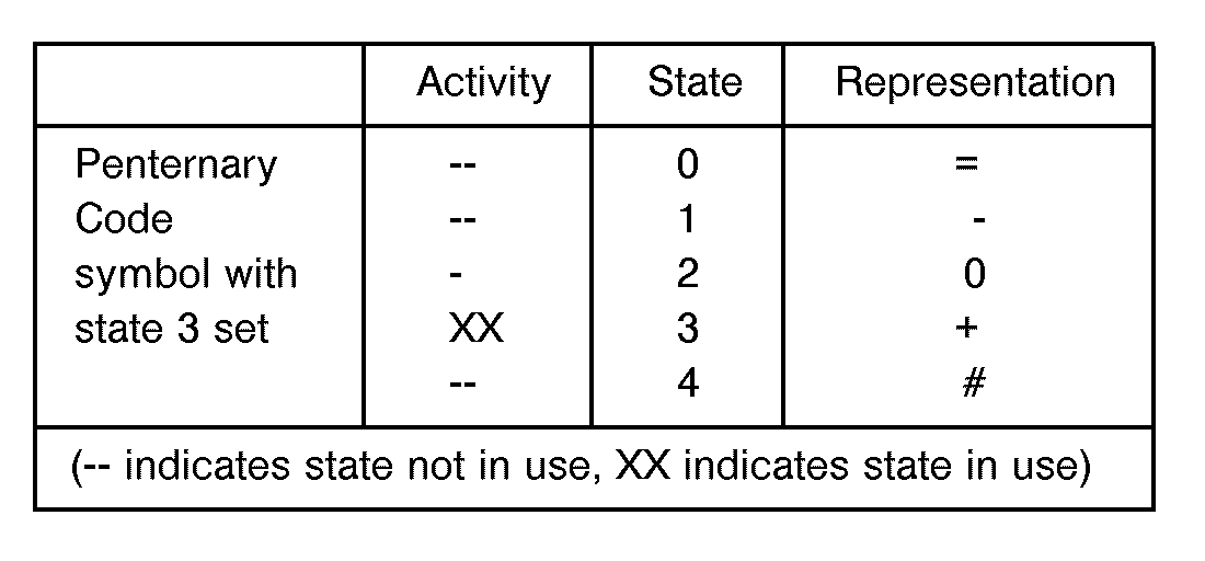
- Code variant 2B1 P is a penternary line code in which successive sets of two binary elements are coded into one penternary element, wherein the penternary code employs all of the following five penternary elements: For example:
- Code variant 9B4P is a penternary line code in which successive sets of nine binary elements are coded into successive sets of four penternary elements, wherein the penternary line code employs all of the six hundred and twenty-five sets of four penternary elements, an example sub-set of which is given below:
- Each code variant employs conditional code word selection whereby the current set of penternary elements or the current penternary code word to be transmitted is dependent on previously transmitted code words.
- the line code and its variants herein described are suitable for use in a variety of applications, and particularly for the transmission over twisted wire cables at data rates in the region of 448 Kbit/s.
- the line code is also suited to data transmission rate from circa 144 Kbit/s to the order of 3 Mbit/s.
- the coder produces a series of symbols containing five discrete states referred to as a penternary (or quinternary) line code.
- the code symbol may have one or none of five values or states.
- the value or state set/selected is dependent on the data being coded and/or dependent on any number of previous code symbols.
- the data to be coded may be in any number base or format.
- This variant of the coder is a state machine which encodes two binary bits as one penternary symbol or code word.
- One of the four states represented by the two-bit binary word is mapped into one of the five states of the penternary code.
- the exact mapping is not fixed (conditional) and may be varied to use any of the five levels in order to adapt the energy spectrum of the transmitted penternary encoded data according to requirements.
- the mapping can be made to be dependent on previously transmitted code words thus making the most efficient use of network transmission bandwidth.
- the unused penternary state resulting from the mapping can be used for overhead, synchronisation and management control or transmission of extra data.
- the 2B1 P coder 10 samples the two-bit binary word comprising B1 (t) and B2(t) at sample time 't'.
- the coder uses a look-up table 12 or code word decision algorithm to select the penternary symbol to be transmitted, P(t).
- the selected penternary symbol is transmitted and also stored in a penternary shift register 14 of length 'n' time samples. This new stored symbol P(t) is then used 'n' time samples later to process B1 (t + n) to select symbol P(t + n).
- Example mapping table for binary data with a unit delay shift register Example mapping table for binary data with a unit delay shift register.
- This variant of the code encodes nine binary bits into a four penternary-symbol word.
- the binary to penternary coder 20 samples the 9-bit binary word comprising bits BO(t)-B8(t) at sample time 't'.
- the coder accesses look-up table 22 to select the 4-bit penternary code group (PO(t)-P3(t) to be transmitted.
- the selected group PO(t)-P3(t) is transmitted and also stored in penternary 4- symbol parallel shift register 24.
- the shift register has a length equal to n words.
- the newly stored group PO(t)-P3(t) is then used 'n' time samples later to process the binary group BO(t+n)-B8(t+n) to select penternary group PO(t + n)-P3(t + n).
- the data compression ratio is greater than that for 2B1 P.
- Conditional selection of a subset of the 625 penternary words is made and only words which have the required spectral content are used for data encoding. The remaining words can be used for system overhead and synchronisation or data transmission.
- the code word selection mechanism conditionally selects the code word depending on the frequency content of the current four symbol penternary code word and previously transmitted words. The selection process may be varied to make optimum use of the network bandwidth.
Abstract
Description
- This invention relates to a data transmission system in which the data to be transmitted is expressed in a binary code which is converted into a multilevel line code before transmission.
- One example of such a multilevel code is the code described in our Patent No. 1156279, where the code is of the 4B3T type, which means that successive groups each of four binary bits are converted for transmission into groups of three ternary elements. Another example is the equally well-known 3B2T line code.
- According to the present invention there is provided a digital data transmission system including a transmission equipment comprising means for sampling an input set of binary encoded digital data bits, means for converting the sampled binary encoded set into a selected five-level (penternary or quinternary) line code word for transmission over the system, characterised in that the system further includes means for storing each penternary word output from the converting means for a predetermined period of time and means for controlling the selection of a succeeding penternary word conditional on the value of the stored penternary word.
- In a first embodiment of the invention the binary to five-level conversion is of the 2B1 P type, wherein each successive group of two binary coded bits is converted into a single five-level bit, the equivalent five-level line code employing a predetermined one of all the five level states.
- In a second embodiment of the invention the binary conversion is of the 9B4P type wherein each successive group of nine binary coded bits is converted into a group of four five-level bits, the equivalent five-level line code employing a predetermined one of all of the combinations of four out of five five-level states.
- Embodiments of the invention are described with reference to the accompanying drawings, in which:
- Fig. 1 illustrates an example of implementation of a 2B1 P binary to penternary coder, and
- Fig. 2 illustrates an example of implementation of a 9B4P binary to penternary coder.
- Code variant 2B1 P is a penternary line code in which successive sets of two binary elements are coded into one penternary element, wherein the penternary code employs all of the following five penternary elements:

- Code variant 9B4P is a penternary line code in which successive sets of nine binary elements are coded into successive sets of four penternary elements, wherein the penternary line code employs all of the six hundred and twenty-five sets of four penternary elements, an example sub-set of which is given below:Each code variant employs conditional code word selection whereby the current set of penternary elements or the current penternary code word to be transmitted is dependent on previously transmitted code words.

- The line code and its variants herein described are suitable for use in a variety of applications, and particularly for the transmission over twisted wire cables at data rates in the region of 448 Kbit/s. The line code is also suited to data transmission rate from circa 144 Kbit/s to the order of 3 Mbit/s.
- The coder produces a series of symbols containing five discrete states referred to as a penternary (or quinternary) line code.
- At any instant the code symbol may have one or none of five values or states. The value or state set/selected is dependent on the data being coded and/or dependent on any number of previous code symbols. The data to be coded may be in any number base or format.
- Specific variants of the coding scheme
- 2B1 P - Two binary bits encoded as one penternary/quinternary/five-level code symbol, with and without conditional code word selection.
- This variant of the coder is a state machine which encodes two binary bits as one penternary symbol or code word. One of the four states represented by the two-bit binary word is mapped into one of the five states of the penternary code. The exact mapping is not fixed (conditional) and may be varied to use any of the five levels in order to adapt the energy spectrum of the transmitted penternary encoded data according to requirements. The mapping can be made to be dependent on previously transmitted code words thus making the most efficient use of network transmission bandwidth. The unused penternary state resulting from the mapping can be used for overhead, synchronisation and management control or transmission of extra data.
- With reference to Figure 1, the
2B1 P coder 10 samples the two-bit binary word comprising B1 (t) and B2(t) at sample time 't'. The coder uses a look-up table 12 or code word decision algorithm to select the penternary symbol to be transmitted, P(t). P(t) is dependent on P(t-n), which is the previously transmitted penternary symbol for the case where n = 1. The selected penternary symbol is transmitted and also stored in apenternary shift register 14 of length 'n' time samples. This new stored symbol P(t) is then used 'n' time samples later to process B1 (t + n) to select symbol P(t + n). - Example mapping table for binary data with a unit delay shift register.

- This variant of the code encodes nine binary bits into a four penternary-symbol word. With reference to Fig. 2 the binary to
penternary coder 20 samples the 9-bit binary word comprising bits BO(t)-B8(t) at sample time 't'. The coder accesses look-up table 22 to select the 4-bit penternary code group (PO(t)-P3(t) to be transmitted. PO(t)-P3(t) is dependent on a preceding group PO(t-n)-P3(t-n), which is the immediately preceding group when n = 1. The selected group PO(t)-P3(t) is transmitted and also stored in penternary 4- symbolparallel shift register 24. The shift register has a length equal to n words. The newly stored group PO(t)-P3(t) is then used 'n' time samples later to process the binary group BO(t+n)-B8(t+n) to select penternary group PO(t + n)-P3(t + n). The data compression ratio is greater than that for 2B1 P. Conditional selection of a subset of the 625 penternary words is made and only words which have the required spectral content are used for data encoding. The remaining words can be used for system overhead and synchronisation or data transmission. The code word selection mechanism conditionally selects the code word depending on the frequency content of the current four symbol penternary code word and previously transmitted words. The selection process may be varied to make optimum use of the network bandwidth. - Example of 9B4P mapping.

Claims (7)
Applications Claiming Priority (2)
| Application Number | Priority Date | Filing Date | Title |
|---|---|---|---|
| GB9026996A GB2250898A (en) | 1990-12-12 | 1990-12-12 | Line coding scheme. |
| GB9026996 | 1990-12-12 |
Publications (2)
| Publication Number | Publication Date |
|---|---|
| EP0490504A2 true EP0490504A2 (en) | 1992-06-17 |
| EP0490504A3 EP0490504A3 (en) | 1993-05-26 |
Family
ID=10686903
Family Applications (1)
| Application Number | Title | Priority Date | Filing Date |
|---|---|---|---|
| EP19910310712 Withdrawn EP0490504A3 (en) | 1990-12-12 | 1991-11-20 | Multilevel line coding scheme |
Country Status (3)
| Country | Link |
|---|---|
| US (1) | US5191330A (en) |
| EP (1) | EP0490504A3 (en) |
| GB (1) | GB2250898A (en) |
Cited By (12)
| Publication number | Priority date | Publication date | Assignee | Title |
|---|---|---|---|---|
| WO1996036122A1 (en) * | 1995-05-12 | 1996-11-14 | Optex Corporation | M-ary (d,k) RUNLENGTH LIMITED CODING FOR MULTI-LEVEL DATA |
| US5903231A (en) * | 1996-12-16 | 1999-05-11 | Vidicast Ltd. | System for encoding base N data using a multi-level coding scheme |
| EP0949785A2 (en) * | 1998-04-07 | 1999-10-13 | Matsushita Electric Industrial Co., Ltd. | Method and device for transmitting a DC balanced multilevel code |
| US6122010A (en) * | 1996-12-16 | 2000-09-19 | Vidicast Ltd. | Television signal data transmission system |
| US6359931B1 (en) | 1996-12-20 | 2002-03-19 | Rambus Inc. | Apparatus and method for multilevel signaling |
| EP1330083A1 (en) * | 2000-10-05 | 2003-07-23 | Matsushita Electric Industrial Co., Ltd. | Digital data transmitter |
| EP1331776A1 (en) * | 2000-10-05 | 2003-07-30 | Matsushita Electric Industrial Co., Ltd. | Digital data transmitter, transmission line encoding method, and decoding method |
| US7012936B2 (en) | 2000-10-05 | 2006-03-14 | Matsushita Electric Industrial Co., Ltd. | Initializing method and data transmitter |
| US7133936B2 (en) | 2000-10-05 | 2006-11-07 | Matsushita Electric Industrial Co., Ltd. | Ring network and data transmitter |
| US7292629B2 (en) | 2002-07-12 | 2007-11-06 | Rambus Inc. | Selectable-tap equalizer |
| US7809088B2 (en) | 1999-10-19 | 2010-10-05 | Rambus Inc. | Multiphase receiver with equalization |
| US8861667B1 (en) | 2002-07-12 | 2014-10-14 | Rambus Inc. | Clock data recovery circuit with equalizer clock calibration |
Families Citing this family (8)
| Publication number | Priority date | Publication date | Assignee | Title |
|---|---|---|---|---|
| US5794685A (en) * | 1996-12-17 | 1998-08-18 | Hewlett-Packard Company | Heat sink device having radial heat and airflow paths |
| US6396329B1 (en) | 1999-10-19 | 2002-05-28 | Rambus, Inc | Method and apparatus for receiving high speed signals with low latency |
| US7269212B1 (en) | 2000-09-05 | 2007-09-11 | Rambus Inc. | Low-latency equalization in multi-level, multi-line communication systems |
| US7161513B2 (en) * | 1999-10-19 | 2007-01-09 | Rambus Inc. | Apparatus and method for improving resolution of a current mode driver |
| US6763477B1 (en) * | 2000-07-31 | 2004-07-13 | Hewlett-Packard Development Company, L.P. | Method and apparatus for transmitting and receiving data using a self clocking link protocol |
| US7362800B1 (en) | 2002-07-12 | 2008-04-22 | Rambus Inc. | Auto-configured equalizer |
| US6956510B1 (en) * | 2004-05-14 | 2005-10-18 | Marvell International Ltd. | Methods, software, circuits and systems for coding information |
| US7787526B2 (en) * | 2005-07-12 | 2010-08-31 | Mcgee James Ridenour | Circuits and methods for a multi-differential embedded-clock channel |
Citations (1)
| Publication number | Priority date | Publication date | Assignee | Title |
|---|---|---|---|---|
| US3832490A (en) * | 1972-10-13 | 1974-08-27 | Co Ind Des Communication Cit A | Coder for increase of transmission speed |
Family Cites Families (4)
| Publication number | Priority date | Publication date | Assignee | Title |
|---|---|---|---|---|
| US3337863A (en) * | 1964-01-17 | 1967-08-22 | Automatic Elect Lab | Polybinary techniques |
| GB1250493A (en) * | 1967-07-27 | 1971-10-20 | ||
| BE789644A (en) * | 1971-10-13 | 1973-04-04 | Cit Alcatel | ENCODER AT INCREASED TRANSMISSION SPEED |
| JPH0681164B2 (en) * | 1984-02-01 | 1994-10-12 | 株式会社日立製作所 | Code modulation method |
-
1990
- 1990-12-12 GB GB9026996A patent/GB2250898A/en not_active Withdrawn
-
1991
- 1991-11-20 EP EP19910310712 patent/EP0490504A3/en not_active Withdrawn
- 1991-12-12 US US07/806,723 patent/US5191330A/en not_active Expired - Fee Related
Patent Citations (1)
| Publication number | Priority date | Publication date | Assignee | Title |
|---|---|---|---|---|
| US3832490A (en) * | 1972-10-13 | 1974-08-27 | Co Ind Des Communication Cit A | Coder for increase of transmission speed |
Non-Patent Citations (4)
| Title |
|---|
| GLOBECOMM '90, IEEE GLOBAL TELECOMMUNICATIONS CONFERENCE & EXHIBITION vol. 2, 5 December 1990, SAN DIEGO, CALIFORNIA pages 714 - 719 L. BOTHA ET AL 'NEW MULTILEVEL LINE CODES' * |
| IEE PROCEEDINGS SECTION A à I vol. 132, no. 6, 3 October 1985, GUILFORD,SURREY,GREAT BRITAIN pages 441 - 446 J.J. O'REILLY ET AL 'LINE CODE DESIGN FOR DIGITAL PULSE-POSITION MODULATION' * |
| IEEE INTERNATIONAL SYMPOSIUM ON CIRCUITS AND SYSTEMS vol. 1, 9 June 1988, ESPOO, FINLAND pages 861 - 864 P.F. ADAMS,R.P. COLBECK 'CONSIDERATIONS IN THE VLSI IMPLEMENTATIONS OF 2B1Q TRANSCEIVERS' * |
| TELECOMMUNICATIONS AND RADIO ENGINEERING, AUGUST 1986 vol. 40/41, no. 8, WASHINGTON US pages 19 - 24 D.G. TUNEV 'A MULTILEVEL CODE FOR DIGITAL TRANSMISSION SYSTEMS' * |
Cited By (27)
| Publication number | Priority date | Publication date | Assignee | Title |
|---|---|---|---|---|
| WO1996036122A1 (en) * | 1995-05-12 | 1996-11-14 | Optex Corporation | M-ary (d,k) RUNLENGTH LIMITED CODING FOR MULTI-LEVEL DATA |
| US6122010A (en) * | 1996-12-16 | 2000-09-19 | Vidicast Ltd. | Television signal data transmission system |
| US5903231A (en) * | 1996-12-16 | 1999-05-11 | Vidicast Ltd. | System for encoding base N data using a multi-level coding scheme |
| US6504875B2 (en) | 1996-12-20 | 2003-01-07 | Rambus Inc. | Apparatus for multilevel signaling |
| US6359931B1 (en) | 1996-12-20 | 2002-03-19 | Rambus Inc. | Apparatus and method for multilevel signaling |
| EP0949785A3 (en) * | 1998-04-07 | 2001-10-31 | Matsushita Electric Industrial Co., Ltd. | Method and device for transmitting a DC balanced multilevel code |
| US6577684B1 (en) | 1998-04-07 | 2003-06-10 | Matsushita Electric Industrial Co., Ltd. | Transmission/reception method and device where information is encoded and decoded according to rules defined based on a relation between a previously-generated multilevel code and a currently generated multilevel |
| EP0949785A2 (en) * | 1998-04-07 | 1999-10-13 | Matsushita Electric Industrial Co., Ltd. | Method and device for transmitting a DC balanced multilevel code |
| KR100602309B1 (en) * | 1998-04-07 | 2006-07-14 | 마쯔시다덴기산교 가부시키가이샤 | Transmission method and transmission device |
| US7809088B2 (en) | 1999-10-19 | 2010-10-05 | Rambus Inc. | Multiphase receiver with equalization |
| US9998305B2 (en) | 1999-10-19 | 2018-06-12 | Rambus Inc. | Multi-PAM output driver with distortion compensation |
| US9544169B2 (en) | 1999-10-19 | 2017-01-10 | Rambus Inc. | Multiphase receiver with equalization circuitry |
| US8634452B2 (en) | 1999-10-19 | 2014-01-21 | Rambus Inc. | Multiphase receiver with equalization circuitry |
| US8199859B2 (en) | 1999-10-19 | 2012-06-12 | Rambus Inc. | Integrating receiver with precharge circuitry |
| US7859436B2 (en) | 1999-10-19 | 2010-12-28 | Rambus Inc. | Memory device receiver |
| US7012936B2 (en) | 2000-10-05 | 2006-03-14 | Matsushita Electric Industrial Co., Ltd. | Initializing method and data transmitter |
| US7190728B2 (en) | 2000-10-05 | 2007-03-13 | Matsushita Electric Industrial Co., Ltd. | Digital data transmitter, transmission line encoding method, and decoding method |
| US7218678B2 (en) | 2000-10-05 | 2007-05-15 | Matsushita Electric Industrial Co., Ltd. | Digital data transmitter |
| EP1933512A1 (en) * | 2000-10-05 | 2008-06-18 | Matsushita Electric Industrial Co., Ltd. | Digital data transmission apparatus as well as transmission channel coding method and decoding method |
| US7133936B2 (en) | 2000-10-05 | 2006-11-07 | Matsushita Electric Industrial Co., Ltd. | Ring network and data transmitter |
| US7042965B2 (en) | 2000-10-05 | 2006-05-09 | Matsushita Electric Industrial Co., Ltd. | Judgment level setting method and data receiver |
| EP1330083A4 (en) * | 2000-10-05 | 2004-07-14 | Matsushita Electric Ind Co Ltd | Digital data transmitter |
| EP1331776A4 (en) * | 2000-10-05 | 2004-07-14 | Matsushita Electric Ind Co Ltd | Digital data transmitter, transmission line encoding method, and decoding method |
| EP1331776A1 (en) * | 2000-10-05 | 2003-07-30 | Matsushita Electric Industrial Co., Ltd. | Digital data transmitter, transmission line encoding method, and decoding method |
| EP1330083A1 (en) * | 2000-10-05 | 2003-07-23 | Matsushita Electric Industrial Co., Ltd. | Digital data transmitter |
| US7292629B2 (en) | 2002-07-12 | 2007-11-06 | Rambus Inc. | Selectable-tap equalizer |
| US8861667B1 (en) | 2002-07-12 | 2014-10-14 | Rambus Inc. | Clock data recovery circuit with equalizer clock calibration |
Also Published As
| Publication number | Publication date |
|---|---|
| EP0490504A3 (en) | 1993-05-26 |
| US5191330A (en) | 1993-03-02 |
| GB9026996D0 (en) | 1991-01-30 |
| GB2250898A (en) | 1992-06-17 |
Similar Documents
| Publication | Publication Date | Title |
|---|---|---|
| EP0490504A2 (en) | Multilevel line coding scheme | |
| EP0824817B1 (en) | Apparatus and method for communicating data word blocks together with control words | |
| CA1244948A (en) | Data communication with modified huffman coding | |
| EP0098153B1 (en) | Digital data code conversion circuit for variable-word-length data code | |
| US4586182A (en) | Source coded modulation system | |
| US5280503A (en) | Data communication system with data rate throttling | |
| KR860002214B1 (en) | Successive frame digital multiplexer with increased channel capacity | |
| EP0227473A2 (en) | Error correcting coder/decoder | |
| Croisier | Introduction to pseudoternary transmission codes | |
| WO1998038752A1 (en) | Mapper for high data rate signalling | |
| US5694128A (en) | Tree structured binary arithmetic coder | |
| KR0167092B1 (en) | Encoding method and apparatus for digital data statistically | |
| EP0406507A1 (en) | Block coding scheme for fractional-bit transmission | |
| US4825451A (en) | Technique for transmission of voice communications and apparatus useful therein | |
| US5021782A (en) | Variable length encoding method and variable length decoding method, encoding device and decoridng device for the implementation of this method | |
| US4092595A (en) | Data transmission system for transmitting primary and secondary intelligence | |
| Biglieri | Ungerboeck codes do not shape the signal power spectrum (Corresp.) | |
| CA1189974A (en) | Code conversion system | |
| AU671655B2 (en) | A method of distinguishing in serial digital bit streams between at least two types of time slots in a bit stream receiver | |
| JP3960629B2 (en) | Transmission system using variable length encoder | |
| EP0880838A1 (en) | Method of communicating according to a trellis code chosen from a fixed set of baseband signal points | |
| DE2517848A1 (en) | DIGITAL CHARACTERISTICS IN A PULSE CODE MODULATION TRANSMISSION SYSTEM | |
| EP0166607B1 (en) | Encoding method for time encoded data | |
| EP0193592B1 (en) | Method and apparatus for processing digital signals prior to recording | |
| US5034741A (en) | Variable length bit patterns for data representation |
Legal Events
| Date | Code | Title | Description |
|---|---|---|---|
| PUAI | Public reference made under article 153(3) epc to a published international application that has entered the european phase |
Free format text: ORIGINAL CODE: 0009012 |
|
| AK | Designated contracting states |
Kind code of ref document: A2 Designated state(s): DE ES FR IT SE |
|
| PUAL | Search report despatched |
Free format text: ORIGINAL CODE: 0009013 |
|
| AK | Designated contracting states |
Kind code of ref document: A3 Designated state(s): DE ES FR IT SE |
|
| 17P | Request for examination filed |
Effective date: 19930629 |
|
| 17Q | First examination report despatched |
Effective date: 19951130 |
|
| STAA | Information on the status of an ep patent application or granted ep patent |
Free format text: STATUS: THE APPLICATION IS DEEMED TO BE WITHDRAWN |
|
| 18D | Application deemed to be withdrawn |
Effective date: 19960411 |