EP0488745B1 - Caption VCR and method of displaying a caption signal in the caption VCR - Google Patents
Caption VCR and method of displaying a caption signal in the caption VCR Download PDFInfo
- Publication number
- EP0488745B1 EP0488745B1 EP91311037A EP91311037A EP0488745B1 EP 0488745 B1 EP0488745 B1 EP 0488745B1 EP 91311037 A EP91311037 A EP 91311037A EP 91311037 A EP91311037 A EP 91311037A EP 0488745 B1 EP0488745 B1 EP 0488745B1
- Authority
- EP
- European Patent Office
- Prior art keywords
- signal
- caption
- video signal
- luminance
- control
- Prior art date
- Legal status (The legal status is an assumption and is not a legal conclusion. Google has not performed a legal analysis and makes no representation as to the accuracy of the status listed.)
- Expired - Lifetime
Links
Images


Classifications
-
- G—PHYSICS
- G09—EDUCATION; CRYPTOGRAPHY; DISPLAY; ADVERTISING; SEALS
- G09B—EDUCATIONAL OR DEMONSTRATION APPLIANCES; APPLIANCES FOR TEACHING, OR COMMUNICATING WITH, THE BLIND, DEAF OR MUTE; MODELS; PLANETARIA; GLOBES; MAPS; DIAGRAMS
- G09B5/00—Electrically-operated educational appliances
- G09B5/06—Electrically-operated educational appliances with both visual and audible presentation of the material to be studied
- G09B5/065—Combinations of audio and video presentations, e.g. videotapes, videodiscs, television systems
-
- H—ELECTRICITY
- H04—ELECTRIC COMMUNICATION TECHNIQUE
- H04N—PICTORIAL COMMUNICATION, e.g. TELEVISION
- H04N7/00—Television systems
- H04N7/08—Systems for the simultaneous or sequential transmission of more than one television signal, e.g. additional information signals, the signals occupying wholly or partially the same frequency band, e.g. by time division
-
- H—ELECTRICITY
- H04—ELECTRIC COMMUNICATION TECHNIQUE
- H04N—PICTORIAL COMMUNICATION, e.g. TELEVISION
- H04N21/00—Selective content distribution, e.g. interactive television or video on demand [VOD]
- H04N21/40—Client devices specifically adapted for the reception of or interaction with content, e.g. set-top-box [STB]; Operations thereof
- H04N21/47—End-user applications
- H04N21/488—Data services, e.g. news ticker
- H04N21/4884—Data services, e.g. news ticker for displaying subtitles
-
- H—ELECTRICITY
- H04—ELECTRIC COMMUNICATION TECHNIQUE
- H04N—PICTORIAL COMMUNICATION, e.g. TELEVISION
- H04N5/00—Details of television systems
- H04N5/76—Television signal recording
- H04N5/78—Television signal recording using magnetic recording
- H04N5/782—Television signal recording using magnetic recording on tape
-
- H—ELECTRICITY
- H04—ELECTRIC COMMUNICATION TECHNIQUE
- H04N—PICTORIAL COMMUNICATION, e.g. TELEVISION
- H04N5/00—Details of television systems
- H04N5/76—Television signal recording
- H04N5/91—Television signal processing therefor
- H04N5/92—Transformation of the television signal for recording, e.g. modulation, frequency changing; Inverse transformation for playback
- H04N5/9201—Transformation of the television signal for recording, e.g. modulation, frequency changing; Inverse transformation for playback involving the multiplexing of an additional signal and the video signal
- H04N5/9206—Transformation of the television signal for recording, e.g. modulation, frequency changing; Inverse transformation for playback involving the multiplexing of an additional signal and the video signal the additional signal being a character code signal
- H04N5/9207—Transformation of the television signal for recording, e.g. modulation, frequency changing; Inverse transformation for playback involving the multiplexing of an additional signal and the video signal the additional signal being a character code signal for teletext
-
- H—ELECTRICITY
- H04—ELECTRIC COMMUNICATION TECHNIQUE
- H04N—PICTORIAL COMMUNICATION, e.g. TELEVISION
- H04N7/00—Television systems
- H04N7/08—Systems for the simultaneous or sequential transmission of more than one television signal, e.g. additional information signals, the signals occupying wholly or partially the same frequency band, e.g. by time division
- H04N7/087—Systems for the simultaneous or sequential transmission of more than one television signal, e.g. additional information signals, the signals occupying wholly or partially the same frequency band, e.g. by time division with signal insertion during the vertical blanking interval only
- H04N7/088—Systems for the simultaneous or sequential transmission of more than one television signal, e.g. additional information signals, the signals occupying wholly or partially the same frequency band, e.g. by time division with signal insertion during the vertical blanking interval only the inserted signal being digital
- H04N7/0884—Systems for the simultaneous or sequential transmission of more than one television signal, e.g. additional information signals, the signals occupying wholly or partially the same frequency band, e.g. by time division with signal insertion during the vertical blanking interval only the inserted signal being digital for the transmission of additional display-information, e.g. menu for programme or channel selection
- H04N7/0885—Systems for the simultaneous or sequential transmission of more than one television signal, e.g. additional information signals, the signals occupying wholly or partially the same frequency band, e.g. by time division with signal insertion during the vertical blanking interval only the inserted signal being digital for the transmission of additional display-information, e.g. menu for programme or channel selection for the transmission of subtitles
Definitions
- the present invention relates in general to video cassette recorders (VCR), and more particularly to video cassette recorders adapted for use with a caption decoder for detecting a caption signal from a broadcasting signal or detecting the caption signal recorded on a VCR tape and to a method of displaying the caption signal from the caption decoder together with an audio signal and a video signal in the caption VCR.
- VCR video cassette recorders
- a deaf person or a foreign language learner For the purpose of further display of a caption signal in a VCR in which an audio signal and a video signal are displayed, a deaf person or a foreign language learner usually detects the caption signal from a broadcasting signal containing the caption signal or detects the caption signal recorded on a VCR tape, utilizing a separate, external caption decoder. Then, the detected caption signal from the caption decoder is displayed together with the audio and video signals in the VCR.
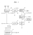
- FIG. 1 there is shown a block diagram of a conventional on-screen display apparatus for a VCR.
- the illustrated circuit comprises a programmable controller 31 for providing a plurality of control signals necessary to the VCR in accordance with a selection of the user, a radio frequency (RF) converter 32 for receiving an external broadcasting signal through a receiving antenna ANT1 and outputting a desired signal through a transmitting antenna ANT2 under a control of the programmable controller 31, a tuner 33 for tuning the broadcasting signal from the RF converter 32 to a broadcasting channel required by the user under a control of the programmable controller 31, demodulating the tuned broadcasting signal to divide it into a video signal and an audio signal AU and outputting the divided video signal and audio signal AU, a switching circuit 34 for selectively outputting one of the video signal from the tuner 33 and an external video signal under a control of the programmable controller 31, a luminance/chrominance (Y/C) processing circuit 35 for video-processing an output signal from the switching circuit 34 or
- the programmable controller 31 provides a plurality of control signals necessary to the VCR in accordance with the selection of the user.
- the radio frequency (RF) converter 32 receives the external broadcasting signal through the receiving antenna ANT1 and transmits the received broadcasting signal to the tuner 33. Also, the RF converter 32 outputs a desired signal through the transmitting antenna ANT2 in accordance with a control signal TV/VCR from the programmable controller 31. Namely, in a television (TV) mode, the RF converter 32 outputs the broadcasting signal inputted through the receiving antenna ANT1 directly through the transmitting antenna ANT2 externally, otherwise, in a VCR mode, the RF converter 32 modulates the video signal and caption signal from the buffer 37 to a broadcasting frequency required by the user and outputs the modulated video signal and caption signal through the transmitting antenna ANT2.
- TV television
- VCR VCR mode
- the tuner 33 tunes the broadcasting signal from the RF converter 32 to a broadcasting channel required by the user in accordance with a control signal D1 from the programmable controller 31, demodulates the tuned broadcasting signal to divide it into the video signal and the audio signal AU and outputs the divided video signal and audio signal AU. Then, the audio signal AU is transferred to an audio processing circuit (not shown) and the video signal is transferred to the switching circuit 34.
- the switching circuit 34 selectively outputs one of the video signal from the tuner 33 and an external video signal through a video input jack VIJ to the Y/C processing circuit 35 in accordance with a control signal Tuner/Line from the programmable controller 31. Namely, in a Tuner mode, the switching circuit 34 outputs the video signal from the tuner 33, otherwise, in a Line mode, the switching circuit 34 outputs the external video signal inputted through a video input jack VIJ.
- the Y/C processing circuit 35 video-processes the output signal from the switching circuit 34 or a self-video signal to be played back in accordance with a control signal VV/EE from the programmable controller 31. Namely, in a W mode, the Y/C processing circuit 35 outputs the self-video signal to be played back. Otherwise, in an EE mode, the Y/C processing circuit 35 outputs the output signal from the switching circuit 34.
- the on-screen display unit 36 displays the output signal from the Y/C processing circuit 35 and the caption signal from the separate caption decoder 38 in accordance with a control signal D2 from the programmable controller 31. Namely, upon an enable state of the control signal D2 from the programmable controller 31, the on-screen display unit 36 displays the output signal from the Y/C processing circuit 35. At this time, if the caption signal is applied from the separate caption decoder 38 during the display of the video signal from the Y/C processing circuit 35, the on-screen display unit 36 stops displaying the video signal from the Y/C processing circuit 35 and displays the caption signal from the separate caption decoder 38.
- the on-screen display unit 36 displays the video signal from the Y/C processing circuit 35 again.
- the on-screen display unit 36 outputs the output signal from the Y/C processing circuit 35 and the caption signal from the separate caption decoder 38 to the buffer 37.
- the broadcasting signal may mean a character multiplex broadcasting signal containing video, audio and caption signals.
- the video signal from the Y/C processing circuit 35 may contain the caption signal.
- the caption signal cannot be detected from the video signal from the Y/C processing circuit 35 without the separate caption decoder 38.
- the caption signal from the separate caption decoder 38 is displayed together with the video signal and audio signal.
- the buffer 37 buffers the received video signal and caption signal and then sends the buffered video signal and caption signal to the RF converter 32 and also outputs them through the video output jack VOJ externally.
- the conventional VCR with the above-mentioned on-screen display apparatus has a disadvantage, in that the caption decoder must be installed on the outside of the VCR, separately from the on-screen display apparatus, in order to detect the caption signal from the broadcasting signal, or character multiplex broadcasting signal, or the caption signal recorded on the VCR tape. For this reason, the deaf person or foreign language learner can not help purchasing the caption decoder separately and connecting the separate caption decoder to the VCR, so as to watch a desired image containing the caption on the screen. Therefore, it is inconvenient for the deaf person or foreign language learner to watch a desired image containing the caption signal on the screen utilizing the separate caption decoder.
- DE-C-33 15 687 Another example of the prior art is shown in DE-C-33 15 687 in which there is described a TV receiver having a video text decoder capable of detecting a caption signal. Once detected, the caption signal is combined with a video signal and either used to control a CRT or else recorded using a VCR. Once recorded, however, it is no longer possible for the caption signal to be processed separately from the combined caption and video signal.
- a caption display apparatus for a VCR comprising: programmable control means for providing a plurality of control signals under the control of a user; radio frequency converting means for receiving an external broadcast signal and outputting the received broadcast signal or a desired signal under the control of said programmable control means; tuning means for tuning said radio frequency converting means to a broadcasting channel required by the user under the control of said programmable control means, demodulating the tuned signal and dividing the demodulated signal into a video signal and an audio signal and outputting the divided video and audio signals; first switching means for selectively outputting one of the video signal from said tuning means and an external video signal under the control of said programmable control means; luminance/chrominance processing means for selectively video-processing one of an output signal from said first switching means or a pre-recorded video signal to be played back under the control of said programmable control means; luminance/chrominance detecting means for outputting a desired control signal (DH) to said programmable
- a caption signal in a caption VCR in conjunction with a video signal comprising the steps of:
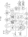
- the caption display apparatus comprises a programmable controller 1 for providing a plurality of control signals necessary to the VCR in accordance with a control signal D3 from the user, a radio frequency (RF) converter 2 for receiving an external broadcasting signal through a receiving antenna ANT1 and outputting a desired signal through a transmitting antenna ANT2 under a control of the programmable controller 1, a tuner 3 for tuning the broadcasting signal from the RF converter 2 to a broadcasting channel required by the user under a control of the programmable controller 1, demodulating the tuned broadcasting signal to divide it into a video signal and an audio signal AU and outputting the divided video signal and audio signal AU, a first switching circuit 4 for selectively outputting one of the video signal from the tuner 3 and an external video signal under a control of the programmable controller 1, a luminance/chrominance (Y/C) processing circuit 5 for
- the noise attenuator 8 includes a buffer 9 for buffering the output signal from the Y/C processing circuit 5, a color and noise removing circuit 10 for removing the color and noise contained in an output signal from the buffer 9 to prevent generation of an error character due to the color and noise upon decoding of a caption signal, and a clamping and synchronization correcting circuit 11 for clamping an output signal from the color and noise removing circuit 10 at a constant voltage level and then correcting a synchronization of the clamped signal to suppress a horizontal vibration of a character of the caption signal to be decoded.
- the caption display apparatus comprises a caption decoder 12 for inputting an output signal from the clamping and synchronization correcting circuit 11 in the noise attenuator 8 and detecting the caption signal containing screen data and character data from the output signal under a control of the programmable controller 1, a second switching circuit 13 for selectively outputting one of an output signal from the clamping circuit 7 and an output signal from the caption decoder 12 under a control of the caption decoder 12, a DC voltage supplying circuit 14 for supplying a desired DC voltage to the second switching circuit 13 only when the caption signal from the caption decoder 12 is applied to the second switching circuit 13, a buffer 15 for buffering an output signal from the second switching circuit 13, a on-screen display unit 16 for displaying the output signal from the second switching circuit through the buffer 15 or outputting it via a buffer 17 to the R/F converter 2 or through a video output jack VOJ externally under a control of the programmable controller 1 and a control of the Y/C detector 6, a third switching circuit 18 for blocking the output
- the second switching circuit 13 includes a first switch 13a for selectively outputting one of the output signal from the clamping circuit 7 and the screen data of the caption signal from the caption decoder 12 under the control of the caption decoder 12, and a second switch 13b for selectively outputting one of an output signal from the first switch 13a and the character data of the caption signal from the caption decoder 12 under the control of the caption decoder 12.
- the DC voltage supplying circuit 14 includes a first DC voltage supplying unit 14a for supplying a desired DC voltage to the first switch 13a in the second switching circuit 13 only when the screen data of the caption signal from the caption decoder 12 is applied to the first switch 13a, and a second DC voltage supplying unit 14b for supplying a desired DC voltage to the second switch 13b in the second switching circuit 13 only when the character data of the caption signal from the caption decoder 12 is applied to the second switch 13b.
- the third switching circuit 18 includes a third switch 18a for blocking the character data of the output signal from the caption decoder 12 to the second switch 13b in the second switching circuit 13 under the control of the programmable controller 1, and a fourth switch 18b for blocking the screen data of the output signal from the caption decoder 12 to the first switch 13a in the second switching circuit 13 under the control of the programmable controller 1.
- the reverse voltage preventing circuit 19 is provided with a pair of diodes D13 and D14 to prevent reverse voltages of the caption control signals SCS ⁇ and CCS ⁇ from the programmable controller 1.
- the diode 13 is connected between connection of the diode D12 with the inverter gate I12 and the third switch 18a in the third switching circuit 18.
- the diode 14 is connected between connection of the diode D11 with the inverter gate I11 and the fourth switch 18b in the third switching circuit 18.
- the programmable controller 1 provides a plurality of control signals necessary to the VCR in accordance with the selection of the user.
- the radio frequency (RF) converter 2 receives the external broadcasting signal through the receiving antenna ANT1 and transmits the broadcasting signal to the tuner 3.
- the broadcasting signal may mean a character multiplex broadcasting signal containing video, audio and caption signals.
- the video signal from the Y/C processing circuit 5 may contain the caption.
- the tuner 3 tunes the broadcasting signal from the RF converter 2 to a broadcasting channel required by the user in accordance with a control signal D1 from the programmable controller 1, demodulates the tuned broadcasting signal to divide it into the video signal and the audio signal AU and outputs the divided video signal and audio signal AU. Then, the audio signal AU is transferred to an audio processing circuit (not shown) and the video signal is transferred to the first switching circuit 4.
- the first switching circuit 4 selectively outputs one of the video signal from the tuner 3 and an external video signal through a video input jack VIJ to the Y/C processing circuit 5 in accordance with a control signal Tuner/Line from the programmable controller 1. Namely, in a Tuner mode, the first switching circuit 4 outputs the video signal from the tuner 3, otherwise, in a Line mode, the first switching circuit 4 outputs the external video signal inputted through a video input jack VIJ.
- the Y/C processing circuit 5 video-processes the output signal from the first switching circuit 4 or a self-video signal to be played back in accordance with a control signal VV/EE from the programmable controller 1. Namely, in a W mode, the Y/C processing circuit 5 outputs the self-video signal to be played back. Otherwise, in an EE mode, the Y/C processing circuit 5 outputs the output signal from the first switching circuit 4.
- the Y/C detector 6 outputs a desired control signal to the programmable controller 1 according to whether the output signal, or video signal from the Y/C processing circuit 5 is present. Namely, upon receiving the video signal from the Y/C processing circuit 5, the Y/C detector 6 outputs a high control signal DH to the programmable controller 1, which indicates that the video signal from the Y/C processing circuit 5 is present. Also, the Y/C detector 6 separates vertical and horizontal synchronous signals Vsync and Hsync from the video signal from the Y/C processing circuit 5, which are then applied to the on-screen display unit 16 for adjustment of a synchronization of the video signal. The vertical and horizontal synchronous signals Vsync and Hsync will later be mentioned in detail.
- the clamping circuit 7 clamps the video signal outputted from the Y/C processing circuit 5 at a constant voltage level and outputs the clamped video signal as shown in Fig. 5a to the second switching circuit 13.
- the video signal from the Y/C processing circuit 5 is applied to the buffer 9 in the noise attenuator 8, which functions as a low pass filter.
- the video signal from the Y/C processing circuit 5 is applied respectively to the Y/C detector 6, the clamping circuit 7 and the buffer 9 in the noise attenuator 8.
- the video signal from the clamping circuit 7, in which the caption signal is not detected, is applied to the on-screen display unit 16 through the second switching circuit 13.
- the color and noise removing circuit 10 in the noise attenuator 8 Upon receiving the buffered video signal from the buffer 9, the color and noise removing circuit 10 in the noise attenuator 8 removes the color and noise contained in the video signal from the buffer 9 to prevent generation of an error character due to the color and noise upon decoding of the caption signal. Then, the clamping and synchronization correcting circuit 11 in the noise attenuator 8 clamps the color and noise removed video signal from the color and noise removing circuit 10 at a constant voltage level and then corrects a synchronization of the clamped video signal to suppress a horizontal vibration of a character of the caption signal to be decoded. In result, the noise attenuator 8 enables the caption decoder 12 to readily find out the caption signal contained in the video signal.
- the fourth switch 18b in the third switching circuit 18 is turned off and a high signal through the inverter gate I11 is applied to the caption decoder 12.
- the serial screen data of the caption signal as shown in Fig. 5b is outputted from the caption decoder 12, which is then applied to the first switch 13a in the second switching circuit 13.
- a movable terminal c1 is normally connected to one fixed terminal a1 for apply of the video signal from the clamping circuit 7 to the second switch 13b in the second switching circuit 13.
- the movable terminal c1 of the first switch 13a is connected to the other fixed terminal b1 thereof. This connection of the movable terminal c1 to the other fixed terminal b1 in the first switch 13a is established only during the apply of the screen data of the caption signal from the caption decoder 12.
- a desired DC voltage fixing a level of the screen data of the caption signal is applied to the first switch 13a in the second switching circuit 13 from the first DC voltage supplying unit 14a in the DC voltage supplying circuit 14 which is connected to the other fixed terminal b1 of the first switch 13a.
- the screen data of the caption signal of frequency as shown in Fig. 5c is outputted from the first switch 13a to the second switch 13b in the second switching circuit 13.
- the fourth switch 18b in the third switching circuit 18 is turned on, thereby allowing the screen data output of the caption decoder 12 to be connected to the ground. Also, a low signal through the inverter gate I11 is applied to the caption decoder 12. As a result, no screen data of the caption signal is outputted from the caption decoder 12 and thus the first switch 13a in the second switching circuit 13 outputs the video signal from the clamping circuit 7 directly to the second switch 13b in the second switching circuit 13.
- the third switch 18a in the third switching circuit 18 is turned off and a high signal through the inverter gate I12 is applied to the caption decoder 12.
- the serial character data of the caption signal as shown in Fig. 5d is outputted from the caption decoder 12, which is then applied to the second switch 13b in the second switching circuit 13.
- Figs. 5b and 5d are waveform diagrams illustrating respectively levels of the serial screen data and serial character data of the caption signal outputted from the caption decoder 12.
- a movable terminal c2 is normally connected to one fixed terminal a2 for apply of the output signal from the first switch 13a, i.e., the video signal from the clamping circuit 7 or the screen data of the caption signal from the caption decoder 12 to the on-screen display unit 16 therethrough.
- the movable terminal c2 of the second switch 13b is connected to the other fixed terminal b2 thereof. This connection of the movable terminal c2 to the other fixed terminal b2 in the second switch 13b is established only during the apply of the character data of the caption signal from the caption decoder 12.
- a desired DC voltage fixing a level of the character data of the caption signal is applied to the second switch 13b in the second switching circuit 13 from the second DC voltage supplying unit 14b in the DC voltage supplying circuit 14 which is connected to the other fixed terminal b2 of the second switch 13b.
- the character data of the caption signal is outputted from the second switch 13b to the on-screen display unit 16 through the buffer 15.
- the third switch 18a in the third switching circuit 18 is turned on, thereby allowing the character data output of the caption decoder 12 to be connected to the ground. Also, a low signal through the inverter gate I12 is applied to the caption decoder 12. As a result, no character data of the caption signal is outputted from the caption decoder 12 and thus the second switch 13b in the second switching circuit 13 outputs the output signal from the first switch 13a, i.e., the video signal from the clamping circuit 7 or the screen data of the caption signal from the caption decoder 12 directly to the on-screen display unit 16 through the buffer 15.
- Fig. 5e is a waveform diagram illustrating levels of the serial screen data and serial character data of the caption signal outputted from the second switch 13b.
- Fig. 3 in which is shown a logic table illustrating logic states of the caption control signals CCS ⁇ and SCS ⁇ from the programmable controller 1, in accordance with the logic states of the caption control signals CCS ⁇ and SCS ⁇ , the second switch 13b in the second switching circuit 13 outputs only the normal video signal in a normal mode, or the screen data of the caption signal being added to the normal video signal in a screen mode, or the character data of the caption signal being added to the normal video signal and the screen data in a character mode.
- Fig. 4a illustrates a picture displayed on the screen of the on-screen display unit 16 including the screen data and character data of the caption signal and Fig. 4b illustrates an area on the screen in which the screen data and character data of the caption signal is displayed at the maximum.
- characters "This is a pen” corresponds to the character level shown in Fig. 5e.
- the lateral portion A of the screen area (A x B) surrounding the characters "This is a pen” corresponds to the screen region shown in Fig. 5e.
- the screen data of the caption signal outputted from the caption decoder 12 is displayed on the screen as a black color of the whole area on the screen or the rectangular area surrounding the characters "This is a pen” as shown in Figs. 4b and 4a.
- the character data of the caption signal is displayed on the screen by a squarewave pulse shown in Fig. 5e.
- the character data of the caption signal is displayed as a white color when the squarewave pulse is high, while as a black color when the squarewave pulse is low, as indicated as the characters "This is a pen" shown in Figs. 4a (wherein, for easiness of understanding of the screen data and character data of the caption signal with reference to Fig.4a, the screen data is shown as the white color and the character data is shown as the black color).
- the caption decoder 12 outputs only screen data of the caption signal, as mentioned above, if the user selects the screen mode by means of a remote controller 1a, the characters "This is a pen" as shown in Fig. 4a is not displayed on the screen and the corresponding area is displayed as the black color. Therefore, the user may not intentionally watch the characters on the screen for the purpose of hearing of the audio signal. Also, the modes in the logic table shown in Fig. 3 can be selected by the user utilizing the remote controller 1a.
- the movable terminals c1 and c2 of the first and second switches 13a and 13b in the second switching circuit 13 are connected respectively to the fixed terminals a1 and a2 since no caption signal from the caption decoder 12 is outputted to the first and second switches 13a and 13b.
- the clamping circuit 7 is outputted through the first and second switches 13a and 13b to the on-screen display unit 16. For this reason, in the normal mode, the character multiplex broadcasting function cannot be performed.
- the buffer 15 functions to buffer the output signal from the second switch 13b in the second switching circuit 13 and output the buffered signal to the on-screen display unit 16.
- the on-screen display unit 16 displays the output signal, i.e., video signal or caption signal from the second switch 13b in the second switching circuit 13 inputted through the buffer 15 in accordance with a control signal D2 from the programmable controller 1. Namely, upon an enable state of the control signal D2 from the programmable controller 1, the on-screen display unit 16 displays the output signal from the second switch 13b. At this time, if the caption signal, i.e., character data and screen data is applied from the second switch 13b during the display of the video signal previously outputted from the second switch 13b, the on-screen display unit 16 stops displaying the video signal and displays the caption signal.
- the caption signal i.e., character data and screen data
- the on-screen display unit 16 displays the video signal from the second switch 13b again.
- the on-screen display unit 16 outputs the output signal from the second switch 13b inputted through the buffer 15 to the buffer 17.
- the synchronization of the video signal including the caption signal is adjusted in accordance with the vertical and horizontal synchronous signals Vsync and Hsync outputted from Y/C detector 6. If no vertical and horizontal synchronous signals Vsync and Hsync are outputted from Y/C detector 6, the synchronization of the video signal including the caption signal is self-adjusted in the on-screen display unit 16.
- the buffer 17 buffers the received video signal including the caption signal and then sends the buffered video signal including caption signal to the RF converter 2 and also outputs them through the video output jack VOJ externally.
- the RF converter 2 outputs a desired signal through the transmitting antenna ANT2 in accordance with a control signal TV/VCR from the programmable controller 1.
- the RF converter 2 in a television (TV) mode, the RF converter 2 outputs the external broadcasting signal inputted through the receiving antenna ANT1 directly through the transmitting antenna ANT2 externally, otherwise, in a VCR mode, the RF converter 2 modulates the video signal including the caption signal from the buffer 17 and the audio signal from the audio processing circuit (not shown) to a broadcasting frequency required by the user and outputs the modulated video signal including caption signal and audio signal through the transmitting antenna ANT2.
- TV television
- the RF converter 2 in a VCR mode, the RF converter 2 modulates the video signal including the caption signal from the buffer 17 and the audio signal from the audio processing circuit (not shown) to a broadcasting frequency required by the user and outputs the modulated video signal including caption signal and audio signal through the transmitting antenna ANT2.
- the reverse voltage preventing circuit 19 functions to prevent reverse voltages of the caption control signals SCS ⁇ and CCS ⁇ from the programmable controller 1 when they are active "low".
- the programmable controller 1 may be under a remote control of the remote controller 1a. Even in a case where the system is in an operation other than speed change modes such as extend play (EP) mode, standard play (SP) mode and long play (LP) mode, the programmable controller 1 outputs a change speed signal VS of high level, thereby enabling the third and fourth switches 18a and 18b in the third switching circuit 18 to be shorted. As a result, the screen data and character data of the caption signal from the caption decoder 12 cannot be transferred to the second switching circuit 13.
- speed change modes such as extend play (EP) mode, standard play (SP) mode and long play (LP) mode
- FIG. 6 there is shown a flowchart illustrating the operation of one embodiment of the caption display apparatus.
- the RF converter 2 transmits the received broadcasting signal to the tuner 3.
- the tuner 3 tunes the broadcasting signal from the RF converter 2 to a broadcasting channel required by the user under the control of the programmable controller 1, demodulates the tuned broadcasting signal to divide it into the video signal and the audio signal AU and outputs the divided video signal and audio signal AU. Then, the audio signal AU is transferred to the audio processing circuit (not shown) and the video signal is transferred to the first switching circuit 4.
- the first switching circuit 4 selectively outputs one of the video signal from the tuner 3 and an external video signal through the video input jack VIJ to the Y/C processing circuit 5 under the control of the programmable controller 1.
- the Y/C processing circuit 5 video-processes the video signal from the first switching circuit 4 or the self-video signal to be played back under the control of the programmable controller 1. Then, the video signal from the Y/C processing circuit 5 is outputted to the clamping circuit 7 which clamps the received video signal at a constant voltage level. Also, the video signal from the Y/C processing circuit 5 is received by the caption decoder 12 which detects the caption signal from the received video signal. Further, the video signal from the Y/C processing circuit 5 is received by the Y/C detector 6 which confirms output. of the video signal from the Y/C processing circuit 5.
- the Y/C detector 6 Upon receiving the video signal from the Y/C processing circuit 5, the Y/C detector 6 outputs the high control signal DH to the programmable controller 1, which indicates that the video signal from the Y/C processing circuit 5 is present. Also, the Y/C detector 6 separates vertical and horizontal synchronous signals Vsync and Hsync from the video signal from the Y/C processing circuit 5 and applies the vertical and horizontal synchronous signals Vsync and Hsync to the on-screen display unit 16.
- the second switching circuit 13 normally operates to output the video signal from the clamping circuit 7 to the on-screen display unit 16. At this time, if the caption signal including the character and screen data is applied from the caption decoder 12, the second switching circuit 13 stops transferring the video signal from the clamping circuit 7 to the on-screen display unit 16 and transfers the caption signal from the caption decoder 12 to the on-screen display unit 16. Namely, if the screen data of the caption signal is applied from the caption decoder 12, it is transferred through the first and second switches 13a and 13b in the second switching circuit 13 to the on-screen display unit 16. If character data of the caption signal is applied from the caption decoder 12, it is transferred through the second switch 13b in the second switching circuit 13 to the on-screen display unit 16.
- the operation of the second switching circuit 13 is returned to the normal state in which the video signal from the clamping circuit 7 is transferred through the first and second switches 13a and 13b in the second switching circuit 13 to the on-screen display unit 16.
- the output signal from the on-screen display unit 16 is transferred to the RF converter 2 or to the video output jack VOJ externally.
- the RF converter 2 modulates the video signal including the caption signal from the buffer 17 and the audio signal from the audio processing circuit (not shown) to a broadcasting frequency required by the user and outputs the modulated video signal including caption signal and audio signal through the transmitting antenna ANT2.
- the caption VCR having the caption decoder, therein, for detecting the caption signal from the broadcasting signal or detecting the caption signal recorded on the VCR tape. Also, there is provided the method of displaying the caption signal from the caption decoder together with the audio signal and the video signal in the caption VCR. Therefore, according to the present invention, it is convenient for the deaf person or foreign language learner to watch a desired image containing the caption signal on the screen utilizing the caption decoder.
Description
- The present invention relates in general to video cassette recorders (VCR), and more particularly to video cassette recorders adapted for use with a caption decoder for detecting a caption signal from a broadcasting signal or detecting the caption signal recorded on a VCR tape and to a method of displaying the caption signal from the caption decoder together with an audio signal and a video signal in the caption VCR.
- For the purpose of further display of a caption signal in a VCR in which an audio signal and a video signal are displayed, a deaf person or a foreign language learner usually detects the caption signal from a broadcasting signal containing the caption signal or detects the caption signal recorded on a VCR tape, utilizing a separate, external caption decoder. Then, the detected caption signal from the caption decoder is displayed together with the audio and video signals in the VCR.
- With reference to Fig. 1, there is shown a block diagram of a conventional on-screen display apparatus for a VCR. The illustrated circuit comprises a
programmable controller 31 for providing a plurality of control signals necessary to the VCR in accordance with a selection of the user, a radio frequency (RF)converter 32 for receiving an external broadcasting signal through a receiving antenna ANT1 and outputting a desired signal through a transmitting antenna ANT2 under a control of theprogrammable controller 31, atuner 33 for tuning the broadcasting signal from theRF converter 32 to a broadcasting channel required by the user under a control of theprogrammable controller 31, demodulating the tuned broadcasting signal to divide it into a video signal and an audio signal AU and outputting the divided video signal and audio signal AU, aswitching circuit 34 for selectively outputting one of the video signal from thetuner 33 and an external video signal under a control of theprogrammable controller 31, a luminance/chrominance (Y/C)processing circuit 35 for video-processing an output signal from theswitching circuit 34 or a self-video signal to be played back under a control of theprogrammable controller 31, an on-screen display unit 36 for displaying an output signal from the Y/C processing circuit 35 and an external caption signal under a control of theprogrammable controller 31, abuffer 37 for buffering an output signal from the on-screen display unit 36 and outputting the buffered signal through theRF converter 32 and through a video output jack VOJ externally, and aseparate caption decoder 38 for detecting the caption signal from the broadcasting signal or the caption signal recorded on a VCR tape and the detected caption signal to the on-screen display unit 36. - The operation of the on-screen display apparatus for the VCR with the above-mentioned construction will now be described.
- The
programmable controller 31 provides a plurality of control signals necessary to the VCR in accordance with the selection of the user. - The radio frequency (RF)
converter 32 receives the external broadcasting signal through the receiving antenna ANT1 and transmits the received broadcasting signal to thetuner 33. Also, theRF converter 32 outputs a desired signal through the transmitting antenna ANT2 in accordance with a control signal TV/VCR from theprogrammable controller 31. Namely, in a television (TV) mode, theRF converter 32 outputs the broadcasting signal inputted through the receiving antenna ANT1 directly through the transmitting antenna ANT2 externally, otherwise, in a VCR mode, theRF converter 32 modulates the video signal and caption signal from thebuffer 37 to a broadcasting frequency required by the user and outputs the modulated video signal and caption signal through the transmitting antenna ANT2. - The
tuner 33 tunes the broadcasting signal from theRF converter 32 to a broadcasting channel required by the user in accordance with a control signal D1 from theprogrammable controller 31, demodulates the tuned broadcasting signal to divide it into the video signal and the audio signal AU and outputs the divided video signal and audio signal AU. Then, the audio signal AU is transferred to an audio processing circuit (not shown) and the video signal is transferred to theswitching circuit 34. - The
switching circuit 34 selectively outputs one of the video signal from thetuner 33 and an external video signal through a video input jack VIJ to the Y/C processing circuit 35 in accordance with a control signal Tuner/Line from theprogrammable controller 31. Namely, in a Tuner mode, theswitching circuit 34 outputs the video signal from thetuner 33, otherwise, in a Line mode, theswitching circuit 34 outputs the external video signal inputted through a video input jack VIJ. - The Y/
C processing circuit 35 video-processes the output signal from theswitching circuit 34 or a self-video signal to be played back in accordance with a control signal VV/EE from theprogrammable controller 31. Namely, in a W mode, the Y/C processing circuit 35 outputs the self-video signal to be played back. Otherwise, in an EE mode, the Y/C processing circuit 35 outputs the output signal from theswitching circuit 34. - The on-
screen display unit 36 displays the output signal from the Y/C processing circuit 35 and the caption signal from theseparate caption decoder 38 in accordance with a control signal D2 from theprogrammable controller 31. Namely, upon an enable state of the control signal D2 from theprogrammable controller 31, the on-screen display unit 36 displays the output signal from the Y/C processing circuit 35. At this time, if the caption signal is applied from theseparate caption decoder 38 during the display of the video signal from the Y/C processing circuit 35, the on-screen display unit 36 stops displaying the video signal from the Y/C processing circuit 35 and displays the caption signal from theseparate caption decoder 38. Then, if no further caption signal is applied from theseparate caption decoder 38, the on-screen display unit 36 displays the video signal from the Y/C processing circuit 35 again. On the other hand, upon a disable state of the control signal D2 from theprogrammable controller 31, the on-screen display unit 36 outputs the output signal from the Y/C processing circuit 35 and the caption signal from theseparate caption decoder 38 to thebuffer 37. - Herein, the broadcasting signal may mean a character multiplex broadcasting signal containing video, audio and caption signals. Also, the video signal from the Y/
C processing circuit 35 may contain the caption signal. However, in the conventional VCR, the caption signal cannot be detected from the video signal from the Y/C processing circuit 35 without theseparate caption decoder 38. - Therefore, in this manner, the caption signal from the
separate caption decoder 38 is displayed together with the video signal and audio signal. - On the other hand, upon receiving the video signal and caption signal from the on-
screen display unit 36, thebuffer 37 buffers the received video signal and caption signal and then sends the buffered video signal and caption signal to theRF converter 32 and also outputs them through the video output jack VOJ externally. - However, the conventional VCR with the above-mentioned on-screen display apparatus has a disadvantage, in that the caption decoder must be installed on the outside of the VCR, separately from the on-screen display apparatus, in order to detect the caption signal from the broadcasting signal, or character multiplex broadcasting signal, or the caption signal recorded on the VCR tape. For this reason, the deaf person or foreign language learner can not help purchasing the caption decoder separately and connecting the separate caption decoder to the VCR, so as to watch a desired image containing the caption on the screen. Therefore, it is inconvenient for the deaf person or foreign language learner to watch a desired image containing the caption signal on the screen utilizing the separate caption decoder.
- Another example of the prior art is shown in DE-C-33 15 687 in which there is described a TV receiver having a video text decoder capable of detecting a caption signal. Once detected, the caption signal is combined with a video signal and either used to control a CRT or else recorded using a VCR. Once recorded, however, it is no longer possible for the caption signal to be processed separately from the combined caption and video signal.
- According to a first aspect of the present invention there is provided a caption display apparatus for a VCR, comprising: programmable control means for providing a plurality of control signals under the control of a user; radio frequency converting means for receiving an external broadcast signal and outputting the received broadcast signal or a desired signal under the control of said programmable control means; tuning means for tuning said radio frequency converting means to a broadcasting channel required by the user under the control of said programmable control means, demodulating the tuned signal and dividing the demodulated signal into a video signal and an audio signal and outputting the divided video and audio signals; first switching means for selectively outputting one of the video signal from said tuning means and an external video signal under the control of said programmable control means; luminance/chrominance processing means for selectively video-processing one of an output signal from said first switching means or a pre-recorded video signal to be played back under the control of said programmable control means; luminance/chrominance detecting means for outputting a desired control signal (DH) to said programmable control means according to whether an output signal from said luminance/chrominance processing means is present and separating vertical and horizontal synchronous signals ( Vsync, Hsync) from the output signal from said luminance/chrominance processing means if the output signal from said luminance/chrominance processing means is present; clamping means for clamping the output signal from said luminance/chrominance processing means at a constant voltage level; noise attenuating means for attenuating a noise contained in the output signal from said luminance/chrominance processing means to facilitate decoding of a caption signal from the output signal from said luminance/chrominance processing means; caption decoding means for receiving an output signal from said noise attenuating means and detecting a caption signal containing screen data and character data under the control of said programmable control means; DC voltage supply means for supplying a desired DC voltage; second switching means for selectively outputting one of an output signal from said clamping means and said desired DC voltage from said DC voltage supply means in response to a caption signal from said caption decoding means; on-screen display means for displaying an output signal from said second switching means under the control of said programmable control means and said luminance/chrominance detecting means; and third switching means connected to both said caption decoding means and said second switching means for selectively blocking the caption signal output from said caption decoding means to said second switching means under the control of said programmable control means.
- According to a second aspect of the present invention there is provided a method of displaying a caption signal in a caption VCR in conjunction with a video signal, the method comprising the steps of:
- (a) luminance/chrominance-processing a video signal input into the VCR;
- (b) clamping the luminance/chrominance-processed video signal at a constant voltage level;
- (c) displaying the clamped video signal; and
- (d) decoding the luminance/chrominance-processed video signal to detect a caption signal from the luminance/chrominance-processed video signal,
- (e) decoding the caption signal to detect screen data and character data from the caption signal;
- (f) displaying a background determined by said screen data in place of a portion of said clamped video signal when said screen data is detected; and
- (g) displaying one or more characters determined by said character data in place of a portion of said background when said character data is detected.
- An example of one embodiment of the present invention will now be described with reference to the drawings, in which:-
- Fig. 1 is a block diagram of a conventional on-screen display apparatus for a VCR;
- Fig. 2 is a block diagram of a caption display apparatus for the VCR in accordance with one embodiment of the present invention;
- Fig. 3 is a logic table illustrating logic states of caption control signals from a programmable controller in Fig. 2;
- Fig. 4 is picture displayed on the screen of an on-screen display unit in Fig. 2 including screen data and character data of a caption signal, in accordance with an embodiment of the present invention, wherein:
- Fig. 4a illustrates a picture displayed on the screen including screen data and character data of the caption signal; and
- Fig. 4b illustrates an area on the screen in which the screen data and character data of the caption signal is displayed at the maximum;
- Fig. 5a through 5e are waveform diagrams illustrating respectively levels of the screen data and character data of the caption signal; and
- Fig. 6 is a flowchart illustrating the operation of the caption display apparatus in Fig. 2.
- First, a construction of a caption display apparatus for the VCR in accordance with one embodiment of the present invention will be described with reference to Fig. 2.
- With reference to Fig. 2, there is shown a block diagram of a caption display apparatus for the VCR in accordance with one embodiment. As shown in this drawing, the caption display apparatus comprises a
programmable controller 1 for providing a plurality of control signals necessary to the VCR in accordance with a control signal D3 from the user, a radio frequency (RF)converter 2 for receiving an external broadcasting signal through a receiving antenna ANT1 and outputting a desired signal through a transmitting antenna ANT2 under a control of theprogrammable controller 1, atuner 3 for tuning the broadcasting signal from theRF converter 2 to a broadcasting channel required by the user under a control of theprogrammable controller 1, demodulating the tuned broadcasting signal to divide it into a video signal and an audio signal AU and outputting the divided video signal and audio signal AU, a first switching circuit 4 for selectively outputting one of the video signal from thetuner 3 and an external video signal under a control of theprogrammable controller 1, a luminance/chrominance (Y/C) processing circuit 5 for video-processing an output signal from the switching circuit 4 or a self-video signal to be played back under a control of theprogrammable controller 1, a Y/C detector 6 for outputting a desired control signal to theprogrammable controller 1 according to whether an output signal from the Y/C processing circuit 5 is present and separating vertical and horizontal synchronous signals from the output signal from the Y/C processing circuit 5 if the output signal from the Y/C processing circuit 5 is present, a clamping circuit 7 for clamping the output signal from the Y/C processing circuit 5 at a constant voltage level, and anoise attenuator 8 for attenuating a noise contained in the output signal from the Y/C processing circuit 5. - The
noise attenuator 8 includes a buffer 9 for buffering the output signal from the Y/C processing circuit 5, a color andnoise removing circuit 10 for removing the color and noise contained in an output signal from the buffer 9 to prevent generation of an error character due to the color and noise upon decoding of a caption signal, and a clamping andsynchronization correcting circuit 11 for clamping an output signal from the color andnoise removing circuit 10 at a constant voltage level and then correcting a synchronization of the clamped signal to suppress a horizontal vibration of a character of the caption signal to be decoded. - Also, the caption display apparatus comprises a
caption decoder 12 for inputting an output signal from the clamping andsynchronization correcting circuit 11 in thenoise attenuator 8 and detecting the caption signal containing screen data and character data from the output signal under a control of theprogrammable controller 1, a second switching circuit 13 for selectively outputting one of an output signal from the clamping circuit 7 and an output signal from thecaption decoder 12 under a control of thecaption decoder 12, a DC voltage supplying circuit 14 for supplying a desired DC voltage to the second switching circuit 13 only when the caption signal from thecaption decoder 12 is applied to the second switching circuit 13, abuffer 15 for buffering an output signal from the second switching circuit 13, a on-screen display unit 16 for displaying the output signal from the second switching circuit through thebuffer 15 or outputting it via abuffer 17 to the R/F converter 2 or through a video output jack VOJ externally under a control of theprogrammable controller 1 and a control of the Y/C detector 6, athird switching circuit 18 for blocking the output signal from thecaption decoder 12 to the second switching circuit 13 under a control of theprogrammable controller 1, and a reversevoltage preventing circuit 19 for preventing reverse voltages of caption control signals SCS and CCS from theprogrammable controller 1. - The second switching circuit 13 includes a
first switch 13a for selectively outputting one of the output signal from the clamping circuit 7 and the screen data of the caption signal from thecaption decoder 12 under the control of thecaption decoder 12, and asecond switch 13b for selectively outputting one of an output signal from thefirst switch 13a and the character data of the caption signal from thecaption decoder 12 under the control of thecaption decoder 12. - Also, the DC voltage supplying circuit 14 includes a first DC
voltage supplying unit 14a for supplying a desired DC voltage to thefirst switch 13a in the second switching circuit 13 only when the screen data of the caption signal from thecaption decoder 12 is applied to thefirst switch 13a, and a second DCvoltage supplying unit 14b for supplying a desired DC voltage to thesecond switch 13b in the second switching circuit 13 only when the character data of the caption signal from thecaption decoder 12 is applied to thesecond switch 13b. - The
third switching circuit 18 includes athird switch 18a for blocking the character data of the output signal from thecaption decoder 12 to thesecond switch 13b in the second switching circuit 13 under the control of theprogrammable controller 1, and afourth switch 18b for blocking the screen data of the output signal from thecaption decoder 12 to thefirst switch 13a in the second switching circuit 13 under the control of theprogrammable controller 1. - On the other hand, between a caption control signal

programmable controller 1 and thecaption decoder 12 are connected a diode D11 and an inverter gate I11 in series. Also, between a caption control signal
programmable controller 1 and thecaption decoder 12 are connected a diode D12 and an inverter gate I12 in series. - Also, the reverse
voltage preventing circuit 19 is provided with a pair of diodes D13 and D14 to prevent reverse voltages of the caption control signals

programmable controller 1. The diode 13 is connected between connection of the diode D12 with the inverter gate I12 and thethird switch 18a in thethird switching circuit 18. The diode 14 is connected between connection of the diode D11 with the inverter gate I11 and thefourth switch 18b in thethird switching circuit 18. - Now, the operation of the caption display apparatus with the above mentioned construction will be described in detail with reference to Figs. 3 through 6.
- The
programmable controller 1 provides a plurality of control signals necessary to the VCR in accordance with the selection of the user. - The radio frequency (RF)
converter 2 receives the external broadcasting signal through the receiving antenna ANT1 and transmits the broadcasting signal to thetuner 3. - Herein, the broadcasting signal may mean a character multiplex broadcasting signal containing video, audio and caption signals. Also, the video signal from the Y/C processing circuit 5 may contain the caption.
- The
tuner 3 tunes the broadcasting signal from theRF converter 2 to a broadcasting channel required by the user in accordance with a control signal D1 from theprogrammable controller 1, demodulates the tuned broadcasting signal to divide it into the video signal and the audio signal AU and outputs the divided video signal and audio signal AU. Then, the audio signal AU is transferred to an audio processing circuit (not shown) and the video signal is transferred to the first switching circuit 4. - The first switching circuit 4 selectively outputs one of the video signal from the
tuner 3 and an external video signal through a video input jack VIJ to the Y/C processing circuit 5 in accordance with a control signal Tuner/Line from theprogrammable controller 1. Namely, in a Tuner mode, the first switching circuit 4 outputs the video signal from thetuner 3, otherwise, in a Line mode, the first switching circuit 4 outputs the external video signal inputted through a video input jack VIJ. - The Y/C processing circuit 5 video-processes the output signal from the first switching circuit 4 or a self-video signal to be played back in accordance with a control signal VV/EE from the
programmable controller 1. Namely, in a W mode, the Y/C processing circuit 5 outputs the self-video signal to be played back. Otherwise, in an EE mode, the Y/C processing circuit 5 outputs the output signal from the first switching circuit 4. - The Y/C detector 6 outputs a desired control signal to the
programmable controller 1 according to whether the output signal, or video signal from the Y/C processing circuit 5 is present. Namely, upon receiving the video signal from the Y/C processing circuit 5, the Y/C detector 6 outputs a high control signal DH to theprogrammable controller 1, which indicates that the video signal from the Y/C processing circuit 5 is present. Also, the Y/C detector 6 separates vertical and horizontal synchronous signals Vsync and Hsync from the video signal from the Y/C processing circuit 5, which are then applied to the on-screen display unit 16 for adjustment of a synchronization of the video signal. The vertical and horizontal synchronous signals Vsync and Hsync will later be mentioned in detail. - The clamping circuit 7 clamps the video signal outputted from the Y/C processing circuit 5 at a constant voltage level and outputs the clamped video signal as shown in Fig. 5a to the second switching circuit 13.
- On the other hand, the video signal from the Y/C processing circuit 5 is applied to the buffer 9 in the
noise attenuator 8, which functions as a low pass filter. - Therefore, as mentioned above, the video signal from the Y/C processing circuit 5 is applied respectively to the Y/C detector 6, the clamping circuit 7 and the buffer 9 in the
noise attenuator 8. The video signal from the clamping circuit 7, in which the caption signal is not detected, is applied to the on-screen display unit 16 through the second switching circuit 13. - Upon receiving the buffered video signal from the buffer 9, the color and
noise removing circuit 10 in thenoise attenuator 8 removes the color and noise contained in the video signal from the buffer 9 to prevent generation of an error character due to the color and noise upon decoding of the caption signal. Then, the clamping andsynchronization correcting circuit 11 in thenoise attenuator 8 clamps the color and noise removed video signal from the color andnoise removing circuit 10 at a constant voltage level and then corrects a synchronization of the clamped video signal to suppress a horizontal vibration of a character of the caption signal to be decoded. In result, thenoise attenuator 8 enables thecaption decoder 12 to readily find out the caption signal contained in the video signal. - If the caption control signal, or screen control signal

programmable controller 1 is active "low", thefourth switch 18b in thethird switching circuit 18 is turned off and a high signal through the inverter gate I11 is applied to thecaption decoder 12. As a result, the serial screen data of the caption signal as shown in Fig. 5b is outputted from thecaption decoder 12, which is then applied to thefirst switch 13a in the second switching circuit 13. - In the
first switch 13a in the second switching circuit 13, a movable terminal c1 is normally connected to one fixed terminal a1 for apply of the video signal from the clamping circuit 7 to thesecond switch 13b in the second switching circuit 13. On the other hand, upon apply of the screen data of the caption signal from thecaption decoder 12, the movable terminal c1 of thefirst switch 13a is connected to the other fixed terminal b1 thereof. This connection of the movable terminal c1 to the other fixed terminal b1 in thefirst switch 13a is established only during the apply of the screen data of the caption signal from thecaption decoder 12. At this time, a desired DC voltage fixing a level of the screen data of the caption signal is applied to thefirst switch 13a in the second switching circuit 13 from the first DCvoltage supplying unit 14a in the DC voltage supplying circuit 14 which is connected to the other fixed terminal b1 of thefirst switch 13a. As a result, the screen data of the caption signal of frequency as shown in Fig. 5c is outputted from thefirst switch 13a to thesecond switch 13b in the second switching circuit 13. - On the other hand, if the caption control signal, or screen control signal

programmable controller 1 is inactive "high", thefourth switch 18b in thethird switching circuit 18 is turned on, thereby allowing the screen data output of thecaption decoder 12 to be connected to the ground. Also, a low signal through the inverter gate I11 is applied to thecaption decoder 12. As a result, no screen data of the caption signal is outputted from thecaption decoder 12 and thus thefirst switch 13a in the second switching circuit 13 outputs the video signal from the clamping circuit 7 directly to thesecond switch 13b in the second switching circuit 13. - Also, if the caption control signal, or character control signal

programmable controller 1 is active "low", thethird switch 18a in thethird switching circuit 18 is turned off and a high signal through the inverter gate I12 is applied to thecaption decoder 12. As a result, the serial character data of the caption signal as shown in Fig. 5d is outputted from thecaption decoder 12, which is then applied to thesecond switch 13b in the second switching circuit 13. - Figs. 5b and 5d are waveform diagrams illustrating respectively levels of the serial screen data and serial character data of the caption signal outputted from the
caption decoder 12. - In the
second switch 13b in the second switching circuit 13, a movable terminal c2 is normally connected to one fixed terminal a2 for apply of the output signal from thefirst switch 13a, i.e., the video signal from the clamping circuit 7 or the screen data of the caption signal from thecaption decoder 12 to the on-screen display unit 16 therethrough. On the other hand, upon apply of the character data of the caption signal from thecaption decoder 12, the movable terminal c2 of thesecond switch 13b is connected to the other fixed terminal b2 thereof. This connection of the movable terminal c2 to the other fixed terminal b2 in thesecond switch 13b is established only during the apply of the character data of the caption signal from thecaption decoder 12. At this time, a desired DC voltage fixing a level of the character data of the caption signal is applied to thesecond switch 13b in the second switching circuit 13 from the second DCvoltage supplying unit 14b in the DC voltage supplying circuit 14 which is connected to the other fixed terminal b2 of thesecond switch 13b. As a result, the character data of the caption signal is outputted from thesecond switch 13b to the on-screen display unit 16 through thebuffer 15. - On the other hand, if the caption control signal, or character control signal

programmable controller 1 is inactive "high", thethird switch 18a in thethird switching circuit 18 is turned on, thereby allowing the character data output of thecaption decoder 12 to be connected to the ground. Also, a low signal through the inverter gate I12 is applied to thecaption decoder 12. As a result, no character data of the caption signal is outputted from thecaption decoder 12 and thus thesecond switch 13b in the second switching circuit 13 outputs the output signal from thefirst switch 13a, i.e., the video signal from the clamping circuit 7 or the screen data of the caption signal from thecaption decoder 12 directly to the on-screen display unit 16 through thebuffer 15. - Fig. 5e is a waveform diagram illustrating levels of the serial screen data and serial character data of the caption signal outputted from the
second switch 13b. - Accordingly, as shown in Fig. 3 in which is shown a logic table illustrating logic states of the caption control signals


programmable controller 1, in accordance with the logic states of the caption control signals

second switch 13b in the second switching circuit 13 outputs only the normal video signal in a normal mode, or the screen data of the caption signal being added to the normal video signal in a screen mode, or the character data of the caption signal being added to the normal video signal and the screen data in a character mode. - Fig. 4a illustrates a picture displayed on the screen of the on-
screen display unit 16 including the screen data and character data of the caption signal and Fig. 4b illustrates an area on the screen in which the screen data and character data of the caption signal is displayed at the maximum. - For example, characters "This is a pen" corresponds to the character level shown in Fig. 5e. The lateral portion A of the screen area (A x B) surrounding the characters "This is a pen" corresponds to the screen region shown in Fig. 5e. As a result, the screen data of the caption signal outputted from the
caption decoder 12 is displayed on the screen as a black color of the whole area on the screen or the rectangular area surrounding the characters "This is a pen" as shown in Figs. 4b and 4a. The character data of the caption signal is displayed on the screen by a squarewave pulse shown in Fig. 5e. Namely, the character data of the caption signal is displayed as a white color when the squarewave pulse is high, while as a black color when the squarewave pulse is low, as indicated as the characters "This is a pen" shown in Figs. 4a (wherein, for easiness of understanding of the screen data and character data of the caption signal with reference to Fig.4a, the screen data is shown as the white color and the character data is shown as the black color). - On the other hand, since the
caption decoder 12 outputs only screen data of the caption signal, as mentioned above, if the user selects the screen mode by means of a remote controller 1a, the characters "This is a pen" as shown in Fig. 4a is not displayed on the screen and the corresponding area is displayed as the black color. Therefore, the user may not intentionally watch the characters on the screen for the purpose of hearing of the audio signal. Also, the modes in the logic table shown in Fig. 3 can be selected by the user utilizing the remote controller 1a. - In the normal mode, the movable terminals c1 and c2 of the first and
second switches caption decoder 12 is outputted to the first andsecond switches second switches screen display unit 16. For this reason, in the normal mode, the character multiplex broadcasting function cannot be performed. - The
buffer 15 functions to buffer the output signal from thesecond switch 13b in the second switching circuit 13 and output the buffered signal to the on-screen display unit 16. - The on-
screen display unit 16 displays the output signal, i.e., video signal or caption signal from thesecond switch 13b in the second switching circuit 13 inputted through thebuffer 15 in accordance with a control signal D2 from theprogrammable controller 1. Namely, upon an enable state of the control signal D2 from theprogrammable controller 1, the on-screen display unit 16 displays the output signal from thesecond switch 13b. At this time, if the caption signal, i.e., character data and screen data is applied from thesecond switch 13b during the display of the video signal previously outputted from thesecond switch 13b, the on-screen display unit 16 stops displaying the video signal and displays the caption signal. Then, if no further caption signal is applied from thesecond switch 13b, the on-screen display unit 16 displays the video signal from thesecond switch 13b again. On the other hand, upon a disable state of the control signal D2 from theprogrammable controller 1, the on-screen display unit 16 outputs the output signal from thesecond switch 13b inputted through thebuffer 15 to thebuffer 17. Also, in the on-screen display unit 16, the synchronization of the video signal including the caption signal is adjusted in accordance with the vertical and horizontal synchronous signals Vsync and Hsync outputted from Y/C detector 6. If no vertical and horizontal synchronous signals Vsync and Hsync are outputted from Y/C detector 6, the synchronization of the video signal including the caption signal is self-adjusted in the on-screen display unit 16. - Also, the
buffer 17 buffers the received video signal including the caption signal and then sends the buffered video signal including caption signal to theRF converter 2 and also outputs them through the video output jack VOJ externally. - In other words, the
RF converter 2 outputs a desired signal through the transmitting antenna ANT2 in accordance with a control signal TV/VCR from theprogrammable controller 1. Namely, in a television (TV) mode, theRF converter 2 outputs the external broadcasting signal inputted through the receiving antenna ANT1 directly through the transmitting antenna ANT2 externally, otherwise, in a VCR mode, theRF converter 2 modulates the video signal including the caption signal from thebuffer 17 and the audio signal from the audio processing circuit (not shown) to a broadcasting frequency required by the user and outputs the modulated video signal including caption signal and audio signal through the transmitting antenna ANT2. - The reverse
voltage preventing circuit 19 functions to prevent reverse voltages of the caption control signals

programmable controller 1 when they are active "low". - The
programmable controller 1 may be under a remote control of the remote controller 1a. Even in a case where the system is in an operation other than speed change modes such as extend play (EP) mode, standard play (SP) mode and long play (LP) mode, theprogrammable controller 1 outputs a change speed signal VS of high level, thereby enabling the third andfourth switches third switching circuit 18 to be shorted. As a result, the screen data and character data of the caption signal from thecaption decoder 12 cannot be transferred to the second switching circuit 13. - With reference to Fig. 6, there is shown a flowchart illustrating the operation of one embodiment of the caption display apparatus.
- First, upon receiving the external broadcasting signal containing the video signal and audio signal, the
RF converter 2 transmits the received broadcasting signal to thetuner 3. - The
tuner 3 tunes the broadcasting signal from theRF converter 2 to a broadcasting channel required by the user under the control of theprogrammable controller 1, demodulates the tuned broadcasting signal to divide it into the video signal and the audio signal AU and outputs the divided video signal and audio signal AU. Then, the audio signal AU is transferred to the audio processing circuit (not shown) and the video signal is transferred to the first switching circuit 4. - The first switching circuit 4 selectively outputs one of the video signal from the
tuner 3 and an external video signal through the video input jack VIJ to the Y/C processing circuit 5 under the control of theprogrammable controller 1. - The Y/C processing circuit 5 video-processes the video signal from the first switching circuit 4 or the self-video signal to be played back under the control of the
programmable controller 1. Then, the video signal from the Y/C processing circuit 5 is outputted to the clamping circuit 7 which clamps the received video signal at a constant voltage level. Also, the video signal from the Y/C processing circuit 5 is received by thecaption decoder 12 which detects the caption signal from the received video signal. Further, the video signal from the Y/C processing circuit 5 is received by the Y/C detector 6 which confirms output. of the video signal from the Y/C processing circuit 5. - Upon receiving the video signal from the Y/C processing circuit 5, the Y/C detector 6 outputs the high control signal DH to the
programmable controller 1, which indicates that the video signal from the Y/C processing circuit 5 is present. Also, the Y/C detector 6 separates vertical and horizontal synchronous signals Vsync and Hsync from the video signal from the Y/C processing circuit 5 and applies the vertical and horizontal synchronous signals Vsync and Hsync to the on-screen display unit 16. - The second switching circuit 13 normally operates to output the video signal from the clamping circuit 7 to the on-
screen display unit 16. At this time, if the caption signal including the character and screen data is applied from thecaption decoder 12, the second switching circuit 13 stops transferring the video signal from the clamping circuit 7 to the on-screen display unit 16 and transfers the caption signal from thecaption decoder 12 to the on-screen display unit 16. Namely, if the screen data of the caption signal is applied from thecaption decoder 12, it is transferred through the first andsecond switches screen display unit 16. If character data of the caption signal is applied from thecaption decoder 12, it is transferred through thesecond switch 13b in the second switching circuit 13 to the on-screen display unit 16. If no further screen and character data of the caption signal is applied from thecaption decoder 12, the operation of the second switching circuit 13 is returned to the normal state in which the video signal from the clamping circuit 7 is transferred through the first andsecond switches screen display unit 16. - On the other hand, the output signal from the on-
screen display unit 16 is transferred to theRF converter 2 or to the video output jack VOJ externally. In the VCR mode, theRF converter 2 modulates the video signal including the caption signal from thebuffer 17 and the audio signal from the audio processing circuit (not shown) to a broadcasting frequency required by the user and outputs the modulated video signal including caption signal and audio signal through the transmitting antenna ANT2. - As hereinbefore described, in accordance with the present invention, there is provided the caption VCR having the caption decoder, therein, for detecting the caption signal from the broadcasting signal or detecting the caption signal recorded on the VCR tape. Also, there is provided the method of displaying the caption signal from the caption decoder together with the audio signal and the video signal in the caption VCR. Therefore, according to the present invention, it is convenient for the deaf person or foreign language learner to watch a desired image containing the caption signal on the screen utilizing the caption decoder.
- Although the preferred embodiments of the present invention have been disclosed for illustrative purpose, those skilled in the art will appreciate that various modifications, additions and substitutions are possible, without departing from the scope of the invention as disclosed in the accompanying claims.
Claims (9)
- A caption display apparatus for a VCR, comprising:programmable control means (1) for providing a plurality of control signals under the control of a user;radio frequency converting means (2) for receiving an external broadcast signal and outputting the received broadcast signal or a desired signal under the control of said programmable control means (1);tuning means (3) for tuning said radio frequency converting means (2) to a broadcasting channel required by the user under the control of said programmable control means (1), demodulating the tuned signal and dividing the demodulated signal into a video signal and an audio signal and outputting the divided video and audio signals;first switching means (4) for selectively outputting one of the video signal from said tuning means (3) and an external video signal under the control of said programmable control means (1);luminance/chrominance processing means (5) for selectively video-processing one of an output signal from said first switching means (4) or a pre-recorded video signal to be played back under the control of said programmable control means (1);luminance/chrominance detecting means (6) for outputting a desired control signal (DH) to said programmable control means (1) according to whether an output signal from said luminance/chrominance processing means (5) is present and separating vertical and horizontal synchronous signals ( Vsync, Hsync) from the output signal from said luminance/chrominance processing means (5) if the output signal from said luminance/chrominance processing means (5) is present;clamping means (7) for clamping the output signal from said luminance/chrominance processing means (5) at a constant voltage level;noise attenuating means (8) for attenuating a noise contained in the output signal from said luminance/chrominance processing means (5) to facilitate decoding of a caption signal from the output signal from said luminance/chrominance processing means (5);caption decoding means (12) for receiving an output signal from said noise attenuating means (8) and detecting a caption signal containing screen data and character data under the control of said programmable control means (1);DC voltage supply means (14) for supplying a desired DC voltage;second switching means (13) for selectively outputting one of an output signal from said clamping means (7) and said desired DC voltage from said DC voltage supply means (14) in response to a caption signal from said caption decoding means (12);on-screen display means (16) for displaying an output signal from said second switching means (13) under the control of said programmable control means (1) and said luminance/chrominance detecting means (6); andthird switching means (18) connected to both said caption decoding means (12) and said second switching means (13) for selectively blocking the caption signal output from said caption decoding means (12) to said second switching means (13) under the control of said programmable control means (1).
- A caption display apparatus for a VCR, as set forth in Claim 1, wherein said noise attenuating means (8) includes:buffer means (9) for buffering the output signal from said luminance/chrominance processing means (5);color and noise removing means (10) for removing the color and noise contained in an output signal from said buffer means (9) to prevent the generation of an error character due to color and noise upon decoding of the caption signal; andclamping and synchronization correcting means (11) for clamping an output signal from said color and noise removing means (10) at a constant voltage level and then correcting a synchronization of the clamped signal to suppress a horizontal vibration of a character of the caption signal to be decoded.
- A caption display apparatus for a VCR, as set forth in Claim 1 or Claim 2, wherein said second switching means (13) includes:a first switch (13a) for selectively outputting one of the output signal from said clamping means (7) and a first desired DC voltage from said DC voltage supply means (14) in response to the screen data component of the caption signal from said caption decoding means (12); anda second switch (13b) for selectively outputting one of an output signal from said first switch (13a) and a second desired DC voltage from said DC voltage supply means (14) in response to the character data component of the caption signal from said caption decoding means (12).
- A caption display apparatus for a VCR, as set forth in Claim 3, wherein said third switching means (18) includes:a third switch (18a) for blocking the character data component of the caption signal from said caption decoding means (12) to said second switch (13b) in said second switching means (13) under the control of said programmable control means (1); anda fourth switch (18b) for blocking the screen data component of the caption signal from said caption decoding means (12) to said first switch (13a) in said second switching means (13) under the control of said programmable control means (1).
- A caption display apparatus for a VCR, as set forth in any preceding claim, wherein said DC voltage supply means (14) includes:a first DC voltage supply unit (14a) for supplying a first desired DC voltage to said first switch (13a) in said second switching means (13); anda second DC voltage supply unit (14b) for supplying a second desired DC voltage to said second switch (13b) in said second switching means (13).
- A caption display apparatus for a VCR, as set forth in any preceding claim, further comprising:
reverse voltage preventing means (19) for preventing reverse voltages of caption control signals from said programmable control means (1). - A method of displaying a caption signal in a caption VCR in conjunction with a video signal, the method comprising the steps of:(a) luminance/chrominance-processing a video signal input into the VCR;(b) clamping the luminance/chrominance-processed video signal at a constant voltage level;(c) displaying the clamped video signal; and(d) decoding the luminance/chrominance-processed video signal to detect a caption signal from the luminance/chrominance-processed video signal,characterised in that the caption signal contains character data representative of one or more characters making-up the caption and screen data representative of a background against which the caption is to be displayed the method comprising the additional steps, when the caption signal is detected, of:(e) decoding the caption signal to detect screen data and character data from the caption signal;(f) displaying a background determined by said screen data in place of a portion of said clamped video signal when said screen data is detected; and(g) displaying one or more characters determined by said character data in place of a portion of said background when said character data is detected.
- A method of displaying a caption signal, as set forth in claim 7, wherein the video signal input into the VCR is selected from one of a video component of a demodulated broadcast signal, an external video signal or a pre-recorded video signal to be played back.
- A method of displaying a caption signal, as set forth in Claim 7 or Claim 8, further comprising the steps of:(h) adjusting a synchronization of the luminance/chrominance-processed video signal after performing step (a); and(i) if step (h) is not performed, adjusting the synchronization of the luminance/chrominance-processed video signal when the luminance/chrominance-processed video signal is displayed.
Applications Claiming Priority (2)
| Application Number | Priority Date | Filing Date | Title |
|---|---|---|---|
| KR1938090 | 1990-11-28 | ||
| KR1019900019380A KR930008172B1 (en) | 1990-11-28 | 1990-11-28 | Teletext receiving circuit of vcr |
Publications (3)
| Publication Number | Publication Date |
|---|---|
| EP0488745A2 EP0488745A2 (en) | 1992-06-03 |
| EP0488745A3 EP0488745A3 (en) | 1993-04-14 |
| EP0488745B1 true EP0488745B1 (en) | 1997-08-27 |
Family
ID=19306668
Family Applications (1)
| Application Number | Title | Priority Date | Filing Date |
|---|---|---|---|
| EP91311037A Expired - Lifetime EP0488745B1 (en) | 1990-11-28 | 1991-11-28 | Caption VCR and method of displaying a caption signal in the caption VCR |
Country Status (5)
| Country | Link |
|---|---|
| US (1) | US5299006A (en) |
| EP (1) | EP0488745B1 (en) |
| JP (1) | JP2859476B2 (en) |
| KR (1) | KR930008172B1 (en) |
| CA (1) | CA2056057C (en) |
Families Citing this family (65)
| Publication number | Priority date | Publication date | Assignee | Title |
|---|---|---|---|---|
| US20020091850A1 (en) * | 1992-10-23 | 2002-07-11 | Cybex Corporation | System and method for remote monitoring and operation of personal computers |
| US5428400A (en) * | 1993-01-29 | 1995-06-27 | Thomson Consumer Electronics, Inc. | Enabling a display of closed captioning status upon detecting a code of a proper subset of closed-caption data codes |
| US5486872A (en) * | 1993-02-26 | 1996-01-23 | Samsung Electronics Co., Ltd. | Method and apparatus for covering and revealing the display of captions |
| KR0165264B1 (en) * | 1993-03-08 | 1999-03-20 | Samsung Electronics Co Ltd | Television receiver having music room function |
| US5646796A (en) * | 1993-05-10 | 1997-07-08 | Sony Corporation | Apparatus and method for recording and reproducing topic data with digital video and audio data |
| KR950007943B1 (en) * | 1993-05-14 | 1995-07-21 | 엘지전자주식회사 | Caption recording & reproducing control system for vcr |
| EP0631439B1 (en) * | 1993-05-21 | 1999-08-04 | Hitachi, Ltd. | Character display circuit and method for superimposing character code during blanking period of video signal |
| US20040230992A1 (en) * | 1993-05-27 | 2004-11-18 | Gemstar Development Corporation | Method and apparatus for displaying video clips |
| US6239794B1 (en) * | 1994-08-31 | 2001-05-29 | E Guide, Inc. | Method and system for simultaneously displaying a television program and information about the program |
| JPH06350979A (en) * | 1993-06-07 | 1994-12-22 | Sony Corp | Broadcast reception system |
| JPH07203396A (en) * | 1993-12-28 | 1995-08-04 | Sony Corp | Subtitle data decoding device |
| US5810599A (en) * | 1994-01-26 | 1998-09-22 | E-Systems, Inc. | Interactive audio-visual foreign language skills maintenance system and method |
| JP3085509B2 (en) * | 1994-05-12 | 2000-09-11 | 船井電機株式会社 | Character Display Control Method for Video Integrated TV |
| US5523796A (en) * | 1994-05-20 | 1996-06-04 | Prevue Networks, Inc. | Video clip program guide |
| US6002444A (en) * | 1994-05-20 | 1999-12-14 | United Video Properties, Inc. | Video clip program guide |
| KR0147210B1 (en) * | 1994-07-15 | 1998-09-15 | 이헌조 | A caption processing apparatus and method of the caption vcr with an alternative display device |
| US20050204384A1 (en) * | 1994-08-31 | 2005-09-15 | Gemstar Development Corporation | Method and apparatus for displaying television programs and related text |
| JP3644455B2 (en) * | 1994-09-29 | 2005-04-27 | ソニー株式会社 | Program information broadcasting system, program information display method and receiving apparatus |
| US6769128B1 (en) | 1995-06-07 | 2004-07-27 | United Video Properties, Inc. | Electronic television program guide schedule system and method with data feed access |
| US5721842A (en) * | 1995-08-25 | 1998-02-24 | Apex Pc Solutions, Inc. | Interconnection system for viewing and controlling remotely connected computers with on-screen video overlay for controlling of the interconnection switch |
| GB2307122A (en) * | 1995-11-09 | 1997-05-14 | Thomson Multimedia Sa | Video switch with reduced crosstalk |
| ES2220995T5 (en) * | 1995-11-13 | 2009-03-16 | Gemstar Development Corporation | METHOD AND APPLIANCE FOR DISPLAYING TEXT DATA OR GRAPHICS ON THE TELEVISION RECEIVERS SCREEN. |
| US6002447A (en) * | 1996-03-07 | 1999-12-14 | Thomson Consumer Electronics, Inc. | Video signal processing apparatus |
| US5940073A (en) * | 1996-05-03 | 1999-08-17 | Starsight Telecast Inc. | Method and system for displaying other information in a TV program guide |
| US8635649B2 (en) | 1996-12-19 | 2014-01-21 | Gemstar Development Corporation | System and method for modifying advertisement responsive to EPG information |
| US9113122B2 (en) * | 1997-04-21 | 2015-08-18 | Rovi Guides, Inc. | Method and apparatus for time-shifting video and text in a text-enhanced television program |
| JP4062577B2 (en) | 1997-07-21 | 2008-03-19 | ジェムスター ディベロプメント コーポレイション | System and method for display and recording control interface |
| US6564378B1 (en) * | 1997-12-08 | 2003-05-13 | United Video Properties, Inc. | Program guide system with browsing display |
| US20020095676A1 (en) | 1998-05-15 | 2002-07-18 | Robert A. Knee | Interactive television program guide system for determining user values for demographic categories |
| US6563515B1 (en) | 1998-05-19 | 2003-05-13 | United Video Properties, Inc. | Program guide system with video window browsing |
| US7603684B1 (en) | 1998-05-19 | 2009-10-13 | United Video Properties, Inc. | Program guide system with video-on-demand browsing |
| CN1867068A (en) | 1998-07-14 | 2006-11-22 | 联合视频制品公司 | Client-server based interactive television program guide system with remote server recording |
| DE19833309B4 (en) * | 1998-07-24 | 2004-11-25 | Grundig Ag | TV receiver with onscreen display |
| US6898762B2 (en) | 1998-08-21 | 2005-05-24 | United Video Properties, Inc. | Client-server electronic program guide |
| US6633905B1 (en) * | 1998-09-22 | 2003-10-14 | Avocent Huntsville Corporation | System and method for accessing and operating personal computers remotely |
| US6859799B1 (en) | 1998-11-30 | 2005-02-22 | Gemstar Development Corporation | Search engine for video and graphics |
| US6526577B1 (en) | 1998-12-01 | 2003-02-25 | United Video Properties, Inc. | Enhanced interactive program guide |
| AU5775900A (en) | 1999-06-29 | 2001-01-31 | United Video Properties, Inc. | Method and system for a video-on-demand-related interactive display within an interactive television application |
| EP1273169B1 (en) * | 2000-03-31 | 2006-06-07 | United Video Properties, Inc. | Systems and methods for reducing cut-offs in program recording |
| US20010047298A1 (en) | 2000-03-31 | 2001-11-29 | United Video Properties,Inc. | System and method for metadata-linked advertisements |
| US7103906B1 (en) | 2000-09-29 | 2006-09-05 | International Business Machines Corporation | User controlled multi-device media-on-demand system |
| CA2425482C (en) | 2000-10-11 | 2015-12-01 | United Video Properties, Inc. | Systems and methods for caching data in media-on-demand systems |
| EP1986435B1 (en) * | 2000-10-11 | 2020-01-22 | Rovi Guides, Inc. | Systems and methods for providing storage of data on servers in an on-demand media delivery system |
| JP2004511974A (en) * | 2000-10-11 | 2004-04-15 | ユナイテッド ビデオ プロパティーズ, インコーポレイテッド | Systems and methods for replenishing on-demand media. |
| US7493646B2 (en) | 2003-01-30 | 2009-02-17 | United Video Properties, Inc. | Interactive television systems with digital video recording and adjustable reminders |
| US20060051059A1 (en) | 2004-09-08 | 2006-03-09 | Krakirian Haig H | Video recorder having user extended and automatically extended time slots |
| US9973817B1 (en) | 2005-04-08 | 2018-05-15 | Rovi Guides, Inc. | System and method for providing a list of video-on-demand programs |
| US20070079342A1 (en) | 2005-09-30 | 2007-04-05 | Guideworks, Llc | Systems and methods for managing local storage of on-demand content |
| JP4604984B2 (en) * | 2005-11-25 | 2011-01-05 | 株式会社デンソー | In-vehicle device control system |
| US8607287B2 (en) * | 2005-12-29 | 2013-12-10 | United Video Properties, Inc. | Interactive media guidance system having multiple devices |
| US20070157240A1 (en) * | 2005-12-29 | 2007-07-05 | United Video Properties, Inc. | Interactive media guidance system having multiple devices |
| US20070196795A1 (en) * | 2006-02-21 | 2007-08-23 | Groff Bradley K | Animation-based system and method for learning a foreign language |
| US7792815B2 (en) | 2006-03-06 | 2010-09-07 | Veveo, Inc. | Methods and systems for selecting and presenting content based on context sensitive user preferences |
| US8316394B2 (en) | 2006-03-24 | 2012-11-20 | United Video Properties, Inc. | Interactive media guidance application with intelligent navigation and display features |
| US8832742B2 (en) | 2006-10-06 | 2014-09-09 | United Video Properties, Inc. | Systems and methods for acquiring, categorizing and delivering media in interactive media guidance applications |
| US7801888B2 (en) | 2007-03-09 | 2010-09-21 | Microsoft Corporation | Media content search results ranked by popularity |
| US20090019492A1 (en) | 2007-07-11 | 2009-01-15 | United Video Properties, Inc. | Systems and methods for mirroring and transcoding media content |
| US10063934B2 (en) | 2008-11-25 | 2018-08-28 | Rovi Technologies Corporation | Reducing unicast session duration with restart TV |
| US20110022620A1 (en) * | 2009-07-27 | 2011-01-27 | Gemstar Development Corporation | Methods and systems for associating and providing media content of different types which share atrributes |
| US9166714B2 (en) | 2009-09-11 | 2015-10-20 | Veveo, Inc. | Method of and system for presenting enriched video viewing analytics |
| US20110072452A1 (en) * | 2009-09-23 | 2011-03-24 | Rovi Technologies Corporation | Systems and methods for providing automatic parental control activation when a restricted user is detected within range of a device |
| US9014546B2 (en) * | 2009-09-23 | 2015-04-21 | Rovi Guides, Inc. | Systems and methods for automatically detecting users within detection regions of media devices |
| US9736524B2 (en) | 2011-01-06 | 2017-08-15 | Veveo, Inc. | Methods of and systems for content search based on environment sampling |
| US8805418B2 (en) | 2011-12-23 | 2014-08-12 | United Video Properties, Inc. | Methods and systems for performing actions based on location-based rules |
| US9674563B2 (en) | 2013-11-04 | 2017-06-06 | Rovi Guides, Inc. | Systems and methods for recommending content |
Family Cites Families (11)
| Publication number | Priority date | Publication date | Assignee | Title |
|---|---|---|---|---|
| US4218698A (en) * | 1978-03-13 | 1980-08-19 | Rca Corporation | TV Graphics and mixing control |
| JPS581386A (en) * | 1981-06-27 | 1983-01-06 | Victor Co Of Japan Ltd | Data reproducing circuit |
| DE3315687C1 (en) * | 1983-04-29 | 1984-11-22 | Telefunken Fernseh Und Rundfunk Gmbh, 3000 Hannover | Circuit for recording a television video signal and a teletext signal by means of a video recorder |
| US4554584B1 (en) * | 1983-07-08 | 1998-04-07 | Browne Lee H | Video and audio blanking system |
| JPS61113469U (en) * | 1984-12-27 | 1986-07-17 | ||
| JPS62252285A (en) * | 1986-04-25 | 1987-11-04 | Hitachi Ltd | Character signal multiplexing adapter |
| JPS63160476A (en) * | 1986-12-24 | 1988-07-04 | Fujitsu General Ltd | Video recording and reproducing method for teletext |
| JPS6486782A (en) * | 1987-09-29 | 1989-03-31 | Toshiba Corp | Image display device |
| JPH02174477A (en) * | 1988-12-27 | 1990-07-05 | Toshiba Corp | Magnetic recording and reproducing device |
| DE3915621A1 (en) * | 1989-05-12 | 1990-11-15 | Thomson Brandt Gmbh | VIDEO RECORDER WITH BUILT-IN TEX DECODER |
| JPH03196778A (en) * | 1989-12-25 | 1991-08-28 | Sharp Corp | Picture superimposing display device |
-
1990
- 1990-11-28 KR KR1019900019380A patent/KR930008172B1/en not_active IP Right Cessation
-
1991
- 1991-11-22 CA CA002056057A patent/CA2056057C/en not_active Expired - Fee Related
- 1991-11-27 US US07/798,760 patent/US5299006A/en not_active Expired - Lifetime
- 1991-11-27 JP JP3312351A patent/JP2859476B2/en not_active Expired - Fee Related
- 1991-11-28 EP EP91311037A patent/EP0488745B1/en not_active Expired - Lifetime
Also Published As
| Publication number | Publication date |
|---|---|
| EP0488745A2 (en) | 1992-06-03 |
| CA2056057C (en) | 1999-01-05 |
| JP2859476B2 (en) | 1999-02-17 |
| JPH0630338A (en) | 1994-02-04 |
| KR930008172B1 (en) | 1993-08-26 |
| US5299006A (en) | 1994-03-29 |
| EP0488745A3 (en) | 1993-04-14 |
| KR920011260A (en) | 1992-06-27 |
| CA2056057A1 (en) | 1992-05-29 |
Similar Documents
| Publication | Publication Date | Title |
|---|---|---|
| EP0488745B1 (en) | Caption VCR and method of displaying a caption signal in the caption VCR | |
| US5602598A (en) | Television receiver with caption display | |
| EP0660602B1 (en) | Subtitle display apparatus | |
| US7542097B2 (en) | Video signal processing apparatus and method | |
| EP0785676A2 (en) | Aspect ratio discrimination apparatus and image display apparatus including the same | |
| US6563546B2 (en) | High definition display unit and high definition display method | |
| EP0136824A2 (en) | Automatic contrast reduction circuit for a teletext or monitor operation | |
| JPH0775015A (en) | Television channel switching device | |
| KR19980023115A (en) | Vcr recording system and method for highlight | |
| US5389975A (en) | Video additive information identifying device with plural inputs | |
| JPH0787455A (en) | Video signal reproducing or recording/reproducing device | |
| JPH07212729A (en) | Equipment incorporating teletext multiplex broadcast decoder | |
| KR960007542B1 (en) | Character position adjusting apparatus | |
| KR970009458B1 (en) | Method and apparatus of pip display system using one tuner | |
| JPS643431B2 (en) | ||
| JP2667599B2 (en) | Television receiver with multi-screen display function | |
| KR0130883B1 (en) | Method and apparatus of multi user control in broadcasting | |
| KR100282062B1 (en) | Operation method of TV with recording function of character broadcasting | |
| KR19980057258A (en) | Subtitle Position Control Method in Zoom Mode in Wide Vision | |
| KR100193098B1 (en) | Subtitle position moving device using double window screen and its control method | |
| JP3255146B2 (en) | VCR and VCR Video Adjustment Method | |
| JPH0412069B2 (en) | ||
| KR20000021578A (en) | Method for controlling caption display on tv | |
| KR19990026719A (en) | Subtitle Display Device of Wide TV | |
| JPH06237440A (en) | Connection arrangement for connecting television receiver with peripheral equipment |
Legal Events
| Date | Code | Title | Description |
|---|---|---|---|
| PUAI | Public reference made under article 153(3) epc to a published international application that has entered the european phase |
Free format text: ORIGINAL CODE: 0009012 |
|
| AK | Designated contracting states |
Kind code of ref document: A2 Designated state(s): AT BE CH DK ES FR GB GR IT LI LU NL SE |
|
| RBV | Designated contracting states (corrected) |
Designated state(s): GB |
|
| PUAL | Search report despatched |
Free format text: ORIGINAL CODE: 0009013 |
|
| AK | Designated contracting states |
Kind code of ref document: A3 Designated state(s): AT BE CH DK ES FR GB GR IT LI LU NL SE |
|
| 17P | Request for examination filed |
Effective date: 19930825 |
|
| 17Q | First examination report despatched |
Effective date: 19950614 |
|
| RAP1 | Party data changed (applicant data changed or rights of an application transferred) |
Owner name: LG ELECTRONICS INC. |
|
| GRAG | Despatch of communication of intention to grant |
Free format text: ORIGINAL CODE: EPIDOS AGRA |
|
| GRAH | Despatch of communication of intention to grant a patent |
Free format text: ORIGINAL CODE: EPIDOS IGRA |
|
| GRAH | Despatch of communication of intention to grant a patent |
Free format text: ORIGINAL CODE: EPIDOS IGRA |
|
| GRAG | Despatch of communication of intention to grant |
Free format text: ORIGINAL CODE: EPIDOS AGRA |
|
| GRAA | (expected) grant |
Free format text: ORIGINAL CODE: 0009210 |
|
| AK | Designated contracting states |
Kind code of ref document: B1 Designated state(s): GB |
|
| PLBE | No opposition filed within time limit |
Free format text: ORIGINAL CODE: 0009261 |
|
| STAA | Information on the status of an ep patent application or granted ep patent |
Free format text: STATUS: NO OPPOSITION FILED WITHIN TIME LIMIT |
|
| RAP2 | Party data changed (patent owner data changed or rights of a patent transferred) |
Owner name: LG ELECTRONICS INC. |
|
| 26N | No opposition filed | ||
| REG | Reference to a national code |
Ref country code: GB Ref legal event code: IF02 |
|
| PGFP | Annual fee paid to national office [announced via postgrant information from national office to epo] |
Ref country code: GB Payment date: 20081126 Year of fee payment: 18 |
|
| GBPC | Gb: european patent ceased through non-payment of renewal fee |
Effective date: 20091128 |
|
| PG25 | Lapsed in a contracting state [announced via postgrant information from national office to epo] |
Ref country code: GB Free format text: LAPSE BECAUSE OF NON-PAYMENT OF DUE FEES Effective date: 20091128 |