EP0488701A1 - Liquid-vapour pressure reservoir for medication infusion pump - Google Patents
Liquid-vapour pressure reservoir for medication infusion pump Download PDFInfo
- Publication number
- EP0488701A1 EP0488701A1 EP91310976A EP91310976A EP0488701A1 EP 0488701 A1 EP0488701 A1 EP 0488701A1 EP 91310976 A EP91310976 A EP 91310976A EP 91310976 A EP91310976 A EP 91310976A EP 0488701 A1 EP0488701 A1 EP 0488701A1
- Authority
- EP
- European Patent Office
- Prior art keywords
- medication
- pressure
- reservoir
- pressure reservoir
- pressure fluid
- Prior art date
- Legal status (The legal status is an assumption and is not a legal conclusion. Google has not performed a legal analysis and makes no representation as to the accuracy of the status listed.)
- Granted
Links
Images

Classifications
-
- A—HUMAN NECESSITIES
- A61—MEDICAL OR VETERINARY SCIENCE; HYGIENE
- A61M—DEVICES FOR INTRODUCING MEDIA INTO, OR ONTO, THE BODY; DEVICES FOR TRANSDUCING BODY MEDIA OR FOR TAKING MEDIA FROM THE BODY; DEVICES FOR PRODUCING OR ENDING SLEEP OR STUPOR
- A61M5/00—Devices for bringing media into the body in a subcutaneous, intra-vascular or intramuscular way; Accessories therefor, e.g. filling or cleaning devices, arm-rests
- A61M5/14—Infusion devices, e.g. infusing by gravity; Blood infusion; Accessories therefor
- A61M5/142—Pressure infusion, e.g. using pumps
- A61M5/14244—Pressure infusion, e.g. using pumps adapted to be carried by the patient, e.g. portable on the body
- A61M5/14276—Pressure infusion, e.g. using pumps adapted to be carried by the patient, e.g. portable on the body specially adapted for implantation
-
- Y—GENERAL TAGGING OF NEW TECHNOLOGICAL DEVELOPMENTS; GENERAL TAGGING OF CROSS-SECTIONAL TECHNOLOGIES SPANNING OVER SEVERAL SECTIONS OF THE IPC; TECHNICAL SUBJECTS COVERED BY FORMER USPC CROSS-REFERENCE ART COLLECTIONS [XRACs] AND DIGESTS
- Y10—TECHNICAL SUBJECTS COVERED BY FORMER USPC
- Y10S—TECHNICAL SUBJECTS COVERED BY FORMER USPC CROSS-REFERENCE ART COLLECTIONS [XRACs] AND DIGESTS
- Y10S128/00—Surgery
- Y10S128/12—Pressure infusion
Definitions
- This invention relates generally to medication infusion pumps of the type for implantation directly into the body of a patient and for programmed operation to deliver medication to the patient, and more particularly to an improved and simplified fluid pressure reservoir for maintaining a supply of a selected medication under controlled pressure conditions in an implantable infusion pump.
- Medication infusion pumps are generally known in the art for use in delivering a selected medication to a patient in a scheduled or preprogrammed manner.
- such infusion pumps have been developed in compact form adapted for direct implantation into the body of a patient, to deliver a specific medication such as insulin to the patient in discrete doses over an extended time period.
- An implanted infusion pump of this general type includes an internal medication chamber for receiving and storing a supply of the selected medication in liquid form, with the medication being subjected to a predetermined storage pressure to ensure accurate and repeatable delivery conditions through the use of a miniature pump and associated programmed control means.
- the storage pressure is maintained at less than ambient body pressure to prevent undesired leakage of the medication from the medication chamber into the body of the patient, and thereby positively to prevent accidental overdose during certain failure modes.
- One illustrative example of an implanted medication infusion pump of this general type is shown in US Patent No. 4573994.
- the medication within the pump medication chamber has been subjected to the desired storage pressure by forming at least a portion of the medication chamber as a movable wall shared with a pressure reservoir charged with a pressure fluid.
- the pressure fluid has comprised a selected fluid in a liquid-vapour state, such as a selected fluorocarbon, wherein the pressure fluid undergoes liquid-vapour change of state at normal body temperature to expand or contract appropriately the pressure reservoir in an manner acting through the movable wall to maintain the medication chamber under substantially constant pressure conditions.
- Freon 113 has been used to maintain the medication at a slight negative or subambient pressure in response to normal patient body temperature and altitudinal variations up to about 8,500 fee (25.91m) above sea level.
- the movable all or barrier separating the pressure reservoir from the medication chamber has been constructed from a metal material to permit leak-free attachment to the pump housing which has also been constructed from a biocompatible metal material, particularly such as titanium or titanium alloy.
- a medication infusion device comprising: a housing including a medication chamber for receiving a supply of a selected medication; delivering means within the housing for delivering the medication from the medication chamber to a patient; and a pressure reservoir containing a selected liquid-vapour pressure fluid, the pressure reservoir being located within the housing and defining a movable wall exposed to the medication chamber, the pressure fluid being adapted to undergo sufficient liquid-vapour phase change to vary the volumetric size of the pressure reservoir in response to the quantity of the medication within the medication chamber to maintain the medication under a predetermined and substantially constant pressure.
- the invention in its broadest sense, encompasses the pressure reservoir per se as defined above.
- a medication infusion pump adapted for implantation into a body of a patient can be improved and simplified yet highly reliable pressure reservoir for maintaining a selected medication under substantially constant pressure conditions.
- the pressure reservoir is preferably formed as a hollow structural enclosure adapted to be filled or charged with a selected pressure fluid prior to reservoir for mounting as a structural unit into the housing of the infusion pump. At least a portion of the pressure reservoir preferably comprises a flexible and resilient wall shared with the medication chamber within the pump housing.
- the pressure fluid is selected to provide a liquid-vapour state at normal patient body temperature and within a normal altitude range, such that the reservoir expands and contracts as the medication chamber is respectively emptied or filled to subject medication within the medication chamber to substantially constant pressure conditions.
- the pressure reservoir comprises a sack or bag having an appropriate disc-shaped or other suitable configuration for mounting to or into the infusion pump housing.
- the reservoir bag is constructed from a flexible, impermeable, medication and pressure fluid compatible material.
- Halar film is chosen for its compatibility with and relative impermeability to a fluorocarbon pressure fluid such as Freon 113 as well as to medications.
- the reservoir bag is filled with a selected quantity of the pressure fluid and then appropriately sealed for subsequent mounting as a unit into the pump housing.
- Adhesive means or other suitable structural means may be provided within the pump housing to hold the reservoir bag in place and/or to prevent the reservoir bag from obstructing medication flow to a discharge pump for administration to the patient.
- the pressure reservoir can be defined by a relatively rigid plastic base disc adapted for connection to a flexible diaphragm to receive and store the pressure fluid.
- Halar film or a similar material is preferred for both the base disc and diaphragm.
- the base disc is adapted for secure and fixed mounting to or within the pump housing, such as by use of an adhesive or the like.
- the reservoir constructed in this way is adapted for filling with the pressure fluid prior to installation as a unit or into the pump housing.
- the pressure reservoir is constructed as a semicircular shape to receive and store the pressure fluid.
- the filled bag is adapted for mounting into a pump housing with one side of the bag co-operating with the housing to define a similarly shaped medication chamber.
- the pressure reservoir and medication can be located at one side of a relatively thin disc-shaped pump housing, with a miniature pump and associated control means located in the opposite semicircular side of the pump housing.
- the invention extends to a method of maintaining a selected pressure in a medication chamber contained in an implantable liquid medication infusion pump, said method comprising: filling a structural enclosure having at least one flexible wall with a selected liquid-vapour pressure fluid; and installing said structural enclosure within the medication chamber, said pressure fluid being adapted to undergo sufficient liquid-vapour phase change for varying the volumetric size of said structural enclosure in response to the quantity of the medication within the medication chamber to maintain the medication under a predetermined and substantially constant pressure.
- an implantable medication infusion pump referred to generally in Figures 1 and 2 by reference to numeral 10 is provided for use in administering a selected medication to a patient in a controlled, preprogrammed manner.
- the infusion pump 10 receives and stores a quantity of the selected medication within an internal medication chamber 12 ( Figure 2), wherein the medication is subjected to predetermined and substantially constant pressure through the use of an improved and simplified reservoir 14.
- the illustrative medication infusion pump 10 comprises a small and substantially self-contained unit for direct implantation into the body of a patient.
- the pump 10 comprises a hermetically sealed pump housing 16 made from a biocompatible material such as titanium or titanium alloy.
- the pump housing 16 defines the internal medication chamber 12 for receiving and storing the supply of the selected medication 17 in liquid form, such as insulin for a diabetic patient.
- the pump housing 16 further encases a miniature dispensing pump 18 and associated electronic control circuitry 20 in combination with a battery 22 for periodically operating the pump 18 to deliver medication via an appropriate catheter 24 or the like.
- the control circuitry is suitably preprogrammed to deliver the medication in accordance with individual patient need.
- An inlet or refill fitting 26 on the pump housing 16 is adapted to receive a hypodermic needle (not shown) to permit percutaneous refilling of the medication chamber 12 without requiring surgical access to the infusion pump 10.
- the infusion pump 10 includes the variable volume pressure reservoir 14 mounted within the pump housing 16 with at least one wall of the pressure reservoir 14 exposed to an thereby defining at least a portion of the medication chamber 12. More particularly, the pressure reservoir 14 contains a selected pressure medication chamber 12 in accordance with the quantity of medication therein to maintain the medication under substantially constant pressure conditions.
- a preferred pressure fluid comprises a fluorocarbon which has a substantially linear pressure characteristic as it changes from liquid to vapour state and vice versa at normal human body temperature and at a normal range of altitudes.
- a preferred pressure fluid is Freon 113 which assumes a liquid-vapour state at normal body temperature and at altitude variations up to about 8,500 feet (25.91m) above sea level to exert a slightly negative and substantially constant pressure of approximately -2.5 (1.76kg/mm2) to -4.0 psi (2.81kg/mm2) on the medication chamber 12.
- the pressure reservoir 14 has a simplified and improved construction for achieving significant reductions in the pump complexity and cost, as well as significant improvements in pump reliability.
- the improved pressure reservoir provided by the present invention permits the implantable pump 10 to have an increased medication-containing capacity without increasing pump size, or alternatively to have a decreased overall size without reducing pump medication-containing capacity.
- the pressure reservoir 14 comprises a flexible and expansible sack or bag 28 shown with a generally disc-shaped configuration and defined by circular sheets 29 and 30 of a plastic film material connected about their peripheries by heat sealing or the like to form a hollow interior.
- This flexible bag 28 is formed as a structural unit separate from the remaining components of the infusion pump 10, and is desirably filled with the pressure fluid 27 prior to the bag 28 being located in the pump housing 16.
- a preferred material used to construct the bag 28 is ethylene-chlorotrifluoroethylene copolymer (ECTFE), which is sold under the name HALAR by Ausimont USA of Morristown, New Jersey.
- ECTFE ethylene-chlorotrifluoroethylene copolymer
- Halar film is especially suited for use in the environment of implantable infusion pumps due to its relatively high compatibility with and impermeability to fluorocarbon pressure fluids, such as Freon 113, as well as to its compatibility with and impermeability to medications.
- the pressure reservoir 14 constructed in this way comprises a flexible yet self-contained structural unit adapted for relatively simple and cost-efficient mounting into the pump housing 16, such as by placement into a lower shall-shaped housing half 31 prior to assembly of the lower half 31 with an upper shell-shaped housing half 32 having the pump 18, the circuitry 20 and the battery 22 installed therein.
- An adhesive 34 may be used to seat and retain the lower sheet 29 of the bag 28 against the lower housing half 31, such that the opposite or upper sheet 30 of the bag defines a movable wall at one side of the medication chamber 12.
- Short spacer posts 36 may be provided around an intake port 38 leading to the miniature pump 18 to prevent any portion of the bag 28 from obstructing medication flow from the chamber 12 to the pump for administration to the patient.
- the liquid-vapour pressure fluid within the pressure reservoir 14 expands and contracts the reservoir volume in a manner inversely varying the volume of the medication chamber 12.
- the pressure fluid undergoes the appropriate change of state to the liquid phase to the extent necessary to accommodate the medication yet maintain the medication under a substantially constant pressure.
- the pressure fluid undergoes a gradual state change to the vapour phase with a corresponding expansion of the pressure reservoir sufficient to maintain the remaining medication in the chamber 12 under a substantially constant pressure.
- FIG. 4 to 6 An alternative preferred form of the invention is shown in Figures 4 to 6, in which a modified pressure reservoir 114 is provided to maintain the medication 17 within the infusion pump 10 under substantially constant pressure conditions.
- the pressure reservoir 114 is constructed from a relatively more rigid lower base disc 129 formed by moulding to have a generally annular shape and upturned circular margins at its inner and outer edges. These circular margins are secured by heat sealing or the like to the inner and outer edges of an upper flexible diaphragm 130 of annular shape so that the base disc 129 and the diaphragm 130 together define a hollow annular interior for receiving and storing a selected quantity of the pressure fluid 27.
- the base disc 129 and the attached diaphragm 130 may be formed in a circular or any other selected shape.
- the reservoir 114 of Figures 4 to 6 is adapted for filling with the pressure fluid before installation into the pump housing, in generally the same manner and sequence as described with respect to Figures 2 and 3.
- the base disc 129 When installed, the base disc 129 can be seated quickly and easily into a lower housing half 31 by means of an adhesive and/or by a mating snap or press fit mounting.
- the preferred material used to form the base disc 129 and the diaphragm 130 again comprises a Halar film or some other material having similar properties suitable for use with the selected pressure fluid.
- the diaphragm 130 is displaced back and forth as the adjacent medication chamber 12 is filled and emptied, as shown in Figure 6, so that the medication within the chamber 12 is maintained under substantially constant pressure.
- Figures 7 to 10 show another preferred embodiment of the invention, in which a pressure reservoir 214 is formed as a flexible bag or sack 228 with a generally semicircular shape.
- the flexible bag 228 is preferably formed from interconnected sheets of Halar film or the like and is adapted to be filled with the selected pressure fluid 27 before installation into a modified pump housing 216.
- the flexible bag 228 is mounted as a structural unit into a generally semicircular chamber 40 at one side of the housing 216 which has generally circular disc shape. With this geometry, the pump housing 216 co-operates with one side of the bag 228 to define a semicircular medication chamber 212.
- a centrally positioned inlet fitting 226 on the pump housing 216 permits the medication chamber 212 to be filled with the selected medication 17, and a dispensing pump 218 is provided for delivering the medication in doses from the chamber 212 to the patient.
- the pump 218 is controlled by miniature control circuitry and a battery power source referred to generally in Figures 9 and 10 by the reference numeral 41 and positioned in another generally semicircular chamber 42 disposed opposite to the reservoir 214.
- the pump configuration shown in Figures 9 and 10 thus includes the reservoir 214 and the associated medication chamber 212 in a noncircular shape, in contrast with the traditional circular shape, reservoirs and chambers defined in the art through the use of metal bellows devices. Moreover, the reservoir 214 and the medication chamber 212 are generally disposed in a common plane with the other main components of the infusion pump. This arrangement provides a substantial optimisation of the available pump housing interior volume and thereby permits the overall pump size to be significantly reduced without sacrificing medication-containing capacity. Alternatively, the volumetric capacity of the medication chamber 212 can be significantly increased relative to prior pumps of similar size.
- the flexible bag type pressure reservoir could also be used with a positive pressure pump.
- Such pumps maintain fluid in a medication chamber at a positive pressure ranging up to, for example, 10 psi (7kg/mm2).
- a positive pressure pump could have the medication chamber 12, the pressure reservoir 14, the inlet or refill fitting 26 as shown in Figure 1.
- Such positive pressure pumps in their simplest form include only a flow restrictor between the reservoir and the catheter.
- reference numeral 18 in Figure 1 would refer to a flow restrictor, which is typically a capillary tube.
- such simple pumps do not have the circuitry 20 and the battery 22 installed therein.
- a slightly more complex positive pressure pump would have a valve (not shown) in series with the flow restrictor, all at reference numeral 18.
- This type of pump would have the circuitry 20 and the battery 22 installed therein, and could be externally controlled. This type of pump would operate at a fixed flow rate whenever the valve was open.
- a still more complex positive pressure pump would use two valves with an accumulator therebetween, as well as the circuitry 20 and the battery 22.
- This type of pump would be externally controlled by opening first the valve between the medication reservoir and the accumulator to fill the accumulator. This valve would be closed, and the valve between the accumulator and the catheter would be opened to allow the accumulator to pump out the accumulated medication.
Abstract
Description
- This invention relates generally to medication infusion pumps of the type for implantation directly into the body of a patient and for programmed operation to deliver medication to the patient, and more particularly to an improved and simplified fluid pressure reservoir for maintaining a supply of a selected medication under controlled pressure conditions in an implantable infusion pump.
- Medication infusion pumps are generally known in the art for use in delivering a selected medication to a patient in a scheduled or preprogrammed manner. In recent years, such infusion pumps have been developed in compact form adapted for direct implantation into the body of a patient, to deliver a specific medication such as insulin to the patient in discrete doses over an extended time period. An implanted infusion pump of this general type includes an internal medication chamber for receiving and storing a supply of the selected medication in liquid form, with the medication being subjected to a predetermined storage pressure to ensure accurate and repeatable delivery conditions through the use of a miniature pump and associated programmed control means. In many cases, the storage pressure is maintained at less than ambient body pressure to prevent undesired leakage of the medication from the medication chamber into the body of the patient, and thereby positively to prevent accidental overdose during certain failure modes. One illustrative example of an implanted medication infusion pump of this general type is shown in US Patent No. 4573994.
- In the past, the medication within the pump medication chamber has been subjected to the desired storage pressure by forming at least a portion of the medication chamber as a movable wall shared with a pressure reservoir charged with a pressure fluid. More particularly, the pressure fluid has comprised a selected fluid in a liquid-vapour state, such as a selected fluorocarbon, wherein the pressure fluid undergoes liquid-vapour change of state at normal body temperature to expand or contract appropriately the pressure reservoir in an manner acting through the movable wall to maintain the medication chamber under substantially constant pressure conditions.
- As the medication chamber is filled, the pressure fluid undergoes significant state change to the liquid phase to reduce the volumetric size of the pressure reservoir. Conversely, as the medication is delivered in doses to the patient, the pressure fluid progressively undergoes state change to the vapour phase to maintain the medication under substantially constant pressure. Freon 113 has been used to maintain the medication at a slight negative or subambient pressure in response to normal patient body temperature and altitudinal variations up to about 8,500 fee (25.91m) above sea level.
- While such implantable infusion pumps constitute a major step forward in the reliable and convenient administration of certain medications, some design aspects of such pumps have contributed to a relatively complex and costly pump construction. For example, the movable all or barrier separating the pressure reservoir from the medication chamber has been constructed from a metal material to permit leak-free attachment to the pump housing which has also been constructed from a biocompatible metal material, particularly such as titanium or titanium alloy.
- Current implantable pumps have used bellows devices formed from annular metal rings which are interconnected by a series of thin circular welds requiring an extremely high degree of precision and costly manufacturing equipment. Moreover, in use, such metal bellows structures have encountered occasional and highly undesirable fatigue failures. Further, the bellows devices tend to occupy a substantial portion of the internal pump housing volume, resulting in significant limitations in medication capacity or otherwise resulting in a pump housing of relatively large size.
- There exists, therefore, a significant need for further improvements in and to implantable medication infusion pumps, particularly with respect to improvements in the design and operational reliability of the movable wall or barrier separating the medication from a liquid-vapour pressure fluid within a pressure reservoir. The present invention seeks to fulfil these needs.
- According to the invention, there is provided a medication infusion device comprising: a housing including a medication chamber for receiving a supply of a selected medication; delivering means within the housing for delivering the medication from the medication chamber to a patient; and a pressure reservoir containing a selected liquid-vapour pressure fluid, the pressure reservoir being located within the housing and defining a movable wall exposed to the medication chamber, the pressure fluid being adapted to undergo sufficient liquid-vapour phase change to vary the volumetric size of the pressure reservoir in response to the quantity of the medication within the medication chamber to maintain the medication under a predetermined and substantially constant pressure.
- The invention, in its broadest sense, encompasses the pressure reservoir per se as defined above.
- Thus, in accordance with the invention, a medication infusion pump adapted for implantation into a body of a patient can be improved and simplified yet highly reliable pressure reservoir for maintaining a selected medication under substantially constant pressure conditions. The pressure reservoir is preferably formed as a hollow structural enclosure adapted to be filled or charged with a selected pressure fluid prior to reservoir for mounting as a structural unit into the housing of the infusion pump. At least a portion of the pressure reservoir preferably comprises a flexible and resilient wall shared with the medication chamber within the pump housing. The pressure fluid is selected to provide a liquid-vapour state at normal patient body temperature and within a normal altitude range, such that the reservoir expands and contracts as the medication chamber is respectively emptied or filled to subject medication within the medication chamber to substantially constant pressure conditions.
- In a preferred from, the pressure reservoir comprises a sack or bag having an appropriate disc-shaped or other suitable configuration for mounting to or into the infusion pump housing. The reservoir bag is constructed from a flexible, impermeable, medication and pressure fluid compatible material. In the preferred embodiment, Halar film is chosen for its compatibility with and relative impermeability to a fluorocarbon pressure fluid such as Freon 113 as well as to medications. The reservoir bag is filled with a selected quantity of the pressure fluid and then appropriately sealed for subsequent mounting as a unit into the pump housing. Adhesive means or other suitable structural means may be provided within the pump housing to hold the reservoir bag in place and/or to prevent the reservoir bag from obstructing medication flow to a discharge pump for administration to the patient.
- In another preferred form, the pressure reservoir can be defined by a relatively rigid plastic base disc adapted for connection to a flexible diaphragm to receive and store the pressure fluid. Once again, Halar film or a similar material is preferred for both the base disc and diaphragm. The base disc is adapted for secure and fixed mounting to or within the pump housing, such as by use of an adhesive or the like. The reservoir constructed in this way is adapted for filling with the pressure fluid prior to installation as a unit or into the pump housing.
- To still another preferred form, the pressure reservoir is constructed as a semicircular shape to receive and store the pressure fluid. The filled bag is adapted for mounting into a pump housing with one side of the bag co-operating with the housing to define a similarly shaped medication chamber. With this geometry, the pressure reservoir and medication can be located at one side of a relatively thin disc-shaped pump housing, with a miniature pump and associated control means located in the opposite semicircular side of the pump housing.
- The invention extends to a method of maintaining a selected pressure in a medication chamber contained in an implantable liquid medication infusion pump, said method comprising: filling a structural enclosure having at least one flexible wall with a selected liquid-vapour pressure fluid; and installing said structural enclosure within the medication chamber, said pressure fluid being adapted to undergo sufficient liquid-vapour phase change for varying the volumetric size of said structural enclosure in response to the quantity of the medication within the medication chamber to maintain the medication under a predetermined and substantially constant pressure.
- The invention may be carried into practice in various ways and some embodiments will now be described by way of example with reference to the accompanying drawings, in which:
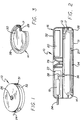
- Figure 1 is a perspective view of an implantable medication infusion pump adapted to include a liquid-vapour pressure reservoir in in accordance with the invention;
- Figure 2 is an enlarged vertical section of the pump of Figure 1,
- Figure 3 is a fragmentary perspective view showing a preferred liquid-vapour pressure reservoir construction;
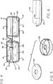
- Figure 4 is an enlarged vertical section similar to Figure 2, showing an infusion pump with a liquid-vapour pressure reservoir of an alternative preferred geometry;
- Figure 5 is an exploded perspective view illustrating the assembly of the reservoir of Figure 4;
- Figure 6 is an enlarged fragmentary vertical section of a portion of the pressure reservoir of Figure 4, illustrating operation of the reservoir during pump operation to deliver medication to a patient;
- Figure 7 is a top plan view of another alternative preferred form of the liquid-vapour pressure reservoir in accordance with the present invention;
- Figure 8 is an enlarged transverse vertical section taken generally on the line 8-8 of Figure 7;
- Figure 9 is a top plan view of an infusion pump adapted for use with the pressure reservoir of Figures 7 and 8, with an upper portion of the pump housing removed to illustrate the arrangement of pump components; and
- Figure 10 is an enlarged vertical section taken generally on the line 10-10 of Figure 9.
- As shown in the exemplary drawings, an implantable medication infusion pump referred to generally in Figures 1 and 2 by reference to
numeral 10 is provided for use in administering a selected medication to a patient in a controlled, preprogrammed manner. Theinfusion pump 10 receives and stores a quantity of the selected medication within an internal medication chamber 12 (Figure 2), wherein the medication is subjected to predetermined and substantially constant pressure through the use of an improved andsimplified reservoir 14. - The illustrative
medication infusion pump 10 comprises a small and substantially self-contained unit for direct implantation into the body of a patient. Thepump 10 comprises a hermetically sealedpump housing 16 made from a biocompatible material such as titanium or titanium alloy. Thepump housing 16 defines theinternal medication chamber 12 for receiving and storing the supply of the selectedmedication 17 in liquid form, such as insulin for a diabetic patient. Thepump housing 16 further encases aminiature dispensing pump 18 and associatedelectronic control circuitry 20 in combination with abattery 22 for periodically operating thepump 18 to deliver medication via anappropriate catheter 24 or the like. - The control circuitry is suitably preprogrammed to deliver the medication in accordance with individual patient need. An inlet or refill fitting 26 on the
pump housing 16 is adapted to receive a hypodermic needle (not shown) to permit percutaneous refilling of themedication chamber 12 without requiring surgical access to theinfusion pump 10. For a more detailed description of the overall pumps of this general type, see US Patent Nos. 4373527, and 4573994, both of which are hereby incorporated herein by reference. - The
infusion pump 10 includes the variablevolume pressure reservoir 14 mounted within thepump housing 16 with at least one wall of thepressure reservoir 14 exposed to an thereby defining at least a portion of themedication chamber 12. More particularly, thepressure reservoir 14 contains a selectedpressure medication chamber 12 in accordance with the quantity of medication therein to maintain the medication under substantially constant pressure conditions. A preferred pressure fluid comprises a fluorocarbon which has a substantially linear pressure characteristic as it changes from liquid to vapour state and vice versa at normal human body temperature and at a normal range of altitudes. A preferred pressure fluid is Freon 113 which assumes a liquid-vapour state at normal body temperature and at altitude variations up to about 8,500 feet (25.91m) above sea level to exert a slightly negative and substantially constant pressure of approximately -2.5 (1.76kg/mm²) to -4.0 psi (2.81kg/mm²) on themedication chamber 12. - This slight negative pressure beneficially confines the medication against undesired leakage from the
pump housing 16 into the body of the patient in the event of a crack or other damage to thepump housing 16. Alternatively, other liquid-vapour pressure fluids are known in the art for applying other specific pressures to the medication, such as a positive pressure which may be required for some implantable pump design. Such an application will be discussed below. - In any event, in accordance with the primary aspect of the present invention, the
pressure reservoir 14 has a simplified and improved construction for achieving significant reductions in the pump complexity and cost, as well as significant improvements in pump reliability. In addition, the improved pressure reservoir provided by the present invention permits theimplantable pump 10 to have an increased medication-containing capacity without increasing pump size, or alternatively to have a decreased overall size without reducing pump medication-containing capacity. - More specifically, with reference to Figures 2 and 3, the
pressure reservoir 14 comprises a flexible and expansible sack orbag 28 shown with a generally disc-shaped configuration and defined bycircular sheets flexible bag 28 is formed as a structural unit separate from the remaining components of theinfusion pump 10, and is desirably filled with thepressure fluid 27 prior to thebag 28 being located in thepump housing 16. - A preferred material used to construct the
bag 28 is ethylene-chlorotrifluoroethylene copolymer (ECTFE), which is sold under the name HALAR by Ausimont USA of Morristown, New Jersey. In this regard, Halar film is especially suited for use in the environment of implantable infusion pumps due to its relatively high compatibility with and impermeability to fluorocarbon pressure fluids, such as Freon 113, as well as to its compatibility with and impermeability to medications. - The
pressure reservoir 14 constructed in this way comprises a flexible yet self-contained structural unit adapted for relatively simple and cost-efficient mounting into thepump housing 16, such as by placement into a lower shall-shapedhousing half 31 prior to assembly of thelower half 31 with an upper shell-shapedhousing half 32 having thepump 18, thecircuitry 20 and thebattery 22 installed therein. An adhesive 34 may be used to seat and retain thelower sheet 29 of thebag 28 against thelower housing half 31, such that the opposite orupper sheet 30 of the bag defines a movable wall at one side of themedication chamber 12. Short spacer posts 36 may be provided around anintake port 38 leading to theminiature pump 18 to prevent any portion of thebag 28 from obstructing medication flow from thechamber 12 to the pump for administration to the patient. - In operation, the liquid-vapour pressure fluid within the
pressure reservoir 14 expands and contracts the reservoir volume in a manner inversely varying the volume of themedication chamber 12. In particular, as themedication chamber 12 is filled with medication, the pressure fluid undergoes the appropriate change of state to the liquid phase to the extent necessary to accommodate the medication yet maintain the medication under a substantially constant pressure. As the medication is dispensed to the patient in individual doses, the pressure fluid undergoes a gradual state change to the vapour phase with a corresponding expansion of the pressure reservoir sufficient to maintain the remaining medication in thechamber 12 under a substantially constant pressure. - An alternative preferred form of the invention is shown in Figures 4 to 6, in which a modified
pressure reservoir 114 is provided to maintain themedication 17 within theinfusion pump 10 under substantially constant pressure conditions. In this embodiment, thepressure reservoir 114 is constructed from a relatively more rigidlower base disc 129 formed by moulding to have a generally annular shape and upturned circular margins at its inner and outer edges. These circular margins are secured by heat sealing or the like to the inner and outer edges of an upperflexible diaphragm 130 of annular shape so that thebase disc 129 and thediaphragm 130 together define a hollow annular interior for receiving and storing a selected quantity of thepressure fluid 27. Alternatively, if desired, thebase disc 129 and the attacheddiaphragm 130 may be formed in a circular or any other selected shape. - The
reservoir 114 of Figures 4 to 6 is adapted for filling with the pressure fluid before installation into the pump housing, in generally the same manner and sequence as described with respect to Figures 2 and 3. When installed, thebase disc 129 can be seated quickly and easily into alower housing half 31 by means of an adhesive and/or by a mating snap or press fit mounting. The preferred material used to form thebase disc 129 and thediaphragm 130 again comprises a Halar film or some other material having similar properties suitable for use with the selected pressure fluid. In use, thediaphragm 130 is displaced back and forth as theadjacent medication chamber 12 is filled and emptied, as shown in Figure 6, so that the medication within thechamber 12 is maintained under substantially constant pressure. - The embodiment of Figures 4 to 6 could easily be varied to exclude the
base disc 129, and use the bottom of thelower housing half 31 instead. In this case, thediaphragm 130 would be attached, typically by the use of adhesive, directly to the sides of thelower housing half 31. - Figures 7 to 10 show another preferred embodiment of the invention, in which a
pressure reservoir 214 is formed as a flexible bag or sack 228 with a generally semicircular shape. In this version of the invention, similarly to the embodiment of Figures 2 and 3, theflexible bag 228 is preferably formed from interconnected sheets of Halar film or the like and is adapted to be filled with the selectedpressure fluid 27 before installation into a modifiedpump housing 216. As shown in Figures 9 and 10, theflexible bag 228 is mounted as a structural unit into a generallysemicircular chamber 40 at one side of thehousing 216 which has generally circular disc shape. With this geometry, thepump housing 216 co-operates with one side of thebag 228 to define asemicircular medication chamber 212. - A centrally positioned inlet fitting 226 on the
pump housing 216 permits themedication chamber 212 to be filled with the selectedmedication 17, and a dispensingpump 218 is provided for delivering the medication in doses from thechamber 212 to the patient. Thepump 218 is controlled by miniature control circuitry and a battery power source referred to generally in Figures 9 and 10 by thereference numeral 41 and positioned in another generallysemicircular chamber 42 disposed opposite to thereservoir 214. - The pump configuration shown in Figures 9 and 10 thus includes the
reservoir 214 and the associatedmedication chamber 212 in a noncircular shape, in contrast with the traditional circular shape, reservoirs and chambers defined in the art through the use of metal bellows devices. Moreover, thereservoir 214 and themedication chamber 212 are generally disposed in a common plane with the other main components of the infusion pump. This arrangement provides a substantial optimisation of the available pump housing interior volume and thereby permits the overall pump size to be significantly reduced without sacrificing medication-containing capacity. Alternatively, the volumetric capacity of themedication chamber 212 can be significantly increased relative to prior pumps of similar size. - As mentioned above, the flexible bag type pressure reservoir could also be used with a positive pressure pump. Such pumps maintain fluid in a medication chamber at a positive pressure ranging up to, for example, 10 psi (7kg/mm²). Referring again to Figure 2, a positive pressure pump could have the
medication chamber 12, thepressure reservoir 14, the inlet or refill fitting 26 as shown in Figure 1. - However, such positive pressure pumps in their simplest form include only a flow restrictor between the reservoir and the catheter. In such a pump,
reference numeral 18 in Figure 1 would refer to a flow restrictor, which is typically a capillary tube. In addition, such simple pumps do not have thecircuitry 20 and thebattery 22 installed therein. - A slightly more complex positive pressure pump would have a valve (not shown) in series with the flow restrictor, all at
reference numeral 18. This type of pump would have thecircuitry 20 and thebattery 22 installed therein, and could be externally controlled. This type of pump would operate at a fixed flow rate whenever the valve was open. - A still more complex positive pressure pump would use two valves with an accumulator therebetween, as well as the
circuitry 20 and thebattery 22. This type of pump would be externally controlled by opening first the valve between the medication reservoir and the accumulator to fill the accumulator. This valve would be closed, and the valve between the accumulator and the catheter would be opened to allow the accumulator to pump out the accumulated medication.
Claims (12)
- A medication infusion device (10) comprising: a housing (16) including a medication chamber (12) for receiving a supply of a selected medication (17); delivering means (18) within the housing (16) for delivering the medication (17) from the medication chamber (12) to a patient; and a pressure reservoir (14) containing a selected liquid-vapour pressure fluid (27), the pressure reservoir (14) being located within the housing (16) and defining a movable wall exposed to the medication chamber (12), the pressure fluid (17) being adapted to undergo sufficient liquid-vapour phase change to vary the volumetric size of the pressure reservoir (14) in response to the quantity of the medication (17) within the medication chamber (12) to maintain the medication (17) under a predetermined and substantially constant pressure.
- A device as claimed in Claim 1, characterised in that the housing (16) is hermetically sealed to permit direct implantation into the body of the patient.
- A device as claimed in Claim 1 or Claim 2, characterised in that the movable wall of the pressure reservoir (14) is formed from a flexible, impermeable, medication and pressure fluid compatible material.
- A device as claimed in any preceding Claim, characterised in that the pressure reservoir (14) is an expansible structural enclosure, preferably in the form of a bag.
- A device as claimed in Claim 4, characterised in that the pressure reservoir (14) is an expansible bag comprising a pair of plastic film sheets (29,30) interconnected about the peripheries to define a hollow bag (28) interior for receiving the pressure fluid (17).
- A device as claimed in Claim 4, characterised in that the pressure reservoir (14) comprises a pillow-shaped member (214) having two sides made of a flexible material sealed about their periphery to enclose the selected liquid-vapour pressure fluid (17).
- A device as claimed in any preceding Claim, characterised in that the movable wall and/or the structural enclosure (14) is formed from Halar film material.
- A device as claimed in any preceding Claim, characterised in that the delivery means includes an intake port (38) in communication with the medication chamber (12), and means for preventing the pressure reservoir from obstructing the intake port (38).
- A device as claimed in any preceding Claim, characterised in that the pressure fluid (17) is selected to maintain the medication chamber under a pressure less than atmospheric pressure , and the delivery means comprises a pump (18).
- A device as claimed in any preceding Claim, characterised in that the pressure fluid (17) comprises a fluorocarbon, preferably Freon 113.
- A device as claimed in any of Claims 1 to 8, characterised in that the pressure fluid (17) is selected to maintain the medication chamber (12) under a pressure greater than atmospheric pressure.
- A device as claimed in any preceding Claim, characterised by means (34) for securing the pressure reservoir within the housing (16).
Applications Claiming Priority (2)
| Application Number | Priority Date | Filing Date | Title |
|---|---|---|---|
| US07/619,650 US5167633A (en) | 1990-11-29 | 1990-11-29 | Liquid-vapor pressure reservoir for medication infusion pump |
| US619650 | 1990-11-29 |
Publications (2)
| Publication Number | Publication Date |
|---|---|
| EP0488701A1 true EP0488701A1 (en) | 1992-06-03 |
| EP0488701B1 EP0488701B1 (en) | 1996-02-14 |
Family
ID=24482765
Family Applications (1)
| Application Number | Title | Priority Date | Filing Date |
|---|---|---|---|
| EP91310976A Expired - Lifetime EP0488701B1 (en) | 1990-11-29 | 1991-11-28 | Liquid-vapour pressure reservoir for medication infusion pump |
Country Status (5)
| Country | Link |
|---|---|
| US (1) | US5167633A (en) |
| EP (1) | EP0488701B1 (en) |
| JP (1) | JP3127020B2 (en) |
| CA (1) | CA2054148C (en) |
| DE (1) | DE69117147T2 (en) |
Cited By (7)
| Publication number | Priority date | Publication date | Assignee | Title |
|---|---|---|---|---|
| WO1995004571A1 (en) * | 1993-08-11 | 1995-02-16 | Thomas John Berrigan | Implantable drug delivery means |
| WO1996000050A1 (en) * | 1994-06-23 | 1996-01-04 | R.P. Scherer Corporation | Ocular treatment device |
| WO2000048652A1 (en) * | 1999-02-19 | 2000-08-24 | Medical Research Group, Inc. | Negative pressure infusion pump |
| US6280416B1 (en) | 1999-02-19 | 2001-08-28 | Minimed Inc. | Constant flow medication infusion pump |
| US6319245B1 (en) | 1996-10-09 | 2001-11-20 | Thomas John Berrigan | Drug delivery means |
| WO2012098468A3 (en) * | 2011-01-21 | 2012-10-26 | Palyon Medical (Bvi) Limited | Reduced sized programmable implantable pump |
| WO2017027791A1 (en) * | 2015-08-13 | 2017-02-16 | Medtronic, Inc. | Leak reduction during implantable infusion device refill |
Families Citing this family (71)
| Publication number | Priority date | Publication date | Assignee | Title |
|---|---|---|---|---|
| US6358239B1 (en) | 1992-01-24 | 2002-03-19 | I-Flow Corporation | Platen pump |
| US6251098B1 (en) * | 1992-01-24 | 2001-06-26 | I-Flow, Corp. | Fluid container for use with platen pump |
| US5411482A (en) * | 1992-11-02 | 1995-05-02 | Infusion Technologies Corporation | Valve system and method for control of an infusion pump |
| US5514103A (en) | 1994-06-14 | 1996-05-07 | Minimed Inc. | Medication infusion pump with improved pressure reservoir |
| DE4432991C1 (en) * | 1994-09-16 | 1995-10-26 | Fresenius Ag | Infusion pump for dispensing medicines into human body |
| DE19509634C1 (en) * | 1995-03-17 | 1996-03-28 | Fresenius Ag | Implantable infusion pump with constant delivery rate |
| DE19517291C2 (en) * | 1995-05-11 | 1997-05-15 | Fresenius Ag | Method for filling a propellant space of a gas pressure-operated medication pump and gas pressure-operated medication pump |
| BR9600722A (en) * | 1996-02-14 | 1997-12-30 | Jorge Antonio Rodrigues Claro | Infusion pump for contained in flexible plastic bags |
| US8177762B2 (en) | 1998-12-07 | 2012-05-15 | C. R. Bard, Inc. | Septum including at least one identifiable feature, access ports including same, and related methods |
| US6764472B1 (en) | 2000-01-11 | 2004-07-20 | Bard Access Systems, Inc. | Implantable refillable infusion device |
| US6770067B2 (en) | 2001-09-07 | 2004-08-03 | Medtronic Minimed, Inc. | Infusion device and driving mechanism for same |
| US6652510B2 (en) | 2001-09-07 | 2003-11-25 | Medtronic Minimed, Inc. | Implantable infusion device and reservoir for same |
| US6997921B2 (en) | 2001-09-07 | 2006-02-14 | Medtronic Minimed, Inc. | Infusion device and driving mechanism for same |
| US7186236B2 (en) * | 2001-09-07 | 2007-03-06 | Medtronic Minimed, Inc. | Infusion device and inlet structure for same |
| US20090118711A1 (en) * | 2001-09-07 | 2009-05-07 | Medtronic, Inc. | Reduced-noise implantable infusion device |
| US7452354B2 (en) * | 2002-06-26 | 2008-11-18 | Inset Technologies Incorporated | Implantable pump connector for catheter attachment |
| US7255690B2 (en) * | 2002-12-26 | 2007-08-14 | Medtronic Minimed, Inc. | Infusion device having piston operated driving mechanism and positive pressure reservoir |
| US6932584B2 (en) * | 2002-12-26 | 2005-08-23 | Medtronic Minimed, Inc. | Infusion device and driving mechanism and process for same with actuator for multiple infusion uses |
| US7351240B2 (en) * | 2004-05-28 | 2008-04-01 | Ethicon Endo—Srugery, Inc. | Thermodynamically driven reversible infuser pump for use as a remotely controlled gastric band |
| JP4656909B2 (en) * | 2004-10-15 | 2011-03-23 | オリンパス株式会社 | Intra-subject introduction apparatus and method for manufacturing the same |
| US7785302B2 (en) | 2005-03-04 | 2010-08-31 | C. R. Bard, Inc. | Access port identification systems and methods |
| US9474888B2 (en) | 2005-03-04 | 2016-10-25 | C. R. Bard, Inc. | Implantable access port including a sandwiched radiopaque insert |
| US7947022B2 (en) * | 2005-03-04 | 2011-05-24 | C. R. Bard, Inc. | Access port identification systems and methods |
| US8029482B2 (en) | 2005-03-04 | 2011-10-04 | C. R. Bard, Inc. | Systems and methods for radiographically identifying an access port |
| EP3173121B8 (en) | 2005-04-27 | 2021-03-24 | C.R. Bard Inc. | Infusion apparatuses provided with septum |
| WO2006116613A1 (en) | 2005-04-27 | 2006-11-02 | C.R. Bard, Inc. | Infusion apparatuses |
| US10307581B2 (en) | 2005-04-27 | 2019-06-04 | C. R. Bard, Inc. | Reinforced septum for an implantable medical device |
| US8034029B2 (en) * | 2005-05-25 | 2011-10-11 | Palyon Medical (Bvi) Limited | Multi-reservoir implantable pump with patient controlled actuation |
| US7753660B2 (en) * | 2005-10-18 | 2010-07-13 | Medtronic Minimed, Inc. | Infusion device and actuator for same |
| US7708730B2 (en) | 2006-01-30 | 2010-05-04 | Palyon Medical (Bvi) Limited | Template system for multi-reservoir implantable pump |
| EP1839695A1 (en) * | 2006-03-31 | 2007-10-03 | Debiotech S.A. | Medical liquid injection device |
| US9265912B2 (en) | 2006-11-08 | 2016-02-23 | C. R. Bard, Inc. | Indicia informative of characteristics of insertable medical devices |
| US9642986B2 (en) | 2006-11-08 | 2017-05-09 | C. R. Bard, Inc. | Resource information key for an insertable medical device |
| US7798789B2 (en) * | 2007-05-16 | 2010-09-21 | Medtronic, Inc. | Reducing cylinder wear in a drug pump |
| US20080287874A1 (en) * | 2007-05-18 | 2008-11-20 | Medtronic, Inc. | Controlling dead volume of a piston pump using an adjustment screw |
| US20080312595A1 (en) * | 2007-06-12 | 2008-12-18 | Medtronic, Inc. | Articulated actuator for implantable pump |
| EP3269417A1 (en) | 2007-06-20 | 2018-01-17 | Medical Components, Inc. | Implantable access port with molded and/or radiopaque indicia |
| EP3311877A1 (en) | 2007-07-19 | 2018-04-25 | Medical Components, Inc. | Venous access port assembly with x-ray discernable indicia |
| WO2009012395A1 (en) | 2007-07-19 | 2009-01-22 | Innovative Medical Devices, Llc | Venous access port assembly with x-ray discernable indicia |
| JP5244815B2 (en) * | 2007-10-31 | 2013-07-24 | オリンパス株式会社 | Chemical solution administration system |
| US9579496B2 (en) | 2007-11-07 | 2017-02-28 | C. R. Bard, Inc. | Radiopaque and septum-based indicators for a multi-lumen implantable port |
| US8105269B2 (en) | 2008-10-24 | 2012-01-31 | Baxter International Inc. | In situ tubing measurements for infusion pumps |
| US20100106097A1 (en) * | 2008-10-29 | 2010-04-29 | Medtronic, Inc. | Drug acceptability indicator |
| MX337695B (en) | 2008-10-31 | 2016-03-15 | Bard Inc C R | Systems and methods for identifying an acess port. |
| US8932271B2 (en) | 2008-11-13 | 2015-01-13 | C. R. Bard, Inc. | Implantable medical devices including septum-based indicators |
| US11890443B2 (en) | 2008-11-13 | 2024-02-06 | C. R. Bard, Inc. | Implantable medical devices including septum-based indicators |
| US9968733B2 (en) * | 2008-12-15 | 2018-05-15 | Medtronic, Inc. | Air tolerant implantable piston pump |
| US9250106B2 (en) | 2009-02-27 | 2016-02-02 | Tandem Diabetes Care, Inc. | Methods and devices for determination of flow reservoir volume |
| WO2010099490A2 (en) | 2009-02-27 | 2010-09-02 | Tandem Diabetes Care, Inc. | Methods and devices for determination of flow reservoir volume |
| US8137083B2 (en) | 2009-03-11 | 2012-03-20 | Baxter International Inc. | Infusion pump actuators, system and method for controlling medical fluid flowrate |
| US20100274195A1 (en) * | 2009-04-23 | 2010-10-28 | Medtronic, Inc. | Implantable Device Suture Bars |
| US20100280531A1 (en) * | 2009-04-30 | 2010-11-04 | Medtronic, Inc. | Snap-on suture ring for implantable medical device |
| EP2451512A1 (en) | 2009-07-07 | 2012-05-16 | C.R. Bard Inc. | Extensible internal bolster for a medical device |
| EP3284494A1 (en) | 2009-07-30 | 2018-02-21 | Tandem Diabetes Care, Inc. | Portable infusion pump system |
| EP2501294B1 (en) | 2009-11-17 | 2018-08-15 | C.R. Bard, Inc. | Overmolded access port including anchoring and identification features |
| US8382447B2 (en) | 2009-12-31 | 2013-02-26 | Baxter International, Inc. | Shuttle pump with controlled geometry |
| US8567235B2 (en) | 2010-06-29 | 2013-10-29 | Baxter International Inc. | Tube measurement technique using linear actuator and pressure sensor |
| USD676955S1 (en) | 2010-12-30 | 2013-02-26 | C. R. Bard, Inc. | Implantable access port |
| USD682416S1 (en) | 2010-12-30 | 2013-05-14 | C. R. Bard, Inc. | Implantable access port |
| US8591456B2 (en) | 2011-12-28 | 2013-11-26 | Palyon Medical (Bvi) Limited | Multiple reservoir programmable pump |
| US9180242B2 (en) | 2012-05-17 | 2015-11-10 | Tandem Diabetes Care, Inc. | Methods and devices for multiple fluid transfer |
| US11420033B2 (en) | 2013-01-23 | 2022-08-23 | C. R. Bard, Inc. | Low-profile single and dual vascular access device |
| EP3342391A1 (en) | 2013-01-23 | 2018-07-04 | C.R. Bard Inc. | Low-profile access port |
| US11464960B2 (en) | 2013-01-23 | 2022-10-11 | C. R. Bard, Inc. | Low-profile single and dual vascular access device |
| US9173998B2 (en) | 2013-03-14 | 2015-11-03 | Tandem Diabetes Care, Inc. | System and method for detecting occlusions in an infusion pump |
| US9603995B2 (en) | 2013-03-15 | 2017-03-28 | Tandem Diabetes Care. Inc. | Device and method for setting therapeutic parameters for an infusion device |
| JP2016105748A (en) * | 2013-04-02 | 2016-06-16 | テルモ株式会社 | Medical solution container and medical solution administration device |
| KR101580806B1 (en) * | 2013-10-29 | 2015-12-29 | 진화메디칼 주식회사 | Liqid Chemical Feeder |
| NL2015004B1 (en) * | 2015-06-19 | 2017-01-24 | Ipadic B V | Implantable infusion system. |
| JP2015227664A (en) * | 2015-09-03 | 2015-12-17 | セイコーエプソン株式会社 | Fluid transportation device and cartridge |
| USD870264S1 (en) | 2017-09-06 | 2019-12-17 | C. R. Bard, Inc. | Implantable apheresis port |
Citations (4)
| Publication number | Priority date | Publication date | Assignee | Title |
|---|---|---|---|---|
| WO1983002063A1 (en) * | 1981-12-07 | 1983-06-23 | Univ Johns Hopkins | Refillable medication infusion apparatus |
| EP0272530A2 (en) * | 1986-12-18 | 1988-06-29 | F. Hoffmann-La Roche Ag | Device for applying fluid substances |
| US4857055A (en) * | 1986-04-15 | 1989-08-15 | Wang Paul Y | Compression device enabling flexible solution containers to produce constant delivery rate |
| EP0347743A2 (en) * | 1988-06-23 | 1989-12-27 | Fresenius AG | Septum for implantable devices releasing agents |
Family Cites Families (11)
| Publication number | Priority date | Publication date | Assignee | Title |
|---|---|---|---|---|
| US3840009A (en) * | 1971-12-27 | 1974-10-08 | Alza Corp | Self-powered vapor pressure delivery device |
| US3951147A (en) * | 1975-04-07 | 1976-04-20 | Metal Bellows Company | Implantable infusate pump |
| US4619653A (en) * | 1979-04-27 | 1986-10-28 | The Johns Hopkins University | Apparatus for detecting at least one predetermined condition and providing an informational signal in response thereto in a medication infusion system |
| US4525165A (en) * | 1979-04-27 | 1985-06-25 | The Johns Hopkins University | Fluid handling system for medication infusion system |
| US4525164A (en) * | 1981-04-24 | 1985-06-25 | Biotek, Inc. | Wearable medication infusion system with arcuated reservoir |
| US4552561A (en) * | 1982-12-23 | 1985-11-12 | Alza Corporation | Body mounted pump housing and pump assembly employing the same |
| US4581018A (en) * | 1983-02-08 | 1986-04-08 | Novacor Medical Corporation | Implantable infusion device |
| US4655765A (en) * | 1984-06-01 | 1987-04-07 | Parker Hannifin Corporation | Fitting with prestressed septum |
| CA1254091A (en) * | 1984-09-28 | 1989-05-16 | Vladimir Feingold | Implantable medication infusion system |
| US4626244A (en) * | 1985-02-01 | 1986-12-02 | Consolidated Controls Corporation | Implantable medication infusion device |
| FR2582222A1 (en) * | 1985-05-21 | 1986-11-28 | Applied Precision Ltd | IMPLANTABLE MANUAL ACTION DEVICE FOR THE SEQUENTIAL DELIVERY OF DOSES OF A SUBSTANCE, ESPECIALLY THERAPEUTIC |
-
1990
- 1990-11-29 US US07/619,650 patent/US5167633A/en not_active Expired - Lifetime
-
1991
- 1991-10-24 CA CA002054148A patent/CA2054148C/en not_active Expired - Fee Related
- 1991-11-28 DE DE69117147T patent/DE69117147T2/en not_active Expired - Fee Related
- 1991-11-28 EP EP91310976A patent/EP0488701B1/en not_active Expired - Lifetime
- 1991-11-29 JP JP03316413A patent/JP3127020B2/en not_active Expired - Fee Related
Patent Citations (4)
| Publication number | Priority date | Publication date | Assignee | Title |
|---|---|---|---|---|
| WO1983002063A1 (en) * | 1981-12-07 | 1983-06-23 | Univ Johns Hopkins | Refillable medication infusion apparatus |
| US4857055A (en) * | 1986-04-15 | 1989-08-15 | Wang Paul Y | Compression device enabling flexible solution containers to produce constant delivery rate |
| EP0272530A2 (en) * | 1986-12-18 | 1988-06-29 | F. Hoffmann-La Roche Ag | Device for applying fluid substances |
| EP0347743A2 (en) * | 1988-06-23 | 1989-12-27 | Fresenius AG | Septum for implantable devices releasing agents |
Cited By (13)
| Publication number | Priority date | Publication date | Assignee | Title |
|---|---|---|---|---|
| WO1995004571A1 (en) * | 1993-08-11 | 1995-02-16 | Thomas John Berrigan | Implantable drug delivery means |
| US5871478A (en) * | 1993-08-11 | 1999-02-16 | Berrigan; Thomas John | Implantable drug delivery means |
| US7018375B2 (en) | 1993-08-11 | 2006-03-28 | Thomas John Berrigan | Drug delivery device |
| US6471686B1 (en) | 1993-08-11 | 2002-10-29 | Thomas John Berrigan | Drug delivery device |
| WO1996000050A1 (en) * | 1994-06-23 | 1996-01-04 | R.P. Scherer Corporation | Ocular treatment device |
| US6319245B1 (en) | 1996-10-09 | 2001-11-20 | Thomas John Berrigan | Drug delivery means |
| US6283943B1 (en) | 1999-02-19 | 2001-09-04 | Minimed Inc. | Negative pressure pump |
| US6280416B1 (en) | 1999-02-19 | 2001-08-28 | Minimed Inc. | Constant flow medication infusion pump |
| EP1510230A1 (en) * | 1999-02-19 | 2005-03-02 | Medical Research Group, Inc. | Negative pressure medical infusion pump |
| WO2000048652A1 (en) * | 1999-02-19 | 2000-08-24 | Medical Research Group, Inc. | Negative pressure infusion pump |
| WO2012098468A3 (en) * | 2011-01-21 | 2012-10-26 | Palyon Medical (Bvi) Limited | Reduced sized programmable implantable pump |
| WO2017027791A1 (en) * | 2015-08-13 | 2017-02-16 | Medtronic, Inc. | Leak reduction during implantable infusion device refill |
| US10525247B2 (en) | 2015-08-13 | 2020-01-07 | Medtronic, Inc. | Leak reduction during implantable infusion device refill |
Also Published As
| Publication number | Publication date |
|---|---|
| CA2054148A1 (en) | 1992-05-30 |
| US5167633A (en) | 1992-12-01 |
| EP0488701B1 (en) | 1996-02-14 |
| DE69117147T2 (en) | 1996-07-04 |
| DE69117147D1 (en) | 1996-03-28 |
| CA2054148C (en) | 1995-11-28 |
| JP3127020B2 (en) | 2001-01-22 |
| JPH04272770A (en) | 1992-09-29 |
Similar Documents
| Publication | Publication Date | Title |
|---|---|---|
| EP0488701B1 (en) | Liquid-vapour pressure reservoir for medication infusion pump | |
| US5176644A (en) | Medication infusion pump with improved liquid-vapor pressure reservoir | |
| EP0687475B1 (en) | Medical infusion pump with improved pressure reservoir | |
| EP0998317B1 (en) | Inlet port for a medication infusion pump | |
| US5176641A (en) | Implantable drug infusion reservoir having fluid impelling resilient foam member | |
| US5607418A (en) | Implantable drug delivery apparatus | |
| US4838887A (en) | Programmable valve pump | |
| US5197322A (en) | Pressure reservoir filling process for an implantable medication infusion pump | |
| US5725017A (en) | In-line pressure check valve for drug-delivery systems | |
| US5551849A (en) | Medication delivery device and method of construction | |
| EP1087807B1 (en) | Medical infusion device with a source of controlled compliance | |
| US5049141A (en) | Programmable valve pump | |
| US5053031A (en) | Pump infusion system | |
| EP0162082B1 (en) | Implantable infusion device | |
| US8425493B2 (en) | Implantable medication delivery device | |
| US20030050623A1 (en) | Implantable infusion device and reservoir for same | |
| EP0291612B1 (en) | Implantable pump. | |
| JPH0151268B2 (en) | ||
| EP0335671A1 (en) | Implantable drug delivery system |
Legal Events
| Date | Code | Title | Description |
|---|---|---|---|
| PUAI | Public reference made under article 153(3) epc to a published international application that has entered the european phase |
Free format text: ORIGINAL CODE: 0009012 |
|
| AK | Designated contracting states |
Kind code of ref document: A1 Designated state(s): DE FR GB IT NL SE |
|
| 17P | Request for examination filed |
Effective date: 19921119 |
|
| 17Q | First examination report despatched |
Effective date: 19940628 |
|
| RAP1 | Party data changed (applicant data changed or rights of an application transferred) |
Owner name: MINIMED INC., DOING BUSINESS AS MINIMED TECHNOLOGI |
|
| ITF | It: translation for a ep patent filed |
Owner name: BARZANO' E ZANARDO ROMA S.P.A. |
|
| GRAA | (expected) grant |
Free format text: ORIGINAL CODE: 0009210 |
|
| AK | Designated contracting states |
Kind code of ref document: B1 Designated state(s): DE FR GB IT NL SE |
|
| PG25 | Lapsed in a contracting state [announced via postgrant information from national office to epo] |
Ref country code: NL Free format text: LAPSE BECAUSE OF FAILURE TO SUBMIT A TRANSLATION OF THE DESCRIPTION OR TO PAY THE FEE WITHIN THE PRESCRIBED TIME-LIMIT Effective date: 19960214 |
|
| REF | Corresponds to: |
Ref document number: 69117147 Country of ref document: DE Date of ref document: 19960328 |
|
| ET | Fr: translation filed | ||
| PG25 | Lapsed in a contracting state [announced via postgrant information from national office to epo] |
Ref country code: SE Effective date: 19960514 |
|
| NLV1 | Nl: lapsed or annulled due to failure to fulfill the requirements of art. 29p and 29m of the patents act | ||
| PLBE | No opposition filed within time limit |
Free format text: ORIGINAL CODE: 0009261 |
|
| STAA | Information on the status of an ep patent application or granted ep patent |
Free format text: STATUS: NO OPPOSITION FILED WITHIN TIME LIMIT |
|
| 26N | No opposition filed | ||
| REG | Reference to a national code |
Ref country code: GB Ref legal event code: IF02 |
|
| PG25 | Lapsed in a contracting state [announced via postgrant information from national office to epo] |
Ref country code: IT Free format text: LAPSE BECAUSE OF NON-PAYMENT OF DUE FEES;WARNING: LAPSES OF ITALIAN PATENTS WITH EFFECTIVE DATE BEFORE 2007 MAY HAVE OCCURRED AT ANY TIME BEFORE 2007. THE CORRECT EFFECTIVE DATE MAY BE DIFFERENT FROM THE ONE RECORDED. Effective date: 20051128 |
|
| PGFP | Annual fee paid to national office [announced via postgrant information from national office to epo] |
Ref country code: FR Payment date: 20081106 Year of fee payment: 18 |
|
| PGFP | Annual fee paid to national office [announced via postgrant information from national office to epo] |
Ref country code: DE Payment date: 20081128 Year of fee payment: 18 |
|
| PGFP | Annual fee paid to national office [announced via postgrant information from national office to epo] |
Ref country code: GB Payment date: 20081008 Year of fee payment: 18 |
|
| GBPC | Gb: european patent ceased through non-payment of renewal fee |
Effective date: 20091128 |
|
| REG | Reference to a national code |
Ref country code: FR Ref legal event code: ST Effective date: 20100730 |
|
| PG25 | Lapsed in a contracting state [announced via postgrant information from national office to epo] |
Ref country code: FR Free format text: LAPSE BECAUSE OF NON-PAYMENT OF DUE FEES Effective date: 20091130 |
|
| PG25 | Lapsed in a contracting state [announced via postgrant information from national office to epo] |
Ref country code: DE Free format text: LAPSE BECAUSE OF NON-PAYMENT OF DUE FEES Effective date: 20100601 |
|
| PG25 | Lapsed in a contracting state [announced via postgrant information from national office to epo] |
Ref country code: GB Free format text: LAPSE BECAUSE OF NON-PAYMENT OF DUE FEES Effective date: 20091128 |