EP0488494A1 - Power latch system - Google Patents
Power latch system Download PDFInfo
- Publication number
- EP0488494A1 EP0488494A1 EP91306311A EP91306311A EP0488494A1 EP 0488494 A1 EP0488494 A1 EP 0488494A1 EP 91306311 A EP91306311 A EP 91306311A EP 91306311 A EP91306311 A EP 91306311A EP 0488494 A1 EP0488494 A1 EP 0488494A1
- Authority
- EP
- European Patent Office
- Prior art keywords
- latch
- convertible top
- rotating element
- nut
- coupled
- Prior art date
- Legal status (The legal status is an assumption and is not a legal conclusion. Google has not performed a legal analysis and makes no representation as to the accuracy of the status listed.)
- Withdrawn
Links
Images


Classifications
-
- B—PERFORMING OPERATIONS; TRANSPORTING
- B60—VEHICLES IN GENERAL
- B60J—WINDOWS, WINDSCREENS, NON-FIXED ROOFS, DOORS, OR SIMILAR DEVICES FOR VEHICLES; REMOVABLE EXTERNAL PROTECTIVE COVERINGS SPECIALLY ADAPTED FOR VEHICLES
- B60J7/00—Non-fixed roofs; Roofs with movable panels, e.g. rotary sunroofs
- B60J7/185—Locking arrangements
- B60J7/1851—Locking arrangements for locking the foldable soft- or hard-top to the windshield header
-
- E—FIXED CONSTRUCTIONS
- E05—LOCKS; KEYS; WINDOW OR DOOR FITTINGS; SAFES
- E05B—LOCKS; ACCESSORIES THEREFOR; HANDCUFFS
- E05B47/00—Operating or controlling locks or other fastening devices by electric or magnetic means
- E05B47/0001—Operating or controlling locks or other fastening devices by electric or magnetic means with electric actuators; Constructional features thereof
- E05B47/0012—Operating or controlling locks or other fastening devices by electric or magnetic means with electric actuators; Constructional features thereof with rotary electromotors
-
- E—FIXED CONSTRUCTIONS
- E05—LOCKS; KEYS; WINDOW OR DOOR FITTINGS; SAFES
- E05C—BOLTS OR FASTENING DEVICES FOR WINGS, SPECIALLY FOR DOORS OR WINDOWS
- E05C5/00—Fastening devices with bolts moving otherwise than only rectilinearly and only pivotally or rotatively
-
- E—FIXED CONSTRUCTIONS
- E05—LOCKS; KEYS; WINDOW OR DOOR FITTINGS; SAFES
- E05B—LOCKS; ACCESSORIES THEREFOR; HANDCUFFS
- E05B47/00—Operating or controlling locks or other fastening devices by electric or magnetic means
- E05B47/0001—Operating or controlling locks or other fastening devices by electric or magnetic means with electric actuators; Constructional features thereof
- E05B2047/0014—Constructional features of actuators or power transmissions therefor
- E05B2047/0018—Details of actuator transmissions
- E05B2047/0023—Nuts or nut-like elements moving along a driven threaded axle
-
- E—FIXED CONSTRUCTIONS
- E05—LOCKS; KEYS; WINDOW OR DOOR FITTINGS; SAFES
- E05C—BOLTS OR FASTENING DEVICES FOR WINGS, SPECIALLY FOR DOORS OR WINDOWS
- E05C19/00—Other devices specially designed for securing wings, e.g. with suction cups
- E05C19/10—Hook fastenings; Fastenings in which a link engages a fixed hook-like member
-
- Y—GENERAL TAGGING OF NEW TECHNOLOGICAL DEVELOPMENTS; GENERAL TAGGING OF CROSS-SECTIONAL TECHNOLOGIES SPANNING OVER SEVERAL SECTIONS OF THE IPC; TECHNICAL SUBJECTS COVERED BY FORMER USPC CROSS-REFERENCE ART COLLECTIONS [XRACs] AND DIGESTS
- Y10—TECHNICAL SUBJECTS COVERED BY FORMER USPC
- Y10S—TECHNICAL SUBJECTS COVERED BY FORMER USPC CROSS-REFERENCE ART COLLECTIONS [XRACs] AND DIGESTS
- Y10S292/00—Closure fasteners
- Y10S292/05—Automobile top latches
-
- Y—GENERAL TAGGING OF NEW TECHNOLOGICAL DEVELOPMENTS; GENERAL TAGGING OF CROSS-SECTIONAL TECHNOLOGIES SPANNING OVER SEVERAL SECTIONS OF THE IPC; TECHNICAL SUBJECTS COVERED BY FORMER USPC CROSS-REFERENCE ART COLLECTIONS [XRACs] AND DIGESTS
- Y10—TECHNICAL SUBJECTS COVERED BY FORMER USPC
- Y10S—TECHNICAL SUBJECTS COVERED BY FORMER USPC CROSS-REFERENCE ART COLLECTIONS [XRACs] AND DIGESTS
- Y10S292/00—Closure fasteners
- Y10S292/49—Toggle catches
-
- Y—GENERAL TAGGING OF NEW TECHNOLOGICAL DEVELOPMENTS; GENERAL TAGGING OF CROSS-SECTIONAL TECHNOLOGIES SPANNING OVER SEVERAL SECTIONS OF THE IPC; TECHNICAL SUBJECTS COVERED BY FORMER USPC CROSS-REFERENCE ART COLLECTIONS [XRACs] AND DIGESTS
- Y10—TECHNICAL SUBJECTS COVERED BY FORMER USPC
- Y10T—TECHNICAL SUBJECTS COVERED BY FORMER US CLASSIFICATION
- Y10T292/00—Closure fasteners
- Y10T292/08—Bolts
- Y10T292/0911—Hooked end
- Y10T292/0913—Sliding and swinging
- Y10T292/0914—Operating means
Definitions
- the invention relates generally to powered latching systems for effecting engagement and disengagement between two members, such as an automobile convertible top and the windshield header of the automobile.
- Latching systems are known wherein pins or dowels are mounted to a convertible top header for lowering into receiving cavities formed in the vehicle's windshield header.
- prior systems may have pins associated with the windshield header which engage cavities in the convertible header.
- problems associated with such known arrangements caused by misalignment of the pin and its receiving cavity. Such misalignment may lead to binding up of the parts rendering the latch system either inoperative or in need of expensive repair.
- the invention contemplates apparatus for effecting powered latching engagement and disengagement between relatively moveable first and second members.
- the apparatus includes reversible drive apparatus coupled to one of the first and second members, a latch element having a substantially J-shaped keeper, a latch engaging member associated with the other one of the first and second members and shaped for latching receipt of at least a portion of the J-shaped keeper, and a linkage arrangement including a drive link having a first end coupled to the drive apparatus, a rotating element coupled to a second end of the drive link and to the latch, and a cam providing a path-defining guide for the latch element, the drive link operative in cooperation with the drive apparatus to rotate the rotating element about the cam to move the latch element across the cam into and out of latching engagement with the latch engaging element.
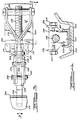
- the invention is shown as an assembly 100 mounted in the vicinity of the forwardly movable portion of a convertible top 110 which when in a closed position rests upon a region generally defined by a windshield header 112 of windshield 114.
- the apparatus arranged in accordance with the invention is situated along an articulated side rail 202 of a conventional convertible top 110, the apparatus preferably being duplicated at the other side of the car (not shown) such that a latching arrangement near opposite ends of the windshield header effects engagement and disengagement of convertible top 110 with the windshield header 112.
- Assembly 100 is arranged as a modular unit for coupling to conventional articulated side rail 202 of convertible top 110.
- This modular construction permits installation of the unit in many different vehicle models.
- the module itself includes a simple generally flat mounting base 204 which is coupled to side rail 202 via a plurality of bolts such as shown at 206 and 208 in Figure 2.
- a threaded bolt 206 is threadingly received in a longitudinal mounting boss 210 disposed on each side of the assembly, while a pair of threaded bolts 208 are threadingly received in a transverse mounting boss 212. Both bosses may be an integral part of the mounting base 204.
- the driving element of the power latch assembly comprises a reversible electric motor 214.
- Motor 214 is preferably powered by the vehicle through the usual electrical connection to an alternator or battery in a manner well-known to those skilled in the art.
- An operator actuated switch (not shown) interconnects motor 214 with the automotive source of power to render the motor selectively operative in either of two rotative directions.
- Motor 214 is coupled via a gear train 216 to a rotatable threaded spindle or shaft 218.
- gear train 216 Components of gear train 216, the main drive shaft of motor 214 and the threaded spindle 218 are all at least partially supported by transverse bosses 212 and 224, which also may be integral parts of the modular unit's mounting base 204.
- the end of spindle 218 remote from the gear train 216 is appropriately journaled in boss 222.
- Threadingly engaging the rotatable threaded spindle 218 is a threaded drive nut 220.
- Rotation of nut 220 is prevented by a projection 221 thereon which is slidably received in a longitudinally extending channel 223 affixed to base 204.
- a drive link 226 is rotatively coupled between threaded drive nut 220 and a rotating element 228.
- nut 220 is pivotally coupled to a bifurcated end of drive link 226 via two shouldered bolts 227 and 229.
- Element 228 is in turn pivotally connected via a pivot pin 246 to an upwardly open channel-shaped guide block 230 affixed to base 204 and having a pair of identical transversely aligned cams 231 on the forward edges thereof.
- Element 228 is also pivotally connected, via a shouldered pivot pin 248 and a pair of nuts 249, to latch element 232.
- Latch element 232 includes a substantially J-shaped keeper 234 which extends through an opening 250 in articulated side rail 202. Keeper 234 is shaped for latching engagement with a latch receiving flange portion 236 of an automotive windshield header 112. In conventional fashion, the convertible top header element 240 rests on a collapsible elastomeric seal assembly 242 associated with windshield header 112 in order to accommodate manufacturing tolerances and provide the necessary seal.
- Both the threaded nut 220 and the keeper 234 of latch 232 are shown in both solid and phantom positions in Figure 2.
- nut 220 is at a left-most position along threaded shaft 218 as shown at 220P in Figure 2, then the keeper 234 of latch 232 will be disposed in the fully disengaged or unlocked position shown in phantom lines at 234P.
- latching or unlatching of keeper 234 of latch 232 is effected, depending on the direction of rotation of motor 214.
- the latch includes a main body portion, indicated at 232, which on one side supports keeper 234 and on the opposite side has a pair of follower elements, each having a follower surface 233 adapted to engage one of cams 231.
- the latch body is also configured to engage both cams 231.
- motor 214 is energized to rotate shaft 218 via gear train 216 to begin movement of threaded nut 220 from a right-most position shown in solid lines in Figure 2 along shaft 218 in a direction toward the left as one views Figure 2.
- keeper 234 will begin to withdraw from flange 236 as shown in Figure 5A.
- latch element 232 initially moves in a plane almost parallel to the plane of windshield 114 ( Figure 1) to effect unlatching. This direction of movement is a result of the engagement of latch body 232 on cams 231, the upper portions of which are generally parallel to the windshield to give the desired direction of movement.
- Figure 5A it will be seen that the translating motion of nut 220 is in the direction depicted by arrow 501.
- Figure 5B shows hook element 234 further retracted from flange 236 in an intermediate portion of the travel of nut 220 along shaft 218. At the position shown in Figure 5B, follower surfaces 233 are about to engage the arcuate lower portions of cams 231.
- nut 220 is driven by motor 214 rotating shaft 218 such that nut 220 will move in the direction shown by arrow 502 of Figure 5A.
- link 226 will pull rotating element 228 in a clockwise direction to effect latching engagement of at least a portion of keeper 234 of latch 232 with the flange portion 236 of windshield header 238, with the final motion being in a direction to pull the top tightly against the header.
- one significant advantage of the cam arrangement described herein is that one can alter the shape of the cam for use of the modular power latching system with a variety of different model vehicles. Furthermore, the use of a hook-type keeper with a windshield header flange means that accurate alignment of the moving and fixed parts is not critical. This condition, in turn, eliminates the binding problems encountered in prior art arrangements when trying to automatically insert a pin or rod into a mating cavity.
Abstract
A powered latching device (100) for an automotive vehicle convertible top (110) includes a reversible drive element linked to a latch incorporating a substantially J-shaped keeper for engaging a latch receiving flange portion of the vehicle's windshield header (112). The modular latching system is mounted to an articulated side rail of the convertible top, and, preferably two such latching systems are employed, one on each side rail of the convertible top.
Description
- The invention relates generally to powered latching systems for effecting engagement and disengagement between two members, such as an automobile convertible top and the windshield header of the automobile.
- Latching systems are known wherein pins or dowels are mounted to a convertible top header for lowering into receiving cavities formed in the vehicle's windshield header. Alternatively, prior systems may have pins associated with the windshield header which engage cavities in the convertible header. In either case, there have been problems associated with such known arrangements caused by misalignment of the pin and its receiving cavity. Such misalignment may lead to binding up of the parts rendering the latch system either inoperative or in need of expensive repair.
- Other known systems have attempted to address the above alignment problems, but only at the price of utilizing complicated and costly arrangements of parts.
- Manual and powered latching arrangements using substantially J-shaped hook-type latches are also known, but are not believed to follow the concepts disclosed herein.
- There is therefore seen a need for a modular, easily installed powered latch system which will be relatively inexpensive and not prone to malfunction due to misalignment of the latching apparatus.
- Accordingly, the invention contemplates apparatus for effecting powered latching engagement and disengagement between relatively moveable first and second members. The apparatus includes reversible drive apparatus coupled to one of the first and second members, a latch element having a substantially J-shaped keeper, a latch engaging member associated with the other one of the first and second members and shaped for latching receipt of at least a portion of the J-shaped keeper, and a linkage arrangement including a drive link having a first end coupled to the drive apparatus, a rotating element coupled to a second end of the drive link and to the latch, and a cam providing a path-defining guide for the latch element, the drive link operative in cooperation with the drive apparatus to rotate the rotating element about the cam to move the latch element across the cam into and out of latching engagement with the latch engaging element.
- The objects and features of the invention will become apparent from a reading of a detailed description of an illustrative embodiment, taken in conjunction with the drawings, in which:
- Figure 1 is a side elevational view of an automotive vehicle having a convertible top carrying a power latching apparatus arranged in accordance with the principles of the present invention;
- Figure 2 is an enlarged vertical sectional view through the center of the power latch arrangement of Figure 1;
- Figure 3 is a top plan view of the apparatus of Figure 2;
- Figure 4 is a sectional view taken along line 4 - 4 of Figure 2; and
- Figures 5A - 5C are side elevational views of the latching element of the apparatus of Figure 2 in its various operating positions.
- With reference to Figure 1, the invention is shown as an
assembly 100 mounted in the vicinity of the forwardly movable portion of aconvertible top 110 which when in a closed position rests upon a region generally defined by awindshield header 112 ofwindshield 114. As seen from Figure 1, the apparatus arranged in accordance with the invention is situated along an articulatedside rail 202 of aconventional convertible top 110, the apparatus preferably being duplicated at the other side of the car (not shown) such that a latching arrangement near opposite ends of the windshield header effects engagement and disengagement ofconvertible top 110 with thewindshield header 112. - With reference to Figures 2 - 4, details of the
assembly 100 of Figure 1 are set forth with identical parts designated by the same reference numbers among the figures. -
Assembly 100 is arranged as a modular unit for coupling to conventional articulatedside rail 202 ofconvertible top 110. This modular construction permits installation of the unit in many different vehicle models. The module itself includes a simple generallyflat mounting base 204 which is coupled toside rail 202 via a plurality of bolts such as shown at 206 and 208 in Figure 2. A threadedbolt 206 is threadingly received in alongitudinal mounting boss 210 disposed on each side of the assembly, while a pair of threadedbolts 208 are threadingly received in a transverse mounting boss 212. Both bosses may be an integral part of themounting base 204. - The driving element of the power latch assembly comprises a reversible
electric motor 214. Motor 214 is preferably powered by the vehicle through the usual electrical connection to an alternator or battery in a manner well-known to those skilled in the art. An operator actuated switch (not shown) interconnectsmotor 214 with the automotive source of power to render the motor selectively operative in either of two rotative directions. - Motor 214 is coupled via a
gear train 216 to a rotatable threaded spindle orshaft 218. Components ofgear train 216, the main drive shaft ofmotor 214 and the threadedspindle 218 are all at least partially supported bytransverse bosses 212 and 224, which also may be integral parts of the modular unit'smounting base 204. The end ofspindle 218 remote from thegear train 216 is appropriately journaled inboss 222. - Threadingly engaging the rotatable threaded
spindle 218 is a threadeddrive nut 220. Rotation ofnut 220 is prevented by a projection 221 thereon which is slidably received in a longitudinally extending channel 223 affixed tobase 204. One advantage of this type of arrangement is that it cannot back drive. Adrive link 226 is rotatively coupled between threadeddrive nut 220 and a rotatingelement 228. As best seen from the cross sectional view of Figure 4,nut 220 is pivotally coupled to a bifurcated end ofdrive link 226 via twoshouldered bolts link 226 which are coupled tonut 220 merge as shown in Figure 3 for pivotal connection to rotatingelement 228 via ashouldered bolt 244 andnut 245.Element 228 is in turn pivotally connected via apivot pin 246 to an upwardly open channel-shaped guide block 230 affixed tobase 204 and having a pair of identical transversely alignedcams 231 on the forward edges thereof.Element 228 is also pivotally connected, via ashouldered pivot pin 248 and a pair ofnuts 249, tolatch element 232. -
Latch element 232 includes a substantially J-shaped keeper 234 which extends through anopening 250 in articulatedside rail 202.Keeper 234 is shaped for latching engagement with a latch receivingflange portion 236 of anautomotive windshield header 112. In conventional fashion, the convertibletop header element 240 rests on a collapsibleelastomeric seal assembly 242 associated withwindshield header 112 in order to accommodate manufacturing tolerances and provide the necessary seal. - Both the threaded
nut 220 and thekeeper 234 oflatch 232 are shown in both solid and phantom positions in Figure 2. Whennut 220 is at a left-most position along threadedshaft 218 as shown at 220P in Figure 2, then thekeeper 234 oflatch 232 will be disposed in the fully disengaged or unlocked position shown in phantom lines at 234P. Hence it will be apparent to those skilled in the art that as threadednut 220 moves alongshaft 218 upon rotation ofmotor 214, latching or unlatching ofkeeper 234 oflatch 232, as shown in the solid and phantom views of Figure 2, is effected, depending on the direction of rotation ofmotor 214. The latch includes a main body portion, indicated at 232, which on one side supportskeeper 234 and on the opposite side has a pair of follower elements, each having afollower surface 233 adapted to engage one ofcams 231. The latch body is also configured to engage bothcams 231. - The operation of the powered latch arrangement of the invention is best understood with reference to Figure 2 and Figures 5A - 5C.
- Assuming that the
convertible top 110 is latched as shown in the solid lines ofkeeper 234engaging flange 236 in Figure 2. Upon activating an appropriate switch (not critical to the arrangement of this invention and therefore not specifically shown),motor 214 is energized to rotateshaft 218 viagear train 216 to begin movement of threadednut 220 from a right-most position shown in solid lines in Figure 2 alongshaft 218 in a direction toward the left as one views Figure 2. Asnut 220 traversesshaft 218 toward the left,keeper 234 will begin to withdraw fromflange 236 as shown in Figure 5A. It is to be noted that, in the illustrative embodiment,latch element 232 initially moves in a plane almost parallel to the plane of windshield 114 (Figure 1) to effect unlatching. This direction of movement is a result of the engagement oflatch body 232 oncams 231, the upper portions of which are generally parallel to the windshield to give the desired direction of movement. With reference to Figure 5A, it will be seen that the translating motion ofnut 220 is in the direction depicted by arrow 501. - Figure 5B shows
hook element 234 further retracted fromflange 236 in an intermediate portion of the travel ofnut 220 alongshaft 218. At the position shown in Figure 5B,follower surfaces 233 are about to engage the arcuate lower portions ofcams 231. - As
nut 220 reaches its left-most position alongshaft 218, it will be seen thatlatch 232 is now being guided along the lower portions ofcams 231 until it reaches its fully disengaged position shown in Figure 5C where it completely clearsheader 112 to facilitate raising of the convertible top. - To reverse the process, i.e. to effect latching engagement of the convertible top with the windshield header,
nut 220 is driven bymotor 214 rotatingshaft 218 such thatnut 220 will move in the direction shown byarrow 502 of Figure 5A. With movement toward the right as one views Figure 2, it will be seen thatlink 226 will pull rotatingelement 228 in a clockwise direction to effect latching engagement of at least a portion ofkeeper 234 oflatch 232 with theflange portion 236 ofwindshield header 238, with the final motion being in a direction to pull the top tightly against the header. - It is to be noted that one significant advantage of the cam arrangement described herein is that one can alter the shape of the cam for use of the modular power latching system with a variety of different model vehicles. Furthermore, the use of a hook-type keeper with a windshield header flange means that accurate alignment of the moving and fixed parts is not critical. This condition, in turn, eliminates the binding problems encountered in prior art arrangements when trying to automatically insert a pin or rod into a mating cavity.
- The invention has been described with reference to the details of an exemplary embodiment. Those skilled in the art will recognize that there will be many alternative arrangements following the principles of the invention. For example, there are many types of reversible drive elements and linkage arrangements which may be utilized to impart the required rotational movement to an element such as 228.
- The invention's scope and spirit are to be defined by the appended claims.
Claims (24)
- Apparatus for effecting powered latching engagement and disengagement between relatively movable first and second members, the apparatus comprising:
reversible drive means coupled to one of the first and second members;
latch means having a substantially J-shaped keeper;
latch engaging means associated with the other one of the first and second members and shaped for latching receipt of at least a portion of the J-shaped keeper;
and
linking means comprising a drive link having a first end coupled to the drive means, a rotating element pivotally attached to a second end of the drive link and to the latch means, and a guide block coupled to and providing a pivot point for the rotating element, the drive link operative in cooperation with the drive means to rotate the rotating element about the guide block to move the keeper into and out of latching engagement with the latch engaging means. - The apparatus of Claim 1 wherein the reversible drive means comprises:
a reversible electric motor;
a threaded shaft coupled to said motor for rotation thereby; and
a threaded nut threadingly engaging the threaded shaft, such that the threaded nut moves along the threaded shaft as the threaded shaft rotates. - The apparatus of Claim 2 wherein the first end of the drive link is coupled to the threaded nut.
- The apparatus of Claim 1 wherein the first member comprises a windshield header of an automotive vehicle and wherein the second member comprises a convertible top of the automotive vehicle.
- The apparatus of Claim 2 wherein the first member comprises a windshield header of an automotive vehicle and wherein the second member comprises a convertible top of the automotive vehicle.
- The apparatus of Claim 3 wherein the first member comprises a windshield header of an automotive vehicle and wherein the second member comprises a convertible top of the automotive vehicle.
- The apparatus of Claim 1 wherein said rotating element is pivotally attached to said second end of the drive link.
- The apparatus of Claim 1 wherein said rotating element is pivotally attached to said latch means.
- The apparatus of Claim 1 wherein said guide block includes a cam surface disposed thereon adapted to engage a cam follower surface of said latch means to positively guide said latch means in engagement to and disengagement from said latch engaging means.
- The apparatus of Claim 1 wherein the power means and the latch are mountable within a side rail of the convertible top at a location near the moveable front portion thereof.
- The apparatus of Claim 9 wherein the path of said movement of said latch between engagement and disengagement is determined by the geometric shapes of said cam surface and said cam follower surface.
- The apparatus of Claim 9 wherein the latch is coupled to one of the first and second members for selective movement:(a) to a fully engaged position in which said latch engaging means is in full latching receipt of the keeper of said latch;(b) to a fully disengaged position in which said first and second members are free to be moved away from each other; and(c) to an intermediate position between said fully engaged and fully disengaged positions.
- The apparatus of Claim 12 wherein said cam surface fully engages a surface of the latch member body when the latch is in said fully engaged position, said cam surface engages a point of intersection of said latch member body surface and said cam follower surface when in said intermediate position, and said cam surface fully engages said cam follower surface when in said fully disengaged position.
- The apparatus of Claim 12 wherein the first member comprises a windshield header of an automotive vehicle and the second member comprises a convertible top of the automotive vehicle and wherein the latch moves in a plane substantially parallel to plane of the windshield when moving between said fully engaged and intermediate positions.
- The apparatus of Claim 12 wherein the first member comprises a windshield header of an automotive vehicle and the second member comprises a convertible top of the automotive vehicle and wherein the latch moves in a plane substantially transverse to a plane of the windshield when moving between said intermediate and fully disengaged positions.
- Apparatus for effecting powered latching engagement and disengagement between a header of an automotive windshield and a movable front portion of a convertible top, the apparatus comprising;
a latch having a substantially J-shaped keeper;
a latch element associated with one of the windshield header and the movable front potion of the convertible top and shaped for latching receipt of at least a portion of the J-shaped keeper; and
powered means associated with the other one of the windshield header and the movable front portion of the convertible top for moving the keeper into and out of engagement with the latch element, the powered means comprising a reversible electric motor, a threaded shaft coupled to said motor for rotation thereby, a threaded nut threadingly engaging the threaded shaft such that the nut moves along the threaded shaft as the shaft rotates, a drive link having a first end coupled to the threaded nut, a rotating element coupled to a second end of the drive link and to the latch, and a guide block coupled to and providing a pivot point for the rotating element, the drive link operative upon movement of the threaded nut in the first direction along the threaded shaft to rotate the rotating element about the pivot point in a direction causing the latch to move away from the latch element, the drive link also operative upon movement of the threaded nut in a second direction along the threaded shaft to rotate the rotating element about the pivot point in a direction causing the latch to move toward the latch element. - The apparatus of Claim 16 wherein the power means and the latch are mountable within a side rail of the convertible top at a location near the movable front portion thereof.
- The apparatus of Claim 17 wherein the latch moves in a plane substantially transverse to a plane of the windshield.
- The apparatus of Claim 16 wherein the rotating element is pivotally connected to said second end of the drive link.
- The apparatus of Claim 16 wherein the rotating element is pivotally connected to said latch.
- The apparatus of Claim 16 wherein the power means and the latch are at least partially supported by a mounting base.
- The apparatus of Claim 21 wherein said base has a channel portion disposed thereon and said threaded nut includes a protrusion thereon which slidably engages said channel to prevent rotational movement of said nut.
- The apparatus of Claim 16 wherein movement of the threaded nut in said first direction is movement of said nut away from said motor.
- The apparatus of Claim 23 wherein movement of the threaded nut in said second direction is movement of said nut toward said motor.
Applications Claiming Priority (2)
| Application Number | Priority Date | Filing Date | Title |
|---|---|---|---|
| US07/618,871 US5058939A (en) | 1990-11-28 | 1990-11-28 | Power latch system |
| US618871 | 1990-11-28 |
Publications (1)
| Publication Number | Publication Date |
|---|---|
| EP0488494A1 true EP0488494A1 (en) | 1992-06-03 |
Family
ID=24479470
Family Applications (1)
| Application Number | Title | Priority Date | Filing Date |
|---|---|---|---|
| EP91306311A Withdrawn EP0488494A1 (en) | 1990-11-28 | 1991-07-11 | Power latch system |
Country Status (5)
| Country | Link |
|---|---|
| US (1) | US5058939A (en) |
| EP (1) | EP0488494A1 (en) |
| JP (1) | JPH06171374A (en) |
| KR (1) | KR920009627A (en) |
| AU (1) | AU8139891A (en) |
Cited By (6)
| Publication number | Priority date | Publication date | Assignee | Title |
|---|---|---|---|---|
| WO1994011601A1 (en) * | 1992-11-16 | 1994-05-26 | Dura Convertible Systems, Inc. | Self-storing convertible top latch system |
| EP0879723A3 (en) * | 1997-05-21 | 2000-07-19 | Dr.Ing.h.c. F. Porsche Aktiengesellschaft | Top closure for vehicle especially for passenger vehicle |
| DE102007040572B3 (en) * | 2007-08-28 | 2009-01-29 | Sfs Intec Holding Ag | Locking device and suitable operating unit |
| DE102010044704A1 (en) | 2010-09-08 | 2012-03-08 | Magna Car Top Systems Gmbh | closure device |
| DE102010044702A1 (en) | 2010-09-08 | 2012-03-08 | Magna Car Top Systems Gmbh | closure device |
| DE102010044700A1 (en) | 2010-09-08 | 2012-03-08 | Magna Car Top Systems Gmbh | closure device |
Families Citing this family (33)
| Publication number | Priority date | Publication date | Assignee | Title |
|---|---|---|---|---|
| US5225747A (en) * | 1992-01-06 | 1993-07-06 | Asc Incorporated | Single-button actuated self-correcting automatic convertible top |
| IT1259541B (en) * | 1992-04-14 | 1996-03-20 | Roltra Morse Spa | HOOKING AND CLOSING DEVICE FOR OPENING ROOFS OF VEHICLES |
| US5624149A (en) * | 1992-09-04 | 1997-04-29 | Asc Incorporated | Apparatus and method for securing a convertible roof to an automotive vehicle |
| SE502008C2 (en) * | 1994-05-26 | 1995-07-10 | Saab Automobile | Sensor intended to sense the rotational position of a rotatable member |
| DE9408707U1 (en) * | 1994-05-27 | 1995-09-28 | Franzen Soehne S | Closure, especially for suitcases or the like. |
| US5755467A (en) * | 1995-01-31 | 1998-05-26 | Asc Incorporated | Latching and switch operating system for a convertible roof |
| US5755126A (en) * | 1995-09-22 | 1998-05-26 | Lanigan; William P. | Security system for cargo loading doors |
| NL1001283C2 (en) * | 1995-09-26 | 1997-03-28 | Inalfa Ind Bv | Folding roof for a vehicle. |
| US5806355A (en) * | 1996-03-14 | 1998-09-15 | Lanigan; William P. | Universal adapter for a security system |
| US5746459A (en) * | 1996-07-31 | 1998-05-05 | Independent Mobility Systems, Inc. | Power door latch method and apparatus |
| US5931033A (en) * | 1997-07-17 | 1999-08-03 | Lanigan; William P. | Security system with improved lock assembly |
| US6139070A (en) * | 1997-04-10 | 2000-10-31 | Truth Hardware Corporation | Integrated power window lock |
| US6042174A (en) * | 1997-08-22 | 2000-03-28 | Asc Incorporated | Latching and control apparatus for an automotive vehicle convertible roof |
| NL1008202C2 (en) | 1998-02-05 | 1999-09-02 | Inalfa Ind Bv | Folding roof for a vehicle. |
| US5998948A (en) * | 1998-05-29 | 1999-12-07 | Acs Incorporated | Convertible roof actuation mechanism |
| US6042156A (en) * | 1998-08-11 | 2000-03-28 | Hartwell Corporation | Overcenter double jaw latch mechanism |
| NL1011154C2 (en) | 1999-01-27 | 2000-07-31 | Inalfa Ind Bv | Folding roof for a vehicle. |
| US6290281B1 (en) | 1999-05-26 | 2001-09-18 | Asc Incorporated | Power latch for an automotive vehicle convertible roof system |
| JP4147181B2 (en) | 2001-06-01 | 2008-09-10 | バイエリッシェ モートーレン ウエルケ アクチエンゲゼルシャフト | System for opening and closing a foldable top or movable vehicle roof in a cabriolet vehicle |
| DE10202780B4 (en) * | 2002-01-25 | 2004-07-08 | Edscha Cabrio-Dachsysteme Gmbh | Locking device for a convertible top |
| DE10205144B4 (en) * | 2002-02-07 | 2005-06-16 | Webasto Ag | Locking device for a folding roof of a vehicle |
| US7021696B2 (en) * | 2002-11-14 | 2006-04-04 | Asc Incorporated | Convertible top latch |
| DE10300883B3 (en) * | 2003-01-13 | 2004-03-11 | Dr.Ing.H.C. F. Porsche Ag | Cover for closure for cabriolet vehicle roof has cover shell housing secured to closure via holder with ratchet openings for locating ratchet noses of closure |
| DE10352488B3 (en) * | 2003-11-07 | 2005-07-21 | Ise Industries Gmbh | Closure for hoods, flaps or the like on vehicles |
| US20050279890A1 (en) * | 2004-03-23 | 2005-12-22 | Walter Holemans | Latching separation system |
| US7559585B2 (en) * | 2004-08-20 | 2009-07-14 | Wilhelm Karmann Gmbh | Support frame for header latch assembly |
| DE102004044908B3 (en) * | 2004-09-14 | 2006-06-14 | Wilhelm Karmann Gmbh | Convertible car |
| DE102004046098A1 (en) * | 2004-09-23 | 2006-04-06 | Dr.Ing.H.C. F. Porsche Ag | Cover for a vehicle |
| DE102004046601A1 (en) * | 2004-09-25 | 2006-04-06 | Wilhelm Karmann Gmbh | Convertible car |
| DE102005034722A1 (en) * | 2005-07-21 | 2007-01-25 | Wilhelm Karmann Gmbh | Convertible vehicle with a roof which can be secured in the stowed state |
| JP6726494B2 (en) * | 2016-03-18 | 2020-07-22 | マツダ株式会社 | Opening/closing body locking structure of vehicle and method of locking opening/closing body of vehicle |
| DE102016112966B4 (en) * | 2016-07-14 | 2023-01-26 | Webasto-Edscha Cabrio GmbH | Locking device with locking hook and moveable carriage |
| DE102016124451B4 (en) | 2016-12-15 | 2023-12-21 | Webasto-Edscha Cabrio GmbH | Locking device with locking hook and movable carriage |
Citations (5)
| Publication number | Priority date | Publication date | Assignee | Title |
|---|---|---|---|---|
| US3216763A (en) * | 1963-03-13 | 1965-11-09 | Gen Motors Corp | Latch mechanism for convertible automotive vehicle |
| US3425742A (en) * | 1967-08-08 | 1969-02-04 | Benjamin Thomas Rauber Jr | Locking means for locking the top of a convertible automobile |
| DE1580138A1 (en) * | 1967-02-08 | 1970-12-17 | Karmann Gmbh W | Cabriolet top |
| EP0309065A2 (en) * | 1987-09-24 | 1989-03-29 | Asc Incorporated | Convertible header latch mechanism |
| US4844518A (en) * | 1987-08-27 | 1989-07-04 | Environmental Container Systems, Inc. | Roto cam latch |
Family Cites Families (22)
| Publication number | Priority date | Publication date | Assignee | Title |
|---|---|---|---|---|
| USRE24375E (en) * | 1953-11-20 | 1957-10-15 | thompson iii | |
| US2753202A (en) * | 1955-01-11 | 1956-07-03 | Ford Motor Co | Lock mechanism |
| US2852292A (en) * | 1956-03-14 | 1958-09-16 | Ford Motor Co | Convertible top power header lock |
| US2993731A (en) * | 1958-07-28 | 1961-07-25 | Dura Corp | Header lock |
| US2916327A (en) * | 1958-12-29 | 1959-12-08 | Gen Motors Corp | Power operated convertible top header latch |
| US3004788A (en) * | 1959-10-01 | 1961-10-17 | Gen Motors Corp | Closure latch |
| US3089719A (en) * | 1960-07-22 | 1963-05-14 | Dura Corp | Power operated latch for convertible tops |
| US3266838A (en) * | 1964-11-03 | 1966-08-16 | Gen Motors Corp | Automatic latch mechanism for foldable convertible top |
| NL147371B (en) * | 1968-09-06 | 1975-10-15 | Vermeulen Hollandia N V | ELECTRICALLY OPERATED SLIDING ROOF FOR A VEHICLE. |
| FR2034688A7 (en) * | 1969-03-06 | 1970-12-11 | Porsche Kg | |
| US3603636A (en) * | 1970-02-24 | 1971-09-07 | Gen Motors Corp | Mounting arrangement for a vehicle body roof panel |
| US3666317A (en) * | 1970-11-27 | 1972-05-30 | Gen Motors Corp | Support members for a convertible top |
| US3752519A (en) * | 1971-12-02 | 1973-08-14 | H Kimball | Mechanical latch |
| JPS52103299A (en) * | 1977-02-22 | 1977-08-30 | Schlegel Uk Ltd | Deaddlock or latch |
| DE3316406C1 (en) * | 1983-05-05 | 1984-10-25 | Dr.Ing.H.C. F. Porsche Ag, 7000 Stuttgart | Vehicle roof with a roof opening that can be closed by a lid |
| JPS6071327A (en) * | 1983-09-29 | 1985-04-23 | Johnan Seisakusho Co Ltd | Opening and closing method for car sun roof and device thereof |
| DE3413379C2 (en) * | 1984-04-10 | 1986-02-13 | Dr.Ing.H.C. F. Porsche Ag, 7000 Stuttgart | Locking device for a convertible top on the windshield frame of a motor vehicle |
| DE3413380A1 (en) * | 1984-04-10 | 1985-10-17 | Dr.Ing.H.C. F. Porsche Ag, 7000 Stuttgart | DEVICE FOR OPENING AND CLOSING A TOP OF A MOTOR VEHICLE |
| FR2605039B1 (en) * | 1986-10-10 | 1990-07-13 | Lunke & Sohn Gmbh | LOCK FOR VEHICLES, ASSISTED BY AN ENERGY SOURCE. |
| US4747637A (en) * | 1986-12-08 | 1988-05-31 | Cars & Concepts, Inc. | Externally retractable sunroof |
| DE3715764A1 (en) * | 1987-05-12 | 1988-11-24 | Porsche Ag | LOCKING DEVICE FOR A CANOPY ON THE WINDSHIELD FRAME OF A MOTOR VEHICLE |
| US4819983A (en) * | 1987-09-24 | 1989-04-11 | Asc Incorporated | Power latch system |
-
1990
- 1990-11-28 US US07/618,871 patent/US5058939A/en not_active Expired - Lifetime
-
1991
- 1991-07-11 EP EP91306311A patent/EP0488494A1/en not_active Withdrawn
- 1991-07-19 JP JP3179313A patent/JPH06171374A/en active Pending
- 1991-07-26 AU AU81398/91A patent/AU8139891A/en not_active Abandoned
- 1991-08-14 KR KR1019910014072A patent/KR920009627A/en not_active Application Discontinuation
Patent Citations (5)
| Publication number | Priority date | Publication date | Assignee | Title |
|---|---|---|---|---|
| US3216763A (en) * | 1963-03-13 | 1965-11-09 | Gen Motors Corp | Latch mechanism for convertible automotive vehicle |
| DE1580138A1 (en) * | 1967-02-08 | 1970-12-17 | Karmann Gmbh W | Cabriolet top |
| US3425742A (en) * | 1967-08-08 | 1969-02-04 | Benjamin Thomas Rauber Jr | Locking means for locking the top of a convertible automobile |
| US4844518A (en) * | 1987-08-27 | 1989-07-04 | Environmental Container Systems, Inc. | Roto cam latch |
| EP0309065A2 (en) * | 1987-09-24 | 1989-03-29 | Asc Incorporated | Convertible header latch mechanism |
Cited By (17)
| Publication number | Priority date | Publication date | Assignee | Title |
|---|---|---|---|---|
| WO1994011601A1 (en) * | 1992-11-16 | 1994-05-26 | Dura Convertible Systems, Inc. | Self-storing convertible top latch system |
| AU675265B2 (en) * | 1992-11-16 | 1997-01-30 | Dura Convertible Systems, Inc. | Self-storing convertible top latch system |
| EP0879723A3 (en) * | 1997-05-21 | 2000-07-19 | Dr.Ing.h.c. F. Porsche Aktiengesellschaft | Top closure for vehicle especially for passenger vehicle |
| US6158786A (en) * | 1997-05-21 | 2000-12-12 | Dr. Ing. H.C.F. Porsche Ag | Latch for a top of a vehicle, especially an automobile |
| DE102007040572B3 (en) * | 2007-08-28 | 2009-01-29 | Sfs Intec Holding Ag | Locking device and suitable operating unit |
| EP2031159A1 (en) | 2007-08-28 | 2009-03-04 | SFS intec Holding AG | Locking device and suitable actuation unit |
| DE102010044704A1 (en) | 2010-09-08 | 2012-03-08 | Magna Car Top Systems Gmbh | closure device |
| DE102010044702A1 (en) | 2010-09-08 | 2012-03-08 | Magna Car Top Systems Gmbh | closure device |
| DE102010044700A1 (en) | 2010-09-08 | 2012-03-08 | Magna Car Top Systems Gmbh | closure device |
| EP2428379A1 (en) | 2010-09-08 | 2012-03-14 | Magna Car Top Systems GmbH | Locking device |
| EP2428380A2 (en) | 2010-09-08 | 2012-03-14 | Magna Car Top Systems GmbH | Locking device |
| EP2428381A2 (en) | 2010-09-08 | 2012-03-14 | Magna Car Top Systems GmbH | Locking device |
| US8444207B2 (en) | 2010-09-08 | 2013-05-21 | Magna Car Top Systems Gmbh | Locking apparatus with two-bar linkage for a folding top |
| US8496284B2 (en) | 2010-09-08 | 2013-07-30 | Magna Car Top Systems Gmbh | Locking apparatus with coupling device for a folding top |
| US8511737B2 (en) | 2010-09-08 | 2013-08-20 | Magna Car Top Systems Gmbh | Locking apparatus with sensor for a folding top |
| DE102010044700B4 (en) * | 2010-09-08 | 2015-07-09 | Magna Car Top Systems Gmbh | closure device |
| DE102010044704B4 (en) * | 2010-09-08 | 2015-07-16 | Magna Car Top Systems Gmbh | closure device |
Also Published As
| Publication number | Publication date |
|---|---|
| KR920009627A (en) | 1992-06-25 |
| US5058939A (en) | 1991-10-22 |
| AU8139891A (en) | 1992-06-04 |
| JPH06171374A (en) | 1994-06-21 |
Similar Documents
| Publication | Publication Date | Title |
|---|---|---|
| US5058939A (en) | Power latch system | |
| US3713472A (en) | Vehicle closure system | |
| EP0302499B1 (en) | Movable cowl cover | |
| US6155614A (en) | Latching system for an automotive vehicle convertible roof | |
| EP0536354B1 (en) | Power header latch for convertible top | |
| US5284378A (en) | Self-storing convertible top latch system | |
| US5273324A (en) | Power door lock device | |
| CA2114096A1 (en) | Power door operator for multi-passenger mass transit vehicles | |
| JPS58214414A (en) | Safety device for sunroof on chassis | |
| US5069501A (en) | Spoiler sunroof control mechanism | |
| US3622197A (en) | Vehicle body closure | |
| MXPA01008982A (en) | Drive mechanism for selectively opening and closing a closure panel manually or automatically. | |
| US5850711A (en) | Vehicle window opening/closing device | |
| US6568495B1 (en) | Automotive vehicle hood system | |
| US4626025A (en) | Power operated closure for vehicle roof opening | |
| CN1171752C (en) | Automatic opening-closing unit of movable head cover for locomotive | |
| JPH03140583A (en) | Slide door structure for vehicle | |
| US2872184A (en) | Window regulator mechanism | |
| US3732784A (en) | Sequentially operating linear actuator | |
| CN112482904A (en) | Electric locking mechanism of electric turnover window | |
| US3488086A (en) | Vehicle body | |
| US5889341A (en) | Multi-functional apparatus employing a linear wiper | |
| US5015030A (en) | Drive linkage for automobile sunroof | |
| CN214195921U (en) | Electric locking mechanism of electric turnover window | |
| CN217197722U (en) | Sliding door connecting mechanism and automobile |
Legal Events
| Date | Code | Title | Description |
|---|---|---|---|
| PUAI | Public reference made under article 153(3) epc to a published international application that has entered the european phase |
Free format text: ORIGINAL CODE: 0009012 |
|
| AK | Designated contracting states |
Kind code of ref document: A1 Designated state(s): DE ES FR GB IT |
|
| 17P | Request for examination filed |
Effective date: 19920908 |
|
| 17Q | First examination report despatched |
Effective date: 19930927 |
|
| STAA | Information on the status of an ep patent application or granted ep patent |
Free format text: STATUS: THE APPLICATION IS DEEMED TO BE WITHDRAWN |
|
| 18D | Application deemed to be withdrawn |
Effective date: 19940208 |