EP0486442B1 - A system of modular supports made up of three or more pieces, suitable for receiving ducts of different diameters - Google Patents
A system of modular supports made up of three or more pieces, suitable for receiving ducts of different diameters Download PDFInfo
- Publication number
- EP0486442B1 EP0486442B1 EP91830494A EP91830494A EP0486442B1 EP 0486442 B1 EP0486442 B1 EP 0486442B1 EP 91830494 A EP91830494 A EP 91830494A EP 91830494 A EP91830494 A EP 91830494A EP 0486442 B1 EP0486442 B1 EP 0486442B1
- Authority
- EP
- European Patent Office
- Prior art keywords
- parallelepipedon
- tubing
- support
- support member
- projection
- Prior art date
- Legal status (The legal status is an assumption and is not a legal conclusion. Google has not performed a legal analysis and makes no representation as to the accuracy of the status listed.)
- Expired - Lifetime
Links
Images

Classifications
-
- F—MECHANICAL ENGINEERING; LIGHTING; HEATING; WEAPONS; BLASTING
- F16—ENGINEERING ELEMENTS AND UNITS; GENERAL MEASURES FOR PRODUCING AND MAINTAINING EFFECTIVE FUNCTIONING OF MACHINES OR INSTALLATIONS; THERMAL INSULATION IN GENERAL
- F16L—PIPES; JOINTS OR FITTINGS FOR PIPES; SUPPORTS FOR PIPES, CABLES OR PROTECTIVE TUBING; MEANS FOR THERMAL INSULATION IN GENERAL
- F16L3/00—Supports for pipes, cables or protective tubing, e.g. hangers, holders, clamps, cleats, clips, brackets
- F16L3/22—Supports for pipes, cables or protective tubing, e.g. hangers, holders, clamps, cleats, clips, brackets specially adapted for supporting a number of parallel pipes at intervals
- F16L3/222—Supports for pipes, cables or protective tubing, e.g. hangers, holders, clamps, cleats, clips, brackets specially adapted for supporting a number of parallel pipes at intervals having single supports directly connected together
-
- F—MECHANICAL ENGINEERING; LIGHTING; HEATING; WEAPONS; BLASTING
- F16—ENGINEERING ELEMENTS AND UNITS; GENERAL MEASURES FOR PRODUCING AND MAINTAINING EFFECTIVE FUNCTIONING OF MACHINES OR INSTALLATIONS; THERMAL INSULATION IN GENERAL
- F16L—PIPES; JOINTS OR FITTINGS FOR PIPES; SUPPORTS FOR PIPES, CABLES OR PROTECTIVE TUBING; MEANS FOR THERMAL INSULATION IN GENERAL
- F16L3/00—Supports for pipes, cables or protective tubing, e.g. hangers, holders, clamps, cleats, clips, brackets
- F16L3/22—Supports for pipes, cables or protective tubing, e.g. hangers, holders, clamps, cleats, clips, brackets specially adapted for supporting a number of parallel pipes at intervals
- F16L3/223—Supports for pipes, cables or protective tubing, e.g. hangers, holders, clamps, cleats, clips, brackets specially adapted for supporting a number of parallel pipes at intervals each support having one transverse base for supporting the pipes
-
- G—PHYSICS
- G02—OPTICS
- G02B—OPTICAL ELEMENTS, SYSTEMS OR APPARATUS
- G02B6/00—Light guides; Structural details of arrangements comprising light guides and other optical elements, e.g. couplings
- G02B6/44—Mechanical structures for providing tensile strength and external protection for fibres, e.g. optical transmission cables
- G02B6/4439—Auxiliary devices
- G02B6/4459—Ducts; Conduits; Hollow tubes for air blown fibres
-
- H—ELECTRICITY
- H02—GENERATION; CONVERSION OR DISTRIBUTION OF ELECTRIC POWER
- H02G—INSTALLATION OF ELECTRIC CABLES OR LINES, OR OF COMBINED OPTICAL AND ELECTRIC CABLES OR LINES
- H02G3/00—Installations of electric cables or lines or protective tubing therefor in or on buildings, equivalent structures or vehicles
- H02G3/26—Installations of cables, lines, or separate protective tubing therefor directly on or in walls, ceilings, or floors
- H02G3/263—Installation, e.g. suspension, of conduit channels or other supports
Definitions
- Ducts prearranged for receiving telephone cables provide a choice of cradle supports realized in several superimposed pieces.
- the French Patent n. 2332634 is also known which illustrates modular moulded elements which can be clamped together by means of sockets into which protruding hooks are fitted to form a bolt.
- modular component there is only one type of modular component so that as a result the ducts are formed by a one section conduit type; in addition the component elements are quite heavy because of the presence of the strengthening ribs and because the walls are solid.
- German Patent n. 2510828 proposing a system of modular supports in accordance with the preamble of appended claim 1, the first row of which has to be fastened to the ground by means of bolts after which other elements can be inserted using a complex system of tightening joints.
- Both the German and the French patents achieve a light weight by basing the structure of the support member on a web (4) in the German, (2) in the French provided with transverse flanges for strength and to support the cable tubing.
- each support member is formed with wide through apertures in a direction parallel to the direction of the cables to be supported so that there is no web perpendicular to this direction and the support member has substantially the form of a profile.
- the solving idea consists in having realized members suitably shaped and endowed with a fixed joint system that allows them to be coupled in such a way that all the necessary configurations can be obtained for supporting either traditional or optical fiber cables, it is also possible to realize the coupling of both type pipelines.
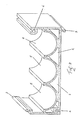
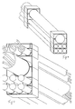
- Fig.1 shows the first of the modular members, the one utilized to support the tubings having a greater section, that is to say the ones suitable for containing the traditional cables or a set of three monotubes of a proper diameter for optical fiber cables.
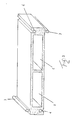
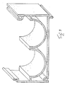
- Fig. 2 reports a second member: the one suitable for supporting the tubings having a smaller cross-section that contain the optical fiber cables.
- Fig. 3 shows a third member,the one with the function of plugging to close, suitable for being applied to the second member.
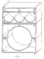
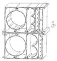
- Fig. 4 hypothesizes the assembly of a number of pieces to realize the support for a greater cross section tube and for a set of three smaller cross section tubes overlaying the first one.
- Figure 5 shows a bundle of ducts, realized only with small tubes that utilize four modules of the type depicted in Figure 2, superposed and closed by the plug of figure 3.
- the module 1 of figure 1 has a cradle of semicircular shape 1 supported by an essentially parallelepipedon structure lightened by large openings 2.
- the structure presents the shaped projections 3 by a part and the shaped slot 4 by the other, by the major sides for all the length of the minor sides.
- the module of Fig. 2 presents three cradles 5, arranged side by side, made up of semicircles of such a diameter, as to be able to support each one a tubing of the ones utilized to contain the optical fiber cables, in this case also there are the apertures 2.
- this module is equal to those of the module of Fig.1, and it presents the same projections and slots to be able to fix itself thereto.
- the module of Fig.3 also has cells arranged side by side 2 and is in the shape of a parallelepipedon with both its greater faces closed, the slots 4 and the projections 3 for the reciprocal fixation are equally present, its length and width are identical to those of the two other modules.
- the plug acting module can be usefully utilized as the final closure member.
- the suggested modular system affords the advantage of an easy assembly and of a large field of configurations with a reduced number of members.
- the series of the pieces affords the possibility of combining different tubings or tubings of the same type, realizing numerous couplings suitable for any exigency, in particular it is possible to realize the coupling of cables of the traditional copper type in the 125 mm tubing and optical fiber cables in the monotubes, or the 125 mm tubing can be utilized as a spare tube for both traditional cables and optical fiber cables.
- the system proposed to install ducts for protection of cables is formed by modular elements which as clearly results in the drawings and also in the description of the patent, have an extremely light structure.
- the joining system is formed by cylindrical protrusions which guarantee the elements connection even if sudden stresses are applied to the structure.
Abstract
Description
- The recent use of optical fiber cables has required in respect to the traditional ducts a choice between different diameters.
- Considering the increasing usage of these new cables which more and more substitute the traditional ones, very often even in the installation of the latter it is preferred to also provide the tubings to be used for optical fiber cables to be laid later on.
- Therefore, more and more often one resorts to installing double ducts; that is to say to lay next to the traditional ones those to be use for the optical fiber cables.
- Ducts prearranged for receiving telephone cables provide a choice of cradle supports realized in several superimposed pieces.
- Devices designed to support protection ducts for cables are known; the European Patent n. 303044 proposes over laid elements that have to be firmly fastened to the ground by means of metallic brackets and bolts; furthermore special devices to tighten with a degree of elasticity the modular elements into a frame are required; the overall structure is quite complex and requires troublesome work for its assembly directly into the dug trench.
- The French Patent n. 2332634 is also known which illustrates modular moulded elements which can be clamped together by means of sockets into which protruding hooks are fitted to form a bolt. There is only one type of modular component so that as a result the ducts are formed by a one section conduit type; in addition the component elements are quite heavy because of the presence of the strengthening ribs and because the walls are solid.
- Also know is the German Patent n. 2510828 proposing a system of modular supports in accordance with the preamble of appended
claim 1, the first row of which has to be fastened to the ground by means of bolts after which other elements can be inserted using a complex system of tightening joints. - Both the German and the French patents achieve a light weight by basing the structure of the support member on a web (4) in the German, (2) in the French provided with transverse flanges for strength and to support the cable tubing.
- In contrast, the system according to the present invention is characterised in that each support member is formed with wide through apertures in a direction parallel to the direction of the cables to be supported so that there is no web perpendicular to this direction and the support member has substantially the form of a profile.
- The solving idea consists in having realized members suitably shaped and endowed with a fixed joint system that allows them to be coupled in such a way that all the necessary configurations can be obtained for supporting either traditional or optical fiber cables, it is also possible to realize the coupling of both type pipelines.
- This solving idea is shown in the annexed figures in an embodiment given as a matter of example and not of limitation.
- Fig.1 shows the first of the modular members, the one utilized to support the tubings having a greater section, that is to say the ones suitable for containing the traditional cables or a set of three monotubes of a proper diameter for optical fiber cables.
- Fig. 2 reports a second member: the one suitable for supporting the tubings having a smaller cross-section that contain the optical fiber cables.
- Fig. 3 shows a third member,the one with the function of plugging to close, suitable for being applied to the second member.
- Fig. 4 hypothesizes the assembly of a number of pieces to realize the support for a greater cross section tube and for a set of three smaller cross section tubes overlaying the first one.
- To realize this assembly, two pieces of the type of those depicted in Figure 1, one piece of those depicted in figure 2 and a piece as illustrated in figure 3 have been utilized.
- Figure 5 shows a bundle of ducts, realized only with small tubes that utilize four modules of the type depicted in Figure 2, superposed and closed by the plug of figure 3.
- The bundle in Figure 6, on the contrary, hypothesizes a central tube of a large size, closed by two rows of smaller cross section tubes and, lastly, the closing plug.
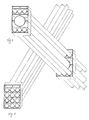
- Figures 7,8,9 and 10 report other possible coupling solutions, all obtained with the suggested modules.
- With reference to the Figures, therefore, the
module 1 of figure 1 has a cradle ofsemicircular shape 1 supported by an essentially parallelepipedon structure lightened bylarge openings 2. - The structure presents the
shaped projections 3 by a part and theshaped slot 4 by the other, by the major sides for all the length of the minor sides. - These members are interspersed in the sense that to a slot on a face a projection on the opposite face corresponds.
- The module of Fig. 2 presents three
cradles 5, arranged side by side, made up of semicircles of such a diameter, as to be able to support each one a tubing of the ones utilized to contain the optical fiber cables, in this case also there are theapertures 2. - The width and the length of this module are equal to those of the module of Fig.1, and it presents the same projections and slots to be able to fix itself thereto.
- The module of Fig.3 also has cells arranged side by
side 2 and is in the shape of a parallelepipedon with both its greater faces closed, theslots 4 and theprojections 3 for the reciprocal fixation are equally present, its length and width are identical to those of the two other modules. - It acts also as the closure member for the modules of Fig.2.
- The utilization of the suggested modular structure is evident from what has been disclosed and depicted.
- By virtue of the modular sizes and of the presence of the slots and of the transverse ridges, they can be combined in many configurations, some of which are illustrated in the annexed figures.
- Indeed, it suffices to rest the base member, to install the tube and then to superpose the other member fixing it on the first member to enclose the tubing and have at disposal the base of another support to be superposed, the plug acting module can be usefully utilized as the final closure member.
- The suggested modular system affords the advantage of an easy assembly and of a large field of configurations with a reduced number of members.
- The series of the pieces affords the possibility of combining different tubings or tubings of the same type, realizing numerous couplings suitable for any exigency, in particular it is possible to realize the coupling of cables of the traditional copper type in the 125 mm tubing and optical fiber cables in the monotubes, or the 125 mm tubing can be utilized as a spare tube for both traditional cables and optical fiber cables.
- The system proposed to install ducts for protection of cables is formed by modular elements which as clearly results in the drawings and also in the description of the patent, have an extremely light structure. The joining system is formed by cylindrical protrusions which guarantee the elements connection even if sudden stresses are applied to the structure.
- In the annexed figures one has hypothesized for the members of the series a size and a configuration which at the moment respond to the exigencies in the field of the installation of the telephone cables; however the possibility is not excluded of realizing configurations different for both diameters and number of cradles arranged side by side, without departing from the scope of the patent, whereto formal and structural variations can be anyhow made, without departing from its scope, which remains defined by the following claims.
Claims (6)
- A system of modular supports suitable for simultaneously supporting cable tubing of different diameters, the system comprising support members (1), each provided with a fixed joint system (3,4) allowing it to be clamped to laterally adjacent members, each support member presenting a shape inscribed in a parallelepipedon and comprising at least one cradle (5) adapted to support tubing of a distinct diameter characterised in that each support member (1) is constructed for light weight with wide through apertures (2) in a direction parallel to the direction of the tubing to be supported, such that there is substantially no web perpendicular to the said direction.
- The system according to claim 1 wherein the joint system comprises a projection (3) and a slot (4) provided on each of the opposed largest bases of the said parallelepipedon and adapted to clampingly engage a corresponding slot and projection respectively provided on a largest base of an adjacent parallelepipedon.
- the system according to claim 2 wherein a said projection and slot are provided on each base of the parallelepipedon, the said projections and slots being arranged parallel to the shortest sides of the greatest base of the said parallelepipedon.
- The system according to any of claims 1 to 3 wherein the support member comprises one or more cradles in the form of circular arcs arranged side by side.
- The system according to claim 4 wherein the circular arc is a semicircle.
- The system according to any of claims 1 to 5 further comprising a closure member having a perfectly parallelepipedon shape and adapted to perform exclusively the function of closure plug for the said support members.
Applications Claiming Priority (2)
| Application Number | Priority Date | Filing Date | Title |
|---|---|---|---|
| IT04044890A IT1246947B (en) | 1990-11-13 | 1990-11-13 | MODULAR SUPPORT SYSTEM CONSTITUTED BY THREE PIECES SUITABLE FOR RECEIVING DIFFERENT DIAMETER DUCTS |
| IT4044890 | 1990-11-13 |
Publications (2)
| Publication Number | Publication Date |
|---|---|
| EP0486442A1 EP0486442A1 (en) | 1992-05-20 |
| EP0486442B1 true EP0486442B1 (en) | 1995-10-04 |
Family
ID=11249809
Family Applications (1)
| Application Number | Title | Priority Date | Filing Date |
|---|---|---|---|
| EP91830494A Expired - Lifetime EP0486442B1 (en) | 1990-11-13 | 1991-11-12 | A system of modular supports made up of three or more pieces, suitable for receiving ducts of different diameters |
Country Status (5)
| Country | Link |
|---|---|
| EP (1) | EP0486442B1 (en) |
| AT (1) | ATE128795T1 (en) |
| DE (1) | DE69113578D1 (en) |
| IT (1) | IT1246947B (en) |
| PT (1) | PT99318A (en) |
Cited By (11)
| Publication number | Priority date | Publication date | Assignee | Title |
|---|---|---|---|---|
| US6715719B2 (en) | 2002-03-27 | 2004-04-06 | Adc Telecommunications, Inc. | Coupler for cable trough |
| US7029195B2 (en) | 2002-03-27 | 2006-04-18 | Adc Telecommunications, Inc. | Coupler for cable trough |
| US7175137B2 (en) | 2001-11-16 | 2007-02-13 | Adc Telecommunications, Inc. | Coupler for cable trough |
| US7315680B1 (en) | 2006-06-21 | 2008-01-01 | Adc Telecommunications, Inc. | Cable routing devices with integrated couplers |
| US7463809B2 (en) | 2007-02-21 | 2008-12-09 | Adc Telecommunications, Inc. | Coupler for cable trough |
| US7481597B2 (en) | 2007-02-21 | 2009-01-27 | Adc Telecommunications, Inc. | Coupler for cable trough |
| US7493005B2 (en) | 2007-02-21 | 2009-02-17 | Adc Telecommunications, Inc. | Coupler for cable trough |
| US7504583B2 (en) | 2007-02-21 | 2009-03-17 | Adc Telecommunications, Inc. | Coupler for cable trough |
| US7584929B2 (en) | 2007-02-21 | 2009-09-08 | Adc Telecommunications, Inc. | Coupler for cable trough |
| US7815152B2 (en) | 2007-02-21 | 2010-10-19 | Adc Telecommunications, Inc. | Coupler for cable trough |
| US7896295B2 (en) | 2007-02-21 | 2011-03-01 | Adc Telecommunications, Inc. | Coupler for cable trough |
Families Citing this family (5)
| Publication number | Priority date | Publication date | Assignee | Title |
|---|---|---|---|---|
| US6378811B1 (en) * | 1999-06-16 | 2002-04-30 | Panduit Corp. | Cable retainer |
| CN101440894B (en) * | 2007-11-23 | 2012-01-25 | 贵阳铝镁设计研究院有限公司 | Method and structure for arranging plant pipe network |
| DE112010004690B4 (en) | 2009-02-18 | 2017-12-28 | Commscope Inc. Of North Carolina | Retainer ring with a lower profile front |
| DE202015007620U1 (en) | 2015-11-04 | 2015-12-15 | Fkb Gmbh | Guide or holding device for holding pipes, cables or hoses |
| FR3124646B1 (en) * | 2021-06-25 | 2023-07-14 | Micab | Ribbon cable organization bar, cable organization assembly comprising such bars, and method of assembling such an organization assembly |
Family Cites Families (2)
| Publication number | Priority date | Publication date | Assignee | Title |
|---|---|---|---|---|
| FR2280012A1 (en) * | 1974-03-14 | 1976-02-20 | Morel Atel Electro Meca Favier | SUPPORT ELEMENT FOR TUBULAR PIPELINES |
| FR2332634A1 (en) * | 1975-11-19 | 1977-06-17 | Electroformage Plastiques Cie | Support for underground cables and conduits - may be stacked by interlocking thermoplastic walls with snap fitting tongues and grooves |
-
1990
- 1990-11-13 IT IT04044890A patent/IT1246947B/en active IP Right Grant
-
1991
- 1991-10-24 PT PT99318A patent/PT99318A/en not_active Application Discontinuation
- 1991-11-12 AT AT91830494T patent/ATE128795T1/en active
- 1991-11-12 EP EP91830494A patent/EP0486442B1/en not_active Expired - Lifetime
- 1991-11-12 DE DE69113578T patent/DE69113578D1/en not_active Expired - Lifetime
Cited By (21)
| Publication number | Priority date | Publication date | Assignee | Title |
|---|---|---|---|---|
| US8186633B2 (en) | 2001-11-16 | 2012-05-29 | Adc Telecommunications, Inc. | Coupler for cable trough |
| US7175137B2 (en) | 2001-11-16 | 2007-02-13 | Adc Telecommunications, Inc. | Coupler for cable trough |
| US7360743B2 (en) | 2001-11-16 | 2008-04-22 | Adc Telecommunications, Inc. | Coupler for cable trough |
| US8444095B2 (en) | 2001-11-16 | 2013-05-21 | Adc Telecommunications, Inc. | Coupler for cable trough |
| US10114189B2 (en) | 2002-03-27 | 2018-10-30 | Commscope Technologies Llc | Coupler for cable trough |
| US9104004B2 (en) | 2002-03-27 | 2015-08-11 | Adc Telecommunications, Inc. | Coupler for cable trough |
| US7614817B2 (en) | 2002-03-27 | 2009-11-10 | Adc Telecommunications, Inc. | Coupler for cable trough |
| US8365384B2 (en) | 2002-03-27 | 2013-02-05 | Adc Telecommunications, Inc. | Coupler for cable trough |
| US7029195B2 (en) | 2002-03-27 | 2006-04-18 | Adc Telecommunications, Inc. | Coupler for cable trough |
| US6715719B2 (en) | 2002-03-27 | 2004-04-06 | Adc Telecommunications, Inc. | Coupler for cable trough |
| US7093997B2 (en) | 2002-03-27 | 2006-08-22 | Adc Telecommunications, Inc. | Coupler for cable trough |
| US8256723B2 (en) | 2006-06-21 | 2012-09-04 | Adc Telecommunications, Inc. | Cable routing devices with integrated couplers |
| US7315680B1 (en) | 2006-06-21 | 2008-01-01 | Adc Telecommunications, Inc. | Cable routing devices with integrated couplers |
| US7922129B2 (en) | 2006-06-21 | 2011-04-12 | Adc Telecommunications, Inc. | Cable routing devices with integrated couplers |
| US7896295B2 (en) | 2007-02-21 | 2011-03-01 | Adc Telecommunications, Inc. | Coupler for cable trough |
| US7504583B2 (en) | 2007-02-21 | 2009-03-17 | Adc Telecommunications, Inc. | Coupler for cable trough |
| US7493005B2 (en) | 2007-02-21 | 2009-02-17 | Adc Telecommunications, Inc. | Coupler for cable trough |
| US7481597B2 (en) | 2007-02-21 | 2009-01-27 | Adc Telecommunications, Inc. | Coupler for cable trough |
| US7463809B2 (en) | 2007-02-21 | 2008-12-09 | Adc Telecommunications, Inc. | Coupler for cable trough |
| US7815152B2 (en) | 2007-02-21 | 2010-10-19 | Adc Telecommunications, Inc. | Coupler for cable trough |
| US7584929B2 (en) | 2007-02-21 | 2009-09-08 | Adc Telecommunications, Inc. | Coupler for cable trough |
Also Published As
| Publication number | Publication date |
|---|---|
| ATE128795T1 (en) | 1995-10-15 |
| PT99318A (en) | 1993-12-31 |
| EP0486442A1 (en) | 1992-05-20 |
| DE69113578D1 (en) | 1995-11-09 |
| IT9040448A0 (en) | 1990-11-13 |
| IT9040448A1 (en) | 1992-05-13 |
| IT1246947B (en) | 1994-11-29 |
Similar Documents
| Publication | Publication Date | Title |
|---|---|---|
| EP0486442B1 (en) | A system of modular supports made up of three or more pieces, suitable for receiving ducts of different diameters | |
| US6533472B1 (en) | Optical fiber splice closure assembly | |
| US6427400B1 (en) | Cable support apparatus | |
| US5067678A (en) | Optic cable management system | |
| RU2165095C2 (en) | Enclosure in the form of cap for fiber-optical cables | |
| US6170804B1 (en) | Method and apparatus for introducing a cable into a conduit | |
| US4733986A (en) | Splice plate for cable tray | |
| US7783152B2 (en) | Apparatus for restraining fiber optic cables | |
| US6628880B2 (en) | Fiber optic cable splice enclosure | |
| CN104583829A (en) | Cable clamp and telecommunications enclosure | |
| KR19990029836A (en) | Connection to connect two tubes to each other | |
| AU683991B2 (en) | A cable routing device | |
| US5141258A (en) | Expansion joint for conduit for cables | |
| MY112690A (en) | Suspended line for an optical fibre unit | |
| US6185876B1 (en) | Installation duct | |
| JPH06504180A (en) | Cable tray device and its connectors | |
| US4756594A (en) | Optic fiber interconnection system | |
| GB2245330A (en) | Stand-off support for pipe or cable | |
| CN214789657U (en) | Embedded skeleton seals throttle formula bellows | |
| CN216387521U (en) | Terminal bifurcation welding box with double outlets | |
| JP3197831B2 (en) | Guide tube fixture in buried pipe and fixing method | |
| CN220040834U (en) | Waterproof type connection structure and optical fiber connection divides fine case | |
| ES552520A0 (en) | A METHOD FOR ASSEMBLING AND INSTALLING TUBES AND A CORRESPONDING DEVICE. | |
| GB2350656A (en) | Apparatus for connecting a conduit with a corrugated outer surface to another element | |
| IES20000280A2 (en) | Improvements in and relating to conduits |
Legal Events
| Date | Code | Title | Description |
|---|---|---|---|
| PUAI | Public reference made under article 153(3) epc to a published international application that has entered the european phase |
Free format text: ORIGINAL CODE: 0009012 |
|
| AK | Designated contracting states |
Kind code of ref document: A1 Designated state(s): AT BE CH DE DK ES FR GB GR IT LI LU NL SE |
|
| 17P | Request for examination filed |
Effective date: 19921116 |
|
| 17Q | First examination report despatched |
Effective date: 19940304 |
|
| GRAA | (expected) grant |
Free format text: ORIGINAL CODE: 0009210 |
|
| AK | Designated contracting states |
Kind code of ref document: B1 Designated state(s): AT BE CH DE DK ES FR GB GR IT LI LU NL SE |
|
| PG25 | Lapsed in a contracting state [announced via postgrant information from national office to epo] |
Ref country code: IT Free format text: LAPSE BECAUSE OF FAILURE TO SUBMIT A TRANSLATION OF THE DESCRIPTION OR TO PAY THE FEE WITHIN THE PRE;WARNING: LAPSES OF ITALIAN PATENTS WITH EFFECTIVE DATE BEFORE 2007 MAY HAVE OCCURRED AT ANY TIME BEFORE 2007. THE CORRECT EFFECTIVE DATE MAY BE DIFFERENT FROM THE ONE RECORDED.SCRIBED TIME-LIMIT Effective date: 19951004 Ref country code: FR Effective date: 19951004 Ref country code: BE Effective date: 19951004 Ref country code: GR Free format text: LAPSE BECAUSE OF FAILURE TO SUBMIT A TRANSLATION OF THE DESCRIPTION OR TO PAY THE FEE WITHIN THE PRESCRIBED TIME-LIMIT Effective date: 19951004 Ref country code: ES Free format text: THE PATENT HAS BEEN ANNULLED BY A DECISION OF A NATIONAL AUTHORITY Effective date: 19951004 Ref country code: NL Free format text: LAPSE BECAUSE OF NON-PAYMENT OF DUE FEES Effective date: 19951004 Ref country code: DK Effective date: 19951004 Ref country code: AT Effective date: 19951004 |
|
| REF | Corresponds to: |
Ref document number: 128795 Country of ref document: AT Date of ref document: 19951015 Kind code of ref document: T |
|
| REF | Corresponds to: |
Ref document number: 69113578 Country of ref document: DE Date of ref document: 19951109 |
|
| PG25 | Lapsed in a contracting state [announced via postgrant information from national office to epo] |
Ref country code: LU Free format text: LAPSE BECAUSE OF NON-PAYMENT OF DUE FEES Effective date: 19951130 |
|
| PGFP | Annual fee paid to national office [announced via postgrant information from national office to epo] |
Ref country code: CH Payment date: 19951130 Year of fee payment: 5 |
|
| PG25 | Lapsed in a contracting state [announced via postgrant information from national office to epo] |
Ref country code: SE Effective date: 19960104 Ref country code: GB Effective date: 19960104 |
|
| PG25 | Lapsed in a contracting state [announced via postgrant information from national office to epo] |
Ref country code: DE Effective date: 19960105 |
|
| EN | Fr: translation not filed | ||
| NLV1 | Nl: lapsed or annulled due to failure to fulfill the requirements of art. 29p and 29m of the patents act | ||
| REG | Reference to a national code |
Ref country code: CH Ref legal event code: PL |
|
| PLBE | No opposition filed within time limit |
Free format text: ORIGINAL CODE: 0009261 |
|
| STAA | Information on the status of an ep patent application or granted ep patent |
Free format text: STATUS: NO OPPOSITION FILED WITHIN TIME LIMIT |
|
| GBPC | Gb: european patent ceased through non-payment of renewal fee |
Effective date: 19960104 |
|
| 26N | No opposition filed | ||
| PG25 | Lapsed in a contracting state [announced via postgrant information from national office to epo] |
Ref country code: LI Free format text: LAPSE BECAUSE OF FAILURE TO SUBMIT A TRANSLATION OF THE DESCRIPTION OR TO PAY THE FEE WITHIN THE PRESCRIBED TIME-LIMIT Effective date: 19961130 Ref country code: CH Free format text: LAPSE BECAUSE OF FAILURE TO SUBMIT A TRANSLATION OF THE DESCRIPTION OR TO PAY THE FEE WITHIN THE PRESCRIBED TIME-LIMIT Effective date: 19961130 |