EP0484906A2 - Head mounting device - Google Patents
Head mounting device Download PDFInfo
- Publication number
- EP0484906A2 EP0484906A2 EP91118909A EP91118909A EP0484906A2 EP 0484906 A2 EP0484906 A2 EP 0484906A2 EP 91118909 A EP91118909 A EP 91118909A EP 91118909 A EP91118909 A EP 91118909A EP 0484906 A2 EP0484906 A2 EP 0484906A2
- Authority
- EP
- European Patent Office
- Prior art keywords
- read
- flexure
- write head
- region
- substrate
- Prior art date
- Legal status (The legal status is an assumption and is not a legal conclusion. Google has not performed a legal analysis and makes no representation as to the accuracy of the status listed.)
- Withdrawn
Links
Images


Classifications
-
- G—PHYSICS
- G11—INFORMATION STORAGE
- G11B—INFORMATION STORAGE BASED ON RELATIVE MOVEMENT BETWEEN RECORD CARRIER AND TRANSDUCER
- G11B33/00—Constructional parts, details or accessories not provided for in the other groups of this subclass
- G11B33/12—Disposition of constructional parts in the apparatus, e.g. of power supply, of modules
- G11B33/121—Disposition of constructional parts in the apparatus, e.g. of power supply, of modules the apparatus comprising a single recording/reproducing device
- G11B33/122—Arrangements for providing electrical connections, e.g. connectors, cables, switches
-
- G—PHYSICS
- G11—INFORMATION STORAGE
- G11B—INFORMATION STORAGE BASED ON RELATIVE MOVEMENT BETWEEN RECORD CARRIER AND TRANSDUCER
- G11B5/00—Recording by magnetisation or demagnetisation of a record carrier; Reproducing by magnetic means; Record carriers therefor
- G11B5/48—Disposition or mounting of heads or head supports relative to record carriers ; arrangements of heads, e.g. for scanning the record carrier to increase the relative speed
- G11B5/4806—Disposition or mounting of heads or head supports relative to record carriers ; arrangements of heads, e.g. for scanning the record carrier to increase the relative speed specially adapted for disk drive assemblies, e.g. assembly prior to operation, hard or flexible disk drives
- G11B5/486—Disposition or mounting of heads or head supports relative to record carriers ; arrangements of heads, e.g. for scanning the record carrier to increase the relative speed specially adapted for disk drive assemblies, e.g. assembly prior to operation, hard or flexible disk drives with provision for mounting or arranging electrical conducting means or circuits on or along the arm assembly
-
- G—PHYSICS
- G11—INFORMATION STORAGE
- G11B—INFORMATION STORAGE BASED ON RELATIVE MOVEMENT BETWEEN RECORD CARRIER AND TRANSDUCER
- G11B7/00—Recording or reproducing by optical means, e.g. recording using a thermal beam of optical radiation by modifying optical properties or the physical structure, reproducing using an optical beam at lower power by sensing optical properties; Record carriers therefor
- G11B7/08—Disposition or mounting of heads or light sources relatively to record carriers
-
- H—ELECTRICITY
- H01—ELECTRIC ELEMENTS
- H01R—ELECTRICALLY-CONDUCTIVE CONNECTIONS; STRUCTURAL ASSOCIATIONS OF A PLURALITY OF MUTUALLY-INSULATED ELECTRICAL CONNECTING ELEMENTS; COUPLING DEVICES; CURRENT COLLECTORS
- H01R12/00—Structural associations of a plurality of mutually-insulated electrical connecting elements, specially adapted for printed circuits, e.g. printed circuit boards [PCB], flat or ribbon cables, or like generally planar structures, e.g. terminal strips, terminal blocks; Coupling devices specially adapted for printed circuits, flat or ribbon cables, or like generally planar structures; Terminals specially adapted for contact with, or insertion into, printed circuits, flat or ribbon cables, or like generally planar structures
- H01R12/50—Fixed connections
- H01R12/59—Fixed connections for flexible printed circuits, flat or ribbon cables or like structures
-
- H—ELECTRICITY
- H05—ELECTRIC TECHNIQUES NOT OTHERWISE PROVIDED FOR
- H05K—PRINTED CIRCUITS; CASINGS OR CONSTRUCTIONAL DETAILS OF ELECTRIC APPARATUS; MANUFACTURE OF ASSEMBLAGES OF ELECTRICAL COMPONENTS
- H05K3/00—Apparatus or processes for manufacturing printed circuits
- H05K3/36—Assembling printed circuits with other printed circuits
- H05K3/361—Assembling flexible printed circuits with other printed circuits
- H05K3/363—Assembling flexible printed circuits with other printed circuits by soldering
Definitions
- the present invention relates to the field of disk drive memory units for computers, and more particularly to a read/write head mounting assembly for a floppy or rigid disk drive.
- Mass storage for computer or other information systems is typically provided by magnetic media storage systems, such as rigid or flexible disk storage systems.
- a rotating disk having a magnetic media layer on the surface is accessed by a "read/write" head, which is used to store and retrieve information from the disk surface.
- a "read/write" head To store information on a magnetic media disk, flux reversals are induced in the magnetic particles comprising the surface.
- a signal is induced in the head which can be decoded to provide information.
- data is stored on a magnetic disk on a series of spiral or concentric "tracks" on the surface of the disk.
- the read/write head moves back and forth radially on the disk so that it can be selectively positioned over one of the tracks. Once in position over a track, the head remains in place as the track rotates beneath it, allowing the head to read or write data on the track.
- a flexible media disk drive system also known as a "floppy disk drive” or “floppy drive”
- flexible magnetic media enclosed in a protective casing is inserted into a disk drive opening and accessed by a pair of read/write heads.
- One read/write head is on one side of the disk and an opposing read/write head mounted on the opposite side of the disk.
- An opening in the protective casing allows the heads to contact the disk surface directly.
- One of the read/write heads is mounted on a flexure assembly which in turn is mounted on an arm assembly.
- the other read/write head is either mounted on a similar flexure assembly or a stiffer flexure assembly which in turn is mounted on an arm assembly.
- the mounting arms are coupled to or integral with a head carriage which, under the direction of a carriage motor, can be moved back and forth in a radial direction to position the heads over specific data tracks.
- the heads are spring-loaded onto the disk. This is accomplished by having one of the head mounting arms hinged and biased with an urging spring to cause the disk to be "squeezed" between the pair of read/write heads.
- FIG. 10 A typical prior art head mounting assembly for floppy disk drives is shown in Figure 10.
- Two cantilevered support arms 25 and 30 respectively are positioned on opposite sides of a removable floppy disk 20.
- the back ends of support arms 25 and 30 are attached to a carriage (not shown) that allows the free ends of support arms 25 and 30 to move in a radial direction across the top and bottom surfaces, respectively, of floppy disk 20 to transfer information to and from memory tracks located on the top and bottom surfaces of the disk.
- lower support arm 30 is affixed to the carriage, while upper support arm 25 is hinged or otherwise flexibly attached to allow upper arm 25 to be lifted away from lower arm 30 to allow insertion and removal of floppy disk 20.
- a spring urges the arm 25 toward the disk during drive operation.
- Each of the two support arms 25 and 30 has an electromagnetic read/write head 35 mounted adjacent to its free end.
- Each read/write head 35 is instead mounted to a mounting plate 75 (flexure assembly).
- plate 75 is typically made from a copper or stainless steel alloy and has a thickness of about 50 to 300 microns.
- Mounting plate 75 may have vairous shapes (two examples of which are shown in Figures 1 and 2) and can be attached to the support arm assemblies 25 and 30 in different ways. In a typical arrangement, one relatively flexible mounting plate and one relatively rigid mounting plate are used. The flexible plate is flexible enough to easily allow the read/write head to tilt to maintain continous contact with the surface of the floppy disk 20 while being resilient enough to prevent horizontal motion.
- the flexible plate is fixedly attached to its support arm.
- the other mounting plate is typically significantly stiffer than the flexible plate, so as to allow little or no tilt, but is attached to its support arm in such a way as to allow some vertical movement.
- flexure 75 may be provided with rectangular or L-shaped cutouts to define a central region of increased flexibility.
- Flexure 75 in turn is mounted over a rectangular aperture adjacent the free end of the applicable support arm. This aperture is indicated by reference numeral 50.
- an intermediate flexible circuit 55 is attached between flexure 75 and an anchor point 60 on support arm 25.
- Intermediate flexible circuit 55 typically consists of a flexible polymide strip approximately 50 microns in thickness.
- a number of conductive copper strips 110 are formed on the surface of intermediate flexible circuit 55, and contact surfaces 115 and 120 are formed at their respective back and front ends.
- the front edge of intermediate flexible circuit 55 is bonded to a central portion 45 of flexure 75 adjacent to read/write head 35. Electrical leads 95 of read/write head 35 are soldered to the contact surfaces 115.
- the other end of flexible circuit 55 is attached to an anchor point 60 on the back of upper support arm 25.
- a second flexible circuit 65 is also connected to anchor point 60. Alternately a wire or cable may be used. This second flexible circuit 65 connects intermediate flexible circuit 55 to the disk drive's electronics package mounted adjacent to the carriage.
- the intermediate flexible circuit 55 is required in the prior art to reduce the strain on the delicate leads 95 of read/write head 35 and to allow the free movement of flexure 75. If a single long flexible circuit were connected directly between read/write head 35 and the disk drive's remotely located electronics package, movement of the long flexible circuit as the carriage assembly moves back and forth in a radial direction with respect to floppy disk 20 would exert forces on flexure 75. These forces would inhibit the free movement necessary for read/write head 35 to maintain the degree of surface contact with the floppy disk 20 required for proper operation.
- intermediate flexible circuit 55 To prevent such interference, the back end of intermediate flexible circuit 55 must be anchored to the anchor point 60 to isolate read/write head 35 from the stresses induced by movement of the second flexible circuit 65. However, even with its end anchored, intermediate flexi ⁇ ble circuit 55 creates a certain amount of resistance to the free movement of read/write head 35.
- U.S. Patent No. 4,809,103 issued to Lazzari discloses a slider with an integrated magnetic head, preamplifier circuitry and readout lines. The readout lines are connected by wires to the rest of the disk drive electronics.
- the head assembly described in "Lazzari” is built on the 100 face of a single crystal silicon wafer. Due to the rigid nature on the silicon, it is necessary for this read/write assembly to be connected to a spring assembly to provide the vertical motion necessary to the operation of a read/write head assembly.
- the read/write head is mounted directly on the support means. Similarily, the support means carries the readout lines.
- “Lazzari” descibes the desirability of a preamplifier located close to the read/write head.
- "Lazzari” accomplishes that function with an integrated circuit built on the piece of silicon that serves as the support arm.
- the present invention is different in that it does not rely on the use of silicon to achieve its function. By avoiding the use of single crystal silicon, the present invention can be accomplished at a lower cost with greater durability.
- the integral head of "Lazzari” could not be accomplished without the use of a silicon substrate.
- a printed circuit board (“PCB”), rather than the metal plate of the prior art, forms the flexure that supports the read/write head.
- This PCB flexure in turn is mounted to the support arm of the disk drive actuator carriage.
- the PCB flexure is configured so as to provide a similar degree of flexibility as the metal flexure of the prior art.
- the electrical leads of the read/write head are connected to first ends of conductive strips formed on the surface of the PCB flexure. The other ends of the conductive strips are connected to the disk drive's electronics package by means of a single flexible circuit. Only one flexible circuit is required.
- PCB flexure The advantages of using a PCB flexure are realized by combining the mechanics of the head flexure and the electrical head connections into a single integrated component.
- electronic components such as a preamplifier may be mounted to the PCB flexure itself or on the flexible circuit connected to the PCB flexure, limiting the amount of noise and other interference that may degenerate the signals passing from the read/write head to the disk drive's electronics package.
- Figure 1 is a perspective view showing a floppy disk drive head mounting assembly of the prior art.
- Figure 2 is a bottom plan view of the lower support arm of the head mounting assembly of the prior art shown in Figure 1.
- Figure 3 is a side sectional view of the lower support arm of the head mounting assembly shown in Figure 2.
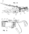
- Figure 4 is a perspective view of the preferred embodiment of the floppy disk drive head mounting assembly of the present invention.
- Figure 5 is a bottom view of the head mounting assembly of Figure 4.
- Figure 6 is a perspective view showing the interconnection between a flexible circuit and a metal flexure of the prior art.
- Figure 7 is a perspective view of the preferred embodiment of the PCB flexure of the present invention.
- Figure 8 is a top view of the PCB flexure shown in Figure 7.
- Figure 9 is a bottom view of the PCB flexure shown in Figure 7.
- Figure 10 is a perspective view of a prior art head mounting assembly for a floppy disk drive
- a head mounting scheme for a floppy disk drive is described.
- numerous specific details, such as disk size, capacity, etc. are set forth in detail in order to provide a more thorough understanding of the present invention. It will be apparent, however, to one skilled in the art, that the present invention may be practiced without these specific details. In other instances, well known features have not been described in detail so as not to unnecessarily obscure the present invention.
- FIG. 4-5 The preferred embodiment of the floppy disk drive head mounting assembly of the present invention is shown in Figures 4-5.
- the basic structure of the head mounting assembly of the present invention is similar to that of the prior art.
- Upper and lower support arms 225 and 230, respectively, are mounted to a carriage 215.
- Electromagnetic read/write heads 235 are mounted to flexures 275 adjacent the free ends of support arms 225 and 230.
- Carriage 215 rides on rails mounted to the chassis of the floppy disk drive unit by means of bearings 212.
- a removable floppy disk can be inserted between upper and lower support arms 225 and 230.
- Flexures 275 are resilient enough to accurately maintain read/write heads 235 in a fixed horizontal position with respect to the floppy disk yet flexible enough to allow a limited range of vertical movement to compensate for irregularities in the position of the floppy disk. This vertical compliance insures that read/write heads 235 maintain continuous contact with the surface of the floppy disk as it rotates about its axle.
- the position of the carriage, and, consequently, read/write heads 235, is controlled by an electronic servo control system which forms part of the disk drive's electronics contained on a printed circuit board mounted to the chassis of the disk drive unit.
- the flexure supporting the read/write head is made of metal, and an intermediate flexible circuit is required to provide electrical contact between the read/write head and the main flexible circuit leading to the disk drive's electronic package.
- the flexure 275 is made from printed circuit board material, and the flexure 275 itself is used to for electrical connection between the read/write head and the disk drive's electronics. The need for an intermediate flexible circuit of the prior art is thereby eliminated.
- flexure 275 is actually a specially designed printed circuit board.
- flexure 275 consists of a thin, rectangular wafer of a resilient, non-conductive substrate such as resin impregnated fiberglass, as is commonly used in the fabrication of printed circuit boards.
- this substrate preferably has a density of approximately 0.10 Lb M/In3 (pounds mass/cubic inch) and a modulus of elasticity of approximately 1x10⁶ Lb F/In2 (pounds force/square inch). This compares to typical values for stainless steel and copper alloy used for flexures of the prior art as follows. Material Density Modulus of Elasticity Stainless Steel 0.28 Lb M/In3 28x106 Lb F/In2 Copper Alloy 0.30 Lb M/In3 19x106 Lb F/In2
- a series of conductive strips 280 are formed on one of the surfaces of flexure 275.
- the conductive strips 280 are located on the flexure's bottom surface.
- the conductive strips may alternatively be located on the top surface or may even be sandwiched in between two substrate layers in a configuration analogous to a multi-layered printed circuit board.
- the conductive strips 280 run from a first set of contact surfaces 290 located adjacent the perimeter of flexure 275 to a second set of contract surfaces 295 located adjacent to the read/write head 235.
- Read/write head 235 is preferably mounted to flexure 275 by an epoxy adhesive, and the electrical leads 295 of the read/write head 235 are soldered to contact surfaces 285.
- both the contact surfaces 290 and read/write head 235 are fixedly attached adjacent to each other to flexure 275, there is no movement of one with respect to the other, and no stress is places on the connection between contact surfaces 290 and the delicate read write head wire leads (In the prior art, the movement of the intermediate flexible circuit attached to the read/write head can cause damage to the read/write head wire leads).
- flexure 275 is bonded to the sides of rectangular aperture 250 by means of an epoxy adhesive.
- a single flexible circuit segment 260 is used to connect the contact surfaces 290 (shown in Figure 9) directly to the disk drive's electronics. Because contact surfaces 290 are located adjacent to the edges of flexure 275, which are fixedly bonded to support arm 235, contact surfaces 290 exhibit very little movement as the central portion of flexure 275 flexes to compensate for any surface irregularities of the floppy disk. Contact surfaces 290 therefore form sturdy contact points to which flexible circuit 260 can be attached.
- certain electrical components such as a preamplifier 300 and associated electrical components are mounted directly on flexible circuit 260 adjacent to flexure 275.
- these components can be mounted directly to the PCB flexure 275.
- the length of the path that signals have to travel from read/write head 275 to preamplifier 300 is thereby greatly reduced as compared to the prior art, and the amount of outside interference (noise) to which signals from the read/write head are exposed is minimized.
- the signal to noise ratio is increased, the strength of the magnetic field required to receive an error free signal from read/write head 235 is reduced, and a smaller portion (magnetic domain) of the magnetic surface of floppy disk 220 is needed to store a given amount of data.
- a greater number of memory regions (magnetic domains) can be packed onto a floppy disk, and increased storage capacities can be attained.
- the present invention simplifies the fabrication of a floppy disk drive head assembly by reducing the number of flexible circuits required to connect a read/write head to external electronic circuitry and by simplifying and strengthening the electrical connections to the read/write head.
- the PCB head mounting flexure of the present invention forms a sturdy platform for connecting a flexible circuit to the read/write head. It also allows a preamplifier or other electronic circuitry to be mounted to the PCB flexure itself or to the flexible circuit. The strength of a signal required to accurately transfer information to and from a floppy disk is thereby reduced, allowing for greater floppy disk storage capacities.
- the present invention has been described with respect to the present preferred embodiment, other embodiments incorporating the inventive features of the present invention are possible.
- the PCB flexure may be supported only at one end, such that it becomes a cantilevered flexure.
- This configuration of the flexure of the present invention would be suitable for use, for example, in a hard disk drive unit.
- the flexibility of the flexure can easily be changed by varying the thickness or the geometry of the flexure or by fabricating the flexure from different substrate materials or by introducing voids (holes or grooves) in the PCB flexure.
- the PCB flexure of the present invention may contain additional electrical components such as a preamplifier in addition to the conductive strips and the read/write head described above.
- the flexure of the present invention can be used with an optical read/write head as well as with the electromagnetic read/write head used in the preferred embodiment.
- the PCB flexure of the present invention can be used in any instance where it is desired to flexibly support a component requiring external electrical connections.
Abstract
Description
- The present invention relates to the field of disk drive memory units for computers, and more particularly to a read/write head mounting assembly for a floppy or rigid disk drive.
- Mass storage for computer or other information systems is typically provided by magnetic media storage systems, such as rigid or flexible disk storage systems. A rotating disk having a magnetic media layer on the surface is accessed by a "read/write" head, which is used to store and retrieve information from the disk surface. To store information on a magnetic media disk, flux reversals are induced in the magnetic particles comprising the surface. When a magnetic read/write head is passed over the flux reversals, a signal is induced in the head which can be decoded to provide information.
- Typically, data is stored on a magnetic disk on a series of spiral or concentric "tracks" on the surface of the disk. The read/write head moves back and forth radially on the disk so that it can be selectively positioned over one of the tracks. Once in position over a track, the head remains in place as the track rotates beneath it, allowing the head to read or write data on the track.
- In a flexible media disk drive system, also known as a "floppy disk drive" or "floppy drive," flexible magnetic media enclosed in a protective casing is inserted into a disk drive opening and accessed by a pair of read/write heads. One read/write head is on one side of the disk and an opposing read/write head mounted on the opposite side of the disk. An opening in the protective casing allows the heads to contact the disk surface directly. One of the read/write heads is mounted on a flexure assembly which in turn is mounted on an arm assembly. The other read/write head is either mounted on a similar flexure assembly or a stiffer flexure assembly which in turn is mounted on an arm assembly. Some prior art heads are mounted directly on the arm assembly without a flexure assembly. The mounting arms are coupled to or integral with a head carriage which, under the direction of a carriage motor, can be moved back and forth in a radial direction to position the heads over specific data tracks. To improve data integrity and to maintain accurate head position and alignment, the heads are spring-loaded onto the disk. This is accomplished by having one of the head mounting arms hinged and biased with an urging spring to cause the disk to be "squeezed" between the pair of read/write heads.
- A typical prior art head mounting assembly for floppy disk drives is shown in Figure 10. Two cantilevered
support arms removable floppy disk 20. The back ends ofsupport arms support arms floppy disk 20 to transfer information to and from memory tracks located on the top and bottom surfaces of the disk. Usuallylower support arm 30 is affixed to the carriage, whileupper support arm 25 is hinged or otherwise flexibly attached to allowupper arm 25 to be lifted away fromlower arm 30 to allow insertion and removal offloppy disk 20. A spring, not shown, urges thearm 25 toward the disk during drive operation. - Each of the two support
arms head 35 mounted adjacent to its free end. Each read/writehead 35, rather than being mounted directly to one of thesupport arms plate 75 is typically made from a copper or stainless steel alloy and has a thickness of about 50 to 300 microns.Mounting plate 75 may have vairous shapes (two examples of which are shown in Figures 1 and 2) and can be attached to thesupport arm assemblies floppy disk 20 while being resilient enough to prevent horizontal motion. To prevent vertical motion of the read/write head as well, the flexible plate is fixedly attached to its support arm. The other mounting plate is typically significantly stiffer than the flexible plate, so as to allow little or no tilt, but is attached to its support arm in such a way as to allow some vertical movement. Depending on the degree of flexibility desired,flexure 75 may be provided with rectangular or L-shaped cutouts to define a central region of increased flexibility. -
Flexure 75 in turn is mounted over a rectangular aperture adjacent the free end of the applicable support arm. This aperture is indicated byreference numeral 50. - Referring to Figures 2 and 3, an intermediate
flexible circuit 55 is attached betweenflexure 75 and ananchor point 60 onsupport arm 25. Alternatively, a wire or cable may be used. Intermediateflexible circuit 55 typically consists of a flexible polymide strip approximately 50 microns in thickness. As shown in Figure 6, a number ofconductive copper strips 110 are formed on the surface of intermediateflexible circuit 55, andcontact surfaces flexible circuit 55 is bonded to acentral portion 45 offlexure 75 adjacent to read/writehead 35. Electrical leads 95 of read/writehead 35 are soldered to thecontact surfaces 115. As shown in Figures 10 and 3, the other end offlexible circuit 55 is attached to ananchor point 60 on the back ofupper support arm 25. A secondflexible circuit 65 is also connected toanchor point 60. Alternately a wire or cable may be used. This secondflexible circuit 65 connects intermediateflexible circuit 55 to the disk drive's electronics package mounted adjacent to the carriage. - Two separate
flexible circuits 55 and 65 (or equivalent wires or cables) are required in prior art disk drives. The intermediateflexible circuit 55 is required in the prior art to reduce the strain on thedelicate leads 95 of read/writehead 35 and to allow the free movement offlexure 75. If a single long flexible circuit were connected directly between read/writehead 35 and the disk drive's remotely located electronics package, movement of the long flexible circuit as the carriage assembly moves back and forth in a radial direction with respect tofloppy disk 20 would exert forces onflexure 75. These forces would inhibit the free movement necessary for read/writehead 35 to maintain the degree of surface contact with thefloppy disk 20 required for proper operation. To prevent such interference, the back end of intermediateflexible circuit 55 must be anchored to theanchor point 60 to isolate read/writehead 35 from the stresses induced by movement of the secondflexible circuit 65. However, even with its end anchored, intermediate flexi̊blecircuit 55 creates a certain amount of resistance to the free movement of read/writehead 35. - Certain prior art improvements to read/write head mounting schemes have been proposed.
- U.S. Patent No. 4,809,103 issued to Lazzari discloses a slider with an integrated magnetic head, preamplifier circuitry and readout lines. The readout lines are connected by wires to the rest of the disk drive electronics. The head assembly described in "Lazzari" is built on the 100 face of a single crystal silicon wafer. Due to the rigid nature on the silicon, it is necessary for this read/write assembly to be connected to a spring assembly to provide the vertical motion necessary to the operation of a read/write head assembly.
- U.S Patent No. 4,432,027 issued to "Higuchi" describes a disk drive head assembly in which the head mounted on a elastic support plate and electrical connections ar made through electrical conductors formed on a flexible insulator. The flexible insulator is supported by the plate.
- U.S. Patent No. 4,819,094 issued to "Oberg" and U.S. Patent No. 4,823,217 issued to "Kato et al" describe traditional mounting schemes using metal spring plates and flex circuits. The invention described in "Oberg" uses a flexible circuit to make the electrical connection between the read/write head and the associated disk drive electronics. The flexible circuit serves the dual purpose of making the electrical connections and also damping the characteristic vibrations of the read/write head support arm. A similarflexibel circuit arrangement is disclosed in "Kato et al". One embodiment of "Kato et al" makes the electrical connections between a read/write head and associated disk drive electronics through the printed wiring on a flexible printed circuit board.
- "Higuchi", "Oberg", and "Kato et al" disclose the use of flexible circuits for connecting a read/write head to the disk drive electronics. None of these patents, however, uses a PC board as the support arm of the read/write head assembly. Mounting the head on the flexible circuit board, use of the PC board to support the head and to carry the readout lines appears to distinguish the present invention from those discussed above.
- In "Lazzari", the read/write head is mounted directly on the support means. Similarily, the support means carries the readout lines. In addition, "Lazzari" descibes the desirability of a preamplifier located close to the read/write head. "Lazzari" accomplishes that function with an integrated circuit built on the piece of silicon that serves as the support arm. The present invention is different in that it does not rely on the use of silicon to achieve its function. By avoiding the use of single crystal silicon, the present invention can be accomplished at a lower cost with greater durability. In addition, the integral head of "Lazzari" could not be accomplished without the use of a silicon substrate.
- It is an object of the present invention to simplify the method by which the drive control electronics connect with a floppy disk read/write head.
- It is a further object of the invention to provide a method to condition or process the electrical signals from the read/write head as near to the head as possible.
- It is further object of the invention to provide a multifunctional head suspension mounting.
- In the preferred embodiment of the present invention, a printed circuit board ("PCB"), rather than the metal plate of the prior art, forms the flexure that supports the read/write head. This PCB flexure in turn is mounted to the support arm of the disk drive actuator carriage. The PCB flexure is configured so as to provide a similar degree of flexibility as the metal flexure of the prior art. The electrical leads of the read/write head are connected to first ends of conductive strips formed on the surface of the PCB flexure. The other ends of the conductive strips are connected to the disk drive's electronics package by means of a single flexible circuit. Only one flexible circuit is required. The advantages of using a PCB flexure are realized by combining the mechanics of the head flexure and the electrical head connections into a single integrated component. In an additional embodiment, electronic components such as a preamplifier may be mounted to the PCB flexure itself or on the flexible circuit connected to the PCB flexure, limiting the amount of noise and other interference that may degenerate the signals passing from the read/write head to the disk drive's electronics package.
- Figure 1 is a perspective view showing a floppy disk drive head mounting assembly of the prior art.
- Figure 2 is a bottom plan view of the lower support arm of the head mounting assembly of the prior art shown in Figure 1.
- Figure 3 is a side sectional view of the lower support arm of the head mounting assembly shown in Figure 2.
- Figure 4 is a perspective view of the preferred embodiment of the floppy disk drive head mounting assembly of the present invention.
- Figure 5 is a bottom view of the head mounting assembly of Figure 4.
- Figure 6 is a perspective view showing the interconnection between a flexible circuit and a metal flexure of the prior art.
- Figure 7 is a perspective view of the preferred embodiment of the PCB flexure of the present invention.
- Figure 8 is a top view of the PCB flexure shown in Figure 7.
- Figure 9 is a bottom view of the PCB flexure shown in Figure 7.
- Figure 10 is a perspective view of a prior art head mounting assembly for a floppy disk drive
- A head mounting scheme for a floppy disk drive is described. In the following description, numerous specific details, such as disk size, capacity, etc., are set forth in detail in order to provide a more thorough understanding of the present invention. It will be apparent, however, to one skilled in the art, that the present invention may be practiced without these specific details. In other instances, well known features have not been described in detail so as not to unnecessarily obscure the present invention.
- The preferred embodiment of the floppy disk drive head mounting assembly of the present invention is shown in Figures 4-5. The basic structure of the head mounting assembly of the present invention is similar to that of the prior art. Upper and
lower support arms carriage 215. Electromagnetic read/write heads 235 are mounted toflexures 275 adjacent the free ends ofsupport arms Carriage 215 rides on rails mounted to the chassis of the floppy disk drive unit by means ofbearings 212. A removable floppy disk can be inserted between upper andlower support arms Flexures 275 are resilient enough to accurately maintain read/write heads 235 in a fixed horizontal position with respect to the floppy disk yet flexible enough to allow a limited range of vertical movement to compensate for irregularities in the position of the floppy disk. This vertical compliance insures that read/write heads 235 maintain continuous contact with the surface of the floppy disk as it rotates about its axle. The position of the carriage, and, consequently, read/writeheads 235, is controlled by an electronic servo control system which forms part of the disk drive's electronics contained on a printed circuit board mounted to the chassis of the disk drive unit. - In the prior art, the flexure supporting the read/write head is made of metal, and an intermediate flexible circuit is required to provide electrical contact between the read/write head and the main flexible circuit leading to the disk drive's electronic package. In the present invention the
flexure 275 is made from printed circuit board material, and theflexure 275 itself is used to for electrical connection between the read/write head and the disk drive's electronics. The need for an intermediate flexible circuit of the prior art is thereby eliminated. - The flexure of the present invention is shown in detail in Figures 7, 8, and 9. Instead of being formed of metal like a prior art flexure,
flexure 275 is actually a specially designed printed circuit board. As shown in Figure 7,flexure 275 consists of a thin, rectangular wafer of a resilient, non-conductive substrate such as resin impregnated fiberglass, as is commonly used in the fabrication of printed circuit boards. As used in the flexure of the present invention, this substrate preferably has a density of approximately 0.10 Lb M/In³ (pounds mass/cubic inch) and a modulus of elasticity of approximately 1x10⁶ Lb F/In² (pounds force/square inch). This compares to typical values for stainless steel and copper alloy used for flexures of the prior art as follows.Material Density Modulus of Elasticity Stainless Steel 0.28 Lb M/In³ 28x10⁶ Lb F/In² Copper Alloy 0.30 Lb M/In³ 19x10⁶ Lb F/In² - A series of
conductive strips 280, preferably of copper alloy, are formed on one of the surfaces offlexure 275. In the embodiment shown in Figures 7 8 and 9, theconductive strips 280 are located on the flexure's bottom surface. The conductive strips may alternatively be located on the top surface or may even be sandwiched in between two substrate layers in a configuration analogous to a multi-layered printed circuit board. Theconductive strips 280 run from a first set of contact surfaces 290 located adjacent the perimeter offlexure 275 to a second set of contract surfaces 295 located adjacent to the read/write head 235. Read/write head 235 is preferably mounted toflexure 275 by an epoxy adhesive, and theelectrical leads 295 of the read/write head 235 are soldered to contact surfaces 285. - Since both the contact surfaces 290 and read/
write head 235 are fixedly attached adjacent to each other to flexure 275, there is no movement of one with respect to the other, and no stress is places on the connection betweencontact surfaces 290 and the delicate read write head wire leads (In the prior art, the movement of the intermediate flexible circuit attached to the read/write head can cause damage to the read/write head wire leads). - As shown in Figures 4 and 5, the entire flexure-read\write head assembly is in turn mounted over a
rectangular aperture 250 inlower support arm 230. In thepreferred embodiment flexure 275 is bonded to the sides ofrectangular aperture 250 by means of an epoxy adhesive. A singleflexible circuit segment 260 is used to connect the contact surfaces 290 (shown in Figure 9) directly to the disk drive's electronics. Because contact surfaces 290 are located adjacent to the edges offlexure 275, which are fixedly bonded to supportarm 235, contact surfaces 290 exhibit very little movement as the central portion offlexure 275 flexes to compensate for any surface irregularities of the floppy disk. Contact surfaces 290 therefore form sturdy contact points to whichflexible circuit 260 can be attached. Because theconductive strips 280 offlexure 275 form a flexible yet sturdy electrical connection betweenflexible circuit 260 and read/write head 235, the separate intermediate flexible circuit of the prior art is no longer required. In addition, because of the support provided toflexible circuit 260 byflexure 275, additional electrical components can be supported onflexible circuit 260 without adversely affecting the freedom of movement of read/write head 235. - As shown in Figure 5, in the preferred embodiment of the present invention, certain electrical components such as a
preamplifier 300 and associated electrical components are mounted directly onflexible circuit 260 adjacent toflexure 275. Alternatively, these components can be mounted directly to thePCB flexure 275. The length of the path that signals have to travel from read/write head 275 topreamplifier 300 is thereby greatly reduced as compared to the prior art, and the amount of outside interference (noise) to which signals from the read/write head are exposed is minimized. As a result the signal to noise ratio is increased, the strength of the magnetic field required to receive an error free signal from read/write head 235 is reduced, and a smaller portion (magnetic domain) of the magnetic surface of floppy disk 220 is needed to store a given amount of data. As a result, a greater number of memory regions (magnetic domains) can be packed onto a floppy disk, and increased storage capacities can be attained. - Accordingly, the present invention simplifies the fabrication of a floppy disk drive head assembly by reducing the number of flexible circuits required to connect a read/write head to external electronic circuitry and by simplifying and strengthening the electrical connections to the read/write head. The PCB head mounting flexure of the present invention forms a sturdy platform for connecting a flexible circuit to the read/write head. It also allows a preamplifier or other electronic circuitry to be mounted to the PCB flexure itself or to the flexible circuit. The strength of a signal required to accurately transfer information to and from a floppy disk is thereby reduced, allowing for greater floppy disk storage capacities.
- Although the present invention has been described with respect to the present preferred embodiment, other embodiments incorporating the inventive features of the present invention are possible. For instance, instead of being supported on all four sides, the PCB flexure may be supported only at one end, such that it becomes a cantilevered flexure. This configuration of the flexure of the present invention would be suitable for use, for example, in a hard disk drive unit. The flexibility of the flexure can easily be changed by varying the thickness or the geometry of the flexure or by fabricating the flexure from different substrate materials or by introducing voids (holes or grooves) in the PCB flexure. The PCB flexure of the present invention may contain additional electrical components such as a preamplifier in addition to the conductive strips and the read/write head described above. The flexure of the present invention can be used with an optical read/write head as well as with the electromagnetic read/write head used in the preferred embodiment. In fact, the PCB flexure of the present invention can be used in any instance where it is desired to flexibly support a component requiring external electrical connections.
Claims (16)
- A flexure (275) for supporting a transducer (235) adjacent to a memory medium (220) characterized by
a low conductivity resilient substrate; and
a high conductivity region (280, 290, 295) formed on said subtrate. - The flexure of claim 1 characterized in that the transducer comprises a read/write head (235).
- The flexure of claim 2 characterized by a transducer mounting region to which the read/write head (235) is mounted and an external support mounting region by which the flexure (275) is mounted to an external support (225, 230) and wherein said high conductivity region forms an electrical connection (280) between said read/write head mounting region (295) and an external electrical contact region (290).
- An assembly for supporting a read/write head (235) adjacent to a memory medium (220) characterized by:
a support arm (225, 230) movable adjacent to said memory medium (220);
a flexure (275) affixed to said support arm (225, 230) for supporting said read/write head (235) adjacent to said memory medium (220), said flexure comprising:
a low conductivity resilient substrate; and
a high conductivity region (280, 290, 295) formed on said substrate. - The read/write head supporting assembly of claim 4 characterized in that the flexure (275) comprises a read/write head mounting region to which the read/write head is mounted and an external support mounting region by which the flexure is mounted to the support arm, and wherein said high conductivity region forms an electrical connection between said read/write head mounting region and an external electrical contact region of said flexure.
- The device of claim 3 or 5 characterized by a flexible circuit means comprising conductive element means, said conductive element means being electrically connected to said external electrical contact region (290) of said high conductivity region formed on said substrate.
- The device according to any of claims 1 to 6 characterized in that said substrate comprises a wafer of resin impregnated fiberglass.
- The device according to any of claims 1 to 6 characterized in that said substrate comprises a ceramic wafer.
- The device according to any of claims 1 to 6 characterized in that said substrate comprises a wafer of PCB material.
- The device according to claims 1 to 9 characterized by electrical component means (260) connected to said high conductivity region.
- The device of claim 10 characterized in that said electrical component means (260) comprises preamplifier (300) or signal conditioning means.
- The device according to any of claims 2 to 11 characterized in that said read/write head (235) comprises electromagnetic read/write head means.
- The device according to any of claims 2 to 11 characterized in that said read/write head comprises optical read/write head means.
- The device according to any of claims 4 to 13 characterized by carriage means for supporting said support arm.
- The device of claim 14 characterized in that said support arm is movably attached to said carriage means.
- A flexure (275) for resiliently supporting a component (235) requiring external electrical connections (280) characterized by
a low conductivity resilient substrate; and
a high conductivity region formed on said substrate for providing electrical connections.
Applications Claiming Priority (2)
| Application Number | Priority Date | Filing Date | Title |
|---|---|---|---|
| US61127190A | 1990-11-09 | 1990-11-09 | |
| US611271 | 1990-11-09 |
Publications (2)
| Publication Number | Publication Date |
|---|---|
| EP0484906A2 true EP0484906A2 (en) | 1992-05-13 |
| EP0484906A3 EP0484906A3 (en) | 1993-04-28 |
Family
ID=24448357
Family Applications (1)
| Application Number | Title | Priority Date | Filing Date |
|---|---|---|---|
| EP19910118909 Withdrawn EP0484906A3 (en) | 1990-11-09 | 1991-11-06 | Head mounting device |
Country Status (2)
| Country | Link |
|---|---|
| EP (1) | EP0484906A3 (en) |
| JP (1) | JPH06131645A (en) |
Cited By (14)
| Publication number | Priority date | Publication date | Assignee | Title |
|---|---|---|---|---|
| EP0671727A1 (en) * | 1994-03-08 | 1995-09-13 | Fujitsu Limited | Magnetic disk drive unit |
| US5491597A (en) * | 1994-04-15 | 1996-02-13 | Hutchinson Technology Incorporated | Gimbal flexure and electrical interconnect assembly |
| US5570261A (en) * | 1993-09-16 | 1996-10-29 | International Business Machines Corporation | Transducer suspension system |
| US5608591A (en) * | 1995-06-09 | 1997-03-04 | International Business Machines Corporation | Integrated head-electronics interconnection suspension for a data recording disk drive |
| US5808836A (en) * | 1995-08-30 | 1998-09-15 | International Business Machines Corporation | Load beam with grooved wire-gluing region |
| US5808834A (en) * | 1995-06-07 | 1998-09-15 | Hutchinson Technology Incorporated | Laminated adapter |
| US5835306A (en) * | 1995-06-07 | 1998-11-10 | Hutchinson Technology Incorporated | Integrated gimbal suspension assembly with assymetric bond pad |
| US5839193A (en) * | 1994-04-15 | 1998-11-24 | Hutchinson Technology Incorporated | Method of making laminated structures for a disk drive suspension assembly |
| US6002548A (en) * | 1992-11-27 | 1999-12-14 | Fujitsu Limited | Magnetic head supporting mechanism |
| US6021022A (en) * | 1997-10-27 | 2000-02-01 | Seagate Technology, Inc. | Flexure displacement limiter-flex circuit interconnect |
| US6144530A (en) * | 1997-12-24 | 2000-11-07 | Tdk Corporation | Magnetic head apparatus with head IC chip |
| EP1091353A1 (en) * | 1999-10-07 | 2001-04-11 | Deutsche Thomson-Brandt Gmbh | Appliance for reading from or writing to optical recording media |
| WO2001026099A1 (en) * | 1999-10-05 | 2001-04-12 | Questek Innovations, Inc. | Low impedance head/preamplifier chip position in a disk drive |
| US6522505B1 (en) | 1992-11-27 | 2003-02-18 | Fujitsu Limited | Magnetic head supporting mechanism |
Citations (10)
| Publication number | Priority date | Publication date | Assignee | Title |
|---|---|---|---|---|
| US4432027A (en) * | 1980-07-11 | 1984-02-14 | Canon Kabushiki Kaisha | Magnetic head |
| JPS59168968A (en) * | 1983-03-17 | 1984-09-22 | Fujitsu Ltd | Magnetic storage device |
| JPS6010415A (en) * | 1983-06-30 | 1985-01-19 | Nec Corp | Floating magnetic head |
| JPS60246015A (en) * | 1984-05-21 | 1985-12-05 | Nippon Telegr & Teleph Corp <Ntt> | Gimbal spring for magnetic head |
| JPS6214310A (en) * | 1985-07-12 | 1987-01-22 | Matsushita Electric Ind Co Ltd | Production of magnetic head |
| JPS6216212A (en) * | 1985-07-16 | 1987-01-24 | Seiko Epson Corp | Magnetic head |
| US4759119A (en) * | 1985-09-10 | 1988-07-26 | Alps Electric Co., Ltd. | Method of fabricating a magnetic head assembly |
| JPS63193319A (en) * | 1987-02-06 | 1988-08-10 | Fuji Elelctrochem Co Ltd | Magnetic head |
| JPS6419517A (en) * | 1987-07-15 | 1989-01-23 | Fuji Electrochemical Co Ltd | Method for mounting terminal plate on magnetic head gimbal |
| JPS6470910A (en) * | 1987-09-10 | 1989-03-16 | Matsushita Electric Ind Co Ltd | Magnetic head device |
-
1991
- 1991-11-06 EP EP19910118909 patent/EP0484906A3/en not_active Withdrawn
- 1991-11-11 JP JP32152991A patent/JPH06131645A/en active Pending
Patent Citations (10)
| Publication number | Priority date | Publication date | Assignee | Title |
|---|---|---|---|---|
| US4432027A (en) * | 1980-07-11 | 1984-02-14 | Canon Kabushiki Kaisha | Magnetic head |
| JPS59168968A (en) * | 1983-03-17 | 1984-09-22 | Fujitsu Ltd | Magnetic storage device |
| JPS6010415A (en) * | 1983-06-30 | 1985-01-19 | Nec Corp | Floating magnetic head |
| JPS60246015A (en) * | 1984-05-21 | 1985-12-05 | Nippon Telegr & Teleph Corp <Ntt> | Gimbal spring for magnetic head |
| JPS6214310A (en) * | 1985-07-12 | 1987-01-22 | Matsushita Electric Ind Co Ltd | Production of magnetic head |
| JPS6216212A (en) * | 1985-07-16 | 1987-01-24 | Seiko Epson Corp | Magnetic head |
| US4759119A (en) * | 1985-09-10 | 1988-07-26 | Alps Electric Co., Ltd. | Method of fabricating a magnetic head assembly |
| JPS63193319A (en) * | 1987-02-06 | 1988-08-10 | Fuji Elelctrochem Co Ltd | Magnetic head |
| JPS6419517A (en) * | 1987-07-15 | 1989-01-23 | Fuji Electrochemical Co Ltd | Method for mounting terminal plate on magnetic head gimbal |
| JPS6470910A (en) * | 1987-09-10 | 1989-03-16 | Matsushita Electric Ind Co Ltd | Magnetic head device |
Non-Patent Citations (8)
| Title |
|---|
| PATENT ABSTRACTS OF JAPAN vol. 009, no. 024 (P-331)31 January 1985 & JP-A-59 168 968 ( FUJITSU KK ) 22 September 1984 * |
| PATENT ABSTRACTS OF JAPAN vol. 009, no. 127 (P-360)31 May 1985 & JP-A-60 010 415 ( NIPPON DENKI KK ) 19 January 1985 * |
| PATENT ABSTRACTS OF JAPAN vol. 010, no. 116 (P-452)30 April 1986 & JP-A-60 246 015 ( NIPPON DENSHIN DENWA KOSHA ) 5 December 1985 * |
| PATENT ABSTRACTS OF JAPAN vol. 011, no. 189 (P-587)18 June 1987 & JP-A-62 014 310 ( MATSUSHITA ELECTRIC IND CO ) 22 January 1987 * |
| PATENT ABSTRACTS OF JAPAN vol. 012, no. 477 (P-800)14 December 1988 & JP-A-63 193 319 ( FUJI ELECTROCHEM CO LTD ) 10 August 1988 * |
| PATENT ABSTRACTS OF JAPAN vol. 013, no. 197 (P-868)11 May 1989 & JP-A-01 019 517 ( FUJI ELECTROCHEM CO LTD ) 23 January 1989 * |
| PATENT ABSTRACTS OF JAPAN vol. 013, no. 284 (P-892)29 June 1989 & JP-A-01 070 910 ( MATSUSHITA ELECTRIC IND CO LTD ) 16 March 1989 * |
| PATENT ABSTRACTS OF JAPAN vol. 11, no. 189 (P-587)18 June 1987 & JP-A-62 016 212 ( SEIKO EPSON CORP ) 24 January 1987 * |
Cited By (20)
| Publication number | Priority date | Publication date | Assignee | Title |
|---|---|---|---|---|
| US6002548A (en) * | 1992-11-27 | 1999-12-14 | Fujitsu Limited | Magnetic head supporting mechanism |
| US7221541B2 (en) | 1992-11-27 | 2007-05-22 | Fujitsu Limited | Magnetic head supporting mechanism |
| US6560073B1 (en) | 1992-11-27 | 2003-05-06 | Fujitsu Limited | Magnetic head supporting mechanism |
| US6522505B1 (en) | 1992-11-27 | 2003-02-18 | Fujitsu Limited | Magnetic head supporting mechanism |
| US6212041B1 (en) | 1992-11-27 | 2001-04-03 | Fujitsu Limited | Magnetic head supporting mechanism |
| US5570261A (en) * | 1993-09-16 | 1996-10-29 | International Business Machines Corporation | Transducer suspension system |
| US5786964A (en) * | 1994-03-08 | 1998-07-28 | Fujitsu Limited | Magnetic disk drive unit with improved signal feeding and extracting arrangement |
| EP0671727A1 (en) * | 1994-03-08 | 1995-09-13 | Fujitsu Limited | Magnetic disk drive unit |
| US5645735A (en) * | 1994-04-15 | 1997-07-08 | Hutchinson Technology Incorporated | Gimbal flexure and electrical interconnect assembly |
| US5839193A (en) * | 1994-04-15 | 1998-11-24 | Hutchinson Technology Incorporated | Method of making laminated structures for a disk drive suspension assembly |
| US5491597A (en) * | 1994-04-15 | 1996-02-13 | Hutchinson Technology Incorporated | Gimbal flexure and electrical interconnect assembly |
| US5835306A (en) * | 1995-06-07 | 1998-11-10 | Hutchinson Technology Incorporated | Integrated gimbal suspension assembly with assymetric bond pad |
| US5808834A (en) * | 1995-06-07 | 1998-09-15 | Hutchinson Technology Incorporated | Laminated adapter |
| US5608591A (en) * | 1995-06-09 | 1997-03-04 | International Business Machines Corporation | Integrated head-electronics interconnection suspension for a data recording disk drive |
| US5808836A (en) * | 1995-08-30 | 1998-09-15 | International Business Machines Corporation | Load beam with grooved wire-gluing region |
| US6112400A (en) * | 1995-08-30 | 2000-09-05 | International Business Machines Corporation | Apparatus and method for adhesively connecting wires to a suspension arm in a disk drive assembly |
| US6021022A (en) * | 1997-10-27 | 2000-02-01 | Seagate Technology, Inc. | Flexure displacement limiter-flex circuit interconnect |
| US6144530A (en) * | 1997-12-24 | 2000-11-07 | Tdk Corporation | Magnetic head apparatus with head IC chip |
| WO2001026099A1 (en) * | 1999-10-05 | 2001-04-12 | Questek Innovations, Inc. | Low impedance head/preamplifier chip position in a disk drive |
| EP1091353A1 (en) * | 1999-10-07 | 2001-04-11 | Deutsche Thomson-Brandt Gmbh | Appliance for reading from or writing to optical recording media |
Also Published As
| Publication number | Publication date |
|---|---|
| EP0484906A3 (en) | 1993-04-28 |
| JPH06131645A (en) | 1994-05-13 |
Similar Documents
| Publication | Publication Date | Title |
|---|---|---|
| US5818662A (en) | Static attitude and stiffness control for an integrated suspension | |
| US5644448A (en) | Head signal supply/retrieval structure for magnetic disk drive | |
| US6055132A (en) | Integrated lead suspension flexure for attaching a micro-actuator with a transducer slider | |
| CN1326119C (en) | Write/read head supporting mechanism, and write/read system | |
| KR100288806B1 (en) | Integrated head-electronics interconnection suspension for a data recording disk drive | |
| US5754369A (en) | Head suspension with self-shielding integrated conductor trace array | |
| EP0897575B1 (en) | A multi-piece integrated suspension assembly for a magnetic storage system | |
| EP0484906A2 (en) | Head mounting device | |
| US5969906A (en) | Transducer suspension system having access aperture | |
| US7414813B2 (en) | Vibration damped flexible circuit for use in a hard disk drive | |
| US5680275A (en) | Adjustable solder bump spacer for slider-suspension attachment | |
| US7130155B2 (en) | Head suspension assembly and magnetic disk apparatus comprising the head suspension assembly | |
| KR960011842B1 (en) | Magnetic disk apparatus | |
| US6097608A (en) | Disk drive vibration isolation using diaphragm isolators | |
| US5909342A (en) | Planar flexible circuit package for coupling transducers with carriage mounted circuitry | |
| US5276572A (en) | Magnetic disk apparatus | |
| KR930702746A (en) | High performance disk drive structure | |
| US20030081357A1 (en) | Printed circuit cable connector attachment assembly | |
| JP2729359B2 (en) | Disk drive device and method of assembling the same | |
| CN1096675C (en) | Slider suspension assembly and method for attaching slider to suspension in data-recording disk file | |
| US6219193B1 (en) | Superpositioning microactuator control and write current signals in a disc drive | |
| US5426549A (en) | Magnetic head positioning mechanism having electrical wiring plated thereupon | |
| US5815347A (en) | Information storage system having an improved planar head-suspension assembly | |
| US7116523B2 (en) | Interconnect module for use in a suspension assembly | |
| US20020154436A1 (en) | Micro-actuator transducer stack inertia cancellation control |
Legal Events
| Date | Code | Title | Description |
|---|---|---|---|
| PUAI | Public reference made under article 153(3) epc to a published international application that has entered the european phase |
Free format text: ORIGINAL CODE: 0009012 |
|
| AK | Designated contracting states |
Kind code of ref document: A2 Designated state(s): DE FR GB IT |
|
| PUAL | Search report despatched |
Free format text: ORIGINAL CODE: 0009013 |
|
| AK | Designated contracting states |
Kind code of ref document: A3 Designated state(s): DE FR GB IT |
|
| 17P | Request for examination filed |
Effective date: 19931025 |
|
| 17Q | First examination report despatched |
Effective date: 19931221 |
|
| STAA | Information on the status of an ep patent application or granted ep patent |
Free format text: STATUS: THE APPLICATION IS DEEMED TO BE WITHDRAWN |
|
| 18D | Application deemed to be withdrawn |
Effective date: 19960207 |