EP0483620A2 - Test plate apparatus - Google Patents
Test plate apparatus Download PDFInfo
- Publication number
- EP0483620A2 EP0483620A2 EP91117838A EP91117838A EP0483620A2 EP 0483620 A2 EP0483620 A2 EP 0483620A2 EP 91117838 A EP91117838 A EP 91117838A EP 91117838 A EP91117838 A EP 91117838A EP 0483620 A2 EP0483620 A2 EP 0483620A2
- Authority
- EP
- European Patent Office
- Prior art keywords
- wells
- volume
- test plate
- well
- tubular members
- Prior art date
- Legal status (The legal status is an assumption and is not a legal conclusion. Google has not performed a legal analysis and makes no representation as to the accuracy of the status listed.)
- Granted
Links
Images


Classifications
-
- B—PERFORMING OPERATIONS; TRANSPORTING
- B01—PHYSICAL OR CHEMICAL PROCESSES OR APPARATUS IN GENERAL
- B01L—CHEMICAL OR PHYSICAL LABORATORY APPARATUS FOR GENERAL USE
- B01L3/00—Containers or dishes for laboratory use, e.g. laboratory glassware; Droppers
- B01L3/50—Containers for the purpose of retaining a material to be analysed, e.g. test tubes
- B01L3/502—Containers for the purpose of retaining a material to be analysed, e.g. test tubes with fluid transport, e.g. in multi-compartment structures
- B01L3/5025—Containers for the purpose of retaining a material to be analysed, e.g. test tubes with fluid transport, e.g. in multi-compartment structures for parallel transport of multiple samples
- B01L3/50255—Multi-well filtration
-
- B—PERFORMING OPERATIONS; TRANSPORTING
- B01—PHYSICAL OR CHEMICAL PROCESSES OR APPARATUS IN GENERAL
- B01L—CHEMICAL OR PHYSICAL LABORATORY APPARATUS FOR GENERAL USE
- B01L3/00—Containers or dishes for laboratory use, e.g. laboratory glassware; Droppers
- B01L3/50—Containers for the purpose of retaining a material to be analysed, e.g. test tubes
- B01L3/508—Containers for the purpose of retaining a material to be analysed, e.g. test tubes rigid containers not provided for above
- B01L3/5085—Containers for the purpose of retaining a material to be analysed, e.g. test tubes rigid containers not provided for above for multiple samples, e.g. microtitration plates
-
- C—CHEMISTRY; METALLURGY
- C12—BIOCHEMISTRY; BEER; SPIRITS; WINE; VINEGAR; MICROBIOLOGY; ENZYMOLOGY; MUTATION OR GENETIC ENGINEERING
- C12M—APPARATUS FOR ENZYMOLOGY OR MICROBIOLOGY; APPARATUS FOR CULTURING MICROORGANISMS FOR PRODUCING BIOMASS, FOR GROWING CELLS OR FOR OBTAINING FERMENTATION OR METABOLIC PRODUCTS, i.e. BIOREACTORS OR FERMENTERS
- C12M23/00—Constructional details, e.g. recesses, hinges
- C12M23/02—Form or structure of the vessel
- C12M23/12—Well or multiwell plates
-
- B—PERFORMING OPERATIONS; TRANSPORTING
- B01—PHYSICAL OR CHEMICAL PROCESSES OR APPARATUS IN GENERAL
- B01L—CHEMICAL OR PHYSICAL LABORATORY APPARATUS FOR GENERAL USE
- B01L2200/00—Solutions for specific problems relating to chemical or physical laboratory apparatus
- B01L2200/02—Adapting objects or devices to another
- B01L2200/026—Fluid interfacing between devices or objects, e.g. connectors, inlet details
-
- B—PERFORMING OPERATIONS; TRANSPORTING
- B01—PHYSICAL OR CHEMICAL PROCESSES OR APPARATUS IN GENERAL
- B01L—CHEMICAL OR PHYSICAL LABORATORY APPARATUS FOR GENERAL USE
- B01L2300/00—Additional constructional details
- B01L2300/08—Geometry, shape and general structure
- B01L2300/0809—Geometry, shape and general structure rectangular shaped
- B01L2300/0829—Multi-well plates; Microtitration plates
-
- B—PERFORMING OPERATIONS; TRANSPORTING
- B01—PHYSICAL OR CHEMICAL PROCESSES OR APPARATUS IN GENERAL
- B01L—CHEMICAL OR PHYSICAL LABORATORY APPARATUS FOR GENERAL USE
- B01L3/00—Containers or dishes for laboratory use, e.g. laboratory glassware; Droppers
- B01L3/50—Containers for the purpose of retaining a material to be analysed, e.g. test tubes
- B01L3/508—Containers for the purpose of retaining a material to be analysed, e.g. test tubes rigid containers not provided for above
- B01L3/5085—Containers for the purpose of retaining a material to be analysed, e.g. test tubes rigid containers not provided for above for multiple samples, e.g. microtitration plates
- B01L3/50855—Containers for the purpose of retaining a material to be analysed, e.g. test tubes rigid containers not provided for above for multiple samples, e.g. microtitration plates using modular assemblies of strips or of individual wells
Definitions
- This invention relates to a test plate apparatus suitable for promoting fluid interactions such as by growing cells in a nutrient liquid within a multiplicity of wells. More particularly, this invention relates to such a test plate apparatus which permits adding or removing liquid from wells in the test plate without disturbing the material such as cells within the wells.
- multi-well test plates wherein the wells have a circular shape and size which permits the introduction therein of a tubular member having a membrane upon which cell attachment, growth and differentiation occurs.
- the microporous member allows free diffusion of ions and macromolecules between cells and their apical and basolateral surfaces through a liquid medium which surrounds the tubular member and which permeates the membrane.
- the test plates containing the wells are rectangular and having a standard size of about 3.25 inches by 5 inches in order to accommodate standard analytical apparatus. Since the plate size is defined and since it is desired to avoid corners in the wells to avoid liquid stagnation areas, the wells are circular. In addition, the clearance between the interior well wall and the outside wall of the tubular member insert is minimized.
- the member insert is generally as large as possible to maximize the cell growth-area which leads to a lower error in the data gathering.
- This space requirement renders it difficult to insert pipetting means into the well to remove or add liquid while the tubular member is positioned within the well.
- the periodic removal of liquid to remove cell waste and additions of liquid to provide cell nutrients is required to maintain cell viability.
- cell based assay protocols require fluid manipulation.
- automatically controlled pipetting means cannot be used since the tubular member position is random and the probability that the pipetting means would damage the cells and pierce the membrane is high.
- the present invention provides a test plate having wells shaped to accommodate a device, including a membrane which permits cell growth on the membrane and to isolate the device within a first volume of the well so that a second volume of the well remains open.
- the second volume of the well communicates with the first volume of the well and is sufficiently large to provide an access area to accommodate a pipette for delivering or removing liquid to or from the well without disturbing cells in the device within a nondisturbed area of the well.
- the wells are formed in rows on the test plate. Means are provided for maintaining the cell-retaining device within the first volume comprising the nondisturbed area of the wells so that the cells are not disturbed when liquid is added to or removed from the second volume comprising the access are of the wells.
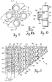
- Figure 1 is a top view of a test plate of the invention.
- Figure 2 is a cross-sectional view of the plate of Figure 1 taken along line 2-2.
- Figure 3 is a top view of a strip of a plurality of cell retention devices useful in the present invention.
- Figure 4 is a side view of the strip of Figure 3.
- Figure 5 is a top view of the test plate of Figure 1 with the strip of Figure 3 in place.
- Figure 6 is a cross-sectional view of the device of Figure 5 taken along line 6-6.
- Figure 7 is a cross-sectional view of a single cell retention device useful in the present invention.
- Figure 8 is a partial top view of the cell retention device of Figure 7 in place within a well of the plate of Figure 1.
- Figure 9 is a top view of cluster of wells useful in the present invention.
- Figure 10 is a cross-sectional view of the cluster of Figure 9 taken along line 10-10 without showing the wells.
- Figure 11 is a top view of various well designs useful in the present invention while accommodating the strip of Figure 3.
- Figure 12 is a top view of well having an extension from the well wall to restrict movement of a tubular member.
- Figure 13 is a side view of the well of Figure 12.
- Figure 14 is a top view of a well having an extension from the well floor to restrict movement of a tubular member.
- Figure 15 is a side view of the well of Figure 14.
- This invention is based upon the concept of providing a test plate containing a plurality of wells shaped to accommodate means for retaining cells and for allowing cell growth while permitting automatically controlled manipulation procedures to promote cell growth without adversely affecting cell growth.
- means are provided to maintain the means for retaining cells within a first volume of the well while permitting access to a second volume of the well with means for promoting cell growth without disturbing the growing cells.
- the means for positioning the cell retaining means can comprise the well shape or can comprise complementary ridge and slot means forming part of the cell retaining means and the plate.
- a plate 10 is shown for illustration purposes which include a plurality of wells 12.
- the wells have a tear-drop shape comprising a circular portion cross section 14 and a triangular section 16 formed from the two converging legs 18 and 20.
- the tear-drop shaped wells 12 comprise a preferred form of the wells of this invention since the well is free of sharp corners where liquid can stagnate.
- a set of two rows of wells such as the row of six wells 22 and the row of six wells 24 are positioned so that the triangular sections such as sections 26 and 28 extend into a central portion 30 positioned between the circular portion cross section 32 and 34 of wells 12.
- Slots 36 are provided in the solid portions of the plate 10 between wells 12 for reasons which will be explained below.
- a shelf 38 can be provided in order to support a cover over the wells 12 if desired.
- an additional number of wells can be provided in area 40 if desired.
- Figures 3 and 4 show a unitary strip 42, including a plurality of tubular members 44 having open ends 46 and a bottom which is rendered closed by having a membrane 48 sealed thereto.
- the strip 42 includes a segmented ridge 50 which fits into slots 36 when the strip 42 is positioned within a row of wells 12 in plate 10 (see Figures 1 and 5).
- the strip 42 is provided with end ridges 52 and 54 which contact an inner surface of a well 12 at the ends of each row of wells.
- the slots 36, ridge 50 and end ridges 52 and 54 serve to maintain the tubular members in place within the circular portion 14 of wells 12 (see Figure 5).
- the strip 42 is positioned so that the tubular member 44 having open end 46 fits within the circular portion 14 of wells 12.
- the tubular members 44 cannot enter the entire triangular portion 16 of well 12 because the width of the triangular portion 16 becomes less than the outer diameter of the tubular member 44. Thus, at least a portion of the triangular section remains open and free of the tublar member 44 so that pipetting can be effected within the triangular section 12 without disturbing cells on membrane 48 within the circular portion 14.
- the strip 42 can be provided with a handle 56 to promote ease of positioning the tubular members 44.
- additional wells 12 can be provided in plate 10 in the area occupied by the handles 56.
- an individual tubular member 47 is shown having an open end 58 and a closed end 60.
- the closed end 60 comprise a membrane 55 useful for growing cells such as is disclosed in U.S. Patent 4,917,793, which is incorporated herein by reference.
- the membrane 55 is sealed over the entire periphery of end 60. It is preferred that the tubular member 44 be transparent in order to enhance viewing of cell growth within membrane 55.
- the closed end 60 is immersed into an aqueous growth medium in well 12 and then viable cells are introduced onto membrane 55.
- Spaced apart protrusions 62 are provided to space membrane 55 apart from the bottom surface of well 12 so that both the top and bottom surfaces of the cells contact the growth medium.
- the growth medium outside of the tubular members 44 is periodically replaced with fresh growth medium by means of a pipette, which extends into triangular section 16 of well 12 without disturbing the cells or membrane 55 within tubular member 44.
- the media inside the well 46 need only be changed after the cells have attached and formed a monolayer by pipetting from inside the well 44.
- FIG. 9 and 10 An alternative means for including a plurality or tubular member on a unitary device is shown in Figures 9 and 10.
- the tubular member 44 and sealed membrane 55 are arranged as a cluster of four on a common central support 64 and arms 66.
- the tubular member 44 fit into four adjacently-positioned wells 12.
- the arms 66 can be provided with a notch 68 to permit easy breakage of the tubular member 44 from the arm 66.
- the means shown in Figures 9 and 10 can be expanded to include additional wells, e.g. 8, 12, 16, etc., if desired.
- the sets of complementary wells 68, 70, 72 and 74 do not require ridges in the strips 76, 78, 80 and 82 which complement slots in the plate 10 as explained above, since the outer diameter of the tubular member 44 in these wells is less than the width of the smaller portion of these wells.
- the tubular member 44 in wells 84 and 88 do not have areas with a diameter smaller than the outside diameter of the tubular member 44. Therefore, ridges 50 in the strips 90 and 92 are provided to maintain the member 44 in a portion of the wells 84 and 88 when a pipette is not inserted.
- the means for retaining the tubular members 44 within a given portion of the wells in plate 10 can comprise a complementary set of ridges and slots or, preferably, shaping the wells to have a portion of the wells with a diameter smaller than the outer diameter of the tubular members 44 on 47.
- the well shape for retaining the tubular member 47 can comprise an extension 94 extending from wall 96 of well 98.
- the well shape for retaining the tubular member 47 comprises an extension extending from the floor 93 of well 95.
- the distance between the extension 91 and the wall 97 is less than the outer diameter of tubular member 47 so that the tubular member 47 is retained within the area shown.
Abstract
Description
- This invention relates to a test plate apparatus suitable for promoting fluid interactions such as by growing cells in a nutrient liquid within a multiplicity of wells. More particularly, this invention relates to such a test plate apparatus which permits adding or removing liquid from wells in the test plate without disturbing the material such as cells within the wells.
- At the present time, multi-well test plates are provided wherein the wells have a circular shape and size which permits the introduction therein of a tubular member having a membrane upon which cell attachment, growth and differentiation occurs. The microporous member allows free diffusion of ions and macromolecules between cells and their apical and basolateral surfaces through a liquid medium which surrounds the tubular member and which permeates the membrane. The test plates containing the wells are rectangular and having a standard size of about 3.25 inches by 5 inches in order to accommodate standard analytical apparatus. Since the plate size is defined and since it is desired to avoid corners in the wells to avoid liquid stagnation areas, the wells are circular. In addition, the clearance between the interior well wall and the outside wall of the tubular member insert is minimized. The member insert is generally as large as possible to maximize the cell growth-area which leads to a lower error in the data gathering. However, a balance exists in that the basal and apical fluid volumes should be as close to equal for easy pipeting, to minimize fluid pressure between inner and outer wells and as large as possible to reduce the frequency of pipetting. This space requirement renders it difficult to insert pipetting means into the well to remove or add liquid while the tubular member is positioned within the well. The periodic removal of liquid to remove cell waste and additions of liquid to provide cell nutrients is required to maintain cell viability. In addition, cell based assay protocols require fluid manipulation. In addition, automatically controlled pipetting means cannot be used since the tubular member position is random and the probability that the pipetting means would damage the cells and pierce the membrane is high.
- Thus, it is presently necessary to pipette manually in order to avoid cell damage by the pipetting apparatus. This procedure is time-consuming, since it generally requires individual well treatment and is undesirable, since it may cause cell damage. Accordingly, it would be desirable to provide a test plate arrangement which permits removing or adding liquid from or to wells in the cell plate which permits the use of standard automatic pipetting means.
- The present invention provides a test plate having wells shaped to accommodate a device, including a membrane which permits cell growth on the membrane and to isolate the device within a first volume of the well so that a second volume of the well remains open. The second volume of the well communicates with the first volume of the well and is sufficiently large to provide an access area to accommodate a pipette for delivering or removing liquid to or from the well without disturbing cells in the device within a nondisturbed area of the well. The wells are formed in rows on the test plate. Means are provided for maintaining the cell-retaining device within the first volume comprising the nondisturbed area of the wells so that the cells are not disturbed when liquid is added to or removed from the second volume comprising the access are of the wells.
- Figure 1 is a top view of a test plate of the invention.
- Figure 2 is a cross-sectional view of the plate of Figure 1 taken along line 2-2.
- Figure 3 is a top view of a strip of a plurality of cell retention devices useful in the present invention.
- Figure 4 is a side view of the strip of Figure 3.
- Figure 5 is a top view of the test plate of Figure 1 with the strip of Figure 3 in place.
- Figure 6 is a cross-sectional view of the device of Figure 5 taken along line 6-6.
- Figure 7 is a cross-sectional view of a single cell retention device useful in the present invention.
- Figure 8 is a partial top view of the cell retention device of Figure 7 in place within a well of the plate of Figure 1.
- Figure 9 is a top view of cluster of wells useful in the present invention.
- Figure 10 is a cross-sectional view of the cluster of Figure 9 taken along line 10-10 without showing the wells.
- Figure 11 is a top view of various well designs useful in the present invention while accommodating the strip of Figure 3.
- Figure 12 is a top view of well having an extension from the well wall to restrict movement of a tubular member.
- Figure 13 is a side view of the well of Figure 12.
- Figure 14 is a top view of a well having an extension from the well floor to restrict movement of a tubular member.
- Figure 15 is a side view of the well of Figure 14.
- While the present invention is described in terms of effecting cell growth, it is to be understood that the present invention is applicable to manipulations involving an acces area for introducing or removing fluid and a nondisturbed area wherein the desired processing is effected, for example cell growth, dialysis or diffusional separation.
- This invention is based upon the concept of providing a test plate containing a plurality of wells shaped to accommodate means for retaining cells and for allowing cell growth while permitting automatically controlled manipulation procedures to promote cell growth without adversely affecting cell growth. In addition, means are provided to maintain the means for retaining cells within a first volume of the well while permitting access to a second volume of the well with means for promoting cell growth without disturbing the growing cells. The means for positioning the cell retaining means can comprise the well shape or can comprise complementary ridge and slot means forming part of the cell retaining means and the plate.
- Referring to Figure 1a
plate 10 is shown for illustration purposes which include a plurality ofwells 12. The wells have a tear-drop shape comprising a circularportion cross section 14 and atriangular section 16 formed from the twoconverging legs wells 12 comprise a preferred form of the wells of this invention since the well is free of sharp corners where liquid can stagnate. - A set of two rows of wells such as the row of six
wells 22 and the row of sixwells 24 are positioned so that the triangular sections such assections central portion 30 positioned between the circularportion cross section wells 12.Slots 36 are provided in the solid portions of theplate 10 betweenwells 12 for reasons which will be explained below. Ashelf 38 can be provided in order to support a cover over thewells 12 if desired. Furthermore, an additional number of wells can be provided inarea 40 if desired. - Figures 3 and 4 show a
unitary strip 42, including a plurality oftubular members 44 havingopen ends 46 and a bottom which is rendered closed by having amembrane 48 sealed thereto. Thestrip 42 includes asegmented ridge 50 which fits intoslots 36 when thestrip 42 is positioned within a row ofwells 12 in plate 10 (see Figures 1 and 5). Thestrip 42 is provided withend ridges well 12 at the ends of each row of wells. Theslots 36,ridge 50 andend ridges circular portion 14 of wells 12 (see Figure 5). As shown in Figure 5, thestrip 42 is positioned so that thetubular member 44 havingopen end 46 fits within thecircular portion 14 ofwells 12. Even if theridge 50 becomes dislodged from theslots 36, thetubular members 44 cannot enter the entiretriangular portion 16 of well 12 because the width of thetriangular portion 16 becomes less than the outer diameter of thetubular member 44. Thus, at least a portion of the triangular section remains open and free of thetublar member 44 so that pipetting can be effected within thetriangular section 12 without disturbing cells onmembrane 48 within thecircular portion 14. Thestrip 42 can be provided with ahandle 56 to promote ease of positioning thetubular members 44. Alternatively,additional wells 12 can be provided inplate 10 in the area occupied by thehandles 56. - Referring to Figures 7 and 8, an individual
tubular member 47 is shown having anopen end 58 and a closedend 60. The closedend 60 comprise amembrane 55 useful for growing cells such as is disclosed in U.S. Patent 4,917,793, which is incorporated herein by reference. Themembrane 55 is sealed over the entire periphery ofend 60. It is preferred that thetubular member 44 be transparent in order to enhance viewing of cell growth withinmembrane 55. In use, the closedend 60 is immersed into an aqueous growth medium in well 12 and then viable cells are introduced ontomembrane 55. Spaced apartprotrusions 62 are provided tospace membrane 55 apart from the bottom surface of well 12 so that both the top and bottom surfaces of the cells contact the growth medium. - The growth medium outside of the
tubular members 44 is periodically replaced with fresh growth medium by means of a pipette, which extends intotriangular section 16 of well 12 without disturbing the cells ormembrane 55 withintubular member 44. The media inside the well 46 need only be changed after the cells have attached and formed a monolayer by pipetting from inside thewell 44. - An alternative means for including a plurality or tubular member on a unitary device is shown in Figures 9 and 10. The
tubular member 44 and sealedmembrane 55 are arranged as a cluster of four on a commoncentral support 64 andarms 66. Thetubular member 44 fit into four adjacently-positionedwells 12. Thearms 66 can be provided with anotch 68 to permit easy breakage of thetubular member 44 from thearm 66. The means shown in Figures 9 and 10 can be expanded to include additional wells, e.g. 8, 12, 16, etc., if desired. - Referring to Figure 11, a plurality of differently-shaped wells are shown which are useful in the present invention.
- The sets of
complementary wells strips plate 10 as explained above, since the outer diameter of thetubular member 44 in these wells is less than the width of the smaller portion of these wells. Thetubular member 44 inwells tubular member 44. Therefore,ridges 50 in thestrips member 44 in a portion of thewells tubular members 44 within a given portion of the wells inplate 10 can comprise a complementary set of ridges and slots or, preferably, shaping the wells to have a portion of the wells with a diameter smaller than the outer diameter of thetubular members 44 on 47. - Referring to Figs. 12 and 13, the well shape for retaining the
tubular member 47 can comprise anextension 94 extending fromwall 96 ofwell 98. The distance between theend 99 ofextension 94 and the opposing portion ofwall 96 in less than the outer diameter oftubular member 47 so thattubular member 47 cnnot by-pass extension 94. - Referring to Figs. 14 and 15, the well shape for retaining the
tubular member 47 comprises an extension extending from thefloor 93 ofwell 95. The distance between theextension 91 and thewall 97 is less than the outer diameter oftubular member 47 so that thetubular member 47 is retained within the area shown.
Claims (9)
- A test plate having at least one set of wells, each of said set of wells comprising two essentially parallel rows of wells, each of said wells comprising a first volume for housing means for effecting a fluid interaction process and a second volume having a dimension smaller than an outside dimension of said housing means to prevent said housing means from entering said second volume, said second volume communicating with said first volume, said second volume having a shape which permits introduction of means for adding or removing liquid from said second volume.
- The test plate of Claim 1 wherein said wells have a tear-drop shape comprising a circular portion cross section for said first volume and a triangular-like cross section for said second volume formed from two converging legs.
- The test plate of claim 2 wherein a first well from a first row in each set has a first leg positioned essentially parallel to a second leg of a second well in a second row along substantially the entire length of said first leg and said second leg within a central area between said parallel rows.
- The test plate of claim 1 wherein said wells are L-shaped having a base section and a leg section wherein said leg sections extend into a central area between said parallel rows.
- The test plate of claim 1 including an extension means extending from a wall of each of said wells to prevent said housing means from entering said second volume.
- The test plate of claim 1 including an extension means extending from a floor of each of said wells to prevent said housing means from entering said second volume.
- Apparatus for growing cells which comprises, in combination, the test plate of any one of claims 1, 2, 3 or 4, a hollow tubular member positioned within each well of said test plate, said tubular member having an open end and a closed end covered by a porous membrane and means for maintaining said tubular membranes within the first volume of said wells.
- Apparatus for growing cells which comprises in combination the test plate of any one of claims 1, 2, 3 or 4, a plurality of hollow tubular members each positioned within a well of said test plate, said tubular members within a row of said test plate being molded integrally, each of said tubular members having an open end and closed end covered by a porous membrane, and means for maintaining said tubular members within the first volume of said wells.
- Apparatus for growing cells which comprises in combination the test plate of any one of claim 1, 2, 3 or 4, a plurality of hollow tubular members each positioned within a well of said test plate, a set of tubular members being formed integrally for positioning within adjacent wells of the adjacent rows of wells, each of said tubular members having an open end and a closed end covered by a porous membrane and means for maintaining said tubular members within the first volumes of said wells being positioned in adjacent rows of wells.
Applications Claiming Priority (2)
| Application Number | Priority Date | Filing Date | Title |
|---|---|---|---|
| US07/605,611 US5141718A (en) | 1990-10-30 | 1990-10-30 | Test plate apparatus |
| US605611 | 1990-10-30 |
Publications (3)
| Publication Number | Publication Date |
|---|---|
| EP0483620A2 true EP0483620A2 (en) | 1992-05-06 |
| EP0483620A3 EP0483620A3 (en) | 1992-12-09 |
| EP0483620B1 EP0483620B1 (en) | 1995-08-02 |
Family
ID=24424433
Family Applications (1)
| Application Number | Title | Priority Date | Filing Date |
|---|---|---|---|
| EP91117838A Expired - Lifetime EP0483620B1 (en) | 1990-10-30 | 1991-10-18 | Test plate apparatus |
Country Status (4)
| Country | Link |
|---|---|
| US (1) | US5141718A (en) |
| EP (1) | EP0483620B1 (en) |
| JP (1) | JP3121884B2 (en) |
| DE (1) | DE69111748T2 (en) |
Cited By (35)
| Publication number | Priority date | Publication date | Assignee | Title |
|---|---|---|---|---|
| US5358871A (en) * | 1993-01-13 | 1994-10-25 | Becton, Dickinson And Company | Culture vessel |
| EP0839182A1 (en) * | 1993-06-23 | 1998-05-06 | Martin L. Wolf | Dialyzed multiple well tissue culture plate |
| WO2002097029A2 (en) * | 2001-05-30 | 2002-12-05 | Biolex, Inc. | Plate and method for high throughput screening |
| WO2011012905A3 (en) * | 2009-07-31 | 2011-03-31 | Simon Stafford | Means for improved liquid handling in a microplate |
| WO2014143044A1 (en) * | 2013-03-15 | 2014-09-18 | Becton, Dickinson And Company | Process tube and carrier tray |
| US9259735B2 (en) | 2001-03-28 | 2016-02-16 | Handylab, Inc. | Methods and systems for control of microfluidic devices |
| US9347586B2 (en) | 2007-07-13 | 2016-05-24 | Handylab, Inc. | Automated pipetting apparatus having a combined liquid pump and pipette head system |
| USD759835S1 (en) | 2013-03-15 | 2016-06-21 | Becton, Dickinson And Company | Process tube strip |
| USD762873S1 (en) | 2013-03-15 | 2016-08-02 | Becton, Dickinson And Company | Process tube |
| US9480983B2 (en) | 2011-09-30 | 2016-11-01 | Becton, Dickinson And Company | Unitized reagent strip |
| US9528142B2 (en) | 2001-02-14 | 2016-12-27 | Handylab, Inc. | Heat-reduction methods and systems related to microfluidic devices |
| US9618139B2 (en) | 2007-07-13 | 2017-04-11 | Handylab, Inc. | Integrated heater and magnetic separator |
| USD787087S1 (en) | 2008-07-14 | 2017-05-16 | Handylab, Inc. | Housing |
| US9670528B2 (en) | 2003-07-31 | 2017-06-06 | Handylab, Inc. | Processing particle-containing samples |
| US9677121B2 (en) | 2001-03-28 | 2017-06-13 | Handylab, Inc. | Systems and methods for thermal actuation of microfluidic devices |
| US9765389B2 (en) | 2011-04-15 | 2017-09-19 | Becton, Dickinson And Company | Scanning real-time microfluidic thermocycler and methods for synchronized thermocycling and scanning optical detection |
| US9802199B2 (en) | 2006-03-24 | 2017-10-31 | Handylab, Inc. | Fluorescence detector for microfluidic diagnostic system |
| US9815057B2 (en) | 2006-11-14 | 2017-11-14 | Handylab, Inc. | Microfluidic cartridge and method of making same |
| US10065185B2 (en) | 2007-07-13 | 2018-09-04 | Handylab, Inc. | Microfluidic cartridge |
| US10071376B2 (en) | 2007-07-13 | 2018-09-11 | Handylab, Inc. | Integrated apparatus for performing nucleic acid extraction and diagnostic testing on multiple biological samples |
| US10100302B2 (en) | 2007-07-13 | 2018-10-16 | Handylab, Inc. | Polynucleotide capture materials, and methods of using same |
| USD831843S1 (en) | 2011-09-30 | 2018-10-23 | Becton, Dickinson And Company | Single piece reagent holder |
| US10179910B2 (en) | 2007-07-13 | 2019-01-15 | Handylab, Inc. | Rack for sample tubes and reagent holders |
| US10220392B2 (en) | 2013-03-15 | 2019-03-05 | Becton, Dickinson And Company | Process tube and carrier tray |
| WO2019014541A3 (en) * | 2017-07-13 | 2019-03-07 | Greiner Bio-One North America, Inc. | Culture plates for imaging |
| US10364456B2 (en) | 2004-05-03 | 2019-07-30 | Handylab, Inc. | Method for processing polynucleotide-containing samples |
| US10571935B2 (en) | 2001-03-28 | 2020-02-25 | Handylab, Inc. | Methods and systems for control of general purpose microfluidic devices |
| US10799862B2 (en) | 2006-03-24 | 2020-10-13 | Handylab, Inc. | Integrated system for processing microfluidic samples, and method of using same |
| US10822644B2 (en) | 2012-02-03 | 2020-11-03 | Becton, Dickinson And Company | External files for distribution of molecular diagnostic tests and determination of compatibility between tests |
| US10900066B2 (en) | 2006-03-24 | 2021-01-26 | Handylab, Inc. | Microfluidic system for amplifying and detecting polynucleotides in parallel |
| US11142785B2 (en) | 2006-03-24 | 2021-10-12 | Handylab, Inc. | Microfluidic system for amplifying and detecting polynucleotides in parallel |
| US11453906B2 (en) | 2011-11-04 | 2022-09-27 | Handylab, Inc. | Multiplexed diagnostic detection apparatus and methods |
| US11806718B2 (en) | 2006-03-24 | 2023-11-07 | Handylab, Inc. | Fluorescence detector for microfluidic diagnostic system |
| US11865544B2 (en) | 2013-03-15 | 2024-01-09 | Becton, Dickinson And Company | Process tube and carrier tray |
| US11959126B2 (en) | 2021-10-07 | 2024-04-16 | Handylab, Inc. | Microfluidic system for amplifying and detecting polynucleotides in parallel |
Families Citing this family (48)
| Publication number | Priority date | Publication date | Assignee | Title |
|---|---|---|---|---|
| US5264184A (en) * | 1991-03-19 | 1993-11-23 | Minnesota Mining And Manufacturing Company | Device and a method for separating liquid samples |
| CA2077853A1 (en) * | 1992-09-09 | 1994-03-10 | Kari Vauramo | Cuvette matrix tray |
| US5707869A (en) * | 1994-06-28 | 1998-01-13 | Wolf; Martin L. | Compartmentalized multiple well tissue culture plate |
| US5972694A (en) * | 1997-02-11 | 1999-10-26 | Mathus; Gregory | Multi-well plate |
| FR2762092B1 (en) | 1997-04-15 | 1999-05-28 | Bio Merieux | METHOD AND DEVICE FOR FILLING AN ANALYSIS CARD WITH A LIQUID MEDIUM |
| US6096562A (en) | 1997-10-27 | 2000-08-01 | Nalge Nunc International Corporation | Multi-slide assembly including slide, frame and strip cap, and methods thereof |
| AT406310B (en) * | 1998-09-22 | 2000-04-25 | Gerd Dr Egger | DEVICE FOR MEASURING THE MIGRATION CAPABILITY OF AMÖBOID MOVABLE CELLS |
| WO2003036265A2 (en) * | 2001-10-26 | 2003-05-01 | Virtual Arrays, Inc. | Assay systems with adjustable fluid communication |
| US7338773B2 (en) * | 2000-04-14 | 2008-03-04 | Millipore Corporation | Multiplexed assays of cell migration |
| DE20021326U1 (en) * | 2000-12-16 | 2001-05-31 | Qiagen Gmbh | Device for taking samples |
| US7074333B2 (en) | 2001-01-19 | 2006-07-11 | Millipore Corporation | Recovery of linear nucleic acids by salt dilution and/or reduced pressure prior to continuous pressure differential ultrafiltration |
| DE60215377T2 (en) * | 2001-06-14 | 2007-08-23 | Millipore Corp., Billerica | The multiwell cell growth apparatus |
| JP3960969B2 (en) * | 2001-06-14 | 2007-08-15 | ミリポア・コーポレイション | Tray with protrusion |
| JP3907624B2 (en) * | 2001-06-14 | 2007-04-18 | ミリポア・コーポレイション | Access hole for feeding multi-well filter plates |
| JP3669996B2 (en) * | 2001-06-14 | 2005-07-13 | ミリポア・コーポレイション | Locating pins for multiwell test equipment |
| WO2002102963A2 (en) * | 2001-06-14 | 2002-12-27 | Millipore Corporation | Feeding tray for multiwell test apparatus |
| EP1425577A4 (en) * | 2001-08-10 | 2004-12-29 | Symyx Technologies Inc | Apparatuses and methods for creating and testing pre-formulations and systems for same |
| US7666661B2 (en) | 2001-08-27 | 2010-02-23 | Platypus Technologies, Llc | Substrates, devices, and methods for quantitative liquid crystal assays |
| US7381375B2 (en) * | 2001-10-26 | 2008-06-03 | Millipore Corporation | Assay systems with adjustable fluid communication |
| US20080187949A1 (en) * | 2001-10-26 | 2008-08-07 | Millipore Corporation | Multiplexed assays of cell migration |
| DE10203940B4 (en) * | 2002-02-01 | 2006-06-14 | Fraunhofer-Gesellschaft zur Förderung der angewandten Forschung e.V. | Cryoprobe carrier for modular cryostorage storage |
| US6943009B2 (en) | 2002-05-15 | 2005-09-13 | Corning Incorporated | Multi-well assembly for growing cultures in-vitro |
| CA2486812A1 (en) * | 2002-05-22 | 2004-05-21 | Platypus Technologies, Llc | Substrates, devices, and methods for cellular assays |
| US7211224B2 (en) * | 2002-05-23 | 2007-05-01 | Millipore Corporation | One piece filtration plate |
| US7128878B2 (en) * | 2002-10-04 | 2006-10-31 | Becton, Dickinson And Company | Multiwell plate |
| US20080207465A1 (en) * | 2002-10-28 | 2008-08-28 | Millipore Corporation | Assay systems with adjustable fluid communication |
| EP1572319A4 (en) * | 2002-12-18 | 2005-12-14 | Millipore Corp | Combination laboratory device with multifunctionality |
| US20050064395A1 (en) | 2003-07-25 | 2005-03-24 | Platypus Technologies, Llc | Liquid crystal based analyte detection |
| US20050112033A1 (en) * | 2003-09-08 | 2005-05-26 | Irm, Llc | Multi-well containers, systems, and methods of using the same |
| CA2545482A1 (en) | 2003-11-10 | 2005-05-26 | Platypus Technologies, Llc | Substrates, devices, and methods for cellular assays |
| JP4511914B2 (en) * | 2003-12-12 | 2010-07-28 | ベクトン・ディキンソン・アンド・カンパニー | Membrane mounting method |
| US8968679B2 (en) * | 2005-05-19 | 2015-03-03 | Emd Millipore Corporation | Receiver plate with multiple cross-sections |
| US20060286003A1 (en) * | 2005-06-16 | 2006-12-21 | Desilets Kenneth G | Multi-well filter plate with shifted wells and U-bottom receiver plate |
| US7662572B2 (en) | 2005-08-25 | 2010-02-16 | Platypus Technologies, Llc. | Compositions and liquid crystals |
| US7842499B2 (en) * | 2006-08-07 | 2010-11-30 | Platypus Technologies, Llc | Substrates, devices, and methods for cellular assays |
| WO2008021071A2 (en) * | 2006-08-07 | 2008-02-21 | Platypus Technologies, Llc | Substrates, devices, and methods for cellular assays |
| US20080293157A1 (en) * | 2007-05-24 | 2008-11-27 | Gerald Frederickson | Apparatus and method of performing high-throughput cell-culture studies on biomaterials |
| EP2193365A4 (en) | 2007-08-20 | 2015-05-13 | Platypus Technologies Llc | Improved devices for cell assays |
| US8187538B2 (en) | 2008-01-17 | 2012-05-29 | Ortho-Clinical Diagnostics, Inc. | Diluent wells produced in card format for immunodiagnostic testing |
| KR101228122B1 (en) * | 2008-01-25 | 2013-01-31 | 루미넥스 코포레이션 | Fluid Assay Preparation and Analysis Systems |
| US8472683B2 (en) * | 2008-05-09 | 2013-06-25 | General Electric Company | Motion correction in tomographic images |
| US8178355B2 (en) | 2008-09-15 | 2012-05-15 | Platypus Technologies, Llc. | Detection of vapor phase compounds by changes in physical properties of a liquid crystal |
| CA2896092C (en) | 2013-01-11 | 2019-07-16 | Regeneron Pharmaceuticals, Inc. | Systems and devices for sample handling |
| JP2016093149A (en) * | 2014-11-14 | 2016-05-26 | 真志 池内 | Cell culture apparatus, and cell culture method |
| JP6832954B2 (en) * | 2016-12-14 | 2021-02-24 | 株式会社日立ハイテク | Culture equipment |
| CN113412157B (en) * | 2019-01-10 | 2024-01-09 | 仪器实验室公司 | Ultrasonic dissolution of whole blood |
| US11781105B2 (en) * | 2020-06-05 | 2023-10-10 | National Guard Health Affairs | Method, system, and apparatus using centrifugation to accumulate and collect biological samples |
| WO2023224099A1 (en) * | 2022-05-20 | 2023-11-23 | 公立大学法人名古屋市立大学 | Cell culture substrate and cell culture method |
Citations (2)
| Publication number | Priority date | Publication date | Assignee | Title |
|---|---|---|---|---|
| FR2067514A6 (en) * | 1969-11-06 | 1971-08-20 | Cinqualbre Paul | Chemical analysis apparatus |
| EP0239697A2 (en) * | 1986-03-20 | 1987-10-07 | Costar Corporation | Apparatus for growing tissue cultures in vitro |
Family Cites Families (4)
| Publication number | Priority date | Publication date | Assignee | Title |
|---|---|---|---|---|
| US3649464A (en) * | 1969-12-05 | 1972-03-14 | Microbiological Ass Inc | Assay and culture tray |
| US4154795A (en) * | 1976-07-23 | 1979-05-15 | Dynatech Holdings Limited | Microtest plates |
| US4761378A (en) * | 1983-03-04 | 1988-08-02 | American Home Products Corp. (Del.) | Microbiological testing apparatus |
| US5009780A (en) * | 1989-07-20 | 1991-04-23 | Millipore Corporation | Multi-well filtration apparatus |
-
1990
- 1990-10-30 US US07/605,611 patent/US5141718A/en not_active Expired - Lifetime
-
1991
- 1991-10-18 EP EP91117838A patent/EP0483620B1/en not_active Expired - Lifetime
- 1991-10-18 DE DE69111748T patent/DE69111748T2/en not_active Expired - Lifetime
- 1991-10-29 JP JP03308265A patent/JP3121884B2/en not_active Expired - Lifetime
Patent Citations (2)
| Publication number | Priority date | Publication date | Assignee | Title |
|---|---|---|---|---|
| FR2067514A6 (en) * | 1969-11-06 | 1971-08-20 | Cinqualbre Paul | Chemical analysis apparatus |
| EP0239697A2 (en) * | 1986-03-20 | 1987-10-07 | Costar Corporation | Apparatus for growing tissue cultures in vitro |
Cited By (79)
| Publication number | Priority date | Publication date | Assignee | Title |
|---|---|---|---|---|
| US5366893A (en) * | 1993-01-13 | 1994-11-22 | Becton, Dickinson And Company | Culture vessel |
| US5358871A (en) * | 1993-01-13 | 1994-10-25 | Becton, Dickinson And Company | Culture vessel |
| EP0839182A1 (en) * | 1993-06-23 | 1998-05-06 | Martin L. Wolf | Dialyzed multiple well tissue culture plate |
| EP0839182A4 (en) * | 1993-06-23 | 1998-07-01 | Martin L Wolf | Dialyzed multiple well tissue culture plate |
| US9528142B2 (en) | 2001-02-14 | 2016-12-27 | Handylab, Inc. | Heat-reduction methods and systems related to microfluidic devices |
| US9259735B2 (en) | 2001-03-28 | 2016-02-16 | Handylab, Inc. | Methods and systems for control of microfluidic devices |
| US9677121B2 (en) | 2001-03-28 | 2017-06-13 | Handylab, Inc. | Systems and methods for thermal actuation of microfluidic devices |
| US10351901B2 (en) | 2001-03-28 | 2019-07-16 | Handylab, Inc. | Systems and methods for thermal actuation of microfluidic devices |
| US10571935B2 (en) | 2001-03-28 | 2020-02-25 | Handylab, Inc. | Methods and systems for control of general purpose microfluidic devices |
| US10619191B2 (en) | 2001-03-28 | 2020-04-14 | Handylab, Inc. | Systems and methods for thermal actuation of microfluidic devices |
| WO2002097029A2 (en) * | 2001-05-30 | 2002-12-05 | Biolex, Inc. | Plate and method for high throughput screening |
| US7326385B2 (en) | 2001-05-30 | 2008-02-05 | Biolex Therapeutics, Inc. | Plate and method for high throughput screening |
| WO2002097029A3 (en) * | 2001-05-30 | 2004-04-15 | Biolex Inc | Plate and method for high throughput screening |
| US10731201B2 (en) | 2003-07-31 | 2020-08-04 | Handylab, Inc. | Processing particle-containing samples |
| US10865437B2 (en) | 2003-07-31 | 2020-12-15 | Handylab, Inc. | Processing particle-containing samples |
| US11078523B2 (en) | 2003-07-31 | 2021-08-03 | Handylab, Inc. | Processing particle-containing samples |
| US9670528B2 (en) | 2003-07-31 | 2017-06-06 | Handylab, Inc. | Processing particle-containing samples |
| US10604788B2 (en) | 2004-05-03 | 2020-03-31 | Handylab, Inc. | System for processing polynucleotide-containing samples |
| US11441171B2 (en) | 2004-05-03 | 2022-09-13 | Handylab, Inc. | Method for processing polynucleotide-containing samples |
| US10494663B1 (en) | 2004-05-03 | 2019-12-03 | Handylab, Inc. | Method for processing polynucleotide-containing samples |
| US10443088B1 (en) | 2004-05-03 | 2019-10-15 | Handylab, Inc. | Method for processing polynucleotide-containing samples |
| US10364456B2 (en) | 2004-05-03 | 2019-07-30 | Handylab, Inc. | Method for processing polynucleotide-containing samples |
| US10900066B2 (en) | 2006-03-24 | 2021-01-26 | Handylab, Inc. | Microfluidic system for amplifying and detecting polynucleotides in parallel |
| US10857535B2 (en) | 2006-03-24 | 2020-12-08 | Handylab, Inc. | Integrated system for processing microfluidic samples, and method of using same |
| US11141734B2 (en) | 2006-03-24 | 2021-10-12 | Handylab, Inc. | Fluorescence detector for microfluidic diagnostic system |
| US11142785B2 (en) | 2006-03-24 | 2021-10-12 | Handylab, Inc. | Microfluidic system for amplifying and detecting polynucleotides in parallel |
| US11085069B2 (en) | 2006-03-24 | 2021-08-10 | Handylab, Inc. | Microfluidic system for amplifying and detecting polynucleotides in parallel |
| US10913061B2 (en) | 2006-03-24 | 2021-02-09 | Handylab, Inc. | Integrated system for processing microfluidic samples, and method of using the same |
| US10695764B2 (en) | 2006-03-24 | 2020-06-30 | Handylab, Inc. | Fluorescence detector for microfluidic diagnostic system |
| US11806718B2 (en) | 2006-03-24 | 2023-11-07 | Handylab, Inc. | Fluorescence detector for microfluidic diagnostic system |
| US10843188B2 (en) | 2006-03-24 | 2020-11-24 | Handylab, Inc. | Integrated system for processing microfluidic samples, and method of using the same |
| US10821436B2 (en) | 2006-03-24 | 2020-11-03 | Handylab, Inc. | Integrated system for processing microfluidic samples, and method of using the same |
| US10821446B1 (en) | 2006-03-24 | 2020-11-03 | Handylab, Inc. | Fluorescence detector for microfluidic diagnostic system |
| US10799862B2 (en) | 2006-03-24 | 2020-10-13 | Handylab, Inc. | Integrated system for processing microfluidic samples, and method of using same |
| US9802199B2 (en) | 2006-03-24 | 2017-10-31 | Handylab, Inc. | Fluorescence detector for microfluidic diagnostic system |
| US11666903B2 (en) | 2006-03-24 | 2023-06-06 | Handylab, Inc. | Integrated system for processing microfluidic samples, and method of using same |
| US9815057B2 (en) | 2006-11-14 | 2017-11-14 | Handylab, Inc. | Microfluidic cartridge and method of making same |
| US10710069B2 (en) | 2006-11-14 | 2020-07-14 | Handylab, Inc. | Microfluidic valve and method of making same |
| US10234474B2 (en) | 2007-07-13 | 2019-03-19 | Handylab, Inc. | Automated pipetting apparatus having a combined liquid pump and pipette head system |
| US10065185B2 (en) | 2007-07-13 | 2018-09-04 | Handylab, Inc. | Microfluidic cartridge |
| US9347586B2 (en) | 2007-07-13 | 2016-05-24 | Handylab, Inc. | Automated pipetting apparatus having a combined liquid pump and pipette head system |
| US10625261B2 (en) | 2007-07-13 | 2020-04-21 | Handylab, Inc. | Integrated apparatus for performing nucleic acid extraction and diagnostic testing on multiple biological samples |
| US10625262B2 (en) | 2007-07-13 | 2020-04-21 | Handylab, Inc. | Integrated apparatus for performing nucleic acid extraction and diagnostic testing on multiple biological samples |
| US10632466B1 (en) | 2007-07-13 | 2020-04-28 | Handylab, Inc. | Integrated apparatus for performing nucleic acid extraction and diagnostic testing on multiple biological samples |
| US10590410B2 (en) | 2007-07-13 | 2020-03-17 | Handylab, Inc. | Polynucleotide capture materials, and methods of using same |
| US11845081B2 (en) | 2007-07-13 | 2023-12-19 | Handylab, Inc. | Integrated apparatus for performing nucleic acid extraction and diagnostic testing on multiple biological samples |
| US10717085B2 (en) | 2007-07-13 | 2020-07-21 | Handylab, Inc. | Integrated apparatus for performing nucleic acid extraction and diagnostic testing on multiple biological samples |
| US9618139B2 (en) | 2007-07-13 | 2017-04-11 | Handylab, Inc. | Integrated heater and magnetic separator |
| US11549959B2 (en) | 2007-07-13 | 2023-01-10 | Handylab, Inc. | Automated pipetting apparatus having a combined liquid pump and pipette head system |
| US11466263B2 (en) | 2007-07-13 | 2022-10-11 | Handylab, Inc. | Diagnostic apparatus to extract nucleic acids including a magnetic assembly and a heater assembly |
| US11266987B2 (en) | 2007-07-13 | 2022-03-08 | Handylab, Inc. | Microfluidic cartridge |
| US11254927B2 (en) | 2007-07-13 | 2022-02-22 | Handylab, Inc. | Polynucleotide capture materials, and systems using same |
| US10071376B2 (en) | 2007-07-13 | 2018-09-11 | Handylab, Inc. | Integrated apparatus for performing nucleic acid extraction and diagnostic testing on multiple biological samples |
| US10100302B2 (en) | 2007-07-13 | 2018-10-16 | Handylab, Inc. | Polynucleotide capture materials, and methods of using same |
| US10844368B2 (en) | 2007-07-13 | 2020-11-24 | Handylab, Inc. | Diagnostic apparatus to extract nucleic acids including a magnetic assembly and a heater assembly |
| US10179910B2 (en) | 2007-07-13 | 2019-01-15 | Handylab, Inc. | Rack for sample tubes and reagent holders |
| US11060082B2 (en) | 2007-07-13 | 2021-07-13 | Handy Lab, Inc. | Polynucleotide capture materials, and systems using same |
| US10139012B2 (en) | 2007-07-13 | 2018-11-27 | Handylab, Inc. | Integrated heater and magnetic separator |
| US10875022B2 (en) | 2007-07-13 | 2020-12-29 | Handylab, Inc. | Integrated apparatus for performing nucleic acid extraction and diagnostic testing on multiple biological samples |
| USD787087S1 (en) | 2008-07-14 | 2017-05-16 | Handylab, Inc. | Housing |
| AU2010277393B2 (en) * | 2009-07-31 | 2014-12-11 | Simon Stafford | Means for improved liquid handling in a microplate |
| WO2011012905A3 (en) * | 2009-07-31 | 2011-03-31 | Simon Stafford | Means for improved liquid handling in a microplate |
| US11788127B2 (en) | 2011-04-15 | 2023-10-17 | Becton, Dickinson And Company | Scanning real-time microfluidic thermocycler and methods for synchronized thermocycling and scanning optical detection |
| US9765389B2 (en) | 2011-04-15 | 2017-09-19 | Becton, Dickinson And Company | Scanning real-time microfluidic thermocycler and methods for synchronized thermocycling and scanning optical detection |
| US10781482B2 (en) | 2011-04-15 | 2020-09-22 | Becton, Dickinson And Company | Scanning real-time microfluidic thermocycler and methods for synchronized thermocycling and scanning optical detection |
| US10076754B2 (en) | 2011-09-30 | 2018-09-18 | Becton, Dickinson And Company | Unitized reagent strip |
| US9480983B2 (en) | 2011-09-30 | 2016-11-01 | Becton, Dickinson And Company | Unitized reagent strip |
| USD831843S1 (en) | 2011-09-30 | 2018-10-23 | Becton, Dickinson And Company | Single piece reagent holder |
| USD905269S1 (en) | 2011-09-30 | 2020-12-15 | Becton, Dickinson And Company | Single piece reagent holder |
| US11453906B2 (en) | 2011-11-04 | 2022-09-27 | Handylab, Inc. | Multiplexed diagnostic detection apparatus and methods |
| US10822644B2 (en) | 2012-02-03 | 2020-11-03 | Becton, Dickinson And Company | External files for distribution of molecular diagnostic tests and determination of compatibility between tests |
| USD759835S1 (en) | 2013-03-15 | 2016-06-21 | Becton, Dickinson And Company | Process tube strip |
| WO2014143044A1 (en) * | 2013-03-15 | 2014-09-18 | Becton, Dickinson And Company | Process tube and carrier tray |
| US10220392B2 (en) | 2013-03-15 | 2019-03-05 | Becton, Dickinson And Company | Process tube and carrier tray |
| US11433397B2 (en) | 2013-03-15 | 2022-09-06 | Becton, Dickinson And Company | Process tube and carrier tray |
| USD762873S1 (en) | 2013-03-15 | 2016-08-02 | Becton, Dickinson And Company | Process tube |
| US11865544B2 (en) | 2013-03-15 | 2024-01-09 | Becton, Dickinson And Company | Process tube and carrier tray |
| WO2019014541A3 (en) * | 2017-07-13 | 2019-03-07 | Greiner Bio-One North America, Inc. | Culture plates for imaging |
| US11959126B2 (en) | 2021-10-07 | 2024-04-16 | Handylab, Inc. | Microfluidic system for amplifying and detecting polynucleotides in parallel |
Also Published As
| Publication number | Publication date |
|---|---|
| EP0483620B1 (en) | 1995-08-02 |
| EP0483620A3 (en) | 1992-12-09 |
| JPH0541978A (en) | 1993-02-23 |
| DE69111748D1 (en) | 1995-09-07 |
| US5141718A (en) | 1992-08-25 |
| DE69111748T2 (en) | 1995-12-21 |
| JP3121884B2 (en) | 2001-01-09 |
Similar Documents
| Publication | Publication Date | Title |
|---|---|---|
| EP0483620B1 (en) | Test plate apparatus | |
| EP0606651B1 (en) | Culture vessel | |
| US5652142A (en) | Cell culture insert | |
| US5096676A (en) | Crystal growing apparatus | |
| EP0800571B1 (en) | Biological analysis device having improved contamination prevention | |
| CA2107036C (en) | Cell culture insert | |
| EP1445022B1 (en) | Multiwell cell growth apparatus | |
| US5084246A (en) | Multi-well test plate | |
| US5578492A (en) | Cell culture insert | |
| US7135148B2 (en) | Access holes for a multiwell filter plate for multiwell test apparatus | |
| EP1007623A1 (en) | Multi-well plate | |
| US5795775A (en) | Culture vessel and assembly | |
| EP0638640B1 (en) | Culture vessel | |
| EP1395367B1 (en) | Tray with protrusions | |
| EP0790300B1 (en) | Culture vessel and assembly | |
| EP1397212B1 (en) | Positioning pins for multiwell test apparatus | |
| WO2005118145A2 (en) | Industry standard multi-well plates with increased capacity and efficiency per well | |
| US6410310B1 (en) | Cell culture expansion plate |
Legal Events
| Date | Code | Title | Description |
|---|---|---|---|
| PUAI | Public reference made under article 153(3) epc to a published international application that has entered the european phase |
Free format text: ORIGINAL CODE: 0009012 |
|
| AK | Designated contracting states |
Kind code of ref document: A2 Designated state(s): DE FR GB |
|
| PUAL | Search report despatched |
Free format text: ORIGINAL CODE: 0009013 |
|
| AK | Designated contracting states |
Kind code of ref document: A3 Designated state(s): DE FR GB |
|
| 17P | Request for examination filed |
Effective date: 19930601 |
|
| 17Q | First examination report despatched |
Effective date: 19940203 |
|
| GRAA | (expected) grant |
Free format text: ORIGINAL CODE: 0009210 |
|
| AK | Designated contracting states |
Kind code of ref document: B1 Designated state(s): DE FR GB |
|
| REF | Corresponds to: |
Ref document number: 69111748 Country of ref document: DE Date of ref document: 19950907 |
|
| ET | Fr: translation filed | ||
| PLBE | No opposition filed within time limit |
Free format text: ORIGINAL CODE: 0009261 |
|
| STAA | Information on the status of an ep patent application or granted ep patent |
Free format text: STATUS: NO OPPOSITION FILED WITHIN TIME LIMIT |
|
| 26N | No opposition filed | ||
| REG | Reference to a national code |
Ref country code: GB Ref legal event code: IF02 |
|
| PGFP | Annual fee paid to national office [announced via postgrant information from national office to epo] |
Ref country code: FR Payment date: 20101105 Year of fee payment: 20 |
|
| PGFP | Annual fee paid to national office [announced via postgrant information from national office to epo] |
Ref country code: DE Payment date: 20101027 Year of fee payment: 20 |
|
| PGFP | Annual fee paid to national office [announced via postgrant information from national office to epo] |
Ref country code: GB Payment date: 20101025 Year of fee payment: 20 |
|
| REG | Reference to a national code |
Ref country code: DE Ref legal event code: R071 Ref document number: 69111748 Country of ref document: DE |
|
| REG | Reference to a national code |
Ref country code: DE Ref legal event code: R071 Ref document number: 69111748 Country of ref document: DE |
|
| REG | Reference to a national code |
Ref country code: GB Ref legal event code: PE20 Expiry date: 20111017 |
|
| PG25 | Lapsed in a contracting state [announced via postgrant information from national office to epo] |
Ref country code: GB Free format text: LAPSE BECAUSE OF EXPIRATION OF PROTECTION Effective date: 20111017 |
|
| REG | Reference to a national code |
Ref country code: FR Ref legal event code: CD Owner name: EMD MILLIPORE CORPORATION Effective date: 20120327 |
|
| REG | Reference to a national code |
Ref country code: DE Ref legal event code: R082 Ref document number: 69111748 Country of ref document: DE Representative=s name: HENKEL, BREUER & PARTNER, DE |
|
| REG | Reference to a national code |
Ref country code: DE Ref legal event code: R081 Ref document number: 69111748 Country of ref document: DE Owner name: EMD MILLIPORE CORPORATION, US Free format text: FORMER OWNER: MILLIPORE CORP., BEDFORD, US Effective date: 20120613 Ref country code: DE Ref legal event code: R082 Ref document number: 69111748 Country of ref document: DE Representative=s name: PATENTANWAELTE HENKEL, BREUER & PARTNER, DE Effective date: 20120613 Ref country code: DE Ref legal event code: R081 Ref document number: 69111748 Country of ref document: DE Owner name: EMD MILLIPORE CORPORATION, BILLERICA, US Free format text: FORMER OWNER: MILLIPORE CORP., BEDFORD, MASS., US Effective date: 20120613 |
|
| PG25 | Lapsed in a contracting state [announced via postgrant information from national office to epo] |
Ref country code: DE Free format text: LAPSE BECAUSE OF EXPIRATION OF PROTECTION Effective date: 20111019 |