EP0482865A2 - Fluid coupling - Google Patents
Fluid coupling Download PDFInfo
- Publication number
- EP0482865A2 EP0482865A2 EP91309717A EP91309717A EP0482865A2 EP 0482865 A2 EP0482865 A2 EP 0482865A2 EP 91309717 A EP91309717 A EP 91309717A EP 91309717 A EP91309717 A EP 91309717A EP 0482865 A2 EP0482865 A2 EP 0482865A2
- Authority
- EP
- European Patent Office
- Prior art keywords
- gasket
- retainer
- fluid coupling
- face
- sleeve
- Prior art date
- Legal status (The legal status is an assumption and is not a legal conclusion. Google has not performed a legal analysis and makes no representation as to the accuracy of the status listed.)
- Granted
Links
Images

Classifications
-
- F—MECHANICAL ENGINEERING; LIGHTING; HEATING; WEAPONS; BLASTING
- F16—ENGINEERING ELEMENTS AND UNITS; GENERAL MEASURES FOR PRODUCING AND MAINTAINING EFFECTIVE FUNCTIONING OF MACHINES OR INSTALLATIONS; THERMAL INSULATION IN GENERAL
- F16L—PIPES; JOINTS OR FITTINGS FOR PIPES; SUPPORTS FOR PIPES, CABLES OR PROTECTIVE TUBING; MEANS FOR THERMAL INSULATION IN GENERAL
- F16L29/00—Joints with fluid cut-off means
-
- F—MECHANICAL ENGINEERING; LIGHTING; HEATING; WEAPONS; BLASTING
- F16—ENGINEERING ELEMENTS AND UNITS; GENERAL MEASURES FOR PRODUCING AND MAINTAINING EFFECTIVE FUNCTIONING OF MACHINES OR INSTALLATIONS; THERMAL INSULATION IN GENERAL
- F16L—PIPES; JOINTS OR FITTINGS FOR PIPES; SUPPORTS FOR PIPES, CABLES OR PROTECTIVE TUBING; MEANS FOR THERMAL INSULATION IN GENERAL
- F16L19/00—Joints in which sealing surfaces are pressed together by means of a member, e.g. a swivel nut, screwed on or into one of the joint parts
- F16L19/02—Pipe ends provided with collars or flanges, integral with the pipe or not, pressed together by a screwed member
- F16L19/0212—Pipe ends provided with collars or flanges, integral with the pipe or not, pressed together by a screwed member using specially adapted sealing means
-
- Y—GENERAL TAGGING OF NEW TECHNOLOGICAL DEVELOPMENTS; GENERAL TAGGING OF CROSS-SECTIONAL TECHNOLOGIES SPANNING OVER SEVERAL SECTIONS OF THE IPC; TECHNICAL SUBJECTS COVERED BY FORMER USPC CROSS-REFERENCE ART COLLECTIONS [XRACs] AND DIGESTS
- Y10—TECHNICAL SUBJECTS COVERED BY FORMER USPC
- Y10S—TECHNICAL SUBJECTS COVERED BY FORMER USPC CROSS-REFERENCE ART COLLECTIONS [XRACs] AND DIGESTS
- Y10S285/00—Pipe joints or couplings
- Y10S285/91—Gaskets
-
- Y—GENERAL TAGGING OF NEW TECHNOLOGICAL DEVELOPMENTS; GENERAL TAGGING OF CROSS-SECTIONAL TECHNOLOGIES SPANNING OVER SEVERAL SECTIONS OF THE IPC; TECHNICAL SUBJECTS COVERED BY FORMER USPC CROSS-REFERENCE ART COLLECTIONS [XRACs] AND DIGESTS
- Y10—TECHNICAL SUBJECTS COVERED BY FORMER USPC
- Y10S—TECHNICAL SUBJECTS COVERED BY FORMER USPC CROSS-REFERENCE ART COLLECTIONS [XRACs] AND DIGESTS
- Y10S285/00—Pipe joints or couplings
- Y10S285/917—Metallic seals
Definitions
- the invention relates to fluid couplings and is applicable, to a tube coupling particularly suited for use in high vacuum and pressure systems.
- One type of coupling which has achieved widespread acceptance comprises a pair of coupling components having longitudinally extending fluid passageways and terminating in mating end faces each constituting a sealing face which is provided with an annular rib or sealing bead which extends outwardly and about the associated end. With the components oriented in face-to-face relationship, an annular metal sealing gasket is interposed between the sealing beads. Threaded nuts act to drive the coupling components together to cause the annular ribs to sealingly engage the gasket.
- the presence of the anti-torque member can have the effect of increasing the overall external dimensions of the coupling. In an effort at keeping these external dimensions small, the spacings between the components is reduced as much as possible. As a consequence, it is somewhat difficult to use the more conventional gasket retaining devices. Further, with the conventional gasket retainer, it is necessary for the gasket to have a smaller outer diameter than the gasket required when a retainer is not used. Thus, two different gaskets must be stocked.
- An object of the invention is to provide a gasket and retainer assembly which overcomes the noted problems and provides a gasket retainer which takes up only a small amount of space in the coupling assembly.
- the gasket and retainer assembly may be such that the same gasket design is capable of use either with or without an associated retainer. Thus, only one gasket needs to be stocked to satisfy both retainer and non-retainer situations.
- One object of the present invention is the provision of a tube coupling of the general type described wherein the gasket and gasket retainer assembly is a highly simplified structure which can be fitted within an extremely small space within the coupling assembly.
- a further object is the provision of a gasket retainer assembly of the type described wherein the gasket itself can be used either with or without a retainer, thereby limiting the need for gaskets of different sizes as would have been required with the prior gasket retainer assemblies.
- Yet another, and more limited object of the invention is the provision of a gasket retainer assembly wherein the gasket retainer engages radially inward of the maximum outer periphery of the gasket.
- the invention comprises a fluid coupling of the type having first and second generally cylindrical coupling components including fluid passageways extending longitudinally therethrough.
- the components have opposed radial inface with sealing ribs extending axially therefrom towards each other with an annular sealing gasket interposed therebetween.
- the coupling further includes nut members for moving the components into a closely spaced substantially craxial relationship such that the sealing ribs sealingly engage opposite face areas of the gasket.
- a retainer device maintains the gasket in a predetermined located position relative to the end face of one of the components in a substantially coaxial relationship therewith.
- the retainer has a generally sleeve-like body which defines a retained portion closely received over the one component at an area spaced axially rearward from the associated radial end face.
- the retainer has a plurality of axially extending fingers circumferentially spaced about the retaining portion and extending axially outward beyond the associated radial end face.
- the diameter of the outer periphery of the sealing gasket is at least slightly greater than the inner diameter of the sleeve-like body.
- recesses are formed in the outer periphery. The recesses are located and sized to closely receive the axially extending leg portions to thus hold the gasket in aligned relationship with the end face.
- the outer diameter of the gasket can be sized to closely correspond to the inner diameter of the nut members so that centering of the gasket and the nut member can be achieved even when a gasket retainer is not used.
- the gasket retainer and the gasket are maintained in a unitary assembled position by having the ends of the fingers provided with a catch means for preventing the gasket from being axially removed therefrom. This permits the gasket and the retainer to be handled as a single unit during installation and removal.
- the retainer also has detents for frictionally engaging the associated coupling components so that the gasket and retainer are frictionally retained thereon.
- catch means can comprise inwardly bent tab portions at the free ends of the fingers.
- the retainer is formed from a relatively thin metal having a relatively high degree of resiliency.
- the frictional detents can thus resiliently engage the coupling body as a result of elastic deformation of the sleeve-like body of the retainer. No special spring latches or similar connecting structure is required.
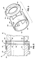
- FIGs. 1 and 4 show the overall arrangement of a tube coupling assembly formed in accordance with the present invention and comprising first and second coupling components 12 and 14 which are held in aligned and connected position by threaded nut members 16 and 18.
- each of the coupling members 12, 14 comprises a substantially cylindrical main body 20 with a through-flow passage 22 extending axially therethrough.
- a radially extending flange 24 is formed adjacent an enlarged end 26 which has a sealing end face 28.
- each of the end faces 28 includes a circumferentially extending bead or rib 30.
- the bead or rib 30 acts as a sealing surface for engagement with a metal gasket 32.
- the nut member 16 has a counterbored section 34 which is sized to closely receive the flange 24 of the coupling component 12 to align the coupling component 12 and to apply the necessary axially directed forces.
- a sleeve-like, substantially cylindrical anti-torque member 40 positioned between a radially extending shoulder 36 on nut member 18 and the flange 24 of coupling component 14 is a sleeve-like, substantially cylindrical anti-torque member 40.
- the anti-torque member is described more fully in EP-A-0439328.
- the anti-torque member 40 is best illustrated in Fig. 4.
- the member 40 has a stepped diameter, axially extending opening 42 which includes a first section 42a which is sized so as to freely receive the cylindrical portion 20 of the coupling component 14. This relationship is illustrated in Fig. 1.
- the second section 42b of the opening 42 is sized so as to closely receive the flange 24 of coupling component 14.
- the shoulder face 44 between the cylindrical sections 42a and 44b is arranged to engage the flange 24 of coupling component 14 in the manner shown to apply axial forces thereto.
- the exterior cylindrical section 46 of anti-torque member 40 is sized so as to be freely and closely received within the cylindrical interior 18a of nut member 18.
- the anti-torque member 40 further has a pair of diametrically opposed, axially extending fingers or tabs 50.
- a corresponding pair of similar tabs 52 extends from the inner end of the nut member 16.
- a coil spring member 54 is preferably provided about the reduced diameter right-hand end of the anti-torque member 40.
- This compression spring 54 assists in assembly and make-up of the coupling. In particular, it maintains the anti-torque member 40 in an axially outwardly biased position relative to the nut member 18 such that the tabs 50 are clearly visible to the assembler so that they can be properly engaged with the tabs 52 as the nut members 16, 18 are threaded together at the start of the make-up operation.
- the presence of the anti-torque member 40 tends to increase the overall size of the coupling or to reduce the space available in the interior for use of gasket retainers if such are desired.
- the typical prior gasket retainers as shown, for example in US-A-4,552,389; US-A-4,650,277; and US-A-4,838,583 are such that, when used, they require a different diameter gasket than those gaskets used when a retainer is not present.
- the gasket and retainer assembly of the present invention allows the use of a gasket retainer when the anti-torque member is used.
- the gasket retainer of the coupling according to the invention uses a gasket which can function adequately also when a retainer is not used.
- the outer diameter of the gasket can be the same as is required for non-retainer use.
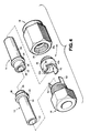
- the gasket and retainer assembly of the coupling according to the invention comprises a sleeve-like cylindrical retainer 60 which has a main circumferentially continuous body section 62 which has an inner diameter that is only slightly larger than the diameter of the end section 26 of the coupling component 12. As illustrated in Fig. 2, this allows the retainer 60 to be received on the end of the coupling component 12 in surrounding relationship to the sealing face 28.
- the retainer 60 is arranged to be frictionally engaged with and retained on the end portion 26 by, for example, a pair of detent or bead-like deformations 64 which are formed at diametrically opposite sides of the body portion 62 to resiliently and frictionally engage the outer surface of section 26 of the coupling component 12.
- the body 62 of the retainer 60 is preferably formed from a resilient metal.
- the retainer 60 is formed from stainless steel with a wall thickness in the range of about 0.10mm to about 0.20mm (about 0.004 inch to about 0.008 inch). The sleeve-like body 62 of the retainer 60 can thus elastically deflect radially to assume a non-circular shape to produce gripping by the detents 64.
- the gasket 32 and the retainer 60 are a unitary assembly which facilitate installation and mounting of the gasket in position on the coupling components 12 or 14. In addition, the relationship between the gasket 32 and retainer 60 remains constant irrespective of removal or replacement of the assembly.
Landscapes
- Engineering & Computer Science (AREA)
- General Engineering & Computer Science (AREA)
- Mechanical Engineering (AREA)
- Joints With Pressure Members (AREA)
- Gasket Seals (AREA)
- Non-Disconnectible Joints And Screw-Threaded Joints (AREA)
Abstract
Description
- The invention relates to fluid couplings and is applicable, to a tube coupling particularly suited for use in high vacuum and pressure systems.
- One type of coupling which has achieved widespread acceptance comprises a pair of coupling components having longitudinally extending fluid passageways and terminating in mating end faces each constituting a sealing face which is provided with an annular rib or sealing bead which extends outwardly and about the associated end. With the components oriented in face-to-face relationship, an annular metal sealing gasket is interposed between the sealing beads. Threaded nuts act to drive the coupling components together to cause the annular ribs to sealingly engage the gasket.
- In order to properly locate the sealing gasket relative to the end faces, various gasket retainers have been proposed in the prior art. These retainers are shown, for example, in US-A-4,552,389; US-A-4,650,227; and US-A-4,838,583. The gasket retainers have been very satisfactory for their intended purpose. Recently, however, a modified form of the basic coupling design (EP-A-0439328, published on 31st July 1991) has presented difficulties with respect to the prior gasket retainers. In this recent coupling design, a separate anti-torque member is mounted inside the nut members in surrounding relationship with the ends of the sealing face. This anti-torque member acts to prevent transmission of torque to the coupling components, the sealing washer, or the associated piping during tightening of the nut members.
- The presence of the anti-torque member can have the effect of increasing the overall external dimensions of the coupling. In an effort at keeping these external dimensions small, the spacings between the components is reduced as much as possible. As a consequence, it is somewhat difficult to use the more conventional gasket retaining devices. Further, with the conventional gasket retainer, it is necessary for the gasket to have a smaller outer diameter than the gasket required when a retainer is not used. Thus, two different gaskets must be stocked.
- An object of the invention is to provide a gasket and retainer assembly which overcomes the noted problems and provides a gasket retainer which takes up only a small amount of space in the coupling assembly. Moreover, the gasket and retainer assembly may be such that the same gasket design is capable of use either with or without an associated retainer. Thus, only one gasket needs to be stocked to satisfy both retainer and non-retainer situations.
- One object of the present invention is the provision of a tube coupling of the general type described wherein the gasket and gasket retainer assembly is a highly simplified structure which can be fitted within an extremely small space within the coupling assembly.
- A further object is the provision of a gasket retainer assembly of the type described wherein the gasket itself can be used either with or without a retainer, thereby limiting the need for gaskets of different sizes as would have been required with the prior gasket retainer assemblies.
- Yet another, and more limited object of the invention, is the provision of a gasket retainer assembly wherein the gasket retainer engages radially inward of the maximum outer periphery of the gasket.
- In particular, the invention comprises a fluid coupling of the type having first and second generally cylindrical coupling components including fluid passageways extending longitudinally therethrough. The components have opposed radial inface with sealing ribs extending axially therefrom towards each other with an annular sealing gasket interposed therebetween. The coupling further includes nut members for moving the components into a closely spaced substantially craxial relationship such that the sealing ribs sealingly engage opposite face areas of the gasket. A retainer device maintains the gasket in a predetermined located position relative to the end face of one of the components in a substantially coaxial relationship therewith. According to the invention, the retainer has a generally sleeve-like body which defines a retained portion closely received over the one component at an area spaced axially rearward from the associated radial end face. Also, according to the invention, the retainer has a plurality of axially extending fingers circumferentially spaced about the retaining portion and extending axially outward beyond the associated radial end face. Preferably, the diameter of the outer periphery of the sealing gasket is at least slightly greater than the inner diameter of the sleeve-like body. Also, according to the invention recesses are formed in the outer periphery. The recesses are located and sized to closely receive the axially extending leg portions to thus hold the gasket in aligned relationship with the end face.
- Because of the relationship between the gasket and the gasket retainer, the outer diameter of the gasket can be sized to closely correspond to the inner diameter of the nut members so that centering of the gasket and the nut member can be achieved even when a gasket retainer is not used.
- In accordance with another more limited aspect of the invention, the gasket retainer and the gasket are maintained in a unitary assembled position by having the ends of the fingers provided with a catch means for preventing the gasket from being axially removed therefrom. This permits the gasket and the retainer to be handled as a single unit during installation and removal.
- Preferably, the retainer also has detents for frictionally engaging the associated coupling components so that the gasket and retainer are frictionally retained thereon. It is also contemplated that, if desired, catch means can comprise inwardly bent tab portions at the free ends of the fingers.
- In the preferred embodiment, the retainer is formed from a relatively thin metal having a relatively high degree of resiliency. The frictional detents can thus resiliently engage the coupling body as a result of elastic deformation of the sleeve-like body of the retainer. No special spring latches or similar connecting structure is required.
- The invention is further described, by way of example, with reference to the accompanying drawings, wherein:
- Fig. 1 is a longitudinal sectional view taken through a coupling assembly formed in accordance with a preferred embodiment of the invention;
- Fig. 2 is a greater enlarged view of the circled area of Fig. 1;
- Fig. 3 is an exploded perspective view of the gasket and gasket retainer elements; and
- Fig. 4 is an exploded pictorial view of all elements of the coupling except for the gasket and gasket retainer.
- Referring to the drawings Figs. 1 and 4 show the overall arrangement of a tube coupling assembly formed in accordance with the present invention and comprising first and
second coupling components nut members - In the preferred embodiment, the
coupling components nut members coupling members main body 20 with a through-flow passage 22 extending axially therethrough. A radially extendingflange 24 is formed adjacent an enlargedend 26 which has a sealingend face 28. Referring to Fig. 2, each of theend faces 28 includes a circumferentially extending bead orrib 30. The bead orrib 30 acts as a sealing surface for engagement with ametal gasket 32. The particular preferred details of therib 30 are described more fully in European Patent Application No. 91 305879.8. - By tightening the threaded
nut member coupling components ribs 30 to engage into the opposite faces of theannular metal gasket 32. Thenut member 16 has acounterbored section 34 which is sized to closely receive theflange 24 of thecoupling component 12 to align thecoupling component 12 and to apply the necessary axially directed forces. Similarly, positioned between a radially extendingshoulder 36 onnut member 18 and theflange 24 ofcoupling component 14 is a sleeve-like, substantially cylindricalanti-torque member 40. The anti-torque member is described more fully in EP-A-0439328. Theanti-torque member 40 is best illustrated in Fig. 4. It is arranged to prevent torque from being applied from thenut members coupling components gasket 32. Themember 40 has a stepped diameter, axially extendingopening 42 which includes afirst section 42a which is sized so as to freely receive thecylindrical portion 20 of thecoupling component 14. This relationship is illustrated in Fig. 1. Thesecond section 42b of theopening 42 is sized so as to closely receive theflange 24 ofcoupling component 14. The shoulder face 44 between thecylindrical sections 42a and 44b is arranged to engage theflange 24 ofcoupling component 14 in the manner shown to apply axial forces thereto. The exteriorcylindrical section 46 ofanti-torque member 40 is sized so as to be freely and closely received within thecylindrical interior 18a ofnut member 18. - As best seen in Fig. 4, the
anti-torque member 40 further has a pair of diametrically opposed, axially extending fingers ortabs 50. A corresponding pair ofsimilar tabs 52 extends from the inner end of thenut member 16. Thesetabs nut members coupling members tabs nut member 16 and the anti-torque member 4 are located together in a manner which does not allow torque to be transmitted to thecoupling components - As described more fully in the aforementioned EP-A-0439328, a
coil spring member 54 is preferably provided about the reduced diameter right-hand end of theanti-torque member 40. Thiscompression spring 54 assists in assembly and make-up of the coupling. In particular, it maintains theanti-torque member 40 in an axially outwardly biased position relative to thenut member 18 such that thetabs 50 are clearly visible to the assembler so that they can be properly engaged with thetabs 52 as thenut members - As previously discussed, the presence of the
anti-torque member 40 tends to increase the overall size of the coupling or to reduce the space available in the interior for use of gasket retainers if such are desired. The typical prior gasket retainers as shown, for example in US-A-4,552,389; US-A-4,650,277; and US-A-4,838,583 are such that, when used, they require a different diameter gasket than those gaskets used when a retainer is not present. The gasket and retainer assembly of the present invention allows the use of a gasket retainer when the anti-torque member is used. Also, the gasket retainer of the coupling according to the invention uses a gasket which can function adequately also when a retainer is not used. That is, the outer diameter of the gasket can be the same as is required for non-retainer use. As specifically shown in Figs. 2 and 3, the gasket and retainer assembly of the coupling according to the invention comprises a sleeve-likecylindrical retainer 60 which has a main circumferentiallycontinuous body section 62 which has an inner diameter that is only slightly larger than the diameter of theend section 26 of thecoupling component 12. As illustrated in Fig. 2, this allows theretainer 60 to be received on the end of thecoupling component 12 in surrounding relationship to the sealingface 28. Preferably, theretainer 60 is arranged to be frictionally engaged with and retained on theend portion 26 by, for example, a pair of detent or bead-like deformations 64 which are formed at diametrically opposite sides of thebody portion 62 to resiliently and frictionally engage the outer surface ofsection 26 of thecoupling component 12. - To assure proper gripping by the detent or bead-
like deformations 64, thebody 62 of theretainer 60 is preferably formed from a resilient metal. For example, in the present embodiment, theretainer 60 is formed from stainless steel with a wall thickness in the range of about 0.10mm to about 0.20mm (about 0.004 inch to about 0.008 inch). The sleeve-like body 62 of theretainer 60 can thus elastically deflect radially to assume a non-circular shape to produce gripping by thedetents 64. - Extending axially from the right-hand end of body portion 62 (as viewed in Figs. 2 and 3) is a plurality of fingers or tab-
like formations 66. Corresponding grooves orslots 68 are formed about the periphery of thegasket 32. The width and location of therecesses 68 are such as to exactly correspond to the width and location of thefingers 66. Additionally, the major diameter of thegasket 32 is preferably substantially equal to the outer diameter of thebody section 62 of thegasket retainer 60. Thus, when thegasket 32 is positioned in the assembled relationship on thefingers 66, the tips or outer end portions of thefingers 66 can be deflected radially inward to thus hold thegasket 32 in position on theretainer 60. Thus, thegasket 32 and theretainer 60 are a unitary assembly which facilitate installation and mounting of the gasket in position on thecoupling components gasket 32 andretainer 60 remains constant irrespective of removal or replacement of the assembly. - The invention has been described with reference to the preferred and alternative embodiment. Modifications and alterations are included in so far as they come within the scope of the claims.
Claims (14)
- A fluid coupling comprising first and second substantially cylindrical coupling components (12,14) having fluid passageways (22) extending longitudinally thereof and having opposed radial end faces (28) including sealing ribs (30) extending axially therefrom towards each other with an annular sealing gasket (32) interposed therebetween, nut means (16,18) for moving said components (12,14) into a closely-spaced substantially coaxial relationship such that said sealing ribs (30) sealingly engage opposite face areas of said gasket (32), and a retainer (60) for maintaining said gasket (32) in a predetermined located position relative to the end face of one (12) of said components in a substantially coaxial relationship therewith, characterised in that said retainer (60) has a sleeve-like body (62) defining a retaining portion closely received over said one component (16) at an area thereof spaced axially rearward from the associated radial end face (30), and in that said retainer (30) also has a plurality of axially extending fingers (66) circumferentially spaced about said sleeve-like body (62) and extending axially outwardly beyond said associated radial end face (30), and said annular sealing gasket (32) has recesses (68) in its outer periphery (of a diameter at least slightly greater than the inner diameter of said sleeve-like body (62) with recesses (68) formed in said outer periphery), said recesses (68) receiving said axially extending fingers (66), whereby said gasket (32) is maintained in aligned relationship with said end face (30).
- A fluid coupling as claimed in claim 1, in which the diameter of the outer periphery of said sealing gasket (32) is at least slightly greater than the inner diameter of said sleeve-like body (62).
- A fluid coupling as claimed in claim 2, wherein the maximum diameter of said gasket (60) is substantially equal to the maximum outer diameter of said sleeve-like body (62).
- A fluid coupling as claimed in claim 1, 2 or 3, wherein said sleeve-like body (62) is circumferentially continuous and includes detents (64) for frictionally engaging said one component (12) at circumferentially spaced locations.
- A fluid coupling as claimed in claim 4, wherein said cylindrical body (62) is formed of a relatively thin and resilient metal capable of elastically deforming in the radial direction to produce frictional engagement of said detents (60) with said one component (12).
- A fluid coupling as claimed in any of claims 1 to 5, wherein said fingers (66) are provided with catch means for preventing said gasket (32) from being removed axially therefrom.
- A fluid coupling as claimed in claim 6, wherein the free ends of said fingers (66) extend radially inwardly to form said catch means.
- A fluid coupling as claimed in any of claims 1 to 7, wherein said fingers (66) are aligned with said sleeve-like body (62).
- A fluid coupling as claimed in claim 8 wherein said fingers (66) are an extension of said sleeve-like body (62) and are integral therewith.
- A fluid coupling as claimed in any of claims 1 to 9, wherein said fingers (66) are located at uniformly spaced locations about said sleeve-like body (62).
- A fluid coupling as claimed in any of claims 1 to 10, wherein said fingers (66) are each of uniform width and wherein said recesses (68) are sized to closely receive said fingers (66).
- A fluid coupling as claimed in any of claims 1 to 11, wherein said recesses (68) are grooves which open radially outwardly.
- A fluid coupling as claimed in any of claims 1 to 12, wherein there are at least three of said recesses (68).
- A fluid coupling comprising first and second substantially cylindrical coupling components (12,14) having fluid passageways (22) extending longitudinally thereof and having opposed radial end faces (28) including sealing beads (30) extending axially therefrom toward each other with an annular sealing gasket (32) interposed therebetween, means for moving said components (12,14) into a closely-spaced substantially coaxial relationship such that said sealing beads (30) sealingly engage opposite face areas of said gasket (32), and a retainer (60) for maintaining said gasket (32) in a predetermined located position relative to the end face of one (12) of said components in a substantially coaxial relationship therewith, characterised in that said retainer (60) has a substantially cylindrical body (62) including a retaining portion of sleeve-like configuration closely received over said one component (12) at an area thereof spaced axially rearward from the associated radial end face (30), and in that said retainer (30) also has a plurality of axially extending leg portions (66) circumferentially spaced about said cylindrical body (62) and extending axially outward about said associated radial end face (30) and said annular sealing gasket (32) has an outer periphery with recesses (68) formed therein and receiving said axially extending leg portions (66) to maintain said gasket (32) in aligned relationship with said end face.
Applications Claiming Priority (2)
| Application Number | Priority Date | Filing Date | Title |
|---|---|---|---|
| US602752 | 1990-10-24 | ||
| US07/602,752 US5163721A (en) | 1990-10-24 | 1990-10-24 | Fluid coupling with gasket retainer having interlocking portions |
Publications (3)
| Publication Number | Publication Date |
|---|---|
| EP0482865A2 true EP0482865A2 (en) | 1992-04-29 |
| EP0482865A3 EP0482865A3 (en) | 1992-10-07 |
| EP0482865B1 EP0482865B1 (en) | 1995-05-03 |
Family
ID=24412662
Family Applications (1)
| Application Number | Title | Priority Date | Filing Date |
|---|---|---|---|
| EP91309717A Expired - Lifetime EP0482865B1 (en) | 1990-10-24 | 1991-10-21 | Fluid coupling |
Country Status (7)
| Country | Link |
|---|---|
| US (1) | US5163721A (en) |
| EP (1) | EP0482865B1 (en) |
| JP (1) | JPH04262187A (en) |
| KR (1) | KR0173473B1 (en) |
| AT (1) | ATE122132T1 (en) |
| CA (1) | CA2054076A1 (en) |
| DE (1) | DE69109440T2 (en) |
Cited By (6)
| Publication number | Priority date | Publication date | Assignee | Title |
|---|---|---|---|---|
| EP0566980A1 (en) * | 1992-04-20 | 1993-10-27 | Fujikin Incorporated | Pipe joint and retainer for use in pipe joint |
| US7207605B2 (en) * | 1997-06-16 | 2007-04-24 | Swagelok Company | Tube coupling |
| CN101956751A (en) * | 2010-06-08 | 2011-01-26 | 昆山新莱洁净应用材料股份有限公司 | Elastic washer for pipe connection and locking connection pipe using same |
| CN105003552A (en) * | 2015-07-23 | 2015-10-28 | 成都广迈科技有限公司 | Electrical control bidirectional bearing |
| EP3421856A1 (en) * | 2017-06-29 | 2019-01-02 | SERTO Holding AG | Pipe connection |
| EP4067719A1 (en) * | 2021-03-29 | 2022-10-05 | ALFA LAVAL OLMI S.p.A. | Improved sealing device for bores of a heat exchanger |
Families Citing this family (41)
| Publication number | Priority date | Publication date | Assignee | Title |
|---|---|---|---|---|
| US5222747A (en) * | 1991-05-01 | 1993-06-29 | General Components, Inc. | Fitting with overtightening prevention gasket |
| US5505464A (en) * | 1989-08-11 | 1996-04-09 | General Components, Inc. | Minimum dead volume fitting |
| JP2540559Y2 (en) * | 1991-05-20 | 1997-07-09 | 清原 まさ子 | Pipe Fitting Retainer |
| US5366261A (en) * | 1992-04-27 | 1994-11-22 | Fujikin Incorporated | Pipe joint with a gasket retainer |
| US5306052A (en) * | 1992-12-15 | 1994-04-26 | Megushion Kevin D | Tubing union with a torque transfer fitting |
| NO307625B1 (en) * | 1994-08-03 | 2000-05-02 | Norsk Hydro As | Rudder shot for joining two rudders with longitudinal wires in the rudder wall |
| US5782500A (en) * | 1995-05-26 | 1998-07-21 | Mate; Robert James | Passageway aligned coupling and process |
| US5673946A (en) * | 1995-07-07 | 1997-10-07 | Ewal Manufacturing Co., Inc. | Gasket assembly for a fluid coupling |
| US5681064A (en) * | 1995-07-07 | 1997-10-28 | Ewal Manufacturing Co., Inc. | Gasket retainer |
| JP3627083B2 (en) * | 1996-10-15 | 2005-03-09 | 株式会社フジキン | Retainer for fluid coupling |
| US5829796A (en) * | 1997-03-11 | 1998-11-03 | Robinson; Eric R. | Protection of sealing surfaces of metal face seals in tubing fittings |
| US6308994B1 (en) * | 1997-04-08 | 2001-10-30 | Swagelok Company | Fluid fitting with torque suppression arrangement |
| JP3965512B2 (en) * | 1998-03-31 | 2007-08-29 | 株式会社フジキン | Gasket retainer used in fluid coupling and fluid coupling |
| DE19846475A1 (en) * | 1998-10-09 | 2000-04-13 | Fischer Georg Rohrleitung | Gasket |
| CH693151A5 (en) * | 1998-10-29 | 2003-03-14 | Pma Ag | Connecting and coupling piece for corrugated tubes. |
| US6347729B1 (en) | 2000-09-28 | 2002-02-19 | Chapin Manufacturing, Inc. | Hose coupling apparatus for sprayer unit |
| GB2374887B (en) | 2001-04-27 | 2003-12-17 | Schlumberger Holdings | Method and apparatus for orienting perforating devices |
| US7114564B2 (en) * | 2001-04-27 | 2006-10-03 | Schlumberger Technology Corporation | Method and apparatus for orienting perforating devices |
| US6708985B1 (en) * | 2002-06-28 | 2004-03-23 | Michael Doyle | Ring seal and retainer assembly |
| US7364166B2 (en) * | 2003-01-24 | 2008-04-29 | Applied Engineered Surfaces, Inc. | Seal and retainer for a fluid connection |
| US20050275222A1 (en) * | 2004-06-14 | 2005-12-15 | Yoakam John A | Gasket for a fluid connection |
| US20070045968A1 (en) * | 2005-08-31 | 2007-03-01 | Integra Companies, Inc. | Pipe gasket |
| US20080012325A1 (en) * | 2005-09-21 | 2008-01-17 | Honeywell International Inc. | Fill tube-flange assembly for ring laser gyroscope block |
| US20080035297A1 (en) * | 2006-08-11 | 2008-02-14 | Husky Injection Molding Systems Ltd. | Seal of a metal molding system |
| US7686351B2 (en) * | 2007-07-27 | 2010-03-30 | Air Products And Chemicals, Inc. | Soft insert gasket |
| DE102008044704B4 (en) * | 2007-08-28 | 2011-05-26 | Line Up Handels Gmbh | Apparatus and method for providing propulsion clutches |
| US7950700B2 (en) * | 2008-03-13 | 2011-05-31 | Paw Bioscience Products, Inc. | Connector assembly for sterile connectors |
| JP5614793B2 (en) * | 2008-12-12 | 2014-10-29 | 矢崎総業株式会社 | Structure for preventing incorrect assembly of packing |
| WO2011004935A1 (en) * | 2009-07-08 | 2011-01-13 | (주)스톰테크 | Tube coupling |
| US20110133415A1 (en) * | 2009-12-07 | 2011-06-09 | Kim Ngoc Vu | Ring seal and retainer assembly |
| WO2012003887A1 (en) * | 2010-07-09 | 2012-01-12 | Dresser Wayne Ab | Connection arrangement and method for assembling the same |
| US9074686B2 (en) | 2010-12-06 | 2015-07-07 | Microflex Technologies Llc | Ring seal retainer assembly and methods |
| JP5875306B2 (en) * | 2011-09-22 | 2016-03-02 | 東京エレクトロン株式会社 | Pipe fitting |
| US9453600B2 (en) * | 2012-05-15 | 2016-09-27 | Parker-Hannifin Corporation | Extreme temperature device for flat face seal fitting |
| JP5988822B2 (en) * | 2012-10-19 | 2016-09-07 | 株式会社フジキン | Pipe fitting |
| WO2015109382A1 (en) * | 2014-01-21 | 2015-07-30 | Halliburton Energy Services, Inc. | Locking nut with a directional coupling mechanism |
| CN106104131B (en) * | 2014-02-27 | 2018-05-29 | 桑杜科技有限公司 | face seal fitting |
| TWI736124B (en) | 2014-04-17 | 2021-08-11 | 新加坡商肯發系統私人有限公司 | Ring-shaped gasket for sealingly joining opposed fluid conduit ports and method of forming a high purity fluid joint |
| US10111364B2 (en) * | 2015-05-20 | 2018-10-23 | International Business Machines Corporation | Coupling assemblies for connecting fluid-carrying components |
| CN105065470B (en) * | 2015-07-23 | 2018-07-10 | 衢州熊妮妮计算机科技有限公司 | A kind of two-way bearing of electric limiting |
| US11414965B2 (en) | 2018-02-27 | 2022-08-16 | Schlumberger Technology Corporation | Rotating loading tube and angled shaped charges for oriented perforating |
Citations (6)
| Publication number | Priority date | Publication date | Assignee | Title |
|---|---|---|---|---|
| US682873A (en) * | 1900-06-23 | 1901-09-17 | Francisco D Joy | Metal hose-coupling and washer. |
| US3427053A (en) * | 1966-12-22 | 1969-02-11 | Jerald V Dunlap | Coupling and seal apparatus for hoses and other tubular conduits for fluids |
| US4552389A (en) * | 1982-08-23 | 1985-11-12 | Cajon Company | Fluid coupling |
| US4650227A (en) * | 1982-08-23 | 1987-03-17 | Cajon Company | Fluid coupling |
| US4838583A (en) * | 1982-08-23 | 1989-06-13 | Cajon Company | Fluid coupling |
| EP0439328A2 (en) * | 1990-01-23 | 1991-07-31 | Cajon Company | Tube coupling |
Family Cites Families (12)
| Publication number | Priority date | Publication date | Assignee | Title |
|---|---|---|---|---|
| US748546A (en) * | 1903-04-17 | 1903-12-29 | Ralph Ernest Vail | Expansion-joint. |
| US954549A (en) * | 1907-02-19 | 1910-04-12 | Joseph C Hartwell | Pipe-coupling. |
| US1027565A (en) * | 1911-07-11 | 1912-05-28 | Jonathan Wade Ramage | Gasket-retainer. |
| US1137382A (en) * | 1914-05-12 | 1915-04-27 | Walter Riley Calvert | Hose-washer. |
| US1133320A (en) * | 1914-11-16 | 1915-03-30 | George I Rockwood | Packing-ring for pipe-fittings. |
| US1562982A (en) * | 1925-04-22 | 1925-11-24 | Haines Jones & Cadbury Inc | Nozzle connection |
| US2782385A (en) * | 1954-06-08 | 1957-02-19 | Colber Corp | Electronic tuner |
| US3262722A (en) * | 1964-11-19 | 1966-07-26 | United Aircraft Prod | Coupling having an o-ring retainer |
| US3709528A (en) * | 1971-04-16 | 1973-01-09 | Foster Mfg Co Inc | Hose coupling |
| US4571133A (en) * | 1984-07-23 | 1986-02-18 | General Motors Corporation | Loading washer assembly |
| US4665960A (en) * | 1985-03-04 | 1987-05-19 | Cajon Company | Coded coupling |
| JPS6275188A (en) * | 1985-09-30 | 1987-04-07 | 三興工業株式会社 | Superfine piping joint |
-
1990
- 1990-10-24 US US07/602,752 patent/US5163721A/en not_active Expired - Lifetime
-
1991
- 1991-10-21 DE DE69109440T patent/DE69109440T2/en not_active Expired - Fee Related
- 1991-10-21 EP EP91309717A patent/EP0482865B1/en not_active Expired - Lifetime
- 1991-10-21 AT AT91309717T patent/ATE122132T1/en not_active IP Right Cessation
- 1991-10-23 CA CA002054076A patent/CA2054076A1/en not_active Abandoned
- 1991-10-24 KR KR1019910018759A patent/KR0173473B1/en not_active IP Right Cessation
- 1991-10-24 JP JP3277603A patent/JPH04262187A/en active Pending
Patent Citations (7)
| Publication number | Priority date | Publication date | Assignee | Title |
|---|---|---|---|---|
| US682873A (en) * | 1900-06-23 | 1901-09-17 | Francisco D Joy | Metal hose-coupling and washer. |
| US3427053A (en) * | 1966-12-22 | 1969-02-11 | Jerald V Dunlap | Coupling and seal apparatus for hoses and other tubular conduits for fluids |
| US4552389A (en) * | 1982-08-23 | 1985-11-12 | Cajon Company | Fluid coupling |
| US4650227A (en) * | 1982-08-23 | 1987-03-17 | Cajon Company | Fluid coupling |
| US4838583A (en) * | 1982-08-23 | 1989-06-13 | Cajon Company | Fluid coupling |
| US4650227B1 (en) * | 1982-08-23 | 2000-11-28 | Cajon Co | Fluid coupling |
| EP0439328A2 (en) * | 1990-01-23 | 1991-07-31 | Cajon Company | Tube coupling |
Cited By (11)
| Publication number | Priority date | Publication date | Assignee | Title |
|---|---|---|---|---|
| EP0566980A1 (en) * | 1992-04-20 | 1993-10-27 | Fujikin Incorporated | Pipe joint and retainer for use in pipe joint |
| US5340170A (en) * | 1992-04-20 | 1994-08-23 | Fujikin Incorporated | Pipe joint and gasket retainer for use in pipe joint |
| US7207605B2 (en) * | 1997-06-16 | 2007-04-24 | Swagelok Company | Tube coupling |
| CN101956751A (en) * | 2010-06-08 | 2011-01-26 | 昆山新莱洁净应用材料股份有限公司 | Elastic washer for pipe connection and locking connection pipe using same |
| CN101956751B (en) * | 2010-06-08 | 2013-03-20 | 昆山新莱洁净应用材料股份有限公司 | Elastic washer for pipe connection and locking connection pipe using same |
| CN105003552A (en) * | 2015-07-23 | 2015-10-28 | 成都广迈科技有限公司 | Electrical control bidirectional bearing |
| CN105003552B (en) * | 2015-07-23 | 2018-03-06 | 张露丹 | A kind of two-way bearing of electrical control |
| EP3421856A1 (en) * | 2017-06-29 | 2019-01-02 | SERTO Holding AG | Pipe connection |
| EP4119829A1 (en) | 2017-06-29 | 2023-01-18 | SERTO Holding AG | Pipe connection |
| EP4067719A1 (en) * | 2021-03-29 | 2022-10-05 | ALFA LAVAL OLMI S.p.A. | Improved sealing device for bores of a heat exchanger |
| WO2022207336A1 (en) * | 2021-03-29 | 2022-10-06 | Alfa Laval Olmi S.P.A | Improved sealing device for bores of a heat exchanger |
Also Published As
| Publication number | Publication date |
|---|---|
| KR0173473B1 (en) | 1999-02-18 |
| ATE122132T1 (en) | 1995-05-15 |
| EP0482865A3 (en) | 1992-10-07 |
| US5163721A (en) | 1992-11-17 |
| CA2054076A1 (en) | 1992-04-25 |
| DE69109440T2 (en) | 1995-09-14 |
| JPH04262187A (en) | 1992-09-17 |
| KR930008361A (en) | 1993-05-21 |
| EP0482865B1 (en) | 1995-05-03 |
| DE69109440D1 (en) | 1995-06-08 |
Similar Documents
| Publication | Publication Date | Title |
|---|---|---|
| EP0482865B1 (en) | Fluid coupling | |
| EP0306126B1 (en) | Quick connect coupling | |
| CA1291186C (en) | Fluid coupling | |
| EP0937935B1 (en) | Tubular coupling | |
| EP0796405B1 (en) | Squeeze-to-release quick connector with snap-in retainer | |
| US4063760A (en) | Quick connect coupling | |
| US5303963A (en) | Tube coupling with secondary retainer clip | |
| EP0645572B1 (en) | Anti-rotation locking device for preventing separation of coupling nuts from fluid lines | |
| US4552389A (en) | Fluid coupling | |
| US5423580A (en) | Fluid coupling with gasket retainer | |
| US5979910A (en) | Retainer for use in fluid couplings | |
| EP0193271A1 (en) | Push-in connect fitting | |
| EP0567924A1 (en) | Pipe joint | |
| AU2017266869B2 (en) | Fitting having tabbed retainer and observation apertures | |
| US4114898A (en) | Oil seal with permanently deformable locking member | |
| JPH02266167A (en) | Sealing device | |
| EP0564637A4 (en) | ||
| EP0099136A1 (en) | Pressed-in anti-rotation lugs for mechanical face seals | |
| EP0568032B1 (en) | Coupling for metal tubes | |
| US6106028A (en) | Snap-fastening coupling for a fluid duct, in particular for a motor vehicle | |
| US3618990A (en) | Tube coupling | |
| GB2123106A (en) | Conduit end fitting | |
| US6685234B2 (en) | Fluid fitting with torque suppression arrangement | |
| GB2125501A (en) | Conduit end fitting | |
| US5000489A (en) | Service saddle |
Legal Events
| Date | Code | Title | Description |
|---|---|---|---|
| PUAI | Public reference made under article 153(3) epc to a published international application that has entered the european phase |
Free format text: ORIGINAL CODE: 0009012 |
|
| AK | Designated contracting states |
Kind code of ref document: A2 Designated state(s): AT BE CH DE FR GB IT LI NL |
|
| PUAL | Search report despatched |
Free format text: ORIGINAL CODE: 0009013 |
|
| AK | Designated contracting states |
Kind code of ref document: A3 Designated state(s): AT BE CH DE FR GB IT LI NL |
|
| 17P | Request for examination filed |
Effective date: 19930517 |
|
| 17Q | First examination report despatched |
Effective date: 19940916 |
|
| GRAA | (expected) grant |
Free format text: ORIGINAL CODE: 0009210 |
|
| AK | Designated contracting states |
Kind code of ref document: B1 Designated state(s): AT BE CH DE FR GB IT LI NL |
|
| REF | Corresponds to: |
Ref document number: 122132 Country of ref document: AT Date of ref document: 19950515 Kind code of ref document: T |
|
| ET | Fr: translation filed | ||
| REF | Corresponds to: |
Ref document number: 69109440 Country of ref document: DE Date of ref document: 19950608 |
|
| ITF | It: translation for a ep patent filed |
Owner name: ING. C. GREGORJ S.P.A. |
|
| PLBE | No opposition filed within time limit |
Free format text: ORIGINAL CODE: 0009261 |
|
| STAA | Information on the status of an ep patent application or granted ep patent |
Free format text: STATUS: NO OPPOSITION FILED WITHIN TIME LIMIT |
|
| 26N | No opposition filed | ||
| PGFP | Annual fee paid to national office [announced via postgrant information from national office to epo] |
Ref country code: NL Payment date: 19980914 Year of fee payment: 8 |
|
| PGFP | Annual fee paid to national office [announced via postgrant information from national office to epo] |
Ref country code: AT Payment date: 19980917 Year of fee payment: 8 |
|
| PGFP | Annual fee paid to national office [announced via postgrant information from national office to epo] |
Ref country code: GB Payment date: 19981001 Year of fee payment: 8 |
|
| PGFP | Annual fee paid to national office [announced via postgrant information from national office to epo] |
Ref country code: FR Payment date: 19981006 Year of fee payment: 8 |
|
| PGFP | Annual fee paid to national office [announced via postgrant information from national office to epo] |
Ref country code: DE Payment date: 19981028 Year of fee payment: 8 |
|
| PGFP | Annual fee paid to national office [announced via postgrant information from national office to epo] |
Ref country code: BE Payment date: 19981112 Year of fee payment: 8 |
|
| PGFP | Annual fee paid to national office [announced via postgrant information from national office to epo] |
Ref country code: CH Payment date: 19981218 Year of fee payment: 8 |
|
| PG25 | Lapsed in a contracting state [announced via postgrant information from national office to epo] |
Ref country code: GB Free format text: LAPSE BECAUSE OF NON-PAYMENT OF DUE FEES Effective date: 19991021 Ref country code: AT Free format text: LAPSE BECAUSE OF NON-PAYMENT OF DUE FEES Effective date: 19991021 |
|
| PG25 | Lapsed in a contracting state [announced via postgrant information from national office to epo] |
Ref country code: LI Free format text: LAPSE BECAUSE OF NON-PAYMENT OF DUE FEES Effective date: 19991031 Ref country code: CH Free format text: LAPSE BECAUSE OF NON-PAYMENT OF DUE FEES Effective date: 19991031 Ref country code: BE Free format text: LAPSE BECAUSE OF NON-PAYMENT OF DUE FEES Effective date: 19991031 |
|
| BERE | Be: lapsed |
Owner name: CAJON CY Effective date: 19991031 |
|
| PG25 | Lapsed in a contracting state [announced via postgrant information from national office to epo] |
Ref country code: NL Free format text: LAPSE BECAUSE OF NON-PAYMENT OF DUE FEES Effective date: 20000501 |
|
| GBPC | Gb: european patent ceased through non-payment of renewal fee |
Effective date: 19991021 |
|
| REG | Reference to a national code |
Ref country code: CH Ref legal event code: PL |
|
| PG25 | Lapsed in a contracting state [announced via postgrant information from national office to epo] |
Ref country code: FR Free format text: LAPSE BECAUSE OF NON-PAYMENT OF DUE FEES Effective date: 20000630 |
|
| NLV4 | Nl: lapsed or anulled due to non-payment of the annual fee |
Effective date: 20000501 |
|
| PG25 | Lapsed in a contracting state [announced via postgrant information from national office to epo] |
Ref country code: DE Free format text: LAPSE BECAUSE OF NON-PAYMENT OF DUE FEES Effective date: 20000801 |
|
| REG | Reference to a national code |
Ref country code: FR Ref legal event code: ST |
|
| PG25 | Lapsed in a contracting state [announced via postgrant information from national office to epo] |
Ref country code: IT Free format text: LAPSE BECAUSE OF NON-PAYMENT OF DUE FEES;WARNING: LAPSES OF ITALIAN PATENTS WITH EFFECTIVE DATE BEFORE 2007 MAY HAVE OCCURRED AT ANY TIME BEFORE 2007. THE CORRECT EFFECTIVE DATE MAY BE DIFFERENT FROM THE ONE RECORDED. Effective date: 20051021 |