EP0481612B1 - Adhesive pulse oximeter sensor with reusable portion - Google Patents
Adhesive pulse oximeter sensor with reusable portion Download PDFInfo
- Publication number
- EP0481612B1 EP0481612B1 EP91308738A EP91308738A EP0481612B1 EP 0481612 B1 EP0481612 B1 EP 0481612B1 EP 91308738 A EP91308738 A EP 91308738A EP 91308738 A EP91308738 A EP 91308738A EP 0481612 B1 EP0481612 B1 EP 0481612B1
- Authority
- EP
- European Patent Office
- Prior art keywords
- electronic device
- sensor
- appendage
- disposable
- sensor according
- Prior art date
- Legal status (The legal status is an assumption and is not a legal conclusion. Google has not performed a legal analysis and makes no representation as to the accuracy of the status listed.)
- Expired - Lifetime
Links
- 239000000853 adhesive Substances 0.000 title claims description 17
- 230000001070 adhesive effect Effects 0.000 title claims description 17
- 238000012544 monitoring process Methods 0.000 claims abstract description 6
- 239000004020 conductor Substances 0.000 claims description 16
- 239000008280 blood Substances 0.000 claims description 11
- 210000004369 blood Anatomy 0.000 claims description 11
- 239000011248 coating agent Substances 0.000 claims description 7
- 238000000576 coating method Methods 0.000 claims description 7
- 238000005259 measurement Methods 0.000 claims 4
- 230000005670 electromagnetic radiation Effects 0.000 claims 3
- 230000008878 coupling Effects 0.000 claims 2
- 238000010168 coupling process Methods 0.000 claims 2
- 238000005859 coupling reaction Methods 0.000 claims 2
- 239000010408 film Substances 0.000 claims 1
- 239000010409 thin film Substances 0.000 claims 1
- 239000006260 foam Substances 0.000 description 12
- 239000012790 adhesive layer Substances 0.000 description 6
- 239000010410 layer Substances 0.000 description 5
- 239000004033 plastic Substances 0.000 description 5
- 229920003023 plastic Polymers 0.000 description 5
- 238000013461 design Methods 0.000 description 4
- RYGMFSIKBFXOCR-UHFFFAOYSA-N Copper Chemical compound [Cu] RYGMFSIKBFXOCR-UHFFFAOYSA-N 0.000 description 3
- 206010015719 Exsanguination Diseases 0.000 description 3
- QVGXLLKOCUKJST-UHFFFAOYSA-N atomic oxygen Chemical compound [O] QVGXLLKOCUKJST-UHFFFAOYSA-N 0.000 description 3
- 229910052802 copper Inorganic materials 0.000 description 3
- 239000010949 copper Substances 0.000 description 3
- 229910052760 oxygen Inorganic materials 0.000 description 3
- 239000001301 oxygen Substances 0.000 description 3
- 239000000758 substrate Substances 0.000 description 3
- 230000000694 effects Effects 0.000 description 2
- 230000003760 hair shine Effects 0.000 description 2
- 238000002347 injection Methods 0.000 description 2
- 239000007924 injection Substances 0.000 description 2
- 238000003780 insertion Methods 0.000 description 2
- 230000037431 insertion Effects 0.000 description 2
- 230000007246 mechanism Effects 0.000 description 2
- 239000004677 Nylon Substances 0.000 description 1
- 241001620634 Roger Species 0.000 description 1
- 229920000122 acrylonitrile butadiene styrene Polymers 0.000 description 1
- 230000002411 adverse Effects 0.000 description 1
- 238000004140 cleaning Methods 0.000 description 1
- 238000004891 communication Methods 0.000 description 1
- 230000006835 compression Effects 0.000 description 1
- 238000007906 compression Methods 0.000 description 1
- 238000010276 construction Methods 0.000 description 1
- 238000011109 contamination Methods 0.000 description 1
- 238000012864 cross contamination Methods 0.000 description 1
- 238000001514 detection method Methods 0.000 description 1
- 239000011888 foil Substances 0.000 description 1
- 210000001061 forehead Anatomy 0.000 description 1
- 239000000463 material Substances 0.000 description 1
- 229920001778 nylon Polymers 0.000 description 1
- 230000003647 oxidation Effects 0.000 description 1
- 238000007254 oxidation reaction Methods 0.000 description 1
- 230000010412 perfusion Effects 0.000 description 1
- 239000002984 plastic foam Substances 0.000 description 1
- 229920000515 polycarbonate Polymers 0.000 description 1
- 239000004417 polycarbonate Substances 0.000 description 1
- 229920000728 polyester Polymers 0.000 description 1
- 238000012545 processing Methods 0.000 description 1
- 230000001681 protective effect Effects 0.000 description 1
- 238000002106 pulse oximetry Methods 0.000 description 1
- 238000007790 scraping Methods 0.000 description 1
- 230000001954 sterilising effect Effects 0.000 description 1
- 238000004659 sterilization and disinfection Methods 0.000 description 1
Images

Classifications
-
- A—HUMAN NECESSITIES
- A61—MEDICAL OR VETERINARY SCIENCE; HYGIENE
- A61B—DIAGNOSIS; SURGERY; IDENTIFICATION
- A61B5/00—Measuring for diagnostic purposes; Identification of persons
- A61B5/68—Arrangements of detecting, measuring or recording means, e.g. sensors, in relation to patient
- A61B5/6801—Arrangements of detecting, measuring or recording means, e.g. sensors, in relation to patient specially adapted to be attached to or worn on the body surface
- A61B5/6813—Specially adapted to be attached to a specific body part
- A61B5/6825—Hand
- A61B5/6826—Finger
-
- A—HUMAN NECESSITIES
- A61—MEDICAL OR VETERINARY SCIENCE; HYGIENE
- A61B—DIAGNOSIS; SURGERY; IDENTIFICATION
- A61B5/00—Measuring for diagnostic purposes; Identification of persons
- A61B5/02—Detecting, measuring or recording pulse, heart rate, blood pressure or blood flow; Combined pulse/heart-rate/blood pressure determination; Evaluating a cardiovascular condition not otherwise provided for, e.g. using combinations of techniques provided for in this group with electrocardiography or electroauscultation; Heart catheters for measuring blood pressure
- A61B5/024—Detecting, measuring or recording pulse rate or heart rate
- A61B5/02416—Detecting, measuring or recording pulse rate or heart rate using photoplethysmograph signals, e.g. generated by infrared radiation
- A61B5/02427—Details of sensor
-
- A—HUMAN NECESSITIES
- A61—MEDICAL OR VETERINARY SCIENCE; HYGIENE
- A61B—DIAGNOSIS; SURGERY; IDENTIFICATION
- A61B5/00—Measuring for diagnostic purposes; Identification of persons
- A61B5/68—Arrangements of detecting, measuring or recording means, e.g. sensors, in relation to patient
- A61B5/6801—Arrangements of detecting, measuring or recording means, e.g. sensors, in relation to patient specially adapted to be attached to or worn on the body surface
- A61B5/683—Means for maintaining contact with the body
- A61B5/6838—Clamps or clips
Definitions
- This invention relates to sensors for use with non-invasive pulse monitors such as plethysmographs or pulse oximeters.
- a plethysmograph is a pulse monitor.
- the plethysmograph sensor shines light into the patient's tissue, and the light transmitted through the tissue is received by a photodetector.
- the photodetector generates electrical signals corresponding to the transmitted light levels and transmits the signals to a monitor for processing.
- Arterial blood will absorb some of the light, with more light being absorbed when there is more blood. Thus, changes in the amount of transmitted light are related to pulses of arterial blood in the illuminated tissue.
- a pulse oximeter is a device for noninvasively determining the oxygen saturation of arterial blood.
- the pulse oximeter sensor shines light at two different wavelengths (one in the red range, the other in the infrared range) through a portion of the patient's blood-perfused tissue.
- the red and infrared light transmitted through the tissue is detected by a photodetector.
- the amount of light absorbed varies with the amount of oxygen in the blood, and varies differently for red and infrared light.
- the pulse oximeter monitor computes blood oxygen saturation based on the changes in the two detected light levels between two points in time.
- sensors for plethysmographs and pulse oximeters.
- One is a surface sensor in which the light emitter and the photodetector are mounted on the same sensor face.
- the sensor is attached to the patient with both the light emitter and the detector on the same side of the patient's appendage (e.g., on the patient's forehead).
- This type of sensor detects light reflected back from the tissue, rather than light transmitted through an appendage. The signal detected will thus be weaker in most cases.
- the sensor is typically attached with a strap, headband or tape over the sensor, or an adhesive pad between the sensor and the skin.
- Another type of sensor is a clamp design, such as that described in U.S. Patent No. 4,685,464.
- the durable sensor described in that patent has deformable pads creating conforming tissue contacting surfaces to which the emitters and photodetector are secured.
- the deformable pads are disposed in a hinged rigid housing that clips on the patient like a clothes pin. This relies on a clamping force to secure the sensor to the patient.
- the force of the sensor against the patient's tissue could reduce the flow of blood to that region.
- This exsanguination of the tissue beneath the sensor adversely affects pulse detection and analysis by suppressing the pulse in that portion of the tissue.
- the sensor site must typically be checked or moved every four hours to insure adequate perfusion.
- the clamp design is more susceptible to signal-distorting motion artifact. i.e. , differential motion between the sensor and the patient.
- a third sensor design is described in U.S. Patent No. 4,830,014.
- the conformable sensor described in that patent has emitters and a photodetector mounted in the same side of a flexible web.
- the web wraps around a portion of the patient's tissue (such as a finger) so that the light from the emitters must travel through the tissue before reaching the detector.
- the web attaches to the skin with an adhesive surface on the emitter and detector side of the web. Because of its relatively low mass and the adhesive, this sensor adheres closely to the patient's skin and minimizes the effects of motion artifact.
- its flexibility and use of adhesive to secure it minimizes the exsanguination caused by rigid sensors.
- Conformable sensors are typically restricted to one application due in part to a decrease in adhesive effectiveness with each application and in part to difficulties in cleaning and sterilization for reuse. Replacement of the sensor after only one use can make pulse oximetry expensive.
- the present invention provides a pulse oximeter sensor that is designed to surround an appendage of the patient, such as a finger, toe or foot.
- the sensor has a reusable member which preferably includes a photodetector.
- a disposable, flexible member preferably contains the photoemitter and can be wrapped around the patient's appendage to secure it to the appendage and the reusable member. When secured, the photoemitter and photodetector end up on opposite sides of the appendage.
- the disposable member connects to the reusable member to establish electrical contact.
- the reusable member is connected to a cable which can be plugged into a sensor monitoring system.
- the flexible member is a flexible adhesive web with arms extending laterally from a central portion.
- the reusable member is preferably a rigid housing with a deformable pad for contacting the appendage.
- the flexible web is adhesively attached to one side of the patient's appendage, and the rigid housing is placed on the other side directly opposite the flexible web.
- the arms extend around the appendage to adhesively hold the conformable pad of the rigid housing against the appendage.
- the flexible web may be separated from the rigid housing, the rigid housing cleaned, and a new flexible web attached to the rigid housing.
- the fresh adhesive on the new flexible web provides a more reliable bond between the sensor and the patient than the adhesive on the previously-used web.
- the flexible web covers four out of the five surfaces of the patient's appendage (including, when worn on the finger, the cuticle and subungual region), one time use of the flexible portion of the sensor minimizes cross-contamination between patients when the sensor is reused.
- this new sensor design reduces the cost of using flexible sensors.
- the electrical connection between the flexible web and the rigid housing is preferably made with a tab extending from the flexible web having conductive traces printed on it which connect to the photoemitter.
- the conductive traces are inserted into a channel in the back of the housing which is covered by a bridge. Underneath the bridge are a series of electrical contacts for making connection with the conductive traces.
- the tab contains an internal resilient foam which is compressed as it is inserted between the housing and the bridge, and exerts an outward force to maintain the tab in place and create an electrical connection between the conductive traces and the contacts.
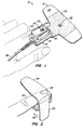
- Fig. 1 shows a sensor 10 according to the present invention.
- Sensor 10 consists of a flexible, disposable webbing 12 and a reusable housing 14.
- Housing 14 includes a rigid portion 16 and a deformable pad 18.
- Flexible web 12 includes a photoemitter 22, which preferably includes two photoemitters, one for red light and one for infrared light.
- a photodetector 24 is included in deformable pad 18.
- a copper grid 23 is disposed over photodetector 24.
- a transparent window 25 covers photodetector 24. All or substantially all of the portion of window 25 extending beyond photodetector 24 is colored black.
- a black area 29 is printed on the underside of foam layer 28.
- Grid 23, photodetector 24 and photoemitter 22 are electrically connected to a sensor monitoring system through conductors in a cable 26 connected to housing 14.
- Grid 23 is a Faraday shield (electrostatic screen) connected to ground for reducing interference.
- the thin window 25 extends over the copper grid so that the grid will not bulge out pad 18. Before the black coating was adding, shift errors in the data values were noticed. The black coating eliminated these errors. The reason is not certain, but the coating over the window may prevent reflections from most of the copper, while the black coating on the foam layer 28 may prevent light from being shunted through the foam layer to the detector, bypassing the finger.
- Webbing 12 has a top foam layer 28 with an adhesive surface. Before use, this adhesive layer is covered with protective plastic (not shown), which is peeled off for use.
- Fig. 2 illustrates how the flexible webbing 12 is bent over and attached to finger 20.
- a first arm 30 of the flexible web is wrapped around the side of housing 14 and will continue to be wrapped around its bottom in the direction of arrow 32.
- the other arm 34 will be wrapped around finger 20 and housing 14.
- photoemitters 22, shown in phantom are now on top of the finger, directly opposite photodetector 24, which is not visible in this view.
- only the bottom of finger 20 contacts deformable pad 18.
- At least the top of the finger will be adhered to by web 12.
- the sides and front may also be adhered to, depending on the shape of the finger and how the sensor is attached.
- the top is the portion which is most important to be adhering, since it contains the photoemitter which should not move relative to the finger. This provides a secure connection which reduces motion artifacts and puts the disposable, flexible portion in contact with most of the surfaces of the finger so that it is exposed to more contamination than the reusable portion.
- Fig. 3 illustrates the electrical connection between flexible web 12 and rigid housing 14.
- Fig. 3 shows adhesive layer 28 partially peeled back from a web base 36.
- an elongate plastic substrate 38 is placed, with a series of conductive traces 40 on its top surface. Two conductive traces connect to photoemitters 22, and two connect to a calibration resistor 55, described below.
- Elongate plastic substrate 38 forms a tail 42.
- Web base 36 can be just large enough to hold tail 42 to adhesive layer 28, as shown, or could conform to the shape of adhesive layer 28.
- Web base 36 has an adhesive surface for holding tail 42 to layer 28.
- a compressible foam member 44 is placed between the halves of tail 42.
- the foam is made of Poron foam from Roger's Corp.
- a pair of tabs 46 extend from the top half of the tail having the conductive traces. The tabs and the foam member provide part of the attachment mechanism as explained below.
- a channel 48 is formed on the bottom side of the rigid housing 16, opposite deformable pad 18.
- a series of electrical contacts 50 are located in the channel. The contacts are covered by a bridge 52 extending across the housing.
- a pair of grooves 54 are formed in the channel. The grooves are slightly larger than the tabs 46 on the flexible web.
- the tail 42 of the flexible circuit is inserted into the space beneath bridge 52.
- the plastic foam 44 compresses.
- the spring action of the foam pushes the tabs into the grooves.
- the tabs and grooves ensure that the flexible circuit is not inserted too far and prevent inadvertent removal of the flexible circuit.
- the spring action of the foam also pushes one set of contacts against the other to enhance the electrical connection.
- the scraping action of one set of contacts against the other during insertion and withdrawal of the flexible circuit will help remove any oxidation or debris on the contacts.
- the tabs are lifted out of the grooves by pulling the flexible web away from the housing and the tail is withdrawn from the space beneath the bridge.
- Cable 26 contains 6 wires. Two are connected to calibration resistor 55 through two of contacts 50 and conductive traces 40. Two are connected to photoemitters 22 through the other two of contacts 50 and conductive traces 40. The remaining two wires are connected to photodetector 24.
- the plastic substrate is formed from white, substantially opaque polyester.
- White nylon may also be used, or a clear plastic.
- the adhesive may be white, with a clear window for the photoemitters.
- the preferred embodiment of the sensor according to this invention includes an encoding/decoding system such as that described in U.S. Patent No. 4,621,643.
- the flexible web supports an encoding resistor 55 in electrical communication with the monitor.
- the value of the resistor is selected to match the wavelengths of the red and infrared LED's. That patent also describes the necessary sensor monitoring electronics.
- the sencoding resistor may be mounted in the flexible web with the emitters and the encoding resistor mounted in the rigid housing.
- the rigid housing is made from injection molded polycarbonate.
- injection molded ABS plastic may be used.
- Patent No. 4,685,464 contains additional details on construction of a rigid housing and deformable pad including the placement of the photodetector.
- the present invention may be embodied in other specific forms without departing from the spirit or essential characteristics thereof.
- the compression effect of foam 44 could be obtained instead by making bridge 52 a spring-action clip, which is opened by holding one end down during insertion and then released, with a spring on the clip holding the tab in place.
- the flexible portion could be attached to the finger and rigid housing using velcro or other securing mechanisms.
- the flexible web could be made of foil or other color materials than white or clear.
- the sensor could be a surface sensor, with adhesive for reducing motion artifact on the disposable portion. Accordingly, the disclosure of a preferred embodiment of the invention is intended to be illustrative, but not limiting, of the scope of the invention which is set forth in the following claims.
Abstract
Description
- This invention relates to sensors for use with non-invasive pulse monitors such as plethysmographs or pulse oximeters.
- A plethysmograph is a pulse monitor. The plethysmograph sensor shines light into the patient's tissue, and the light transmitted through the tissue is received by a photodetector. The photodetector generates electrical signals corresponding to the transmitted light levels and transmits the signals to a monitor for processing. Arterial blood will absorb some of the light, with more light being absorbed when there is more blood. Thus, changes in the amount of transmitted light are related to pulses of arterial blood in the illuminated tissue.
- A pulse oximeter is a device for noninvasively determining the oxygen saturation of arterial blood. The pulse oximeter sensor shines light at two different wavelengths (one in the red range, the other in the infrared range) through a portion of the patient's blood-perfused tissue. The red and infrared light transmitted through the tissue is detected by a photodetector. The amount of light absorbed varies with the amount of oxygen in the blood, and varies differently for red and infrared light. The pulse oximeter monitor computes blood oxygen saturation based on the changes in the two detected light levels between two points in time.
- There are several types of sensors for plethysmographs and pulse oximeters. One is a surface sensor in which the light emitter and the photodetector are mounted on the same sensor face. The sensor is attached to the patient with both the light emitter and the detector on the same side of the patient's appendage (e.g., on the patient's forehead). This type of sensor detects light reflected back from the tissue, rather than light transmitted through an appendage. The signal detected will thus be weaker in most cases. The sensor is typically attached with a strap, headband or tape over the sensor, or an adhesive pad between the sensor and the skin.
- Another type of sensor is a clamp design, such as that described in U.S. Patent No. 4,685,464. The durable sensor described in that patent has deformable pads creating conforming tissue contacting surfaces to which the emitters and photodetector are secured. The deformable pads are disposed in a hinged rigid housing that clips on the patient like a clothes pin. This relies on a clamping force to secure the sensor to the patient. The force of the sensor against the patient's tissue could reduce the flow of blood to that region. This exsanguination of the tissue beneath the sensor adversely affects pulse detection and analysis by suppressing the pulse in that portion of the tissue. As a result, the sensor site must typically be checked or moved every four hours to insure adequate perfusion. Because of its relatively large mass, however, the clamp design is more susceptible to signal-distorting motion artifact. i.e., differential motion between the sensor and the patient.
- A third sensor design is described in U.S. Patent No. 4,830,014. The conformable sensor described in that patent has emitters and a photodetector mounted in the same side of a flexible web. The web wraps around a portion of the patient's tissue (such as a finger) so that the light from the emitters must travel through the tissue before reaching the detector. The web attaches to the skin with an adhesive surface on the emitter and detector side of the web. Because of its relatively low mass and the adhesive, this sensor adheres closely to the patient's skin and minimizes the effects of motion artifact. In addition, its flexibility and use of adhesive to secure it minimizes the exsanguination caused by rigid sensors. Thus the sensor site typically only needs to be checked every eight hours. Conformable sensors, however, are typically restricted to one application due in part to a decrease in adhesive effectiveness with each application and in part to difficulties in cleaning and sterilization for reuse. Replacement of the sensor after only one use can make pulse oximetry expensive.
- The present invention provides a pulse oximeter sensor that is designed to surround an appendage of the patient, such as a finger, toe or foot. The sensor has a reusable member which preferably includes a photodetector. A disposable, flexible member preferably contains the photoemitter and can be wrapped around the patient's appendage to secure it to the appendage and the reusable member. When secured, the photoemitter and photodetector end up on opposite sides of the appendage. The disposable member connects to the reusable member to establish electrical contact. The reusable member is connected to a cable which can be plugged into a sensor monitoring system.
- In the preferred embodiment, the flexible member is a flexible adhesive web with arms extending laterally from a central portion. The reusable member is preferably a rigid housing with a deformable pad for contacting the appendage.
- To attach the sensor to the patient, the flexible web is adhesively attached to one side of the patient's appendage, and the rigid housing is placed on the other side directly opposite the flexible web. The arms extend around the appendage to adhesively hold the conformable pad of the rigid housing against the appendage. By reducing the mass of the sensor and by adhesively attaching the emitters to the skin, this configuration minimizes motion artifact by reducing the relative movement between the sensor and the patient's skin experienced by previous clamp-type sensors. In addition, the flexible web and conformable surface of the rigid housing minimize exsanguination of the tissue beneath the sensor. Since the sensor relies on adhesion to secure it to the patient, the sensor site should not need to be checked as often as for a clamping-type sensor.
- After use, the flexible web may be separated from the rigid housing, the rigid housing cleaned, and a new flexible web attached to the rigid housing. The fresh adhesive on the new flexible web provides a more reliable bond between the sensor and the patient than the adhesive on the previously-used web. In addition, since the flexible web covers four out of the five surfaces of the patient's appendage (including, when worn on the finger, the cuticle and subungual region), one time use of the flexible portion of the sensor minimizes cross-contamination between patients when the sensor is reused. Furthermore, because a portion of the sensor may be cleaned and reused, this new sensor design reduces the cost of using flexible sensors.
- The electrical connection between the flexible web and the rigid housing is preferably made with a tab extending from the flexible web having conductive traces printed on it which connect to the photoemitter. The conductive traces are inserted into a channel in the back of the housing which is covered by a bridge. Underneath the bridge are a series of electrical contacts for making connection with the conductive traces. The tab contains an internal resilient foam which is compressed as it is inserted between the housing and the bridge, and exerts an outward force to maintain the tab in place and create an electrical connection between the conductive traces and the contacts.
- For a fuller understanding of the nature and advantages of the invention, reference should be made to the ensuing detailed description taken in conjunction with the accompanying drawings.
-
- Fig. 1 is a perspective view of a sensor according to the present invention;
- Fig. 2 is a perspective view of the sensor of Fig. 1 showing the flexible web being wrapped around a finger; and
- Fig. 3 is a perspective view of the separated disposable and reusable members of Fig. 1 illustrating how the connection is made.
- Fig. 1 shows a sensor 10 according to the present invention. Sensor 10 consists of a flexible,
disposable webbing 12 and areusable housing 14.Housing 14 includes arigid portion 16 and adeformable pad 18. A patient's finger 20, shown in phantom, is shown placed on top ofdeformable pad 18. -
Flexible web 12 includes aphotoemitter 22, which preferably includes two photoemitters, one for red light and one for infrared light. Aphotodetector 24 is included indeformable pad 18. Acopper grid 23 is disposed overphotodetector 24. Atransparent window 25 coversphotodetector 24. All or substantially all of the portion ofwindow 25 extending beyondphotodetector 24 is colored black. In addition, ablack area 29 is printed on the underside offoam layer 28.Grid 23,photodetector 24 andphotoemitter 22 are electrically connected to a sensor monitoring system through conductors in acable 26 connected tohousing 14. -
Grid 23 is a Faraday shield (electrostatic screen) connected to ground for reducing interference. Thethin window 25 extends over the copper grid so that the grid will not bulge outpad 18. Before the black coating was adding, shift errors in the data values were noticed. The black coating eliminated these errors. The reason is not certain, but the coating over the window may prevent reflections from most of the copper, while the black coating on thefoam layer 28 may prevent light from being shunted through the foam layer to the detector, bypassing the finger. -
Webbing 12 has atop foam layer 28 with an adhesive surface. Before use, this adhesive layer is covered with protective plastic (not shown), which is peeled off for use. - Fig. 2 illustrates how the
flexible webbing 12 is bent over and attached to finger 20. Afirst arm 30 of the flexible web is wrapped around the side ofhousing 14 and will continue to be wrapped around its bottom in the direction ofarrow 32. Similarly, theother arm 34 will be wrapped around finger 20 andhousing 14. As can be seen,photoemitters 22, shown in phantom, are now on top of the finger, directly oppositephotodetector 24, which is not visible in this view. As can be seen, only the bottom of finger 20 contacts deformablepad 18. At least the top of the finger will be adhered to byweb 12. The sides and front may also be adhered to, depending on the shape of the finger and how the sensor is attached. The top is the portion which is most important to be adhering, since it contains the photoemitter which should not move relative to the finger. This provides a secure connection which reduces motion artifacts and puts the disposable, flexible portion in contact with most of the surfaces of the finger so that it is exposed to more contamination than the reusable portion. - Fig. 3 illustrates the electrical connection between
flexible web 12 andrigid housing 14. Fig. 3 showsadhesive layer 28 partially peeled back from aweb base 36. In betweenweb base 36 andadhesive layer 28, an elongateplastic substrate 38 is placed, with a series ofconductive traces 40 on its top surface. Two conductive traces connect to photoemitters 22, and two connect to acalibration resistor 55, described below. Elongateplastic substrate 38 forms atail 42.Web base 36 can be just large enough to holdtail 42 toadhesive layer 28, as shown, or could conform to the shape ofadhesive layer 28.Web base 36 has an adhesive surface for holdingtail 42 tolayer 28. - A
compressible foam member 44 is placed between the halves oftail 42. In the preferred embodiment, the foam is made of Poron foam from Roger's Corp. A pair oftabs 46 extend from the top half of the tail having the conductive traces. The tabs and the foam member provide part of the attachment mechanism as explained below. - A
channel 48 is formed on the bottom side of therigid housing 16, oppositedeformable pad 18. A series of electrical contacts 50 (shown in phantom) are located in the channel. The contacts are covered by abridge 52 extending across the housing. A pair ofgrooves 54 are formed in the channel. The grooves are slightly larger than thetabs 46 on the flexible web. - To connect the flexible web to the rigid housing, the
tail 42 of the flexible circuit is inserted into the space beneathbridge 52. As the tail moves forward, theplastic foam 44 compresses. As the tail'stabs 46 move over the channel'sgrooves 54, the spring action of the foam pushes the tabs into the grooves. The tabs and grooves ensure that the flexible circuit is not inserted too far and prevent inadvertent removal of the flexible circuit. The spring action of the foam also pushes one set of contacts against the other to enhance the electrical connection. In addition, the scraping action of one set of contacts against the other during insertion and withdrawal of the flexible circuit will help remove any oxidation or debris on the contacts. To remove, the tabs are lifted out of the grooves by pulling the flexible web away from the housing and the tail is withdrawn from the space beneath the bridge. -
Cable 26 contains 6 wires. Two are connected tocalibration resistor 55 through two ofcontacts 50 and conductive traces 40. Two are connected to photoemitters 22 through the other two ofcontacts 50 and conductive traces 40. The remaining two wires are connected tophotodetector 24. - In the preferred embodiment, the plastic substrate is formed from white, substantially opaque polyester. White nylon may also be used, or a clear plastic. The adhesive may be white, with a clear window for the photoemitters.
- The preferred embodiment of the sensor according to this invention includes an encoding/decoding system such as that described in U.S. Patent No. 4,621,643. The flexible web supports an
encoding resistor 55 in electrical communication with the monitor. As explained in that patent, the value of the resistor is selected to match the wavelengths of the red and infrared LED's. That patent also describes the necessary sensor monitoring electronics. - In an alternative embodiment, the sensor's photodetector may be mounted in the flexible web with the emitters and the encoding resistor mounted in the rigid housing.
- In the preferred embodiment, the rigid housing is made from injection molded polycarbonate. Alternatively, injection molded ABS plastic may be used. Patent No. 4,685,464 contains additional details on construction of a rigid housing and deformable pad including the placement of the photodetector.
- As will be understood by those familiar with the art, the present invention may be embodied in other specific forms without departing from the spirit or essential characteristics thereof. For example, the compression effect of
foam 44 could be obtained instead by making bridge 52 a spring-action clip, which is opened by holding one end down during insertion and then released, with a spring on the clip holding the tab in place. Other variations in the way electrical contact is made are also possible. Instead of the adhesive layer, the flexible portion could be attached to the finger and rigid housing using velcro or other securing mechanisms. The flexible web could be made of foil or other color materials than white or clear. The sensor could be a surface sensor, with adhesive for reducing motion artifact on the disposable portion. Accordingly, the disclosure of a preferred embodiment of the invention is intended to be illustrative, but not limiting, of the scope of the invention which is set forth in the following claims.
Claims (17)
- A sensor (10) for attaching to a patient (20) for electrooptical measurement of blood characteristics, comprising: a reusable member (14) including a first electronic device (24) for emitting or detecting electromagnetic radiation; conducting means (26), connected to said reusable member (14), for electrically connecting the first electronic device (24) to an external sensor monitoring system; a disposable, flexible member (12) including a second electronic device (22) for detecting electromagnetic radiation emitted by the first electronic device (24) or emitting electromagnetic radiation to be detected by the first electronic device (24); means (38) for removably coupling the flexible member (12) to the reusable member (14) to provide a connection between the second electronic device (22) and the conducting means (26); and means (28) for securing the disposable, flexible member and the reusable member to said patient.
- A sensor according to claim 1, wherein the means (28) for securing comprises an adhesive on said disposable, flexible member.
- A sensor according to claim 1 or 2, wherein the second electronic device (22) is a photoemitter.
- A sensor according to claim 1, 2 or 3, wherein the means (38) for removably coupling comprises a tail (42) extending from the disposable, flexible member (12) having at least one exposed first electrical conductor (40), at least one exposed second electrical conductor (50) extending from the reusable member (14), and a bridge (52) connected to the reusable member (14) and extending across the second electrical conductor (50) to allow the tail (42) to be inserted between the bridge (52) and the second conductor (50).
- A sensor according to claim 4, wherein the tail (42) includes resilient means (44) for applying force between the second conductor (50) and the bridge (52) to hold the tail (42) in place.
- A sensor according to any preceding claim, wherein the reusable member (14) comprises a rigid housing (16) and deformable means (18), attached to the housing, for securely gripping and complying to the patient (20).
- A sensor according to any preceding claim, wherein the second electronic device (22) comprises a red light photoemitter and an infrared photoemitter.
- A sensor according to claim 7, wherein the first electronic device (24) is a photodetector.
- A sensor according to any preceding claim, wherein the means (28) for securing attaches the sensor (10) to an appendage (20) of the patient so that the first electronic device (24) is on an opposite side of the appendage (20) from the second electronic device (22).
- A sensor according to any preceding claim, further comprising a black coating on the flexible member (12) around the second electronic device (22).
- A sensor according to any preceding claim, further comprising: an electrostatic screen (23) adjacent the first electronic device (24); and a thin film (25) covering the first electronic device (24) and at least a portion of the electrostatic screen (23) the film (25) being transparent over the first electronic device (24) and opaque over the portion of the electrostatic screen (23).
- A sensor (10) according to claim 1 for attaching to an appendage (20) of a patient for electrooptical measurement of blood characteristics, comprising: a reusable member (14) including a first electronic device (24) for emitting or detecting light; conducting means (26) for electrically connecting the first electronic device (24) to an external sensor monitoring system; a disposable, flexible member (12) including a second electronic device (22) for detecting light emitted by the first electronic device (24) or emitting light to be detected by the first electronic device (24); a tail (42) extending from the disposable, flexible member (12) having at least one exposed first electrical conductor (40), at least one exposed second electrical conductor (50) extending from the reusable member (14), and a bridge (52) connected to the reusable member (14) and extending across the second electrical conductor (50) to allow the tail (42) to be inserted between the bridge (52) and the second conductor (50); means (28) for securing the disposable, flexible member (12) to the appendage (20) and the reusable member (14) so that the first electronic device (24) is on an opposite side of the appendage (20) from the second electronic device (22).
- A sensor according to claim 12, wherein the means (28) for securing comprises an adhesive on the disposable, flexible member (12).
- A sensor according to claim 12 or 13, wherein the second electronic device (22) is a photoemitter.
- A sensor according to claim 12, wherein the tail (42) includes resilient means (44) for applying force between the second conductor (50) and the bridge (52) to hold the tail (42) in place.
- A sensor according to claim 1 wherein the sensor is arranged to be attached to an appendage of a patient for electrooptical measurement of blood characteristics, the first electronic device (24) comprising a photodetector; the second electronic device (22) comprising at least one photoemitter for emitting light to be detected by the photodetector and the means (28) for securing comprising an adhesive coating on the disposable, flexible member for securing the disposable, flexible member (12) to the appendage (20) and the reusable member (14) so that the photodetector is on an opposite side of the appendage (20) from the or each photoemitter.
- A sensor according to claim 1 wherein the sensor is arranged to be attached to an appendage of a patient for electrooptical measurement of blood characteristics, the first electronic device (24) comprising at least one photodetector, the reusable member (14) including a rigid housing (16) and a deformable means (18), attached to the housing (16), for securely gripping and complying to the patient's appendage (20); the second electronic device (22) comprising a red light photoemitter and an infrared photoemitter for emitting light to be detected by the photodetector; the sensor (10) further comprising a tail (42) extending from the disposable, flexible member (12) having at least one exposed first electrical conductor (40); at least one exposed second electrical conductor (50) extending from the rigid housing (16); a bridge (52) connected to the rigid housing (16) and extending across the second electrical conductor (50) to allow the tail (42) to be inserted between the bridge (52) and said second conductor (50); resilient means (44), coupled to the tail (42), for applying force between the second conductor (50) and the bridge (52) to hold the tail (42) in place; and an adhesive coating (28) on the disposable, flexible member (12) for securing the disposable, flexible member (12) to the appendage (20) and the reusable member (14) so that the photoemitter is on an opposite side of the appendage (20) from the photodetector.
Applications Claiming Priority (4)
| Application Number | Priority Date | Filing Date | Title |
|---|---|---|---|
| US60054190A | 1990-10-19 | 1990-10-19 | |
| US600541 | 1990-10-19 | ||
| US741290 | 1991-08-06 | ||
| US07/741,290 US5209230A (en) | 1990-10-19 | 1991-08-06 | Adhesive pulse oximeter sensor with reusable portion |
Publications (2)
| Publication Number | Publication Date |
|---|---|
| EP0481612A1 EP0481612A1 (en) | 1992-04-22 |
| EP0481612B1 true EP0481612B1 (en) | 1996-03-13 |
Family
ID=27083629
Family Applications (1)
| Application Number | Title | Priority Date | Filing Date |
|---|---|---|---|
| EP91308738A Expired - Lifetime EP0481612B1 (en) | 1990-10-19 | 1991-09-25 | Adhesive pulse oximeter sensor with reusable portion |
Country Status (8)
| Country | Link |
|---|---|
| US (2) | US5209230A (en) |
| EP (1) | EP0481612B1 (en) |
| JP (1) | JPH04269945A (en) |
| AT (1) | ATE135178T1 (en) |
| AU (1) | AU644226B2 (en) |
| CA (1) | CA2052650A1 (en) |
| DE (1) | DE69117861T2 (en) |
| FI (1) | FI914861A (en) |
Cited By (2)
| Publication number | Priority date | Publication date | Assignee | Title |
|---|---|---|---|---|
| US6541756B2 (en) | 1991-03-21 | 2003-04-01 | Masimo Corporation | Shielded optical probe having an electrical connector |
| US9560998B2 (en) | 2006-10-12 | 2017-02-07 | Masimo Corporation | System and method for monitoring the life of a physiological sensor |
Families Citing this family (201)
| Publication number | Priority date | Publication date | Assignee | Title |
|---|---|---|---|---|
| US5438201A (en) * | 1990-06-27 | 1995-08-01 | Futrex, Inc. | Method and apparatus for restraining finger motion in blood analyte optical measurement |
| US5209230A (en) * | 1990-10-19 | 1993-05-11 | Nellcor Incorporated | Adhesive pulse oximeter sensor with reusable portion |
| US5645440A (en) * | 1995-10-16 | 1997-07-08 | Masimo Corporation | Patient cable connector |
| US6580086B1 (en) | 1999-08-26 | 2003-06-17 | Masimo Corporation | Shielded optical probe and method |
| US5638818A (en) | 1991-03-21 | 1997-06-17 | Masimo Corporation | Low noise optical probe |
| US5368025A (en) * | 1991-08-22 | 1994-11-29 | Sensor Devices, Inc. | Non-invasive oximeter probe |
| US5246003A (en) * | 1991-08-28 | 1993-09-21 | Nellcor Incorporated | Disposable pulse oximeter sensor |
| US5249576A (en) * | 1991-10-24 | 1993-10-05 | Boc Health Care, Inc. | Universal pulse oximeter probe |
| US5263244A (en) * | 1992-04-17 | 1993-11-23 | Gould Inc. | Method of making a flexible printed circuit sensor assembly for detecting optical pulses |
| DE69211986T2 (en) * | 1992-05-15 | 1996-10-31 | Hewlett Packard Gmbh | Medical sensor |
| US5339810A (en) * | 1993-05-03 | 1994-08-23 | Marquette Electronics, Inc. | Pulse oximetry sensor |
| JPH09501074A (en) * | 1993-05-20 | 1997-02-04 | ソマネテイツクス コーポレイシヨン | Improved electro-optical sensor for spectrophotometric medical devices |
| US5475420A (en) * | 1993-06-09 | 1995-12-12 | Origin Medsystems, Inc. | Video imaging system with image processing optimized for small-diameter endoscopes |
| US5438986A (en) * | 1993-12-14 | 1995-08-08 | Criticare Systems, Inc. | Optical sensor |
| US5490523A (en) * | 1994-06-29 | 1996-02-13 | Nonin Medical Inc. | Finger clip pulse oximeter |
| DE4429845C1 (en) * | 1994-08-23 | 1995-10-19 | Hewlett Packard Gmbh | Pulse oximeter with flexible strap for attachment to hand or foot |
| US5697367A (en) * | 1994-10-14 | 1997-12-16 | Somanetics Corporation | Specially grounded sensor for clinical spectrophotometric procedures |
| US5758644A (en) | 1995-06-07 | 1998-06-02 | Masimo Corporation | Manual and automatic probe calibration |
| EP0901338A1 (en) * | 1995-07-03 | 1999-03-17 | Sensor Devices, Inc. | Apparatus for determining spectral absorption |
| US6095974A (en) * | 1995-07-21 | 2000-08-01 | Respironics, Inc. | Disposable fiber optic probe |
| DE69635228T2 (en) * | 1995-07-21 | 2006-05-18 | Respironics, Inc. | DEVICE FOR PULSE OXIMETRY THROUGH LASER DIODE BY MULTIFASER OPTICAL CABLES AND DISPOSABLE FIBER OPTIC PROBE |
| DE19541605C2 (en) * | 1995-11-08 | 1999-06-24 | Hewlett Packard Co | Sensor and method for performing medical measurements, in particular pulse oximetric measurements, on the human finger |
| US5810724A (en) * | 1995-12-01 | 1998-09-22 | Nellcor Puritan Bennett Incorporated | Reusable sensor accessory containing a conformable spring activated rubber sleeved clip |
| US5891026A (en) * | 1996-01-29 | 1999-04-06 | Ntc Technology Inc. | Extended life disposable pulse oximetry sensor and method of making |
| US5797841A (en) * | 1996-03-05 | 1998-08-25 | Nellcor Puritan Bennett Incorporated | Shunt barrier in pulse oximeter sensor |
| US7190984B1 (en) * | 1996-03-05 | 2007-03-13 | Nellcor Puritan Bennett Incorporated | Shunt barrier in pulse oximeter sensor |
| US6253097B1 (en) * | 1996-03-06 | 2001-06-26 | Datex-Ohmeda, Inc. | Noninvasive medical monitoring instrument using surface emitting laser devices |
| US6018673A (en) | 1996-10-10 | 2000-01-25 | Nellcor Puritan Bennett Incorporated | Motion compatible sensor for non-invasive optical blood analysis |
| US5817010A (en) * | 1997-03-25 | 1998-10-06 | Ohmeda Inc. | Disposable sensor holder |
| US6002952A (en) | 1997-04-14 | 1999-12-14 | Masimo Corporation | Signal processing apparatus and method |
| US5924873A (en) * | 1997-05-15 | 1999-07-20 | Chrysler Corporation | Flexible circuit board interconnect with strain relief |
| WO1999000053A1 (en) * | 1997-06-27 | 1999-01-07 | Toa Medical Electronics Co., Ltd. | Living body inspecting apparatus and noninvasive blood analyzer using the same |
| US6099481A (en) | 1997-11-03 | 2000-08-08 | Ntc Technology, Inc. | Respiratory profile parameter determination method and apparatus |
| US6184521B1 (en) * | 1998-01-06 | 2001-02-06 | Masimo Corporation | Photodiode detector with integrated noise shielding |
| US6179159B1 (en) | 1998-01-26 | 2001-01-30 | Mariruth D. Gurley | Communicable disease barrier digit cover and dispensing package therefor |
| IL124787A0 (en) * | 1998-06-07 | 1999-01-26 | Itamar Medical C M 1997 Ltd | Pressure applicator devices particularly useful for non-invasive detection of medical conditions |
| US5999834A (en) * | 1998-06-18 | 1999-12-07 | Ntc Technology, Inc. | Disposable adhesive wrap for use with reusable pulse oximetry sensor and method of making |
| US6519487B1 (en) | 1998-10-15 | 2003-02-11 | Sensidyne, Inc. | Reusable pulse oximeter probe and disposable bandage apparatus |
| US6684091B2 (en) | 1998-10-15 | 2004-01-27 | Sensidyne, Inc. | Reusable pulse oximeter probe and disposable bandage method |
| US6721585B1 (en) | 1998-10-15 | 2004-04-13 | Sensidyne, Inc. | Universal modular pulse oximeter probe for use with reusable and disposable patient attachment devices |
| USRE41912E1 (en) | 1998-10-15 | 2010-11-02 | Masimo Corporation | Reusable pulse oximeter probe and disposable bandage apparatus |
| US6321100B1 (en) | 1999-07-13 | 2001-11-20 | Sensidyne, Inc. | Reusable pulse oximeter probe with disposable liner |
| US7245953B1 (en) | 1999-04-12 | 2007-07-17 | Masimo Corporation | Reusable pulse oximeter probe and disposable bandage apparatii |
| US6343224B1 (en) | 1998-10-15 | 2002-01-29 | Sensidyne, Inc. | Reusable pulse oximeter probe and disposable bandage apparatus |
| US6061584A (en) * | 1998-10-28 | 2000-05-09 | Lovejoy; David A. | Pulse oximetry sensor |
| US7047054B2 (en) * | 1999-03-12 | 2006-05-16 | Cas Medical Systems, Inc. | Laser diode optical transducer assembly for non-invasive spectrophotometric blood oxygenation monitoring |
| US6675031B1 (en) | 1999-04-14 | 2004-01-06 | Mallinckrodt Inc. | Method and circuit for indicating quality and accuracy of physiological measurements |
| US6515273B2 (en) | 1999-08-26 | 2003-02-04 | Masimo Corporation | System for indicating the expiration of the useful operating life of a pulse oximetry sensor |
| ATE287237T1 (en) | 1999-11-22 | 2005-02-15 | Mallinckrodt Inc | PULSE OXIMETER SENSOR WITH A WIDER METAL STRAP |
| JP2001149349A (en) * | 1999-11-26 | 2001-06-05 | Nippon Koden Corp | Sensor for living body |
| US6542764B1 (en) | 1999-12-01 | 2003-04-01 | Masimo Corporation | Pulse oximeter monitor for expressing the urgency of the patient's condition |
| US6671531B2 (en) | 1999-12-09 | 2003-12-30 | Masimo Corporation | Sensor wrap including foldable applicator |
| US6377829B1 (en) * | 1999-12-09 | 2002-04-23 | Masimo Corporation | Resposable pulse oximetry sensor |
| US6950687B2 (en) | 1999-12-09 | 2005-09-27 | Masimo Corporation | Isolation and communication element for a resposable pulse oximetry sensor |
| US6385821B1 (en) | 2000-02-17 | 2002-05-14 | Udt Sensors, Inc. | Apparatus for securing an oximeter probe to a patient |
| EP2322085B1 (en) | 2000-04-17 | 2014-03-12 | Covidien LP | Pulse oximeter sensor with piece-wise function |
| US8224412B2 (en) | 2000-04-17 | 2012-07-17 | Nellcor Puritan Bennett Llc | Pulse oximeter sensor with piece-wise function |
| US6490466B1 (en) | 2000-09-21 | 2002-12-03 | Mallinckrodt Inc. | Interconnect circuit between non-compatible oximeter and sensor |
| US6571113B1 (en) | 2000-09-21 | 2003-05-27 | Mallinckrodt, Inc. | Oximeter sensor adapter with coding element |
| US6654621B2 (en) * | 2001-08-29 | 2003-11-25 | Bci, Inc. | Finger oximeter with finger grip suspension system |
| US6671532B1 (en) * | 2001-09-17 | 2003-12-30 | Respironics Novametrix, Inc. | Pulse oximetry sensor and dispensing method |
| US6748254B2 (en) | 2001-10-12 | 2004-06-08 | Nellcor Puritan Bennett Incorporated | Stacked adhesive optical sensor |
| US6850788B2 (en) | 2002-03-25 | 2005-02-01 | Masimo Corporation | Physiological measurement communications adapter |
| KR20040017378A (en) * | 2002-08-21 | 2004-02-27 | 주식회사 바이오프로테크 | A sensor unit of a instrument for measuring oxygen-saturation |
| US6745061B1 (en) | 2002-08-21 | 2004-06-01 | Datex-Ohmeda, Inc. | Disposable oximetry sensor |
| US7698909B2 (en) | 2002-10-01 | 2010-04-20 | Nellcor Puritan Bennett Llc | Headband with tension indicator |
| EP1549165B8 (en) | 2002-10-01 | 2010-10-06 | Nellcor Puritan Bennett LLC | Use of a headband to indicate tension and system comprising an oximetry sensor and a headband |
| US7190986B1 (en) | 2002-10-18 | 2007-03-13 | Nellcor Puritan Bennett Inc. | Non-adhesive oximeter sensor for sensitive skin |
| WO2004041330A2 (en) | 2002-11-05 | 2004-05-21 | M 2 Medical A/S | A disposable wearable insulin dispensing device, a combination of such a device and a programming controller and a method of controlling the operation of such a device |
| US6920345B2 (en) * | 2003-01-24 | 2005-07-19 | Masimo Corporation | Optical sensor including disposable and reusable elements |
| US7047056B2 (en) | 2003-06-25 | 2006-05-16 | Nellcor Puritan Bennett Incorporated | Hat-based oximeter sensor |
| US7500950B2 (en) | 2003-07-25 | 2009-03-10 | Masimo Corporation | Multipurpose sensor port |
| US8412297B2 (en) | 2003-10-01 | 2013-04-02 | Covidien Lp | Forehead sensor placement |
| US20050075550A1 (en) * | 2003-10-03 | 2005-04-07 | Lindekugel Eric W. | Quick-clip sensor holder |
| GB2413078C (en) | 2004-01-08 | 2012-08-15 | Dialog Devices Ltd | A system or method for assessing a subject's pedalblood circulation. |
| US7440788B2 (en) * | 2004-08-26 | 2008-10-21 | Kelvyn Enterprises, Inc. | Oral health measurement clamping probe, system, and method |
| US20070121113A1 (en) * | 2004-12-22 | 2007-05-31 | Cohen David S | Transmission-based optical detection systems |
| US7706853B2 (en) * | 2005-02-10 | 2010-04-27 | Terumo Cardiovascular Systems Corporation | Near infrared spectroscopy device with reusable portion |
| US7761127B2 (en) | 2005-03-01 | 2010-07-20 | Masimo Laboratories, Inc. | Multiple wavelength sensor substrate |
| US20060224056A1 (en) * | 2005-03-30 | 2006-10-05 | Kermani Mahyar Z | Method for monitoring an implanted fluorescent light-emitting bead |
| US20060229507A1 (en) * | 2005-03-30 | 2006-10-12 | Kermani Mahyar Z | Adhesive fluorescence measurement band |
| US20060229508A1 (en) * | 2005-03-30 | 2006-10-12 | Kermani Mahyar Z | Adhesive fluorescence measurement patch |
| US20060224055A1 (en) * | 2005-03-30 | 2006-10-05 | Kermani Mahyar Z | Fluorescence measurement analytical kit |
| WO2006105793A1 (en) | 2005-04-06 | 2006-10-12 | M 2 Medical A/S | Method and device for dispensing liquid medicine by means of a twistable element |
| JP4721130B2 (en) * | 2005-07-29 | 2011-07-13 | 日本光電工業株式会社 | Pulse oximeter probe |
| US7657294B2 (en) | 2005-08-08 | 2010-02-02 | Nellcor Puritan Bennett Llc | Compliant diaphragm medical sensor and technique for using the same |
| US7657295B2 (en) | 2005-08-08 | 2010-02-02 | Nellcor Puritan Bennett Llc | Medical sensor and technique for using the same |
| US7590439B2 (en) | 2005-08-08 | 2009-09-15 | Nellcor Puritan Bennett Llc | Bi-stable medical sensor and technique for using the same |
| US20070060808A1 (en) | 2005-09-12 | 2007-03-15 | Carine Hoarau | Medical sensor for reducing motion artifacts and technique for using the same |
| DK1933901T3 (en) | 2005-09-26 | 2015-04-07 | Asante Solutions Inc | PORTABLE infusion pump FLEXIBLE SHOCK TOOL WITH HINGED PARTS |
| US7534226B2 (en) | 2005-09-26 | 2009-05-19 | M2 Group Holdings, Inc. | Dispensing fluid from an infusion pump system |
| US8551046B2 (en) | 2006-09-18 | 2013-10-08 | Asante Solutions, Inc. | Dispensing fluid from an infusion pump system |
| US8092379B2 (en) | 2005-09-29 | 2012-01-10 | Nellcor Puritan Bennett Llc | Method and system for determining when to reposition a physiological sensor |
| US7904130B2 (en) | 2005-09-29 | 2011-03-08 | Nellcor Puritan Bennett Llc | Medical sensor and technique for using the same |
| US7899510B2 (en) | 2005-09-29 | 2011-03-01 | Nellcor Puritan Bennett Llc | Medical sensor and technique for using the same |
| US7869850B2 (en) | 2005-09-29 | 2011-01-11 | Nellcor Puritan Bennett Llc | Medical sensor for reducing motion artifacts and technique for using the same |
| US7881762B2 (en) | 2005-09-30 | 2011-02-01 | Nellcor Puritan Bennett Llc | Clip-style medical sensor and technique for using the same |
| US8062221B2 (en) | 2005-09-30 | 2011-11-22 | Nellcor Puritan Bennett Llc | Sensor for tissue gas detection and technique for using the same |
| US7555327B2 (en) | 2005-09-30 | 2009-06-30 | Nellcor Puritan Bennett Llc | Folding medical sensor and technique for using the same |
| US7486979B2 (en) | 2005-09-30 | 2009-02-03 | Nellcor Puritan Bennett Llc | Optically aligned pulse oximetry sensor and technique for using the same |
| US7483731B2 (en) | 2005-09-30 | 2009-01-27 | Nellcor Puritan Bennett Llc | Medical sensor and technique for using the same |
| US8233954B2 (en) | 2005-09-30 | 2012-07-31 | Nellcor Puritan Bennett Llc | Mucosal sensor for the assessment of tissue and blood constituents and technique for using the same |
| DK1951340T4 (en) * | 2005-11-08 | 2017-05-22 | Bigfoot Biomedical Inc | infusion pump |
| WO2007064984A2 (en) | 2005-11-29 | 2007-06-07 | Masimo Corporation | Optical sensor including disposable and reusable elements |
| US7990382B2 (en) | 2006-01-03 | 2011-08-02 | Masimo Corporation | Virtual display |
| US8073518B2 (en) | 2006-05-02 | 2011-12-06 | Nellcor Puritan Bennett Llc | Clip-style medical sensor and technique for using the same |
| US10188348B2 (en) | 2006-06-05 | 2019-01-29 | Masimo Corporation | Parameter upgrade system |
| US8145288B2 (en) | 2006-08-22 | 2012-03-27 | Nellcor Puritan Bennett Llc | Medical sensor for reducing signal artifacts and technique for using the same |
| US8219170B2 (en) | 2006-09-20 | 2012-07-10 | Nellcor Puritan Bennett Llc | System and method for practicing spectrophotometry using light emitting nanostructure devices |
| US8396527B2 (en) | 2006-09-22 | 2013-03-12 | Covidien Lp | Medical sensor for reducing signal artifacts and technique for using the same |
| US8195264B2 (en) * | 2006-09-22 | 2012-06-05 | Nellcor Puritan Bennett Llc | Medical sensor for reducing signal artifacts and technique for using the same |
| US8175671B2 (en) | 2006-09-22 | 2012-05-08 | Nellcor Puritan Bennett Llc | Medical sensor for reducing signal artifacts and technique for using the same |
| US7869849B2 (en) | 2006-09-26 | 2011-01-11 | Nellcor Puritan Bennett Llc | Opaque, electrically nonconductive region on a medical sensor |
| US7574245B2 (en) | 2006-09-27 | 2009-08-11 | Nellcor Puritan Bennett Llc | Flexible medical sensor enclosure |
| US7890153B2 (en) | 2006-09-28 | 2011-02-15 | Nellcor Puritan Bennett Llc | System and method for mitigating interference in pulse oximetry |
| US7796403B2 (en) | 2006-09-28 | 2010-09-14 | Nellcor Puritan Bennett Llc | Means for mechanical registration and mechanical-electrical coupling of a faraday shield to a photodetector and an electrical circuit |
| US7476131B2 (en) | 2006-09-29 | 2009-01-13 | Nellcor Puritan Bennett Llc | Device for reducing crosstalk |
| US7684842B2 (en) | 2006-09-29 | 2010-03-23 | Nellcor Puritan Bennett Llc | System and method for preventing sensor misuse |
| US7680522B2 (en) | 2006-09-29 | 2010-03-16 | Nellcor Puritan Bennett Llc | Method and apparatus for detecting misapplied sensors |
| US8068891B2 (en) | 2006-09-29 | 2011-11-29 | Nellcor Puritan Bennett Llc | Symmetric LED array for pulse oximetry |
| US8175667B2 (en) | 2006-09-29 | 2012-05-08 | Nellcor Puritan Bennett Llc | Symmetric LED array for pulse oximetry |
| US8255026B1 (en) | 2006-10-12 | 2012-08-28 | Masimo Corporation, Inc. | Patient monitor capable of monitoring the quality of attached probes and accessories |
| US20080297764A1 (en) * | 2006-11-13 | 2008-12-04 | Weinmann Gerate Fur Medizin Gmbh + Co. Kg | Sensor for determining body parameters |
| US8600467B2 (en) | 2006-11-29 | 2013-12-03 | Cercacor Laboratories, Inc. | Optical sensor including disposable and reusable elements |
| US8326392B2 (en) * | 2007-02-27 | 2012-12-04 | Nonin Medical, Inc. | Foldable sensor device and method of using same |
| US8265724B2 (en) | 2007-03-09 | 2012-09-11 | Nellcor Puritan Bennett Llc | Cancellation of light shunting |
| US8280469B2 (en) | 2007-03-09 | 2012-10-02 | Nellcor Puritan Bennett Llc | Method for detection of aberrant tissue spectra |
| US7894869B2 (en) | 2007-03-09 | 2011-02-22 | Nellcor Puritan Bennett Llc | Multiple configuration medical sensor and technique for using the same |
| EP2139383B1 (en) | 2007-03-27 | 2013-02-13 | Masimo Laboratories, Inc. | Multiple wavelength optical sensor |
| US8374665B2 (en) | 2007-04-21 | 2013-02-12 | Cercacor Laboratories, Inc. | Tissue profile wellness monitor |
| US7703334B2 (en) * | 2007-10-04 | 2010-04-27 | Medility Llc | Bandage type sensor arrangement and carrier assembly therefore, and method of manufacture |
| US8352004B2 (en) | 2007-12-21 | 2013-01-08 | Covidien Lp | Medical sensor and technique for using the same |
| US8346328B2 (en) | 2007-12-21 | 2013-01-01 | Covidien Lp | Medical sensor and technique for using the same |
| US8366613B2 (en) | 2007-12-26 | 2013-02-05 | Covidien Lp | LED drive circuit for pulse oximetry and method for using same |
| US8577434B2 (en) | 2007-12-27 | 2013-11-05 | Covidien Lp | Coaxial LED light sources |
| US20090171176A1 (en) * | 2007-12-28 | 2009-07-02 | Nellcor Puritan Bennett Llc | Snapshot Sensor |
| US8452364B2 (en) | 2007-12-28 | 2013-05-28 | Covidien LLP | System and method for attaching a sensor to a patient's skin |
| US8442608B2 (en) | 2007-12-28 | 2013-05-14 | Covidien Lp | System and method for estimating physiological parameters by deconvolving artifacts |
| US8199007B2 (en) | 2007-12-31 | 2012-06-12 | Nellcor Puritan Bennett Llc | Flex circuit snap track for a biometric sensor |
| US8092993B2 (en) | 2007-12-31 | 2012-01-10 | Nellcor Puritan Bennett Llc | Hydrogel thin film for use as a biosensor |
| US8070508B2 (en) | 2007-12-31 | 2011-12-06 | Nellcor Puritan Bennett Llc | Method and apparatus for aligning and securing a cable strain relief |
| US8897850B2 (en) | 2007-12-31 | 2014-11-25 | Covidien Lp | Sensor with integrated living hinge and spring |
| US8437822B2 (en) | 2008-03-28 | 2013-05-07 | Covidien Lp | System and method for estimating blood analyte concentration |
| US8112375B2 (en) | 2008-03-31 | 2012-02-07 | Nellcor Puritan Bennett Llc | Wavelength selection and outlier detection in reduced rank linear models |
| US7956603B2 (en) * | 2008-06-16 | 2011-06-07 | Medility Llc | Sensor inductors, sensors for monitoring movements and positioning, apparatus, systems and methods therefore |
| US20090309578A1 (en) * | 2008-06-16 | 2009-12-17 | Cochran William T | Sensor inductors, sensors for monitoring movements and positioning, apparatus, systems and methods therefore |
| US20090309683A1 (en) * | 2008-06-16 | 2009-12-17 | Cochran William T | Sensor inductors, sensors for monitoring movements and positioning, apparatus, systems and methods therefore |
| US7880884B2 (en) | 2008-06-30 | 2011-02-01 | Nellcor Puritan Bennett Llc | System and method for coating and shielding electronic sensor components |
| US20090326347A1 (en) * | 2008-06-30 | 2009-12-31 | Bennett Scharf | Synchronous Light Detection Utilizing CMOS/CCD Sensors For Oximetry Sensing |
| US8071935B2 (en) | 2008-06-30 | 2011-12-06 | Nellcor Puritan Bennett Llc | Optical detector with an overmolded faraday shield |
| US7887345B2 (en) * | 2008-06-30 | 2011-02-15 | Nellcor Puritan Bennett Llc | Single use connector for pulse oximetry sensors |
| US20100004518A1 (en) | 2008-07-03 | 2010-01-07 | Masimo Laboratories, Inc. | Heat sink for noninvasive medical sensor |
| US8630691B2 (en) | 2008-08-04 | 2014-01-14 | Cercacor Laboratories, Inc. | Multi-stream sensor front ends for noninvasive measurement of blood constituents |
| US7959598B2 (en) | 2008-08-20 | 2011-06-14 | Asante Solutions, Inc. | Infusion pump systems and methods |
| US8364220B2 (en) | 2008-09-25 | 2013-01-29 | Covidien Lp | Medical sensor and technique for using the same |
| US8257274B2 (en) | 2008-09-25 | 2012-09-04 | Nellcor Puritan Bennett Llc | Medical sensor and technique for using the same |
| US8914088B2 (en) | 2008-09-30 | 2014-12-16 | Covidien Lp | Medical sensor and technique for using the same |
| US8417309B2 (en) | 2008-09-30 | 2013-04-09 | Covidien Lp | Medical sensor |
| US8423112B2 (en) * | 2008-09-30 | 2013-04-16 | Covidien Lp | Medical sensor and technique for using the same |
| US20100081904A1 (en) * | 2008-09-30 | 2010-04-01 | Nellcor Puritan Bennett Llc | Device And Method For Securing A Medical Sensor to An Infant's Head |
| JP5893922B2 (en) * | 2009-02-18 | 2016-03-23 | ノニン・メディカル・インコーポレーテッド | Disposable oximeter device |
| US8452366B2 (en) | 2009-03-16 | 2013-05-28 | Covidien Lp | Medical monitoring device with flexible circuitry |
| US8221319B2 (en) | 2009-03-25 | 2012-07-17 | Nellcor Puritan Bennett Llc | Medical device for assessing intravascular blood volume and technique for using the same |
| US8515515B2 (en) | 2009-03-25 | 2013-08-20 | Covidien Lp | Medical sensor with compressible light barrier and technique for using the same |
| US8781548B2 (en) | 2009-03-31 | 2014-07-15 | Covidien Lp | Medical sensor with flexible components and technique for using the same |
| US8509869B2 (en) | 2009-05-15 | 2013-08-13 | Covidien Lp | Method and apparatus for detecting and analyzing variations in a physiologic parameter |
| WO2010135373A1 (en) | 2009-05-19 | 2010-11-25 | Masimo Corporation | Disposable components for reusable physiological sensor |
| US8634891B2 (en) | 2009-05-20 | 2014-01-21 | Covidien Lp | Method and system for self regulation of sensor component contact pressure |
| US8571619B2 (en) | 2009-05-20 | 2013-10-29 | Masimo Corporation | Hemoglobin display and patient treatment |
| US20100331640A1 (en) * | 2009-06-26 | 2010-12-30 | Nellcor Puritan Bennett Llc | Use of photodetector array to improve efficiency and accuracy of an optical medical sensor |
| US9010634B2 (en) | 2009-06-30 | 2015-04-21 | Covidien Lp | System and method for linking patient data to a patient and providing sensor quality assurance |
| US8505821B2 (en) | 2009-06-30 | 2013-08-13 | Covidien Lp | System and method for providing sensor quality assurance |
| US8311601B2 (en) | 2009-06-30 | 2012-11-13 | Nellcor Puritan Bennett Llc | Reflectance and/or transmissive pulse oximeter |
| US8391941B2 (en) | 2009-07-17 | 2013-03-05 | Covidien Lp | System and method for memory switching for multiple configuration medical sensor |
| US8718736B2 (en) * | 2009-07-23 | 2014-05-06 | Covidien Lp | Physiological sensor with offset adhesive layer |
| US8417310B2 (en) | 2009-08-10 | 2013-04-09 | Covidien Lp | Digital switching in multi-site sensor |
| US8428675B2 (en) | 2009-08-19 | 2013-04-23 | Covidien Lp | Nanofiber adhesives used in medical devices |
| US9839381B1 (en) | 2009-11-24 | 2017-12-12 | Cercacor Laboratories, Inc. | Physiological measurement system with automatic wavelength adjustment |
| DE112010004682T5 (en) | 2009-12-04 | 2013-03-28 | Masimo Corporation | Calibration for multi-level physiological monitors |
| US20110237910A1 (en) * | 2010-03-23 | 2011-09-29 | Cas Medical Systems, Inc. | Stabilized multi-wavelength laser system for non-invasive spectrophotometric monitoring |
| US9017256B2 (en) | 2010-09-22 | 2015-04-28 | Milieu Institute, Llc | System and method for physiological monitoring |
| CH704900A1 (en) | 2011-05-05 | 2012-11-15 | Nemo Devices Ag | Measuring device for measuring cerebral parameters. |
| US8585657B2 (en) | 2011-06-21 | 2013-11-19 | Asante Solutions, Inc. | Dispensing fluid from an infusion pump system |
| US9161722B2 (en) | 2011-09-07 | 2015-10-20 | Covidien Lp | Technique for remanufacturing a medical sensor |
| US8726496B2 (en) | 2011-09-22 | 2014-05-20 | Covidien Lp | Technique for remanufacturing a medical sensor |
| US8692992B2 (en) | 2011-09-22 | 2014-04-08 | Covidien Lp | Faraday shield integrated into sensor bandage |
| US8700116B2 (en) | 2011-09-29 | 2014-04-15 | Covidien Lp | Sensor system with pressure application |
| CH707194A1 (en) * | 2012-11-06 | 2014-05-15 | Nemodevices Ag | Measuring device for determining cerebral parameters. |
| DE202013000592U1 (en) | 2013-01-22 | 2013-02-21 | Envitec-Wismar Gmbh | Pulse oximetry monitor |
| JP2016522040A (en) | 2013-05-22 | 2016-07-28 | ネモデバイシズ アクチェンゲゼルシャフトNemodevices Ag | Measurement system and method for measuring parameters in human tissue |
| US9561324B2 (en) | 2013-07-19 | 2017-02-07 | Bigfoot Biomedical, Inc. | Infusion pump system and method |
| US10569015B2 (en) | 2013-12-02 | 2020-02-25 | Bigfoot Biomedical, Inc. | Infusion pump system and method |
| US9878097B2 (en) | 2015-04-29 | 2018-01-30 | Bigfoot Biomedical, Inc. | Operating an infusion pump system |
| JP2017070630A (en) * | 2015-10-09 | 2017-04-13 | 株式会社デンソー | Sphygmomanometer |
| US10646144B2 (en) | 2015-12-07 | 2020-05-12 | Marcelo Malini Lamego | Wireless, disposable, extended use pulse oximeter apparatus and methods |
| CN114053517A (en) | 2016-01-05 | 2022-02-18 | 比格福特生物医药公司 | Operating a multi-mode drug delivery system |
| US10441203B2 (en) * | 2017-09-18 | 2019-10-15 | Cnoga Medical Ltd. | Bioparameter determining device with space-saving component for appendage |
| US10659963B1 (en) | 2018-02-12 | 2020-05-19 | True Wearables, Inc. | Single use medical device apparatus and methods |
| JP7066485B2 (en) * | 2018-03-30 | 2022-05-13 | 日本光電工業株式会社 | Support equipment |
| USD984645S1 (en) * | 2020-02-14 | 2023-04-25 | Glucomodicum Oy | Biometric sensor |
| FR3110024B1 (en) * | 2020-05-07 | 2022-06-10 | Grapheal | Portable and single-use access device to a restricted access area, access key generation system and associated access control method |
Family Cites Families (52)
| Publication number | Priority date | Publication date | Assignee | Title |
|---|---|---|---|---|
| CA671279A (en) * | 1963-10-01 | F. Veling William | Cardiac monitor | |
| US3167658A (en) * | 1961-07-17 | 1965-01-26 | Air Shields | Apparatus for use in sensing the pulse |
| US3602213A (en) * | 1968-02-13 | 1971-08-31 | Prototypes Inc | Apparatus for photoelectric dermachromography |
| US3599629A (en) * | 1968-08-28 | 1971-08-17 | Lexington Instr | Oxidized surface biopotential skin electrode |
| US3617374A (en) * | 1969-04-14 | 1971-11-02 | Ncr Co | Display device |
| GB1312107A (en) * | 1970-09-29 | 1973-04-04 | Orr T | Heartbeat rate monitors |
| US3769974A (en) * | 1971-06-29 | 1973-11-06 | Martin Marietta Corp | Blood pulse measuring employing reflected red light |
| GB1444088A (en) * | 1972-10-03 | 1976-07-28 | Cannon Electric Great Britain | Connectors |
| GB1502679A (en) * | 1974-06-26 | 1978-03-01 | Siemens Ag | Monitoring apparatus |
| GB1542850A (en) * | 1975-02-17 | 1979-03-28 | Orr T | Transducers for detecting heartbeats |
| US4281645A (en) * | 1977-06-28 | 1981-08-04 | Duke University, Inc. | Method and apparatus for monitoring metabolism in body organs |
| US4370984A (en) * | 1979-04-30 | 1983-02-01 | Ndm Corporation | X-Ray transparent medical electrode |
| US4305401A (en) * | 1979-05-16 | 1981-12-15 | Hughes Aircraft Company | Digital watch/infrared plethysmograph having a quick release remote pulse sensor having a finger cuff |
| EP0019478A3 (en) * | 1979-05-19 | 1982-05-26 | Fife Regional Council | Apparatus and method for indicating a colour change of an object |
| US4350165A (en) * | 1980-05-23 | 1982-09-21 | Trw Inc. | Medical electrode assembly |
| NL8005145A (en) * | 1980-09-12 | 1982-04-01 | Tno | DEVICE FOR INDIRECT, NON-INVASIVE, CONTINUOUS MEASUREMENT OF BLOOD PRESSURE. |
| US4700708A (en) * | 1982-09-02 | 1987-10-20 | Nellcor Incorporated | Calibrated optical oximeter probe |
| US4621643A (en) * | 1982-09-02 | 1986-11-11 | Nellcor Incorporated | Calibrated optical oximeter probe |
| US4653498A (en) * | 1982-09-13 | 1987-03-31 | Nellcor Incorporated | Pulse oximeter monitor |
| US4830014A (en) * | 1983-05-11 | 1989-05-16 | Nellcor Incorporated | Sensor having cutaneous conformance |
| DE3483065D1 (en) * | 1983-05-11 | 1990-10-04 | Nellcor Inc | SENSOR WITH SHAPE ADAPTED TO THE SKIN SURFACE. |
| US4611601A (en) * | 1984-02-17 | 1986-09-16 | Transamerica Delaval Inc. | Disposable transducer systems |
| US5193547A (en) * | 1984-07-16 | 1993-03-16 | Evans Ii George D | Universal connector means for transducer/monitor systems |
| US4685464A (en) * | 1985-07-05 | 1987-08-11 | Nellcor Incorporated | Durable sensor for detecting optical pulses |
| US4644092A (en) * | 1985-07-18 | 1987-02-17 | Amp Incorporated | Shielded flexible cable |
| US4653501A (en) * | 1986-04-17 | 1987-03-31 | Baxter Travenol Laboratories, Inc. | Medical electrode with reusable conductor |
| US4824242A (en) * | 1986-09-26 | 1989-04-25 | Sensormedics Corporation | Non-invasive oximeter and method |
| US4865038A (en) * | 1986-10-09 | 1989-09-12 | Novametrix Medical Systems, Inc. | Sensor appliance for non-invasive monitoring |
| US4834532A (en) * | 1986-12-05 | 1989-05-30 | The State Of Oregon Acting By And Through The State Board Of Higher Education On Behalf Of Oregon Health Sciences University | Devices and procedures for in vitro calibration of pulse oximetry monitors |
| US4863757A (en) * | 1987-02-06 | 1989-09-05 | Key-Tech, Inc. | Printed circuit board |
| US5047260A (en) * | 1987-02-06 | 1991-09-10 | Key-Tech, Inc. | Method for producing a shielded plastic enclosure to house electronic equipment |
| US4960614A (en) * | 1987-02-06 | 1990-10-02 | Key-Tech, Inc. | Printed circuit board |
| US5006397A (en) * | 1987-02-06 | 1991-04-09 | Key-Tech, Inc. | Printed circuit board |
| US5036128A (en) * | 1987-02-06 | 1991-07-30 | Key-Tech, Inc. | Printed circuit board |
| US5061551A (en) * | 1987-02-06 | 1991-10-29 | Key-Tech, Inc. | Printed circuit board |
| JPH0536404Y2 (en) * | 1987-03-30 | 1993-09-14 | ||
| EP0293504B1 (en) * | 1987-06-03 | 1991-02-20 | Hewlett-Packard GmbH | Method for determining the perfusion |
| US4825879A (en) * | 1987-10-08 | 1989-05-02 | Critkon, Inc. | Pulse oximeter sensor |
| DE3877894T2 (en) * | 1987-11-02 | 1993-06-24 | Sumitomo Electric Industries | ORGANIC LIGHT MEASURING PROBE. |
| US4848335B1 (en) * | 1988-02-16 | 1994-06-07 | Aspen Lab Inc | Return electrode contact monitor |
| DE3809084C2 (en) * | 1988-03-18 | 1999-01-28 | Nicolay Gmbh | Sensor for the non-invasive measurement of the pulse frequency and / or the oxygen saturation of the blood and method for its production |
| DE3810411A1 (en) * | 1988-03-26 | 1989-10-12 | Nicolay Gmbh | DEVICE FOR FIXING A SENSOR, IN PARTICULAR A SENSOR FOR OXIMETRIC MEASUREMENTS |
| WO1989009566A1 (en) * | 1988-04-05 | 1989-10-19 | Datascope Corp. | Radiation sensor for monitoring a body condition |
| US4964408A (en) * | 1988-04-29 | 1990-10-23 | Thor Technology Corporation | Oximeter sensor assembly with integral cable |
| US5069213A (en) * | 1988-04-29 | 1991-12-03 | Thor Technology Corporation | Oximeter sensor assembly with integral cable and encoder |
| US4915116A (en) * | 1988-07-06 | 1990-04-10 | Misawa Homes Institute Of Research & Development | Fingertip pulse wave sensor |
| US4825872A (en) * | 1988-08-05 | 1989-05-02 | Critikon, Inc. | Finger sensor for pulse oximetry system |
| DE3912993C2 (en) * | 1989-04-20 | 1998-01-29 | Nicolay Gmbh | Optoelectronic sensor for generating electrical signals based on physiological values |
| US5090410A (en) * | 1989-06-28 | 1992-02-25 | Datascope Investment Corp. | Fastener for attaching sensor to the body |
| US5080098A (en) * | 1989-12-18 | 1992-01-14 | Sentinel Monitoring, Inc. | Non-invasive sensor |
| US5209230A (en) * | 1990-10-19 | 1993-05-11 | Nellcor Incorporated | Adhesive pulse oximeter sensor with reusable portion |
| US5261415A (en) * | 1991-07-12 | 1993-11-16 | Ciba Corning Diagnostics Corp. | CO2 mainstream capnography sensor |
-
1991
- 1991-08-06 US US07/741,290 patent/US5209230A/en not_active Ceased
- 1991-09-25 EP EP91308738A patent/EP0481612B1/en not_active Expired - Lifetime
- 1991-09-25 DE DE69117861T patent/DE69117861T2/en not_active Expired - Fee Related
- 1991-09-25 AT AT91308738T patent/ATE135178T1/en active
- 1991-10-02 CA CA002052650A patent/CA2052650A1/en not_active Abandoned
- 1991-10-15 FI FI914861A patent/FI914861A/en not_active Application Discontinuation
- 1991-10-17 AU AU85938/91A patent/AU644226B2/en not_active Ceased
- 1991-10-18 JP JP3270715A patent/JPH04269945A/en active Pending
-
1995
- 1995-05-10 US US08/437,964 patent/USRE36000E/en not_active Expired - Lifetime
Cited By (2)
| Publication number | Priority date | Publication date | Assignee | Title |
|---|---|---|---|---|
| US6541756B2 (en) | 1991-03-21 | 2003-04-01 | Masimo Corporation | Shielded optical probe having an electrical connector |
| US9560998B2 (en) | 2006-10-12 | 2017-02-07 | Masimo Corporation | System and method for monitoring the life of a physiological sensor |
Also Published As
| Publication number | Publication date |
|---|---|
| FI914861A0 (en) | 1991-10-15 |
| EP0481612A1 (en) | 1992-04-22 |
| DE69117861T2 (en) | 1996-09-26 |
| AU8593891A (en) | 1992-04-30 |
| DE69117861D1 (en) | 1996-04-18 |
| USRE36000E (en) | 1998-12-22 |
| CA2052650A1 (en) | 1992-04-20 |
| FI914861A (en) | 1992-04-20 |
| AU644226B2 (en) | 1993-12-02 |
| US5209230A (en) | 1993-05-11 |
| JPH04269945A (en) | 1992-09-25 |
| ATE135178T1 (en) | 1996-03-15 |
Similar Documents
| Publication | Publication Date | Title |
|---|---|---|
| EP0481612B1 (en) | Adhesive pulse oximeter sensor with reusable portion | |
| US10478107B2 (en) | Non-invasive physiological sensor cover | |
| US20210353190A1 (en) | Noninvasive oximetry optical sensor including disposable and reusable elements | |
| US5368025A (en) | Non-invasive oximeter probe | |
| US5246003A (en) | Disposable pulse oximeter sensor | |
| US5817008A (en) | Conformal pulse oximetry sensor and monitor | |
| US5217012A (en) | Noninvasive oximeter probe | |
| EP0127947A2 (en) | Sensor having cutaneous conformance | |
| US11523758B2 (en) | SpO2 sensor having partitioned electronics | |
| US20220146494A1 (en) | REATTACHABLE SpO2 SENSOR WITH AMBIENT LIGHT ATTENUATION |
Legal Events
| Date | Code | Title | Description |
|---|---|---|---|
| PUAI | Public reference made under article 153(3) epc to a published international application that has entered the european phase |
Free format text: ORIGINAL CODE: 0009012 |
|
| AK | Designated contracting states |
Kind code of ref document: A1 Designated state(s): AT BE CH DE DK ES FR GB GR IT LI LU NL SE |
|
| 17P | Request for examination filed |
Effective date: 19920909 |
|
| 17Q | First examination report despatched |
Effective date: 19940915 |
|
| RAP1 | Party data changed (applicant data changed or rights of an application transferred) |
Owner name: NELLCOR INCORPORATED |
|
| GRAH | Despatch of communication of intention to grant a patent |
Free format text: ORIGINAL CODE: EPIDOS IGRA |
|
| GRAA | (expected) grant |
Free format text: ORIGINAL CODE: 0009210 |
|
| AK | Designated contracting states |
Kind code of ref document: B1 Designated state(s): AT BE CH DE DK ES FR GB GR IT LI LU NL SE |
|
| PG25 | Lapsed in a contracting state [announced via postgrant information from national office to epo] |
Ref country code: IT Free format text: LAPSE BECAUSE OF FAILURE TO SUBMIT A TRANSLATION OF THE DESCRIPTION OR TO PAY THE FEE WITHIN THE PRE;WARNING: LAPSES OF ITALIAN PATENTS WITH EFFECTIVE DATE BEFORE 2007 MAY HAVE OCCURRED AT ANY TIME BEFORE 2007. THE CORRECT EFFECTIVE DATE MAY BE DIFFERENT FROM THE ONE RECORDED.SCRIBED TIME-LIMIT Effective date: 19960313 Ref country code: NL Free format text: LAPSE BECAUSE OF FAILURE TO SUBMIT A TRANSLATION OF THE DESCRIPTION OR TO PAY THE FEE WITHIN THE PRESCRIBED TIME-LIMIT Effective date: 19960313 Ref country code: ES Free format text: THE PATENT HAS BEEN ANNULLED BY A DECISION OF A NATIONAL AUTHORITY Effective date: 19960313 Ref country code: CH Effective date: 19960313 Ref country code: GR Free format text: LAPSE BECAUSE OF FAILURE TO SUBMIT A TRANSLATION OF THE DESCRIPTION OR TO PAY THE FEE WITHIN THE PRESCRIBED TIME-LIMIT Effective date: 19960313 Ref country code: BE Effective date: 19960313 Ref country code: DK Effective date: 19960313 Ref country code: FR Effective date: 19960313 Ref country code: LI Effective date: 19960313 Ref country code: AT Effective date: 19960313 |
|
| REF | Corresponds to: |
Ref document number: 135178 Country of ref document: AT Date of ref document: 19960315 Kind code of ref document: T |
|
| REF | Corresponds to: |
Ref document number: 69117861 Country of ref document: DE Date of ref document: 19960418 |
|
| PG25 | Lapsed in a contracting state [announced via postgrant information from national office to epo] |
Ref country code: SE Effective date: 19960613 |
|
| NLV1 | Nl: lapsed or annulled due to failure to fulfill the requirements of art. 29p and 29m of the patents act | ||
| EN | Fr: translation not filed | ||
| REG | Reference to a national code |
Ref country code: CH Ref legal event code: PL |
|
| PG25 | Lapsed in a contracting state [announced via postgrant information from national office to epo] |
Ref country code: LU Free format text: LAPSE BECAUSE OF NON-PAYMENT OF DUE FEES Effective date: 19960930 |
|
| PLBE | No opposition filed within time limit |
Free format text: ORIGINAL CODE: 0009261 |
|
| STAA | Information on the status of an ep patent application or granted ep patent |
Free format text: STATUS: NO OPPOSITION FILED WITHIN TIME LIMIT |
|
| 26N | No opposition filed | ||
| REG | Reference to a national code |
Ref country code: GB Ref legal event code: IF02 |
|
| PGFP | Annual fee paid to national office [announced via postgrant information from national office to epo] |
Ref country code: GB Payment date: 20080929 Year of fee payment: 18 |
|
| PGFP | Annual fee paid to national office [announced via postgrant information from national office to epo] |
Ref country code: DE Payment date: 20081031 Year of fee payment: 18 |
|
| GBPC | Gb: european patent ceased through non-payment of renewal fee |
Effective date: 20090925 |
|
| PG25 | Lapsed in a contracting state [announced via postgrant information from national office to epo] |
Ref country code: DE Free format text: LAPSE BECAUSE OF NON-PAYMENT OF DUE FEES Effective date: 20100401 |
|
| PG25 | Lapsed in a contracting state [announced via postgrant information from national office to epo] |
Ref country code: GB Free format text: LAPSE BECAUSE OF NON-PAYMENT OF DUE FEES Effective date: 20090925 |