EP0481211A2 - Gradiometer having a magnetometer which cancels background magnetic field from other magnetometers - Google Patents
Gradiometer having a magnetometer which cancels background magnetic field from other magnetometers Download PDFInfo
- Publication number
- EP0481211A2 EP0481211A2 EP91115244A EP91115244A EP0481211A2 EP 0481211 A2 EP0481211 A2 EP 0481211A2 EP 91115244 A EP91115244 A EP 91115244A EP 91115244 A EP91115244 A EP 91115244A EP 0481211 A2 EP0481211 A2 EP 0481211A2
- Authority
- EP
- European Patent Office
- Prior art keywords
- magnetometer
- gradiometer
- difference
- magnetometers
- average
- Prior art date
- Legal status (The legal status is an assumption and is not a legal conclusion. Google has not performed a legal analysis and makes no representation as to the accuracy of the status listed.)
- Withdrawn
Links
Images


Classifications
-
- G—PHYSICS
- G01—MEASURING; TESTING
- G01R—MEASURING ELECTRIC VARIABLES; MEASURING MAGNETIC VARIABLES
- G01R33/00—Arrangements or instruments for measuring magnetic variables
- G01R33/02—Measuring direction or magnitude of magnetic fields or magnetic flux
- G01R33/022—Measuring gradient
-
- Y—GENERAL TAGGING OF NEW TECHNOLOGICAL DEVELOPMENTS; GENERAL TAGGING OF CROSS-SECTIONAL TECHNOLOGIES SPANNING OVER SEVERAL SECTIONS OF THE IPC; TECHNICAL SUBJECTS COVERED BY FORMER USPC CROSS-REFERENCE ART COLLECTIONS [XRACs] AND DIGESTS
- Y10—TECHNICAL SUBJECTS COVERED BY FORMER USPC
- Y10S—TECHNICAL SUBJECTS COVERED BY FORMER USPC CROSS-REFERENCE ART COLLECTIONS [XRACs] AND DIGESTS
- Y10S505/00—Superconductor technology: apparatus, material, process
- Y10S505/825—Apparatus per se, device per se, or process of making or operating same
- Y10S505/842—Measuring and testing
- Y10S505/843—Electrical
- Y10S505/845—Magnetometer
- Y10S505/846—Magnetometer using superconductive quantum interference device, i.e. squid
Definitions
- the present invention relates to a gradiometer sensor which employs at least three vector magnetometers to measure a magnetic field gradient. More particularly, the present invention relates to a three SQUID (i.e., Superconducting Quantum Interference Device) gradiometer.
- SQUID Superconducting Quantum Interference Device
- SQUID 1 comprises a superconducting loop 2 having at least one weak link (e.g., Josephson device J) which can exhibit a Josephson current.
- SQUID 1 is located near a SQUID input coil 3 which is electrically connected to a pick-up coil 4.
- pick-up coil 4 When a change in the magnetic field to be detected occurs through pick-up coil 4, a circulating current ⁇ i will be induced in the SQUID input coil 3. Circulating current ⁇ i produces a magnetic field which couples to the SQUID loop 2 and is detected.
- Pick-up coil 4 has an inductance L u which is approximately equal to an inductance L i of input coil 3.
- the inductance L p of the connecting line between input coil 3 and pick-up coil 4 i.e., the parasitic inductance
- Fig. 1 The SQUID device shown in Fig. 1 is referred to as an unlocked SQUID because there is no feedback to cancel out the background field.
- SQUIDs have been "locked up” by providing feedback in order to prevent hysteresis. This is accomplished by providing feedback so that the value of the magnetic field which the SQUID sees is kept constant (i.e., the SQUID never sees a change in the magnetic field). A change in magnetic field produces a correction current which in turn produces an equal and opposite field.
- Such an arrangement of "locking up” SQUIDs is illustrated in Fig. 4.
- a magnetic field gradient may be measured by a device which uses the output of two magnetometers separated at a distance d apart from each other.
- Fig. 4 illustrates such a magnetic field gradient measuring device (i.e., gradiometer).
- the gradiometer illustrated in Fig. 4 is a two SQUID gradiometer (known in the art as a Bare SQUID Gradiometer).
- Each SQUID 6a and 6b measures the magnetic field at its respective location.
- Amplifiers 9a, 9b, feedback coils 7a, 7b and resistors 8a, 8b (each having the same resistance R F ) are used to provide a correction current producing a field equal to and opposite that of the magnetic field.
- Such a two SQUID gradiometer is easy to make, has good balance and low hysteresis.
- this type of gradiometer is seldom used because the large common mode signal of the two magnetometers (from the non-gradient terms in the magnetic field) requires an almost impossible degree of common mode rejection (1 part in 109) of an amplifier taking the difference in the outputs between the two SQUIDs. That is, the gradiometer of Fig. 4 is virtually impossible to operate due to the difficulty of electrically detecting a small gradient in the presence of a very large background magnetic field due to the earth's magnetic field.
- the gradiometer of Fig. 4 attempts to subtract two very large numbers to provide a relatively very small number as the gradient, for example, a ratio of the gradient to the background field of approximately 1:109.
- the electronics associated with such a gradiometer must detect the difference between two magnetic fields where the average background field is very large. This requires the electronics to detect an extremely small signal difference in the presence of a very large signal, which is very difficult and very costly.
- Fig. 5 illustrates a single SQUID thin film gradiometer.
- Reference numbers 111 and 112 each represent thin film pick-up coils.
- Reference numeral 113 represents the input coil and reference numeral 114 represents a washer-type SQUID.
- the thin film pick-up coils 111 and 112 each intercept the magnetic field at their respective locations to determine the gradient ⁇ H ⁇ X .
- SQUID 114 operates as a null detector. That is, when the SQUID 114 output is equal to zero, there is no gradient. The SQUID 114 output is therefore proportional to the gradient ⁇ H ⁇ X .
- a thin film gradiometer such as the one illustrated in Fig. 5 is easy to make and has a very well known design when fabricated from low T c superconductive materials.
- the Fig. 5 gradiometer exhibits excessive hysteresis and is very hard to make due to the difficulties associated with high T c thin film crossover and planar input coil 113. Therefore, it is not advantageous to use the thin film gradiometer of Fig. 5 when fabrication is made using high T c superconductive materials.
- an object of the present invention is to provide a gradiometer which does not exhibit hysteresis, which can be fabricated easily and inexpensively with both high T c and low T c superconductive materials, and which provides a high sensitivity.
- An "average" magnetometer is rigidly mounted to the difference magnetometers.
- the average magnetometer provides a signal via feedback coils to cancel background magnetic fields from outputs of the difference magnetometers. Thus, it is not necessary to subtract large voltages to provide a small gradient. Two gradient field signals which do not include the large background magnetic field are subtracted from each other. Thus, a high sensitivity may be obtained by a system which is very inexpensive.
- the gradiometer is particularly advantageous when high T c superconductive materials are used for fabrication. Higher order gradiometers can be built using an average magnetometer cube and a plurality of difference magnetometer cubes.
- Fig. 6 illustrates a three SQUID gradiometer in one axis according to one aspect of the present invention.
- the gradiometer includes three SQUIDs 11, 12, 13, three feedback coils 21, 22, 23, two gradient coils 31, 32, three amplifiers 41, 42, 43 and a resistor 50.
- SQUIDs 11 and 12 are difference SQUIDs used to measure the magnetic field at different locations and SQUID 13 is an average SQUID used to cancel out the background magnetic field (e.g., from the earth's magnetic field) in difference SQUIDs 11 and 12. The background magnetic field is cancelled out before the subtraction of the measurements of the difference SQUIDs 11 and 12 is performed.
- Average SQUID magnetometer 13 is rigidly mounted to the two difference SQUIDs 11 and 12.
- Each of SQUIDs 11 and 12 has two coils associated therewith.
- SQUID 11 has an associated feedback coil 21 and a gradient coil 31 while SQUID 12 has an associated feedback coil 22 and a gradient coil 32.
- Average SQUID magnetometer 13 is operated similarly to magnetometers (SQUIDs) 11 and 12. However, the DC portion of the modulation field for SQUID 13 is applied to all three SQUIDs 11, 12 and 13 via feedback coils 21, 22 and 23. Amplifier 43 is used to apply a magnetic field opposite that of the background magnetic field measured by SQUID 13. Therefore, coils 21, 22 and 23 are used to subtract the background magnetic field from SQUID 11, 12 and 13, respectively.
- Difference SQUIDs 11 and 12 are also operated in the usual feedback loop arrangement. However, each of their outputs is equal to the difference between the magnetic field at that difference SQUID 11 or 12 and the magnetic field at average SQUID 13. This is due to the cancellation of the uniform field variations each of the difference SQUIDs 11 and 12 experiences by the feedback signal provided through feedback coils 21, 22 and 23 from average SQUID 13.
- the field gradient measured by the gradiometer of Fig. 6 is obtained by simply subtracting the two difference SQUID 11 and 12 outputs. These subtracted outputs will be much smaller than the simple magnetometer output signals 'B R ' and 'B L ' subtracted when using the gradiometer of Fig. 4 and will generally have lower high-frequency components.
- the common mode signal (i.e., the degree of imbalance) of this gradiometer is determined only by the mechanical irregularities in the substrates and the superconducting lines making up the system.
- a degree of imbalance usual for thin film gradiometers could be obtained by this system (for example, one part in 10,000). Additionally, the usual techniques of adaptive balancing could be used to achieve a balance of one part per billion. If single level SQUIDs utilizing weak links for the Josephson elements are used, the intrinsic balance in all directions would be excellent since no cross-overs are necessary in this system. This system would be very advantageous using high T c superconductive elements since single level SQUIDs utilizing weak links for the Josephson elements are very common with high T c superconductive materials.
- Fig. 6 locks up the feedback coils, the gradient coils and the SQUIDs so that no hysteresis is exhibited in the system. Also, an inexpensive gradiometer may be fabricated using either low T c or high T c superconductors.
- the burden on the associated electronics is less and the sensitivity of the gradiometer is much greater.
- the accuracy of the subtraction only depends on the particular geometry used and could be one part in 106, or better.
- the sensitivity is much less (e.g., one part in 105).
- a major advantage of the Fig. 6 design is that excellent gradient sensitivity may be achieved without hysteresis induced error from using the SQUID and coils.
- Three SQUID gradiometers such as the one shown in Fig. 6 will not only be useful in geological operations such as those used to locate oil, but will also be useful in medical applications since the only physical constraint on the relative locations of the SQUIDs is that they be rigidly mounted together and that the planes of each SQUID loop are parallel. Thus, almost any gradient may be measured with a compact sensor design. Additionally, an array of SQUIDs may be fed with an average magnetometer according to the present invention.
- Average SQUID magnetometer 13 may be a SQUID but is not required to be so.
- the present invention may be practiced using any kind of vector magnetometer in place of average SQUID magnetometer 13.
- SQUIDs 11, 12 and 13 must necessarily be a SQUID.
- Any vector magnetometer may be used to replace any of the SQUIDs used to describe the preferred embodiment of the present invention.
- Difference SQUIDs 11 and 12 may be SQUIDs while average SQUID 13 may be any kind of vector magnetometer (e.g., a flux gate magnetometer).
- the coils shown in Fig. 6 need not be superconductive.
- each of difference SQUIDs 11 and 12 has two feedback coils and the average SQUID 13 has one coil.
- each of the SQUIDs 11, 12, 13 could be similar so that the average SQUID 13 would also have two coils, with one of the coils not being used.
- Each of the coils used could be a Helmholz pair consisting of two loops wired in series or of a single loop of wire.
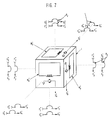
- Fig. 7 illustrates a magnetometer cube which could be used to practice the present invention.
- Three magnetometers M i x , M i y and M i z include SQUIDs S i x , S i y and S i z , respectively.
- Three Helmholtz pairs P x , P y and P z are shown which include F x and G x , F y and G y , and F z and G z , respectively.
- the SQUID outputs O i x , O i y and O i z are calculated based on F i x and G i x , F i y and G i y , and F i z and G i z , respectively.
- Fig. 8 illustrates a single axis gradiometer using magnetometer cubes similar to the one shown in Fig. 7.
- the single axis gradiometer illustrated in Fig. 8 includes three magnetometer cubes K, L and M. Each of the magnetometer cubes K, L and M are arranged in a common line.
- Magnetometer cube K includes three magnetometers which each have an associated feedback coil. No gradient coil is associated with any of these three magnetometers, since the magnetometers of magnetometer cube K are average magnetometers.
- Magnetometer cubes L and M include three magnetometers each having an associated feedback coil. However, only the x-magnetometers of each of cubes L and M have an associated gradient coil, since Fig. 8 illustrates only a single-axis gradiometer. Therefore, the gradient may be calculated as follows: where O L X and O M x are the outputs of the X SQUIDs of magnetometers L and M, respectively, and d is the distance between magnetometers L and M.
- a gradiometer which is at least a five axis gradiometer.
- a five axis gradiometer is one which measures at least five of the nine gradients for a magnetic field with respect to an x, y, and z axis as described below. The reasoning for this is as follows: In determining a gradient for a magnetic field with respect to an x, y and z axis (i.e., in three dimensions), nine gradients are involved. These nine gradients are: This is equivalent to: respectively.
- Fig. 9 illustrates a five axis gradiometer according to the present invention.
- the five axis gradiometer includes four magnetometer cubes A, B, C and D arranged in a common plane.
- the Fig. 9 embodiment uses a higher order gradiometer while practicing the present invention by taking the differences between multiple pairs of difference SQUIDs.
- Magnetometer cube A is an average magnetometer cube having three average magnetometers and magnetometer cubes B, C and D are the same as magnetometer cube i shown in Fig. 7.
- the SQUID outputs O A x , O A y and O A z of magnetometer cube A are provided to the associated feedback coils since no gradient coils are connected for the average magnetometers of cube A.
- d is the distance between magnetometer cubes B and D and (d/2) is the vertical distance (i.e., in the Z direction) from the midpoint of the line connecting magnetometer cubes B and D to magnetometer cube C.
- the gradiometer of Fig. 9 provides six of the nine terms of the gradient. The other three terms can easily be calculated.
- vector magnetometers such as, for example, flux gate magnetometers, SQUIDs, etc. It is preferred that SQUIDs be used to practice the present invention since they have a very high sensitivity. However, any type of vector magnetometer may be used to practice the present invention.
Abstract
Description
- The present invention relates to a gradiometer sensor which employs at least three vector magnetometers to measure a magnetic field gradient. More particularly, the present invention relates to a three SQUID (i.e., Superconducting Quantum Interference Device) gradiometer.
- A description of a SQUID device used to sense magnetic fields is given below based on the SQUID device shown in Fig. 1. SQUID 1 comprises a
superconducting loop 2 having at least one weak link (e.g., Josephson device J) which can exhibit a Josephson current. SQUID 1 is located near aSQUID input coil 3 which is electrically connected to a pick-up coil 4. - When a change in the magnetic field to be detected occurs through pick-
up coil 4, a circulating current Δi will be induced in theSQUID input coil 3. Circulating current Δi produces a magnetic field which couples to theSQUID loop 2 and is detected. Pick-up coil 4 has an inductance Lu which is approximately equal to an inductance Li ofinput coil 3. The inductance Lp of the connecting line betweeninput coil 3 and pick-up coil 4 (i.e., the parasitic inductance) should be very small (i.e., Lp much less than Li). This can be accomplished, for example, as discussed in IBM Technical Disclosure Bulletin, Volume 27, No. 5, October 1984, pages 2822-2823. - Fig. 2 is a graph of voltage vs. modulation current illustrating hysteresis present in a single SQUID device such as the one shown in Fig. 1 (at T=14°K and at a field sweep frequency of approximately 13 Hz).
- The SQUID device shown in Fig. 1 is referred to as an unlocked SQUID because there is no feedback to cancel out the background field. Fig. 3 is a graph of hysteresis (φo) vs. field sweep amplitude (φop-p) of an unlocked SQUID at T=77°K. Fig. 3 illustrates that, as the sweep of the applied magnetic field increases, the hysteresis of the unlocked single SQUID device will also increase.
- Therefore, SQUIDs have been "locked up" by providing feedback in order to prevent hysteresis. This is accomplished by providing feedback so that the value of the magnetic field which the SQUID sees is kept constant (i.e., the SQUID never sees a change in the magnetic field). A change in magnetic field produces a correction current which in turn produces an equal and opposite field. Such an arrangement of "locking up" SQUIDs is illustrated in Fig. 4.
- A magnetic field gradient may be measured by a device which uses the output of two magnetometers separated at a distance d apart from each other. Fig. 4 illustrates such a magnetic field gradient measuring device (i.e., gradiometer). The gradiometer illustrated in Fig. 4 is a two SQUID gradiometer (known in the art as a Bare SQUID Gradiometer). Each SQUID 6a and 6b measures the magnetic field at its respective location.
Amplifiers 9a, 9b,feedback coils 7a, 7b andresistors 8a, 8b (each having the same resistance RF) are used to provide a correction current producing a field equal to and opposite that of the magnetic field. Electronic voltages 'BL' and 'BR' are supplied as outputs corresponding to the magnetic field at each ofSQUIDs 6a and 6b, respectively. The difference between these outputs of SQUIDs 6a and 6b is taken electronically to form the gradient. Thus, the gradient is equal to:
- Such a two SQUID gradiometer is easy to make, has good balance and low hysteresis. However, this type of gradiometer is seldom used because the large common mode signal of the two magnetometers (from the non-gradient terms in the magnetic field) requires an almost impossible degree of common mode rejection (1 part in 10⁹) of an amplifier taking the difference in the outputs between the two SQUIDs. That is, the gradiometer of Fig. 4 is virtually impossible to operate due to the difficulty of electrically detecting a small gradient in the presence of a very large background magnetic field due to the earth's magnetic field. The gradiometer of Fig. 4 attempts to subtract two very large numbers to provide a relatively very small number as the gradient, for example, a ratio of the gradient to the background field of approximately 1:10⁹.
- The electronics associated with such a gradiometer must detect the difference between two magnetic fields where the average background field is very large. This requires the electronics to detect an extremely small signal difference in the presence of a very large signal, which is very difficult and very costly.
- Fig. 5 illustrates a single SQUID thin film gradiometer.
Reference numbers Reference numeral 113 represents the input coil andreference numeral 114 represents a washer-type SQUID. The thin film pick-up coils 
- The currents produced in each of the thin film pick-
up coils 
- A thin film gradiometer such as the one illustrated in Fig. 5 is easy to make and has a very well known design when fabricated from low Tc superconductive materials. However, when it is fabricated from high Tc superconductive materials, the Fig. 5 gradiometer exhibits excessive hysteresis and is very hard to make due to the difficulties associated with high Tc thin film crossover and
planar input coil 113. Therefore, it is not advantageous to use the thin film gradiometer of Fig. 5 when fabrication is made using high Tc superconductive materials. - Given the problems in the prior art, an object of the present invention is to provide a gradiometer which does not exhibit hysteresis, which can be fabricated easily and inexpensively with both high Tc and low Tc superconductive materials, and which provides a high sensitivity.
- An "average" magnetometer is rigidly mounted to the difference magnetometers. The average magnetometer provides a signal via feedback coils to cancel background magnetic fields from outputs of the difference magnetometers. Thus, it is not necessary to subtract large voltages to provide a small gradient. Two gradient field signals which do not include the large background magnetic field are subtracted from each other. Thus, a high sensitivity may be obtained by a system which is very inexpensive. The gradiometer is particularly advantageous when high Tc superconductive materials are used for fabrication. Higher order gradiometers can be built using an average magnetometer cube and a plurality of difference magnetometer cubes.
- Other features and advantages of the present invention will be apparent from the following description taken in connection with the accompanying drawings, wherein;
- Fig. 1
- illustrates a single unlocked SQUID device;
- Fig. 2
- is a voltage vs. modulation current graph used to illustrate hysteresis present in a single unlocked SQUID device such as the one illustrated in Fig. 1;
- Fig. 3
- is a hysteresis vs. field sweep amplitude graph of an unlocked SQUID device;
- Fig. 4
- illustrates a two SQUID gradiometer (or Bare SQUID gradiometer) used to measure a magnetic field gradient;
- Fig. 5
- illustrates a single SQUID thin film gradiometer;
- Fig. 6
- illustrates a three SQUID gradiometer in one axis according to the present invention;
- Fig. 7
- illustrates a magnetometer cube which could be used to practice the present invention;
- Fig. 8
- illustrates a one axis gradiometer according to the present invention using magnetometer cubes similar to the one shown in Fig. 7; and
- Fig. 9
- illustrates a five axis gradiometer according to the present invention using magnetometer cubes such as the one shown in Fig. 7.
- Fig. 6 illustrates a three SQUID gradiometer in one axis according to one aspect of the present invention. The gradiometer includes three
SQUIDs amplifiers resistor 50.SQUIDs SQUID 13 is an average SQUID used to cancel out the background magnetic field (e.g., from the earth's magnetic field) indifference SQUIDs difference SQUIDs -
Average SQUID magnetometer 13 is rigidly mounted to the twodifference SQUIDs SQUIDs SQUID 11 has an associatedfeedback coil 21 and agradient coil 31 whileSQUID 12 has an associatedfeedback coil 22 and agradient coil 32. -
Average SQUID magnetometer 13 is operated similarly to magnetometers (SQUIDs) 11 and 12. However, the DC portion of the modulation field forSQUID 13 is applied to all threeSQUIDs Amplifier 43 is used to apply a magnetic field opposite that of the background magnetic field measured bySQUID 13. Therefore, coils 21, 22 and 23 are used to subtract the background magnetic field fromSQUID -
Difference SQUIDs difference SQUID average SQUID 13. This is due to the cancellation of the uniform field variations each of thedifference SQUIDs average SQUID 13. - The field gradient measured by the gradiometer of Fig. 6 is obtained by simply subtracting the two
difference SQUID - A degree of imbalance usual for thin film gradiometers could be obtained by this system (for example, one part in 10,000). Additionally, the usual techniques of adaptive balancing could be used to achieve a balance of one part per billion. If single level SQUIDs utilizing weak links for the Josephson elements are used, the intrinsic balance in all directions would be excellent since no cross-overs are necessary in this system. This system would be very advantageous using high Tc superconductive elements since single level SQUIDs utilizing weak links for the Josephson elements are very common with high Tc superconductive materials.
- The arrangement shown in Fig. 6 locks up the feedback coils, the gradient coils and the SQUIDs so that no hysteresis is exhibited in the system. Also, an inexpensive gradiometer may be fabricated using either low Tc or high Tc superconductors.
- Using the additional
average magnetometer 13 and the feedback loops in the Fig. 6 gradiometer to couple the SQUID outputs (as opposed to the Fig. 4 gradiometer) yields a result in which the magnetic fields are subtracted prior to developing the difference signal in the SQUID sensor. Without using average SQUID 13 (as in the Fig. 4 gradiometer), the associated electronics would have to detect the difference between two magnetic fields where the average background field was extremely large. The electronics would be required to detect an extremely small signal difference in the presence of two very large signals. This is very difficult and very costly. Thus, by subtracting only the portion of the magnetic fields excluding the background magnetic fields (as opposed to subtracting voltages as done in Fig. 4), the burden on the associated electronics is less and the sensitivity of the gradiometer is much greater. The accuracy of the subtraction (or the balance) only depends on the particular geometry used and could be one part in 10⁶, or better. When relying only on the electronics to detect the difference signal, the sensitivity is much less (e.g., one part in 10⁵). - A major advantage of the Fig. 6 design is that excellent gradient sensitivity may be achieved without hysteresis induced error from using the SQUID and coils.
- Three SQUID gradiometers such as the one shown in Fig. 6 will not only be useful in geological operations such as those used to locate oil, but will also be useful in medical applications since the only physical constraint on the relative locations of the SQUIDs is that they be rigidly mounted together and that the planes of each SQUID loop are parallel. Thus, almost any gradient may be measured with a compact sensor design. Additionally, an array of SQUIDs may be fed with an average magnetometer according to the present invention.
-
Average SQUID magnetometer 13 may be a SQUID but is not required to be so. The present invention may be practiced using any kind of vector magnetometer in place ofaverage SQUID magnetometer 13. - In fact, none of
SQUIDs Difference SQUIDs average SQUID 13 may be any kind of vector magnetometer (e.g., a flux gate magnetometer). Additionally, the coils shown in Fig. 6 need not be superconductive. - In the Fig. 6 embodiment, each of
difference SQUIDs average SQUID 13 has one coil. However, in practice, each of theSQUIDs average SQUID 13 would also have two coils, with one of the coils not being used. Each of the coils used could be a Helmholz pair consisting of two loops wired in series or of a single loop of wire. - Fig. 7 illustrates a magnetometer cube which could be used to practice the present invention. Three magnetometers M


- Fig. 8 illustrates a single axis gradiometer using magnetometer cubes similar to the one shown in Fig. 7. The single axis gradiometer illustrated in Fig. 8 includes three magnetometer cubes K, L and M. Each of the magnetometer cubes K, L and M are arranged in a common line. Magnetometer cube K includes three magnetometers which each have an associated feedback coil. No gradient coil is associated with any of these three magnetometers, since the magnetometers of magnetometer cube K are average magnetometers.
- Magnetometer cubes L and M include three magnetometers each having an associated feedback coil. However, only the x-magnetometers of each of cubes L and M have an associated gradient coil, since Fig. 8 illustrates only a single-axis gradiometer. Therefore, the gradient

may be calculated as follows:
where O

- However, it is advantageous to provide a gradiometer which is at least a five axis gradiometer. A five axis gradiometer is one which measures at least five of the nine gradients for a magnetic field with respect to an x, y, and z axis as described below. The reasoning for this is as follows:
In determining a gradient for a magnetic field with respect to an x, y and z axis (i.e., in three dimensions), nine gradients are involved. These nine gradients are:
This is equivalent to:
respectively. - However, all nine of these gradients need not be specifically measured by a gradiometer. First, it is known that ∇ H = 0.
- It therefore follows that:

Therefore, only two of
must actually be determined since the other one can be calculated once the other two are known. - Second, it is known that ∇ x H ≈ 0. For purposes of the present invention, however, it may be assumed that ∇ x H = 0.
Therefore,
- Therefore, only one of the two terms from each of these equations must be measured since the terms in the same equation are equal to each other.
- Once two terms of the first equation and one term of each of the last three equations are known, all nine terms may be calculated. Therefore, it would be advantageous to have at least a five axis gradiometer so that all nine terms may be determined.
- Fig. 9 illustrates a five axis gradiometer according to the present invention. The five axis gradiometer includes four magnetometer cubes A, B, C and D arranged in a common plane. The Fig. 9 embodiment uses a higher order gradiometer while practicing the present invention by taking the differences between multiple pairs of difference SQUIDs.
- Magnetometer cube A is an average magnetometer cube having three average magnetometers and magnetometer cubes B, C and D are the same as magnetometer cube i shown in Fig. 7. The SQUID outputs O


- The following six gradient terms may be measured by the five axis gradiometer of Fig. 9, where d is the distance between magnetometer cubes B and D and (d/2) is the vertical distance (i.e., in the Z direction) from the midpoint of the line connecting magnetometer cubes B and D to magnetometer cube C.

- Therefore, the gradiometer of Fig. 9 provides six of the nine terms of the gradient. The other three terms can easily be calculated.
- The present invention has been described as set forth above using vector magnetometers such as, for example, flux gate magnetometers, SQUIDs, etc. It is preferred that SQUIDs be used to practice the present invention since they have a very high sensitivity. However, any type of vector magnetometer may be used to practice the present invention.
Claims (15)
- A gradiometer for measuring a magnetic field gradient, comprising:
a plurality of difference magnetometers (11, 12) each producing an output;
an average magnetometer (13) rigidly mounted to said plurality of difference magnetometers (11, 12), said average magnetometer (13) cancelling a background magnetic field from respective outputs of said plurality of difference magnetometers (11, 12) to produce a plurality of cancelled different magnetometer outputs; and
means for providing said magnetic field gradient by performing magnetic subtraction on said plurality of cancelled difference magnetometer outputs. - A gradiometer as claimed in claim 1, wherein said difference magnetometers (11, 12) are Superconducting Quantum Interference Devices (SQUIDs).
- A gradiometer as claimed in claim 1 or 2, wherein said average magnetometer (13) is a Superconducting Quantum Interference Device (SQUID).
- A gradiometer as claimed in any of the above claims, wherein said average magnetometer (13) provides a feedback signal to cancel said background magnetic field.
- A gradiometer as claimed in any of the above claims, wherein said SQUIDs include Josephson elements having weak links.
- A gradiometer as claimed in claims 2-5, wherein high Tc superconductive materials are used for fabricating said SQUIDs.
- A gradiometer as claimed in any of the above claims, wherein a number of said difference magnetometers (11, 12) is two.
- A gradiometer as claimed in any of the above claims, wherein superconducting loops of each of said magnetometers (11, 12, 13) are parallel to each other.
- A gradiometer as claimed in claim 1, further comprising a feedback coil (21, 22, 23) associated with each of said difference magnetometers (11, 12) and said average magnetometer (13) wherein said feedback coils (21, 22, 23) are used to cancel said background magnetic field.
- A gradiometer as claimed in claim 1, wherein each of said difference magnetometers (11, 12) and said average magnetometer (13) is a magnetometer cube provided with a first magnetometer, a second magnetometer and a third magnetometer on respective non-parallel sides of said magnetometer cube.
- A gradiometer as claimed in claim 10, wherein a number of said difference magnetometer cubes is three.
- A gradiometer as claimed in claim 11, wherein said three difference magnetometer cubes and said average magnetometer cube are all situated in a common plane.
- A gradiometer as claimed in claim 10, wherein a number of said difference magnetometer cubes is two.
- A gradiometer as claimed in claim 13, wherein said two difference magnetometer cubes and said average magnetometer cube are all situated in a common line.
- A gradiometer as claimed in any of the above claims, wherein said gradiometer makes at least a five axis measurement of said magnetic field gradient.
Applications Claiming Priority (2)
| Application Number | Priority Date | Filing Date | Title |
|---|---|---|---|
| US594810 | 1990-10-09 | ||
| US07/594,810 US5122744A (en) | 1990-10-09 | 1990-10-09 | Gradiometer having a magnetometer which cancels background magnetic field from other magnetometers |
Publications (2)
| Publication Number | Publication Date |
|---|---|
| EP0481211A2 true EP0481211A2 (en) | 1992-04-22 |
| EP0481211A3 EP0481211A3 (en) | 1993-01-20 |
Family
ID=24380502
Family Applications (1)
| Application Number | Title | Priority Date | Filing Date |
|---|---|---|---|
| EP19910115244 Withdrawn EP0481211A3 (en) | 1990-10-09 | 1991-09-10 | Gradiometer having a magnetometer which cancels background magnetic field from other magnetometers |
Country Status (3)
| Country | Link |
|---|---|
| US (1) | US5122744A (en) |
| EP (1) | EP0481211A3 (en) |
| JP (1) | JPH0711563B2 (en) |
Cited By (16)
| Publication number | Priority date | Publication date | Assignee | Title |
|---|---|---|---|---|
| EP0560621A2 (en) * | 1992-03-13 | 1993-09-15 | General Electric Company | System and method for noiseless measurement of a biomagnetic field |
| GB2283823A (en) * | 1993-11-10 | 1995-05-17 | Ultra Electronics Ltd | Measurement of alternating magnetic fields in presence of steady magnetic field e.g. earth's field |
| WO1996032655A1 (en) * | 1995-04-13 | 1996-10-17 | Forschungszentrum Jülich GmbH | Rf squid gradiometer with resonant flux-focusing structure |
| WO1997008564A1 (en) * | 1995-08-28 | 1997-03-06 | Josef Constantin Szeles | Nuclear magnetic resonance imaging process and device |
| DE19733920A1 (en) * | 1997-08-06 | 1999-02-25 | Forschungszentrum Juelich Gmbh | Device for suppressing interference signals with frequency-dependent adaptation |
| EP0917441A1 (en) * | 1996-06-25 | 1999-05-26 | Quantum Magnetics, Inc. | Ferromagnetic foreign body screening method and apparatus |
| EP0982597A2 (en) * | 1998-08-28 | 2000-03-01 | Neuromag Oy | Method and apparatus for eliminating background interference signals from multichannel detector arrays |
| US6337567B1 (en) * | 1999-04-22 | 2002-01-08 | Lg Electronics Inc. | Apparatus and method for measuring second-order gradient of magnetic field using super conductor quantum interference device |
| US6496713B2 (en) | 1996-06-25 | 2002-12-17 | Mednovus, Inc. | Ferromagnetic foreign body detection with background canceling |
| WO2005078467A1 (en) * | 2004-02-13 | 2005-08-25 | Elekta Ab (Publ) | A method for interference suppression in a measuring device |
| US6965792B2 (en) | 1996-06-25 | 2005-11-15 | Mednovus, Inc. | Susceptometers for foreign body detection |
| US7047059B2 (en) | 1998-08-18 | 2006-05-16 | Quantum Magnetics, Inc | Simplified water-bag technique for magnetic susceptibility measurements on the human body and other specimens |
| US7466132B2 (en) | 2002-02-06 | 2008-12-16 | The Regents Of The University Of California | Squid detected NMR and MRI at ultralow fields |
| US7672707B2 (en) * | 2003-06-11 | 2010-03-02 | Japan Science And Technology Agency | Sensor for magnetoencephalography meter and supermultichannel magnetoencephalography meter system using the same |
| WO2012172435A2 (en) * | 2011-05-13 | 2012-12-20 | Rampart Detection Systems Ltd. | Transverse electromagnetic gradiometer |
| CN109839666A (en) * | 2019-03-05 | 2019-06-04 | 中国科学院遥感与数字地球研究所 | The full tensor magnetic gradient data collection system of aviation superconduction and method based on NI cRIO |
Families Citing this family (30)
| Publication number | Priority date | Publication date | Assignee | Title |
|---|---|---|---|---|
| DE4227876A1 (en) * | 1992-08-22 | 1994-02-24 | Philips Patentverwaltung | Circuit arrangement for operating a SQUID, in particular a DC SQUID |
| US5469057A (en) * | 1994-03-08 | 1995-11-21 | University Of New Mexico | Method and apparatus for extending the dynamic range of DC-squid measurements using a flux tracking loop |
| US5786690A (en) * | 1994-08-18 | 1998-07-28 | International Business Machines Corporation | High resolution three-axis scanning squid microscope having planar solenoids |
| US5657756A (en) * | 1995-06-07 | 1997-08-19 | Ctf Systems Inc. | Method and systems for obtaining higher order gradiometer measurements with lower order gradiometers |
| US5642045A (en) * | 1995-08-18 | 1997-06-24 | International Business Machines Corporation | Magnetic field gradiometer with improved correction circuits |
| JP2001505071A (en) * | 1996-03-27 | 2001-04-17 | メドネティックス・アクチエンゲゼルシヤフト | Apparatus and method for position measurement |
| KR100198534B1 (en) * | 1996-05-02 | 1999-06-15 | 구자홍 | The detecting apparatus of magneticfield using two-squid |
| GB9704911D0 (en) * | 1997-03-10 | 1997-04-30 | Secr Defence | A magnetic gradiometer |
| GB2337128B (en) * | 1997-03-10 | 2001-12-05 | Secr Defence | Magnetic gradiometer |
| US6008641A (en) * | 1997-10-22 | 1999-12-28 | The United States Of America As Represented By The Secretary Of The Navy | Method using corrective factors for aligning a magnetic gradiometer |
| US5990679A (en) * | 1997-10-22 | 1999-11-23 | The United States Of America As Represented By The Secretary Of The Navy | Method using corrective factors for determining a magnetic gradient |
| GB9813889D0 (en) * | 1998-06-27 | 1998-08-26 | Secr Defence | Apparatus for detecting metals |
| KR100400755B1 (en) * | 2001-11-08 | 2003-10-08 | 엘지전자 주식회사 | SQUID sensor using secondary sensor |
| US7002341B2 (en) * | 2002-08-28 | 2006-02-21 | Vanderbilt University | Superconducting quantum interference apparatus and method for high resolution imaging of samples |
| JP4263544B2 (en) * | 2003-06-23 | 2009-05-13 | 株式会社日立ハイテクノロジーズ | Magnetic field measuring device |
| US20060197523A1 (en) * | 2005-03-04 | 2006-09-07 | Assurance Technology Corporation | Magnetic screening system |
| US20120041297A1 (en) * | 2009-02-06 | 2012-02-16 | Baylor College Of Medicine | Real-time magnetic dipole detection and tracking |
| US8378667B2 (en) * | 2009-05-22 | 2013-02-19 | Tdw Delaware Inc. | System and method for detecting the passage of an object in pipeline including shielded magnetometer and a microcontroller with adaptive thresholding detection means |
| US8314608B2 (en) | 2010-06-30 | 2012-11-20 | Hall David R | Method of determining distance to a ferrous material |
| UA102163C2 (en) * | 2012-02-02 | 2013-06-10 | Владимир Николаевич Сосницкий | Device for compensation of electromagnetic interferences at measurement of bio-magnetic signals |
| JP6255902B2 (en) * | 2013-10-30 | 2018-01-10 | Tdk株式会社 | Magnetic field detector |
| CN104880680B (en) * | 2014-02-28 | 2017-12-05 | 中国科学院上海微系统与信息技术研究所 | Superconducting quantum interference device magnetic sensor-based system |
| US10228398B2 (en) | 2015-04-02 | 2019-03-12 | Rosemount Aerospace Inc. | System and method for minimizing magnetic field effect on an isolated magnetometer |
| US9955912B2 (en) | 2015-07-14 | 2018-05-01 | Getchell Technologies Llc | Magnet-based monitoring system |
| US10338261B2 (en) | 2015-09-16 | 2019-07-02 | Raytheon Company | Measurement of magnetic field gradients |
| JP2017062122A (en) * | 2015-09-23 | 2017-03-30 | 国立大学法人名古屋大学 | Magnetic field detector |
| US11134877B2 (en) * | 2017-08-09 | 2021-10-05 | Genetesis, Inc. | Biomagnetic detection |
| US10514429B2 (en) | 2018-05-03 | 2019-12-24 | United States Of America As Represented By The Secretary Of The Navy | SQUID array planar and axial gradiometer |
| US11585869B2 (en) | 2019-02-08 | 2023-02-21 | Genetesis, Inc. | Biomagnetic field sensor systems and methods for diagnostic evaluation of cardiac conditions |
| US11776736B2 (en) * | 2019-12-18 | 2023-10-03 | United States Of America As Represented By The Secretary Of The Navy | Electronic package for an electrically small device with integrated magnetic field bias |
Citations (4)
| Publication number | Priority date | Publication date | Assignee | Title |
|---|---|---|---|---|
| US2620381A (en) * | 1947-05-27 | 1952-12-02 | Fred M Mayes | Magnetometer gradiometer apparatus and method |
| US4489274A (en) * | 1980-12-10 | 1984-12-18 | The United States Of America As Represented By The Secretary Of The Navy | Rotating SQUID magnetometers and gradiometers |
| JPS6058565A (en) * | 1983-09-12 | 1985-04-04 | Tech Res & Dev Inst Of Japan Def Agency | Moving high sensitivity magnetic gradient measuring system |
| FR2560388A1 (en) * | 1980-03-17 | 1985-08-30 | Commissariat Energie Atomique | GRADIENTMETER WITH THIN MAGNETIC LAYER |
Family Cites Families (11)
| Publication number | Priority date | Publication date | Assignee | Title |
|---|---|---|---|---|
| US3110282A (en) * | 1960-08-24 | 1963-11-12 | Friedrich M O Foerster | Degaussing control |
| US3311821A (en) * | 1962-12-11 | 1967-03-28 | Canadair Ltd | Apparatus for automatically compensating the output of a magnetic field sensing device for the effects of interfering magnetic fields |
| CA1140214A (en) * | 1980-01-29 | 1983-01-25 | Malcolm E. Bell | Multisensor magnetometers |
| US4386318A (en) * | 1980-09-26 | 1983-05-31 | Her Majesty The Queen In Right Of Canada, As Represented By The Minister Of National Defence | Method and apparatus to compensate a gradiometer having first and second unwanted terms |
| US4394831A (en) * | 1981-02-12 | 1983-07-26 | Honeywell Inc. | Helmet metal mass compensation for helmet-mounted sighting system |
| JPS58154615A (en) * | 1982-03-10 | 1983-09-14 | Copal Co Ltd | Magnetic detector |
| CA1208292A (en) * | 1982-08-27 | 1986-07-22 | Malcolm E. Bell | Magnetometer with precision aligned sensors |
| US4528506A (en) * | 1982-11-23 | 1985-07-09 | The United States Of America As Represented By The Secretary Of The Air Force | Ferromagnetic resonance probe liftoff suppression apparatus |
| FR2553520B1 (en) * | 1983-10-14 | 1986-04-11 | Thomson Csf | GONIOTELEMETRY SYSTEM |
| FR2558599B1 (en) * | 1984-01-24 | 1986-08-01 | Thomson Csf | METHOD AND DEVICE FOR AUTOMATIC COMPENSATION OF MECHANICAL ERRORS OF A MAGNETIC GRADIENTMETER |
| US4801883A (en) * | 1986-06-02 | 1989-01-31 | The Regents Of The University Of California | Integrated-circuit one-way isolation coupler incorporating one or several carrier-domain magnetometers |
-
1990
- 1990-10-09 US US07/594,810 patent/US5122744A/en not_active Expired - Lifetime
-
1991
- 1991-09-10 EP EP19910115244 patent/EP0481211A3/en not_active Withdrawn
- 1991-10-03 JP JP28196091A patent/JPH0711563B2/en not_active Expired - Fee Related
Patent Citations (4)
| Publication number | Priority date | Publication date | Assignee | Title |
|---|---|---|---|---|
| US2620381A (en) * | 1947-05-27 | 1952-12-02 | Fred M Mayes | Magnetometer gradiometer apparatus and method |
| FR2560388A1 (en) * | 1980-03-17 | 1985-08-30 | Commissariat Energie Atomique | GRADIENTMETER WITH THIN MAGNETIC LAYER |
| US4489274A (en) * | 1980-12-10 | 1984-12-18 | The United States Of America As Represented By The Secretary Of The Navy | Rotating SQUID magnetometers and gradiometers |
| JPS6058565A (en) * | 1983-09-12 | 1985-04-04 | Tech Res & Dev Inst Of Japan Def Agency | Moving high sensitivity magnetic gradient measuring system |
Non-Patent Citations (2)
| Title |
|---|
| PATENT ABSTRACTS OF JAPAN vol. 9, no. 190 (P-378)(1913) 7 August 1985 & JP-A-60 58 565 ( BOEICHO GIJUTSI KENKYU HONBU ) * |
| SENSORS AND ACTUATORS A vol. A21, no. 1/3, 1 February 1990, LAUSANNE CH M.DECROUX 'high tc superconducting based sensors' * |
Cited By (27)
| Publication number | Priority date | Publication date | Assignee | Title |
|---|---|---|---|---|
| EP0560621A3 (en) * | 1992-03-13 | 1994-08-10 | Gen Electric | System and method for noiseless measurement of a biomagnetic field |
| EP0560621A2 (en) * | 1992-03-13 | 1993-09-15 | General Electric Company | System and method for noiseless measurement of a biomagnetic field |
| GB2283823B (en) * | 1993-11-10 | 1997-04-02 | Ultra Electronics Ltd | Measurement of alternating magnetic fields |
| GB2283823A (en) * | 1993-11-10 | 1995-05-17 | Ultra Electronics Ltd | Measurement of alternating magnetic fields in presence of steady magnetic field e.g. earth's field |
| WO1996032655A1 (en) * | 1995-04-13 | 1996-10-17 | Forschungszentrum Jülich GmbH | Rf squid gradiometer with resonant flux-focusing structure |
| AT406092B (en) * | 1995-08-28 | 2000-02-25 | Szeles Josef Constantin Dr | METHOD AND DEVICE FOR FORMING AN IMAGE WITH NUCLEAR SPIN RESONANCE |
| US6031373A (en) * | 1995-08-28 | 2000-02-29 | Josef Constantin Szeles | Nuclear magnetic resonance imaging process and device |
| WO1997008564A1 (en) * | 1995-08-28 | 1997-03-06 | Josef Constantin Szeles | Nuclear magnetic resonance imaging process and device |
| EP0917441A1 (en) * | 1996-06-25 | 1999-05-26 | Quantum Magnetics, Inc. | Ferromagnetic foreign body screening method and apparatus |
| EP0917441A4 (en) * | 1996-06-25 | 1999-09-01 | Quantum Magnetics Inc | Ferromagnetic foreign body screening method and apparatus |
| US6496713B2 (en) | 1996-06-25 | 2002-12-17 | Mednovus, Inc. | Ferromagnetic foreign body detection with background canceling |
| US6965792B2 (en) | 1996-06-25 | 2005-11-15 | Mednovus, Inc. | Susceptometers for foreign body detection |
| US6418335B2 (en) | 1996-06-25 | 2002-07-09 | Mednovus, Inc. | Ferromagnetic foreign body detection using magnetics |
| DE19733920A1 (en) * | 1997-08-06 | 1999-02-25 | Forschungszentrum Juelich Gmbh | Device for suppressing interference signals with frequency-dependent adaptation |
| US7047059B2 (en) | 1998-08-18 | 2006-05-16 | Quantum Magnetics, Inc | Simplified water-bag technique for magnetic susceptibility measurements on the human body and other specimens |
| US6538436B1 (en) | 1998-08-28 | 2003-03-25 | Neuromag Oy | Method and apparatus for eliminating background interference signals from multichannel signal measurements |
| EP0982597A2 (en) * | 1998-08-28 | 2000-03-01 | Neuromag Oy | Method and apparatus for eliminating background interference signals from multichannel detector arrays |
| EP0982597A3 (en) * | 1998-08-28 | 2009-01-28 | ELEKTA AB (publ.) | Method and apparatus for eliminating background interference signals from multichannel detector arrays |
| US6337567B1 (en) * | 1999-04-22 | 2002-01-08 | Lg Electronics Inc. | Apparatus and method for measuring second-order gradient of magnetic field using super conductor quantum interference device |
| US7466132B2 (en) | 2002-02-06 | 2008-12-16 | The Regents Of The University Of California | Squid detected NMR and MRI at ultralow fields |
| US7672707B2 (en) * | 2003-06-11 | 2010-03-02 | Japan Science And Technology Agency | Sensor for magnetoencephalography meter and supermultichannel magnetoencephalography meter system using the same |
| WO2005078467A1 (en) * | 2004-02-13 | 2005-08-25 | Elekta Ab (Publ) | A method for interference suppression in a measuring device |
| US7649351B2 (en) | 2004-02-13 | 2010-01-19 | Elekta Ab (Publ) | Method for interference suppression in a measuring device |
| WO2012172435A2 (en) * | 2011-05-13 | 2012-12-20 | Rampart Detection Systems Ltd. | Transverse electromagnetic gradiometer |
| WO2012172435A3 (en) * | 2011-05-13 | 2013-04-25 | Rampart Detection Systems Ltd. | A transverse electromagnetic gradiometer including an electromagnetometer having a longitudinal slit in the electrostatic shield |
| CN109839666A (en) * | 2019-03-05 | 2019-06-04 | 中国科学院遥感与数字地球研究所 | The full tensor magnetic gradient data collection system of aviation superconduction and method based on NI cRIO |
| CN109839666B (en) * | 2019-03-05 | 2020-12-04 | 中国科学院遥感与数字地球研究所 | NI cRIO-based aviation superconducting full-tensor magnetic gradient data acquisition system and method |
Also Published As
| Publication number | Publication date |
|---|---|
| EP0481211A3 (en) | 1993-01-20 |
| US5122744A (en) | 1992-06-16 |
| JPH0711563B2 (en) | 1995-02-08 |
| JPH04264281A (en) | 1992-09-21 |
Similar Documents
| Publication | Publication Date | Title |
|---|---|---|
| US5122744A (en) | Gradiometer having a magnetometer which cancels background magnetic field from other magnetometers | |
| US6690162B1 (en) | Device for high-resolution measurement of magnetic fields | |
| Wynn et al. | Advanced superconducting gradiometer/magnetometer arrays and a novel signal processing technique | |
| US6339328B1 (en) | Magnetic gradiometer incorporating global feedback | |
| US4591787A (en) | Multi-channel device with SQUIDS and superconducting gradiometers for the measurement of weak magnetic fields produced by various field sources | |
| JP3204542B2 (en) | Magnetic field source measurement device | |
| US4613817A (en) | Superconducting gradiometer coil system for an apparatus for the multi-channel measurement of weak nonstationary magnetic fields | |
| US4320341A (en) | Method and apparatus for balancing the magnetic field detecting loops of a cryogenic gradiometer using trimming coils and superconducting disks | |
| US5642045A (en) | Magnetic field gradiometer with improved correction circuits | |
| US7508202B2 (en) | Method and apparatus for magnetic field detection | |
| US6665552B2 (en) | Gradiometer integrating pickup coils and magnetic field measurement system | |
| US6154026A (en) | Asymmetric planar gradiometer for rejection of uniform ambient magnetic noise | |
| Opfer et al. | A superconducting second-derivative gradiometer | |
| AU4756800A (en) | Measurement of magnetic fields using a string fixed at both ends | |
| US5053706A (en) | Compact low-distortion squid magnetometer | |
| US5289121A (en) | Composite pickup coil for measurement of magnetic field components in a superconducting quantum interference device | |
| US5252921A (en) | Noise canceling high-sensitive magnetometer | |
| Kittel et al. | High T c superconducting second-order gradiometer | |
| Eulenburg et al. | Highly balanced long-baseline single-layer high-T c superconducting quantum interference device gradiometer | |
| Lee et al. | Direct-coupled second-order superconducting quantum interference device gradiometer from single layer of high temperature superconductor | |
| Keenan et al. | Mobile magnetic anomaly detection using a field-compensated high-Tc single layer SQUID gradiometer | |
| JPH05232202A (en) | Software gradiometer | |
| Kouznetsov et al. | High T c superconducting asymmetric gradiometer for biomagnetic applications | |
| CN104220890B (en) | The device of compensation electromagnetic interference in biological magnetic-measurement | |
| JP3156396B2 (en) | Differential SQUID magnetometer and biomagnetic field measurement device using the same |
Legal Events
| Date | Code | Title | Description |
|---|---|---|---|
| PUAI | Public reference made under article 153(3) epc to a published international application that has entered the european phase |
Free format text: ORIGINAL CODE: 0009012 |
|
| AK | Designated contracting states |
Kind code of ref document: A2 Designated state(s): DE FR GB |
|
| PUAL | Search report despatched |
Free format text: ORIGINAL CODE: 0009013 |
|
| AK | Designated contracting states |
Kind code of ref document: A3 Designated state(s): DE FR GB |
|
| 17P | Request for examination filed |
Effective date: 19930918 |
|
| 17Q | First examination report despatched |
Effective date: 19950712 |
|
| STAA | Information on the status of an ep patent application or granted ep patent |
Free format text: STATUS: THE APPLICATION IS DEEMED TO BE WITHDRAWN |
|
| 18D | Application deemed to be withdrawn |
Effective date: 19960123 |