EP0480541A2 - A method of automatically milking animals and an implement for performing same - Google Patents
A method of automatically milking animals and an implement for performing same Download PDFInfo
- Publication number
- EP0480541A2 EP0480541A2 EP91202804A EP91202804A EP0480541A2 EP 0480541 A2 EP0480541 A2 EP 0480541A2 EP 91202804 A EP91202804 A EP 91202804A EP 91202804 A EP91202804 A EP 91202804A EP 0480541 A2 EP0480541 A2 EP 0480541A2
- Authority
- EP
- European Patent Office
- Prior art keywords
- teat cup
- robot arm
- teat
- milking
- implement
- Prior art date
- Legal status (The legal status is an assumption and is not a legal conclusion. Google has not performed a legal analysis and makes no representation as to the accuracy of the status listed.)
- Granted
Links
Images


Classifications
-
- A—HUMAN NECESSITIES
- A01—AGRICULTURE; FORESTRY; ANIMAL HUSBANDRY; HUNTING; TRAPPING; FISHING
- A01J—MANUFACTURE OF DAIRY PRODUCTS
- A01J5/00—Milking machines or devices
- A01J5/017—Automatic attaching or detaching of clusters
- A01J5/0175—Attaching of clusters
-
- G—PHYSICS
- G01—MEASURING; TESTING
- G01S—RADIO DIRECTION-FINDING; RADIO NAVIGATION; DETERMINING DISTANCE OR VELOCITY BY USE OF RADIO WAVES; LOCATING OR PRESENCE-DETECTING BY USE OF THE REFLECTION OR RERADIATION OF RADIO WAVES; ANALOGOUS ARRANGEMENTS USING OTHER WAVES
- G01S15/00—Systems using the reflection or reradiation of acoustic waves, e.g. sonar systems
- G01S15/02—Systems using the reflection or reradiation of acoustic waves, e.g. sonar systems using reflection of acoustic waves
- G01S15/06—Systems determining the position data of a target
- G01S15/42—Simultaneous measurement of distance and other co-ordinates
-
- G—PHYSICS
- G01—MEASURING; TESTING
- G01S—RADIO DIRECTION-FINDING; RADIO NAVIGATION; DETERMINING DISTANCE OR VELOCITY BY USE OF RADIO WAVES; LOCATING OR PRESENCE-DETECTING BY USE OF THE REFLECTION OR RERADIATION OF RADIO WAVES; ANALOGOUS ARRANGEMENTS USING OTHER WAVES
- G01S15/00—Systems using the reflection or reradiation of acoustic waves, e.g. sonar systems
- G01S15/88—Sonar systems specially adapted for specific applications
Landscapes
- Engineering & Computer Science (AREA)
- Remote Sensing (AREA)
- Radar, Positioning & Navigation (AREA)
- Physics & Mathematics (AREA)
- Computer Networks & Wireless Communication (AREA)
- Acoustics & Sound (AREA)
- Life Sciences & Earth Sciences (AREA)
- General Physics & Mathematics (AREA)
- Environmental Sciences (AREA)
- Animal Husbandry (AREA)
- External Artificial Organs (AREA)
- Manipulator (AREA)
- Catching Or Destruction (AREA)
- Orthopedics, Nursing, And Contraception (AREA)
- Farming Of Fish And Shellfish (AREA)
- Medicines Containing Material From Animals Or Micro-Organisms (AREA)
- Toys (AREA)
- Housing For Livestock And Birds (AREA)
- Investigating Or Analysing Biological Materials (AREA)
Abstract
Description
- The present invention relates to a method for automatically milking animals, e.g. cows, in a milking parlour.
- In automating the milking operation, whereby e.g. the milking of cows is effected without the presence of operating staff or the staff has a supervisory function only, it is of prime importance that one of the most critical actions, e.g. the application of the teat cups onto the teats and the removal therefrom, is effected reliably and efficiently.
- In practice, the luring of an animal to be milked to the milking parlour, in particular by providing food therein, has not been found to offer great problems. Once the animal has arrived in the milking parlour, it can be positioned in a normal manner by providing a boundary at the front end of the milking parlour, the animal tending to lean against the boundary so as to reach with its head to a manger located further on. By also limiting the width of the milking parlour, the position of the animal ready to be milked is roughly determined. However, the positions of the teats of the animal's udder are not determined thereby, in particular because the animals never are of a size nor is the positioning of their teats on the udder the same. In addition, the position of the teats is also determined by other circumstances, e.g. the quantity of milk contained in the udder. Moreover, the animal may assume various postures and be moving. In order to determine the position of the teats, it is known to use specific sensor means, with the aid of which the teat cups can be positioned under the respective teats and subsequently be attached thereto.
- The invention has for its object to provide a comparatively cheap method, by means of which the teat cups can be connected to and be removed from the teats of the animal's udder in a reliable and efficient manner.
- To that end, according to the invention, the method of automatically milking animals, e.g. cows, in a milking parlour, is characterized in that the teat cups carried by a robot arm of a milking robot can be moved individually upwardly relative to the robot arm, whereby a vacuum is produced in the teat cup moved upwardly, so that said teat cup can suck to a relevant teat, whereafter the teat cup is released from the robot arm but remains connected therewith via a flexible connecting member, by means of which the teat cup is pulled towards and against the robot arm when the milking flow through said teat cup has ended.
- Because of the limited space under the animal's udder and the fact that the robot arm is brought under the udder starting from a defined position outside the milking parlour, it is preferable that the teats which are in a more rearward position relative to the robot arm are provided with a teat cup before the teats which are in a more nearby position relative to the robot arm. According to the above method, the teat cups which are carried together by a robot arm can be attached individually to the relevant teats. Therefore, it will be favourable that, prior to being moved upwardly, a teat cup is brought under a relevant teat by turning the robot arm from outside the milking parlour to under the animal's udder and by positioning the robot arm therebelow by means of a sensor for establishing the position of the teats. So, it will be possible to control the robot arm in such a manner that, each time when a teat cup has to be attached, this teat cup will be positioned just below the relevant teat.
- The invention furthermore relates to an implement for performing the above method. To that end, the implement comprises a milking parlour and a milking robot with a robot arm carrying teat cups, which robot arm can be turned from outside the milking parlour to under the animal's udder and be positioned therebelow by means of a sensor for establishing the position of the teats and means for individually moving upwardly said teat cups relative to the robot arm, the teat cups being releasable from the robot arm, so that, when a vacuum is produced in a teat cup, the said teat cup can suck to a relevant teat and be released from the robot arm, the implement further comprising a flexible connecting member, forming a flexible connection between the robot arm and a teat cup during milking and being capable of pulling said teat cup towards and against the robot arm when the milking flow through said teat cup has ended. Particularly for each teat cup, the robot arm is provided near its end with an upwardly movable teat cup carrier, against which a teat cup can be pulled by a flexible connecting member. The robot arm can further be provided with drive means and a lever for moving the teat cup carrier upwardly, and with drive means for pulling the flexible connecting member, so that a teat cup, which during milking is remote from the end of the robot arm, can be pulled towards and against the teat cup carrier. The teat cup carrier can be provided with at least one recessed portion, through which the flexible connecting member passes, the said recessed portion being a substantially vertical slot. Further according to the invention, for each teat cup a teat cup holder can be provided, to which a flexible connecting member is connected, whereby a teat cup is connected pivotably to said teat cup holder, the pivoting axis being at an angle with the vertical. In a particular embodiment, the flexible connecting member consists of a wire or rope, e.g. made of a synthetic resin material and/or a metal.
- For a better understanding of the invention and to show how the same may be carried into effect, an embodiment thereof will now be described with reference to the accompanying drawings, in which:
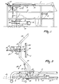
- Figure 1 is a side view of a cow present in a milking parlour;
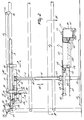
- Figure 2 is, to an enlarged scale, a more detailed part of the side view according to Figure 1;
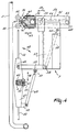
- Figure 3 is a partial plan view taken in the direction of the arrow III in Figure 2;
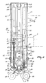
- Figure 4 is a cross-sectional view taken on the line IV-IV in Figure 2;
- Figure 5 is a cross-sectional view in accordance with Figure 4, the robot arm being in the operational position;
- Figure 6 is a horizontal cross-sectional view of part of the robot arm;
- Figure 7 is a partially vertical cross-section through part of the robot arm;
- Figure 8 is a cross-sectional view taken on the line VIII-VIII in Figure 7, and
- Figure 9 is a partial cross-sectional view taken on the line IX-IX in Figure 6.
- In the various drawings, the embodiment is shown only schematically.
- In the side view of the implement of Figure 1 there is shown a cow 1 which is present in the milking parlour, the milking parlour being enclosed by a railing 2 which limits the freedom of movement of the animal 1 in a lateral direction. The milking parlour is entered by the animal from the rear, while a pivotal stop 3 is arranged near the front side, which stop 3 constitutes a boundary for the animal 1 in the forward direction. By providing the front side of the milking parlour with e.g. a feed unit, the animal will advance sufficiently far, i.e. until against the stop 3.
- The milking parlour floor has a recess 4, which is arranged such that the animal will not put her hind feet thereon, e.g. because its bottom extends obliquely inwardly and downwardly, so that the hind legs of the animal are wide apart and on either side of the recess 4. The recess 4 may have a drain for discharging the animal's excrements, if any.
- Once the animal has entered the milking parlour, a
sensor device 5 is pivoted against her rear side, as will be described in further detail with reference to Figure 3. At the side of the milking parlour there is arranged a substantiallyvertical frame beam 6, whichframe beam 6 at its upper end is provided with a longitudinal guide means and to which near its lower end arobot arm 7 is fitted, as will be set out in further detail hereinafter. - Figure 2 shows in greater detail the features shown roughly in Figure 1. Figure 2 shows part of the railing 2, while there is indicated how the
vertical frame beam 6 is capable of moving with respect to the milking parlour in the longitudinal direction as denoted by the arrows 8. For that purpose, the railing 2 is provided with aguide rod 9 along which can move twointerconnected slide blocks slide blocks horizontal frame beam 37 secured to thevertical frame beam 6. Near the floor, theframe beam 6 is guided byguide rail 12, along which thelower portion 13 offrame beam 6 slides. This sliding movement in the longitudinal direction of theframe beams operating cylinder 14, theend 15 of which is connected to the railing 2 via asupport 16 and thepiston rod 17 of which is connected to asupport 19 attached to theframe beam 37. It will be obvious that by operating thecylinder 14, which can be done both pneumatically and hydraulically, there is effected a shift of theframe beams - The
frame beam 37 is furthermore provided with asensor device 5, whichsensor device 5 is shown in plan view in Figure 3. - As is shown in Figure 3, the
sensor device 5 is connected pivotably about apivot pin 20 to asupport 21, whichsupport 21 is attached to theframe beam 37. The pivotal movement of thesensor device 5 is effected by means of anoperating cylinder 22, one end of which is connected to theframe beam 37 and the other end to asupport 23 of thesensor device 5. In the position shown in Figure 3, thesensor device 5 is in the operative position, whilstbroken lines 24 indicate the position of the sensor device when the animal enters the milking parlour. The pivotal movement of thesensor device 5 is indicated by means ofarrows 25. - The
sensor device 5 is fitted with abent frame 26 which constitutes the rear fence of the milking parlour. Theframe 26 comprises control means 27 to which is connected asensor 28, whichsensor 28 is adapted to bear against the rear side of the animal. Thesensor 28 including acushion 36 is connected pivotably about a horizontal pivot pin 29 (see Figure 2) to theframe 26 and is furthermore provided with alever 30 that is connected to thecontrol mechanism 27 via an adjustableintermediate shaft 31. There is also provided aspring 32, whichspring 32 keeps anarm 33 to which thesensor 28 is connected in the position as shown. - The
control mechanism 27 operates theoperating cylinder 14 such that thepiston rod 17 is displaced therein, i.e. theframe beams sensor 28 comes to bear against the rear side of an animal, while thearm 33, thelever 30 and theintermediate shaft 31 tilt in such a manner that thecontrol mechanism 27 fixes theoperating cylinder 14. When the animal moves somewhat to the rear, thereby causing the sensor device 5 (Figure 2) to be moved to the left and the tilt of thearm 33, thelever 30 and theintermediate shaft 31 to be increased still further, thecontrol mechanism 27 operates theoperating cylinder 14 in such a manner that thepiston rod 17 moves to the left, as a result of which the frame beams 6 and 37 move along with the animal to the left. It will be obvious that thus thecontrol mechanism 27 so controls theoperating cylinder 14 that theframe beams control mechanism 27 includes ahandle 34 by means of which, optionally, the displacement of the frame beams can be effected by hand. Optionally, the pressure ofsensor 28 against the rear side of the animal can be adjusted to any desired pressure. As is apparent from Figure 3, thecontrol mechanism 27 is fitted to theframe 26 by means of asupport 35. - A robot arm 7 (Figure 2) is connected slidably in height (arrows 40) to the
frame beam 6. The sliding movement in height is effected by means of an operating cylinder 41 having apiston rod 42, the oneend 43 of which is connected to theframe beams other end 44 of the operating cylinder 41 is connected to aslide block 45 which is capable of moving in height along theframe beam 6 in dependence on the operation of the operating cylinder 41. - The
robot arm 7 is shown in greater detail in Figure 4 (rest position) and Figure 5 (operational position). Therobot arm 7 is connected capable of pivoting about a substantiallyvertical pivot pin 46 to aframe 47 which is attached to theslide block 45. This pivotal movement, which is indicated byarrows 48, is effected by means of anoperating cylinder 49 which has one end connected to asupport 50 of theframe 47. Thepiston rod 51 of thecylinder 49 is connected to asupport 52 which is attached to thefirst position 53 of therobot arm 7. It will be obvious that, by operating the operatingcylinder 49, therobot arm 7 can be pivoted from the rest position (Figure 4) to the operational position (Figure 5) and vice versa. It may be of importance for therobot arm 7 to be fixed under spring load, i.e. in such a manner that it can deflect when e.g. the animal kicks against it. In this embodiment, this can be achieved by constructing the operatingcylinder 49 such that it can spring e.g. by a pneumatic means. - The
robot arm 7 consists of afirst portion 53 and asecond portion 54 which is connected capable of pivoting about apivot pin 55 to the saidfirst portion 53. The pivotal movement about thepivot pin 55 is indicated byarrows 56 and is effected by means of acylinder 58 whoseend 59 is attached to thefirst portion 53 of therobot arm 7 and whosepiston rod 60 is connected to thesecond portion 54 of therobot arm 7. As is apparent from Figures 4 and 5, by means of the operatingcylinder 49, therobot arm 7 can be moved to under the animal present in the milking parlour, thepivot pin 55 being in a central position under the animal, i.e. between the animal's legs. Thereafter, by operating the operatingcylinder 58, thesecond portion 54 of therobot arm 7 can be pivoted about thepivot pin 55 at a desired angle. - The
second portion 54 of therobot arm 7, further details of which are shown in Figures 6, 7, 8 and 9, consists of aportion 61 which is connected pivotably to thefirst portion 53 of therobot arm 7 and aportion 62 which is axially movable relative to theportion 61, as is indicated by thearrows 63. - The
portion 61 is of a substantially hollow construction, so that, in the inserted condition, theportion 62 is partly within theportion 61. Between the mutuallyslidable portions operating cylinder 64, theend 65 of which is connected to theportion 61 of thesecond portion 54 of therobot arm 7. Thepiston rod 66 of the operatingcylinder 64 has itsend 67 connected to theportion 62 of thesecond portion 54 of therobot arm 7. Theportions portion 61 and the guide means 69 to the portion 62 (see also Figure 8). - As is apparent from Figure 8, a set of guide means 68, 69 extends on either side of the
second portion 54 ofrobot arm 7, the guide means 69 being interconnected by aU-shaped frame portion 70 to which furthermore are connected two operatingcylinders milk hose holders - Near the ends of the guide means 69 that are shown at the right-hand side in Figure 7, the said guide means are also interconnected and support a number of component parts which can slide along with the guide means 69 relative to the further portions of the
robot arm 7. These component parts are the detection means 75, theteat cup carriers 76 and the control means therefor. - In this embodiment, the detection means 75 consist in an ultrasonic sensor 77 capable of transmitting an ultrasonic signal in the upward direction, which signal is received after reflection, whereafter the distance to the reflecting object can be calculated, whilst the location of this object can be determined on the basis of the data as to the direction of the transmitted signal. The ultrasonic signal is transmitted upwardly by the sensor 77, whereafter it is reflected in an approximately horizontal direction by a somewhat
concave reflector 78. The use of thisconcave reflector 78 achieves a more directional signal having e.g. a divergence of approximately 4°. Thereflector 78 can be turned about a substantially vertical axis by means of an operatingmotor 79, so that it can perform both a rotational movement and a reciprocating (swinging) one. By performing this movement, a disc-shaped portion of the space, which approximates a plane, can be scanned for the presence of objects. The said plane may be a flat plane located perpendicularly to the rotational axis of thereflector 78, but also a conical plane having this axis as its axis of symmetry. - It will be obvious that the detection means 75 can establish the position of one or more teats of the animal's udder when the
robot arm 7 is at the appropriate level. The detected position of the teat or teats is the position relative to the end of therobot arm 7, so that therefrom it can be derived directly what movements the operatingcylinders teat cup 80 under the relevant teat. During and directly after the end of therobot arm 7 has been moved, the detection means 75 can always track the position of the relevant teat, so that therelevant teat cup 80 is positioned, and remains so, under the teat to which it must be connected. The ultrasonic sensor transmits and receives a signal e.g. sixty times per second, so that it can always be checked whether the teat is already in the proper position relative to therobot arm 7. The use of this mode of direct control enables a very simple and hence cheap robot arm control. - A plurality of teat cups 80 can be arranged to the
robot arm 7, but in principle these teat cups are not connected simultaneously to the relevant teats. Once ateat cup 80 has been moved in the above-described manner to under the teat to which it must be connected, it is moved upwardly and a vacuum is produced therewithin, so that the teat cup sucks to the teat. Thereafter theteat cup 80 is released from therobot arm 7, so that thisrobot arm 7 can move with the object of positioning a subsequent teat cup in the desired place. The following technical means are provided for performing the actions described in the foregoing. - At the end of the
robot arm 7 there is/are provided one or moreteat cup carriers 76, each of which can carry ateat cup 80. Theteat cup 80 is pulled against theteat cup carrier 76 by means of a flexible connecting member in the form of acord 81. In the embodiment shown, the two ends ofcord 81 are connected to theteat cup 80, whilst from its end the cord is passed around aroller 82 and wrapped around aroller 83. Theroller 83 is arranged in theslidable portion 62 of therobot arm 7, as is also the above-mentionedoperating cylinder 72, whilst theroller 82 is arranged at the end ofpiston rod 84 ofcylinder 72. It will be obvious that, when thepiston rod 84 is retracted in thecylinder 72, this has as a result that the ends ofcord 81 are tightened, so that theteat cup 80 connected thereto is clamped against theteat cup carrier 76. However, when the operatingcylinder 72 is operated in such a way that thepiston rod 84 moves therefrom, then theteat cup 80 is no longer clamped against theteat cup carrier 76 and it can move freely relative to therobot arm 7 and be connected to a teat of the udder. At any desired moment, e.g. when the milking procedure has ended or when for any other reason the teat cup is not connected to the teat, theteat cup 80 can be pulled against theteat cup carrier 76 again by operating the operatingcylinder 72. Since theteat cup 80 is connected to thecord 81 in two places, it will always be kept in the proper position against theteat cup carrier 76. - As is shown in Figure 7 by means of
arrows 85, theteat cup carrier 76 together with theteat cup 80 is adapted to slide upwardly, theteat cup carrier 76 sliding in guide means 86. The upward movement is effected by a rod 87 which extends through anaperture 88 into theteat cup carrier 76 and by means of its other end is pivotal about apivot pin 91 via theportions 89 and 90 (indicated in Figure 7 by means of broken lines). Owing to the pivotal movement of the rod 87 about thepivot pin 91, theteat cup carrier 76 is moved in the vertical direction in the guide means 86, thereby imparting an upward movement to theteat cup 80. - This upward movement is effected by means of an
operating cylinder 92 wherein apiston rod 93 can move axially, so that alever 94 fitted to the end of thepiston rod 93 pivots about thepivot pin 91 together with the rod 87. In this situation, the operatingcylinder 92 is connected pivotably about ahorizontal pivot pin 95 in a tiltingmember 96, the tiltingmember 96 being capable of pivoting about apivotal axis 97 that is secured rigidly relative to theslidable portion 62 of therobot arm 7. A closinglever 98 which can perform the pivotal movement denoted by thearrows 99 is secured rigidly to the tiltingmember 96 and hence is pivotal about thepivotal axis 97. Near its end, the closinglever 98 is provided with a pressure member 100 which, as is shown in Figure 7, can flatten a milk hose 101 so as to block same. To that end, the milk hose 101 is passed through themilk hose holder 73 which grips the milk hose at either side of the region whereover it is flattened. - As has been described in the foregoing and shown in Figure 7, the operating
cylinder 92 has two functions, i.e. the upward movement ofteat cup carrier 76 and the blocking of the milk hose 101. In this connection, the milk hose 101 is always in the blocked condition as long as theteat cup carrier 76 is kept in the lowermost position, while the flattening of the milk hose 101 is terminated as soon as theteat cup carrier 76 moves upwardly. The above-described control mechanism is provided for eachteat cup carrier 76, the present embodiment having twocarriers 76. - Figure 6 furthermore shows how the
cord 81 is guided by means of substantially vertically arrangedguide rollers 102, and how apin 103 is connected by means ofplate 104 to theslidable portion 62 of therobot arm 7 so as to form thepivotal axis 97. - Figure 7 furthermore shows that the
teat cup carrier 76 is provided with recessedportions cord 81 is passed, which recessedportions cord 81 has some freedom of movement relative to theteat cup carrier 76. Furthermore aroller 107 is fitted to theteat cup carrier 76 below theroller 83, which two rollers ensure a proper guiding of thecord 81. - Figure 9 shows the
teat cup carrier 76 and theteat cup 80 in greater detail. Theteat cup 80 includes the milk hose 101 and a pulsating hose 110, the two of which are connected with the required clearance to therobot arm 7, and the milk hose 110 being connected in the above-described manner to milkhose holder 73. Theteat cup 80 is furthermore provided with aconnection arm 111 that is arranged pivotably about apin 112 toconnection member 113. Theconnection member 113 is connected to the ends of thecord 81, so that thisconnection member 113 is pulled up against theteat cup carrier 76. It will be obvious that theteat cup 80 has some freedom of movement about thepin 112; optionally, this freedom of movement may be limited by applying spring-loaded means to keep theteat cup 80 in an approximately vertical position. The extension of thepin 112 passes through the centre of the aperture of theteat cup 80, so that, when pivoted upwardly, this aperture approximately maintains its position. - The illustrated embodiment of the implement for milking an animal operates as follows.
- After an animal has entered the milking parlour and has walked on until a further forward movement is limited by the means appropriate thereto, e.g. a stop and/or a feeding arrangement, the
sensor device 5 is pivoted through approximately 90° by means of the operatingcylinder 22, whereafter thesensor device 5 moves towards the animal until thesensor 28 bears against its rear side and continues to bear thereon by means of control means 27, so that theframe robot arm 7 always remains in approximately the same position relative to the animal. - By means of an animal recognition system (not shown in the drawings), it is established which animal is present in the milking parlour and, by means of a data processing arrangement (computer) (not shown either in the drawings), further details about the relevant animal are known. For example, it is known how much time has elapsed since the animal was milked last, so that the shape of the udder, which partly depends on the quantity of milk contained therein, is roughly known. On the basis of this information the
robot arm 7 can be brought by means of the operating cylinder 41 at a desired level, which level serves as the starting height for the search of the teats of the udder. Thereafter, by means of the operatingcylinder 49, therobot arm 7 is pivoted through approximately 90°, so that thesecond portion 54 of therobot arm 7 is located under the animal. During this pivotal movement of therobot arm 7 to under the animal, the frame beams 6 and 37 can be displaced additionally by the operatingcylinder 14 so as to prevent the animal from being contacted by therobot arm 7 during pivoting. On the basis of the afore-mentioned information, the end ofrobot arm 7, too, can be adjusted to the desired starting position by means of the operatingcylinders robot arm 7 is moved slightly upwardly by means of the operating cylinder 41 and a further check is made in search of the presence of one or more teats. As soon as in this manner has/have been detected one or more teats, whose position(s) approximately corresponds/correspond to the data known of the relevant animal, the detection means concentrate on one teat only in order to move the relevant teat cup to under that teat and to move it upwardly thereafter, as has been described already in the foregoing. These actions are repeated until all the teat cups have been applied. - In the embodiment shown, the
robot arm 7 supports twoteat cups 80. However, it is alternatively possible, with the object of applying e.g. four teat cups on a cow, to provide the end of therobot arm 7 with four teat cup carriers which are otherwise operable in the above-described manner. Alternatively, it is possible to provide not all the teats of the udder with a teat cup by means of the described robot arm, the remaining teat cups being applied from a different direction, e.g. from the rear side. - In addition, the required number of sensors can be present for detecting and checking the various actions, such as detecting whether a teat cup has been applied in the correct maner or has not applied, whereafter the relevant teat cup can be returned by means of
cord 81 to the starting position for a renewed application.
Claims (10)
- Method of automatically milking animals, e.g. cows, in a milking parlour, whereby teat cups (80) carried by a robot arm (7) of a milking robot can be moved individually upwardly relative to the robot arm (7), whereby a vacuum is produced in the teat cup (80) moved upwardly, so that said teat cup (80) can suck to a relevant teat, whereafter the teat cup (80) is released from the robot arm (7) but remains connected therewith via a flexible connecting member (81), by means of which the teat cup (80) is pulled towards and against the robot arm (7) when the milking flow through said teat cup (80) has ended.
- Method as claimed in claim 1, characterized in that the teats which are in a more rearward position relative to the robot arm (7) are provided with a teat cup (80) before the teats which are in a more nearby position relative to the robot arm (7).
- Method as claimed in claim 1 or 2, characterized in that, prior to being moved upwardly, a teat cup (80) is brought under a relevant teat by turning the robot arm (7) from outside the milking parlour to under the animal's udder and by positioning the robot arm (7) therebelow by means of a sensor for establishing the position of the teats.
- Implement for performing the method as claimed in any one of the preceding claims, which implement comprises a milking parlour and a milking robot with a robot arm (7) carrying teat cups (80), which robot arm can be turned from outside the milking parlour to under the animal's udder and be positioned therebelow by means of a sensor for establishing the position of the teats and means (87 - 97) for individually moving upwardly said teat cups (80) relative to the robot arm (7), the teat cups (80) being releasable from the robot arm (7), so that, when a vaccum is produced in a teat cup (80), the said teat cup (80) can suck to a relevant teat and be released from the robot arm (7), the implement further comprising a flexible connecting member (81), forming a flexible connection between the robot arm (7) and a teat cup (80) during milking and being capable of pulling said teat cup (80) towards and against the robot arm (7) when the milking flow through said teat cup (80) has ended.
- Implement as claimed in claim 4, characterized in that, form each teat cup (80), the robot arm (7) is provided near its end with an upwardly movable teat cup carrier (76), against which a teat cup (80) can be pulled by a flexible connecting member (81).
- Implement as claimed in claim 5, characterized in that the robot arm (7) is provided with drive means (92) and a lever (94) for moving the teat cup carrier (76) upwardly.
- Implement as claimed in claim 5 or 6, charactérized in that the robot arm (7) is provided with drive means (71) for pulling the flexible connecting member (81), so that a teat cup (80), which during milking is remote from the end of the robot arm (7), can be pulled towards and against the teat cup carrier (76).
- Implement as claimed in claim 7, characterized in that the teat cup carrier (76) is provided with at least one recessed portion (105), through which the flexible connecting member (81) passes, the said recessed portion (105) being a substantially vertical slot.
- Implement as claimed in any one of claims 6 to 8, characterized in that for each teat cup (80) a teat cup holder (113) is provided, to which a flexible connecting member (81) is connected, whereby a teat cup (80) is connected pivotably to said teat cup holder (113), the pivoting axis being at an angle with the vertical.
- Implement as claimed in any one of claims 4 to 9, characterized in that the flexible connecting member (81) consists of a wire or rope, e.g. made of a synthetic resin material and/or a metal.
Priority Applications (5)
| Application Number | Priority Date | Filing Date | Title |
|---|---|---|---|
| EP94202759A EP0630564B1 (en) | 1987-07-23 | 1988-07-21 | Implement for milking animals |
| EP94202859A EP0634096A3 (en) | 1987-07-23 | 1988-07-21 | Implement for milking animals. |
| EP94202760A EP0630565B9 (en) | 1987-07-23 | 1988-07-21 | Implement for milking animals |
| EP93200522A EP0545916B1 (en) | 1987-07-23 | 1988-07-21 | An implement for automatically milking an animal |
| EP94203289A EP0643909B1 (en) | 1987-07-23 | 1988-07-21 | An implement for milking animals |
Applications Claiming Priority (3)
| Application Number | Priority Date | Filing Date | Title |
|---|---|---|---|
| NL8701735 | 1987-07-23 | ||
| NL8701735A NL193715C (en) | 1987-07-23 | 1987-07-23 | Device for milking an animal. |
| EP88201585A EP0300582B2 (en) | 1987-07-23 | 1988-07-21 | An implement for and a method of milking an animal |
Related Parent Applications (1)
| Application Number | Title | Priority Date | Filing Date |
|---|---|---|---|
| EP88201585.2 Division | 1988-07-21 |
Related Child Applications (8)
| Application Number | Title | Priority Date | Filing Date |
|---|---|---|---|
| EP94202759A Division EP0630564B1 (en) | 1987-07-23 | 1988-07-21 | Implement for milking animals |
| EP93200522A Division EP0545916B1 (en) | 1987-07-23 | 1988-07-21 | An implement for automatically milking an animal |
| EP93200522.6 Division-Into | 1988-07-21 | ||
| EP94202760A Division EP0630565B9 (en) | 1987-07-23 | 1988-07-21 | Implement for milking animals |
| EP94202760.8 Division-Into | 1988-07-21 | ||
| EP94202759.0 Division-Into | 1988-07-21 | ||
| EP94202859.8 Division-Into | 1988-07-21 | ||
| EP94203289A Division EP0643909B1 (en) | 1987-07-23 | 1988-07-21 | An implement for milking animals |
Publications (3)
| Publication Number | Publication Date |
|---|---|
| EP0480541A2 true EP0480541A2 (en) | 1992-04-15 |
| EP0480541A3 EP0480541A3 (en) | 1992-09-16 |
| EP0480541B1 EP0480541B1 (en) | 1996-09-11 |
Family
ID=19850359
Family Applications (9)
| Application Number | Title | Priority Date | Filing Date |
|---|---|---|---|
| EP94203289A Expired - Lifetime EP0643909B1 (en) | 1987-07-23 | 1988-07-21 | An implement for milking animals |
| EP91202804A Revoked EP0480541B1 (en) | 1987-07-23 | 1988-07-21 | A method of automatically milking animals and an implement for performing same |
| EP94202859A Withdrawn EP0634096A3 (en) | 1987-07-23 | 1988-07-21 | Implement for milking animals. |
| EP93200522A Expired - Lifetime EP0545916B1 (en) | 1987-07-23 | 1988-07-21 | An implement for automatically milking an animal |
| EP94202760A Expired - Lifetime EP0630565B9 (en) | 1987-07-23 | 1988-07-21 | Implement for milking animals |
| EP88201585A Expired - Lifetime EP0300582B2 (en) | 1987-07-23 | 1988-07-21 | An implement for and a method of milking an animal |
| EP96200283A Withdrawn EP0714595A3 (en) | 1987-07-23 | 1988-07-21 | An implement for milking animals |
| EP94202759A Expired - Lifetime EP0630564B1 (en) | 1987-07-23 | 1988-07-21 | Implement for milking animals |
| EP91108078A Expired - Lifetime EP0448132B1 (en) | 1987-07-23 | 1988-07-21 | An implement for milking an animal |
Family Applications Before (1)
| Application Number | Title | Priority Date | Filing Date |
|---|---|---|---|
| EP94203289A Expired - Lifetime EP0643909B1 (en) | 1987-07-23 | 1988-07-21 | An implement for milking animals |
Family Applications After (7)
| Application Number | Title | Priority Date | Filing Date |
|---|---|---|---|
| EP94202859A Withdrawn EP0634096A3 (en) | 1987-07-23 | 1988-07-21 | Implement for milking animals. |
| EP93200522A Expired - Lifetime EP0545916B1 (en) | 1987-07-23 | 1988-07-21 | An implement for automatically milking an animal |
| EP94202760A Expired - Lifetime EP0630565B9 (en) | 1987-07-23 | 1988-07-21 | Implement for milking animals |
| EP88201585A Expired - Lifetime EP0300582B2 (en) | 1987-07-23 | 1988-07-21 | An implement for and a method of milking an animal |
| EP96200283A Withdrawn EP0714595A3 (en) | 1987-07-23 | 1988-07-21 | An implement for milking animals |
| EP94202759A Expired - Lifetime EP0630564B1 (en) | 1987-07-23 | 1988-07-21 | Implement for milking animals |
| EP91108078A Expired - Lifetime EP0448132B1 (en) | 1987-07-23 | 1988-07-21 | An implement for milking an animal |
Country Status (6)
| Country | Link |
|---|---|
| US (1) | US4838207A (en) |
| EP (9) | EP0643909B1 (en) |
| JP (1) | JP2583989B2 (en) |
| AT (3) | ATE142417T1 (en) |
| DE (7) | DE3852767T2 (en) |
| NL (1) | NL193715C (en) |
Cited By (3)
| Publication number | Priority date | Publication date | Assignee | Title |
|---|---|---|---|---|
| EP0657097A2 (en) * | 1993-11-26 | 1995-06-14 | Maasland N.V. | A construction for automatically milking animals |
| EP0824858A1 (en) * | 1996-08-13 | 1998-02-25 | Gascoigne Melotte (UK) Ltd | Cluster support and guidance system for a milking machine |
| US7689481B2 (en) | 2006-02-15 | 2010-03-30 | Airdex International, Inc. | Light weight, strong, fire retardant dunnage platform bag and system of loading, dispensing and using bag |
Families Citing this family (90)
| Publication number | Priority date | Publication date | Assignee | Title |
|---|---|---|---|---|
| DE68928489T2 (en) * | 1988-01-08 | 1998-04-02 | Prolion Bv | Device for positioning an animal, terminal for an automatic milking system and method for automatically milking an animal |
| NL8802332A (en) * | 1988-09-21 | 1990-04-17 | Lely Nv C Van Der | APPARATUS FOR MILKING AN ANIMAL. |
| GB8900084D0 (en) * | 1989-01-04 | 1989-03-01 | British Res Agricult Eng | Milking |
| NL193553C (en) * | 1989-02-27 | 2003-01-10 | Lely Entpr Ag | Milking installation. |
| NL9001689A (en) * | 1990-02-23 | 1991-09-16 | Lely Nv C Van Der | Milking plant for cow herd - has milk conductivity sensor arranged in measuring chamber of milk meter, and milk level sensor which applies control signal to computer |
| US5568788A (en) * | 1990-02-27 | 1996-10-29 | C. Van Der Lely N.V. | Implement for and a method of milking animals automatically |
| NL9002047A (en) * | 1990-09-18 | 1992-04-16 | Lely Nv C Van Der | CLEANING INSTALLATION. |
| NL9100992A (en) * | 1991-06-10 | 1993-01-04 | Lely Nv C Van Der | DEVICE FOR MILKING ANIMALS. |
| NL9200091A (en) * | 1992-01-17 | 1993-08-16 | Lely Nv C Van Der | MILK MACHINE. |
| NL9200639A (en) * | 1992-04-06 | 1993-11-01 | Lely Nv C Van Der | DEVICE FOR AUTOMATIC MILKING OF ANIMALS. |
| AU664282B2 (en) * | 1992-06-25 | 1995-11-09 | Lely Patent N.V. | A construction for automatically milking animals, such as cows |
| NL9300242A (en) * | 1993-02-08 | 1994-09-01 | Lely Nv C Van Der | Device for milking animals. |
| NL9300577A (en) * | 1993-04-01 | 1994-11-01 | Texas Industries Inc | Device for automatic milking of animals. |
| NL9300578A (en) * | 1993-04-01 | 1994-11-01 | Texas Industries Inc | Device for automatic milking of animals. |
| NL9301098A (en) * | 1993-06-24 | 1995-01-16 | Texas Industries Inc | Device for automatic milking of animals. |
| NL9301752A (en) * | 1993-10-11 | 1995-05-01 | Texas Industries Inc | Device for automatic milking of animals. |
| NL9301751A (en) † | 1993-10-11 | 1995-05-01 | Texas Industries Inc | Device for automatic milking of animals. |
| NL9301753A (en) * | 1993-10-11 | 1995-05-01 | Texas Industries Inc | Device for automatic milking of animals. |
| NL9400471A (en) * | 1994-03-25 | 1995-11-01 | Maasland Nv | Structure with device for milking animals |
| NL9400472A (en) * | 1994-03-25 | 1995-11-01 | Maasland Nv | Construction with a device for milking animals. |
| DE69524908T2 (en) * | 1994-03-25 | 2002-09-05 | Maasland Nv | CONSTRUCTION WITH AN ANIMAL MILKING DEVICE |
| NL9400823A (en) * | 1994-05-19 | 1996-01-02 | Maasland Nv | Construction with a device for milking animals, and method for automatic milking of animals. |
| NL9400992A (en) * | 1994-06-17 | 1996-02-01 | Maasland Nv | Device for automatic milking of animals. |
| NL9401114A (en) * | 1994-07-04 | 1996-02-01 | Maasland Nv | Construction with a device for automatic milking of animals. |
| NL9401451A (en) * | 1994-09-07 | 1996-04-01 | Maasland Nv | Apparatus and method for milking animals. |
| NL9401681A (en) * | 1994-10-12 | 1996-05-01 | Maasland Nv | Method and device for the automatic milking of animals, such as cows. |
| NL1001645C2 (en) † | 1995-11-14 | 1997-05-21 | Maasland Nv | Construction with a device for milking animals. |
| NL1001912C2 (en) * | 1995-12-15 | 1997-06-17 | Maasland Nv | Device for milking animals. |
| AU711316B2 (en) * | 1995-12-15 | 1999-10-14 | Maasland N.V. | An implement for milking animals |
| SE9603077D0 (en) | 1996-08-29 | 1996-08-29 | Tetra Laval Holdings & Finance | An apparatus for and method of performing an animal-related action regarding at least a portion of the body of an animal |
| NL1004922C2 (en) | 1996-12-31 | 1998-07-01 | Prolion Bv | Apparatus and method for milking animals. |
| SE9701310D0 (en) | 1997-04-11 | 1997-04-11 | Alfa Laval Agri Ab | A teatcup magazine, a milking arrangement, and a method of handling a teatcup |
| WO1999025177A1 (en) * | 1997-11-14 | 1999-05-27 | Delaval Holding Ab | An apparatus for performing an animal related operation |
| SE511990C2 (en) * | 1998-03-19 | 2000-01-10 | Alfa Laval Agri Ab | Apparatus and method for spraying a disinfectant liquid on an animal's teats |
| NL1009631C2 (en) * | 1998-07-13 | 2000-01-17 | Gascoigne Melotte Bv | Automated milking parlor for dairy cattle uses optical sensors to detect positions of teats and attach suction pipes, requires minimal human labor |
| SE517285C2 (en) † | 1998-07-24 | 2002-05-21 | Delaval Holding Ab | Apparatus for automatic milking of an animal |
| NL1010323C2 (en) * | 1998-10-15 | 2000-04-18 | Maasland Nv | Method for automatic milking of animals and fully automatic milking machine with a milking robot suitable for carrying out the method. |
| DE19901241A1 (en) | 1999-01-14 | 2000-07-20 | Westfalia Landtechnik Gmbh | Device for attaching at least one milking cup to a teat of an animal |
| NL1015670C2 (en) * | 2000-07-10 | 2002-01-11 | Lely Entpr Ag | Device for automatic milking of animals. |
| NL1016023C2 (en) * | 2000-08-25 | 2002-02-26 | Idento Electronics Bv | Milking device and holder for receiving teat cups. |
| NL1023508C2 (en) * | 2003-05-23 | 2004-11-24 | Lely Entpr Ag | Method for automatically milking a dairy animal. |
| GB0318733D0 (en) | 2003-08-11 | 2003-09-10 | Icerobotics Ltd | Improvements in or relating to milking machines |
| EP1520468B1 (en) * | 2003-09-30 | 2006-04-26 | Lely Enterprises AG | A device for and a method of milking a dairy animal |
| EP1940218B1 (en) * | 2005-10-24 | 2016-03-16 | DeLaval Holding AB | Arrangement and method for visual detection in a milking system |
| US7699024B2 (en) * | 2006-09-20 | 2010-04-20 | Rysewyk Terry P | Milk temperature monitor with ambient temperature compensation |
| US8041664B1 (en) | 2008-01-25 | 2011-10-18 | The United States Of America As Represented By The Secretary Of The Navy | Supervisory control by non-humans |
| WO2009113884A2 (en) | 2008-03-11 | 2009-09-17 | Scott Milktech Limited | A robot milking arm and a method of attaching milking cups |
| NZ566631A (en) | 2008-03-11 | 2011-04-29 | Scott Milktech Ltd | A robotic milking system and a method of attaching milking cups |
| NL1037471C2 (en) * | 2009-11-13 | 2011-05-16 | Lely Patent Nv | ANIMAL POSITION SENSOR. |
| US8505483B2 (en) * | 2010-06-17 | 2013-08-13 | Delaval Holding Ab | Gripper, a milking robot and a milking arrangement |
| US9161511B2 (en) | 2010-07-06 | 2015-10-20 | Technologies Holdings Corp. | Automated rotary milking system |
| US9149018B2 (en) | 2010-08-31 | 2015-10-06 | Technologies Holdings Corp. | System and method for determining whether to operate a robot in conjunction with a rotary milking platform based on detection of a milking claw |
| US10111401B2 (en) | 2010-08-31 | 2018-10-30 | Technologies Holdings Corp. | System and method for determining whether to operate a robot in conjunction with a rotary parlor |
| US8720382B2 (en) | 2010-08-31 | 2014-05-13 | Technologies Holdings Corp. | Vision system for facilitating the automated application of disinfectant to the teats of dairy livestock |
| US8800487B2 (en) | 2010-08-31 | 2014-08-12 | Technologies Holdings Corp. | System and method for controlling the position of a robot carriage based on the position of a milking stall of an adjacent rotary milking platform |
| EP3335548B1 (en) | 2011-03-18 | 2021-03-10 | GEA Farm Technologies GmbH | Teat cup and a milking stall including such a teat cup |
| DE102011001404A1 (en) | 2011-03-18 | 2012-09-20 | Gea Farm Technologies Gmbh | Milking parlor and milking parlor with such a milking parlor |
| US8671884B2 (en) * | 2011-04-27 | 2014-03-18 | Lanny Gehm | Milking machine attachment aid |
| US9681634B2 (en) | 2011-04-28 | 2017-06-20 | Technologies Holdings Corp. | System and method to determine a teat position using edge detection in rear images of a livestock from two cameras |
| US8903129B2 (en) | 2011-04-28 | 2014-12-02 | Technologies Holdings Corp. | System and method for filtering data captured by a 2D camera |
| US9107378B2 (en) | 2011-04-28 | 2015-08-18 | Technologies Holdings Corp. | Milking box with robotic attacher |
| US10127446B2 (en) | 2011-04-28 | 2018-11-13 | Technologies Holdings Corp. | System and method for filtering data captured by a 2D camera |
| US9265227B2 (en) | 2011-04-28 | 2016-02-23 | Technologies Holdings Corp. | System and method for improved attachment of a cup to a dairy animal |
| US9058657B2 (en) | 2011-04-28 | 2015-06-16 | Technologies Holdings Corp. | System and method for filtering data captured by a 3D camera |
| US9043988B2 (en) | 2011-04-28 | 2015-06-02 | Technologies Holdings Corp. | Milking box with storage area for teat cups |
| US8885891B2 (en) | 2011-04-28 | 2014-11-11 | Technologies Holdings Corp. | System and method for analyzing data captured by a three-dimensional camera |
| US8671885B2 (en) | 2011-04-28 | 2014-03-18 | Technologies Holdings Corp. | Vision system for robotic attacher |
| US9357744B2 (en) | 2011-04-28 | 2016-06-07 | Technologies Holdings Corp. | Cleaning system for a milking box stall |
| US9258975B2 (en) | 2011-04-28 | 2016-02-16 | Technologies Holdings Corp. | Milking box with robotic attacher and vision system |
| US9215861B2 (en) | 2011-04-28 | 2015-12-22 | Technologies Holdings Corp. | Milking box with robotic attacher and backplane for tracking movements of a dairy animal |
| US9161512B2 (en) | 2011-04-28 | 2015-10-20 | Technologies Holdings Corp. | Milking box with robotic attacher comprising an arm that pivots, rotates, and grips |
| US8746176B2 (en) | 2011-04-28 | 2014-06-10 | Technologies Holdings Corp. | System and method of attaching a cup to a dairy animal according to a sequence |
| US8683946B2 (en) | 2011-04-28 | 2014-04-01 | Technologies Holdings Corp. | System and method of attaching cups to a dairy animal |
| US9049843B2 (en) | 2011-04-28 | 2015-06-09 | Technologies Holdings Corp. | Milking box with a robotic attacher having a three-dimensional range of motion |
| US9107379B2 (en) | 2011-04-28 | 2015-08-18 | Technologies Holdings Corp. | Arrangement of milking box stalls |
| US10357015B2 (en) | 2011-04-28 | 2019-07-23 | Technologies Holdings Corp. | Robotic arm with double grabber and method of operation |
| DE102012102133A1 (en) * | 2012-03-14 | 2013-09-19 | Gea Farm Technologies Gmbh | MELSTAND ASSEMBLY WITH AN INNER ROBOT DEVICE |
| DE102012110503A1 (en) | 2012-03-14 | 2013-09-19 | Gea Farm Technologies Gmbh | Divider of a milking parlor arrangement and milking parlor arrangement |
| DE102012110500A1 (en) * | 2012-11-02 | 2014-05-08 | Gea Farm Technologies Gmbh | Control cabinet unit of a milking parlor and milking parlor arrangement |
| AU2013348451B2 (en) * | 2012-11-21 | 2017-01-19 | Delaval Holding Ab | A leg spreading device to be mounted in a milking stall |
| DE102014107124A1 (en) | 2014-05-20 | 2015-11-26 | Gea Farm Technologies Gmbh | Arm arrangement for a milking parlor arrangement for the automatic milking of dairy animals, divider of a milking parlor arrangement and milking parlor arrangement |
| US10349615B2 (en) * | 2016-08-17 | 2019-07-16 | Technologies Holdings Corp. | Vision system for teat detection |
| US9807972B1 (en) * | 2016-08-17 | 2017-11-07 | Technologies Holdings Corp. | Vision system with leg detection |
| US10499609B2 (en) * | 2016-08-17 | 2019-12-10 | Technologies Holdings Corp. | Vision system for teat detection |
| US10477827B2 (en) | 2016-08-17 | 2019-11-19 | Technologies Holdings Corp. | Vision system for teat detection |
| US9807971B1 (en) | 2016-08-17 | 2017-11-07 | Technologies Holdings Corp. | Vision system with automatic teat detection |
| US10349613B2 (en) * | 2016-08-17 | 2019-07-16 | Technologies Holdings Corp. | Vision system for teat detection |
| CN109640636B (en) * | 2016-08-25 | 2022-06-24 | 利拉伐控股有限公司 | Device and method for classifying teats on the basis of size measurements |
| SE1750686A1 (en) * | 2017-05-31 | 2018-02-21 | Delaval Holding Ab | End effector and arrangement for performing an animal related operation |
| NL2020983B1 (en) * | 2018-05-24 | 2019-12-02 | Lely Patent Nv | System and method for milking a dairy animal |
Citations (3)
| Publication number | Priority date | Publication date | Assignee | Title |
|---|---|---|---|---|
| US3726252A (en) * | 1971-01-11 | 1973-04-10 | Babson Bros Co | Automatic milker |
| EP0258938A1 (en) * | 1986-08-27 | 1988-03-09 | C. van der Lely N.V. | An implement for milking animals |
| EP0213660B1 (en) * | 1985-09-04 | 1990-05-16 | Multinorm B.V. | Milking apparatus |
Family Cites Families (15)
| Publication number | Priority date | Publication date | Assignee | Title |
|---|---|---|---|---|
| US4010714A (en) * | 1974-03-08 | 1977-03-08 | Director, National Institute Of Animal Industry | System for managing milking-cows in stanchion stool |
| FR2408300A1 (en) * | 1977-11-12 | 1979-06-08 | Akermann David | PROCESS AND APPARATUS FOR MILKING COWS |
| GB2007486B (en) * | 1977-11-12 | 1982-03-03 | Akerman D E | Milking method and apparatus |
| US4263874A (en) * | 1979-07-23 | 1981-04-28 | Flocchini Andrew J | Milking apparatus |
| US4434799A (en) * | 1982-03-02 | 1984-03-06 | Siemens Ag | Ultrasound apparatus for medical examinations |
| SE430559B (en) * | 1982-04-08 | 1983-11-28 | Alfa Laval Ab | SET FOR MILK AND DEVICE HERE |
| JPS595947A (en) * | 1982-07-02 | 1984-01-12 | Toshiba Corp | Ultrasonic scanning apparatus |
| NL8304498A (en) * | 1983-12-30 | 1985-07-16 | Ir Roelof Geert Middel En Rink | DEVICE FOR MILKING CATTLE AND METHOD FOR OPERATING SUCH A DEVICE |
| NL8500088A (en) * | 1985-01-16 | 1986-08-18 | Lely Nv C Van Der | DEVICE FOR AUTOMATIC MILKING OF AN ANIMAL. |
| DE3650089T2 (en) * | 1985-01-28 | 1995-04-27 | Lely Nv C Van Der | Device for milking animals, e.g. Cows. |
| EP0313109B1 (en) * | 1985-03-12 | 1991-10-16 | C. van der Lely N.V. | Implement for milking animals |
| NL8502039A (en) * | 1985-07-16 | 1987-02-16 | Nedap Nv | DEVICE FOR AUTOMATIC APPLICATION OF A MILK. |
| NL8503580A (en) | 1985-12-27 | 1987-07-16 | Multinorm Bv | SYSTEM FOR CONTROLLING AN ORGAN FOR TRACKING A MOVING OBJECT. |
| NL8600076A (en) * | 1986-01-16 | 1987-08-17 | Lely Nv C Van Der | METHOD AND APPARATUS FOR MILKING AN ANIMAL. |
| DE3702465A1 (en) * | 1987-01-28 | 1988-08-11 | Duevelsdorf & Sohn Gmbh & Co K | METHOD AND DEVICE FOR MILKING AND GGFS. FEEDING OF FREEDOMING, IDENTIFICATION-BASED COWS |
-
1987
- 1987-07-23 NL NL8701735A patent/NL193715C/en not_active IP Right Cessation
-
1988
- 1988-07-21 AT AT91202804T patent/ATE142417T1/en not_active IP Right Cessation
- 1988-07-21 DE DE3852767T patent/DE3852767T2/en not_active Expired - Lifetime
- 1988-07-21 AT AT91108078T patent/ATE116798T1/en not_active IP Right Cessation
- 1988-07-21 DE DE3856200T patent/DE3856200T2/en not_active Expired - Lifetime
- 1988-07-21 EP EP94203289A patent/EP0643909B1/en not_active Expired - Lifetime
- 1988-07-21 EP EP91202804A patent/EP0480541B1/en not_active Revoked
- 1988-07-21 DE DE3856500T patent/DE3856500T2/en not_active Expired - Lifetime
- 1988-07-21 DE DE3855542T patent/DE3855542T2/en not_active Revoked
- 1988-07-21 EP EP94202859A patent/EP0634096A3/en not_active Withdrawn
- 1988-07-21 EP EP93200522A patent/EP0545916B1/en not_active Expired - Lifetime
- 1988-07-21 EP EP94202760A patent/EP0630565B9/en not_active Expired - Lifetime
- 1988-07-21 EP EP88201585A patent/EP0300582B2/en not_active Expired - Lifetime
- 1988-07-21 EP EP96200283A patent/EP0714595A3/en not_active Withdrawn
- 1988-07-21 DE DE3875414T patent/DE3875414T3/en not_active Expired - Fee Related
- 1988-07-21 EP EP94202759A patent/EP0630564B1/en not_active Expired - Lifetime
- 1988-07-21 EP EP91108078A patent/EP0448132B1/en not_active Expired - Lifetime
- 1988-07-21 DE DE3856444T patent/DE3856444T2/en not_active Expired - Lifetime
- 1988-07-21 US US07/222,611 patent/US4838207A/en not_active Expired - Lifetime
- 1988-07-21 AT AT88201585T patent/ATE81579T1/en not_active IP Right Cessation
- 1988-07-21 DE DE3856456T patent/DE3856456T2/en not_active Expired - Fee Related
- 1988-07-22 JP JP63181979A patent/JP2583989B2/en not_active Expired - Fee Related
Patent Citations (3)
| Publication number | Priority date | Publication date | Assignee | Title |
|---|---|---|---|---|
| US3726252A (en) * | 1971-01-11 | 1973-04-10 | Babson Bros Co | Automatic milker |
| EP0213660B1 (en) * | 1985-09-04 | 1990-05-16 | Multinorm B.V. | Milking apparatus |
| EP0258938A1 (en) * | 1986-08-27 | 1988-03-09 | C. van der Lely N.V. | An implement for milking animals |
Cited By (4)
| Publication number | Priority date | Publication date | Assignee | Title |
|---|---|---|---|---|
| EP0657097A2 (en) * | 1993-11-26 | 1995-06-14 | Maasland N.V. | A construction for automatically milking animals |
| EP0657097A3 (en) * | 1993-11-26 | 1995-09-27 | Maasland Nv | A construction for automatically milking animals. |
| EP0824858A1 (en) * | 1996-08-13 | 1998-02-25 | Gascoigne Melotte (UK) Ltd | Cluster support and guidance system for a milking machine |
| US7689481B2 (en) | 2006-02-15 | 2010-03-30 | Airdex International, Inc. | Light weight, strong, fire retardant dunnage platform bag and system of loading, dispensing and using bag |
Also Published As
Similar Documents
| Publication | Publication Date | Title |
|---|---|---|
| EP0480541B1 (en) | A method of automatically milking animals and an implement for performing same | |
| EP0329248B1 (en) | A device for milking an animal | |
| EP0188303B1 (en) | Implement for automatically milking an animal | |
| EP0553940B1 (en) | An implement for automatically milking animals | |
| EP0319523B2 (en) | Device for automatically milking an animal | |
| JPH08275687A (en) | Method for positioning automatic milker for animal such as cow and apparatus for executing this method | |
| NL9401113A (en) | Construction with a device for automatic milking of animals. | |
| JPH11281340A (en) | Device for measuring body position of walking animal and milking device | |
| EP0258938B2 (en) | An implement for milking animals | |
| US4805559A (en) | Implement for milking animals | |
| EP0693871B2 (en) | A construction for automatically milking animals | |
| EP0990387B1 (en) | An implement for milking animals | |
| EP0519544B2 (en) | An implement for milking animals |
Legal Events
| Date | Code | Title | Description |
|---|---|---|---|
| PUAI | Public reference made under article 153(3) epc to a published international application that has entered the european phase |
Free format text: ORIGINAL CODE: 0009012 |
|
| AC | Divisional application: reference to earlier application |
Ref document number: 300582 Country of ref document: EP |
|
| AK | Designated contracting states |
Kind code of ref document: A2 Designated state(s): AT BE CH DE FR GB IT LI NL SE |
|
| PUAL | Search report despatched |
Free format text: ORIGINAL CODE: 0009013 |
|
| AK | Designated contracting states |
Kind code of ref document: A3 Designated state(s): AT BE CH DE FR GB IT LI NL SE |
|
| 17P | Request for examination filed |
Effective date: 19930210 |
|
| 17Q | First examination report despatched |
Effective date: 19940518 |
|
| 18R | Application refused |
Effective date: 19960117 |
|
| GRAH | Despatch of communication of intention to grant a patent |
Free format text: ORIGINAL CODE: EPIDOS IGRA |
|
| GRAH | Despatch of communication of intention to grant a patent |
Free format text: ORIGINAL CODE: EPIDOS IGRA |
|
| D18R | Application refused (deleted) | ||
| GRAA | (expected) grant |
Free format text: ORIGINAL CODE: 0009210 |
|
| DX | Miscellaneous (deleted) | ||
| AC | Divisional application: reference to earlier application |
Ref document number: 300582 Country of ref document: EP |
|
| AK | Designated contracting states |
Kind code of ref document: B1 Designated state(s): AT BE CH DE FR GB IT LI NL SE |
|
| REF | Corresponds to: |
Ref document number: 142417 Country of ref document: AT Date of ref document: 19960915 Kind code of ref document: T |
|
| ET | Fr: translation filed | ||
| REF | Corresponds to: |
Ref document number: 3855542 Country of ref document: DE Date of ref document: 19961017 |
|
| REG | Reference to a national code |
Ref country code: CH Ref legal event code: NV Representative=s name: PATENTANWALTSBUERO EDER AG |
|
| ITF | It: translation for a ep patent filed |
Owner name: STUDIO ING. ALFREDO RAIMONDI |
|
| PLBQ | Unpublished change to opponent data |
Free format text: ORIGINAL CODE: EPIDOS OPPO |
|
| PLBI | Opposition filed |
Free format text: ORIGINAL CODE: 0009260 |
|
| PLBF | Reply of patent proprietor to notice(s) of opposition |
Free format text: ORIGINAL CODE: EPIDOS OBSO |
|
| 26 | Opposition filed |
Opponent name: ALFA LAVAL AGRI AB Effective date: 19970528 |
|
| NLR1 | Nl: opposition has been filed with the epo |
Opponent name: ALFA LAVAL AGRI AB |
|
| PLBF | Reply of patent proprietor to notice(s) of opposition |
Free format text: ORIGINAL CODE: EPIDOS OBSO |
|
| RAP2 | Party data changed (patent owner data changed or rights of a patent transferred) |
Owner name: MAASLAND N.V. |
|
| PLBF | Reply of patent proprietor to notice(s) of opposition |
Free format text: ORIGINAL CODE: EPIDOS OBSO |
|
| NLT2 | Nl: modifications (of names), taken from the european patent patent bulletin |
Owner name: MAASLAND N.V. |
|
| RDAH | Patent revoked |
Free format text: ORIGINAL CODE: EPIDOS REVO |
|
| REG | Reference to a national code |
Ref country code: CH Ref legal event code: PUE Owner name: C. VAN DER LELY N.V. TRANSFER- MAASLAND N.V. |
|
| APAC | Appeal dossier modified |
Free format text: ORIGINAL CODE: EPIDOS NOAPO |
|
| APAE | Appeal reference modified |
Free format text: ORIGINAL CODE: EPIDOS REFNO |
|
| APAC | Appeal dossier modified |
Free format text: ORIGINAL CODE: EPIDOS NOAPO |
|
| PLBQ | Unpublished change to opponent data |
Free format text: ORIGINAL CODE: EPIDOS OPPO |
|
| PLAB | Opposition data, opponent's data or that of the opponent's representative modified |
Free format text: ORIGINAL CODE: 0009299OPPO |
|
| R26 | Opposition filed (corrected) |
Opponent name: ALFA LAVAL AGRI AB Effective date: 19970528 |
|
| NLS | Nl: assignments of ep-patents |
Owner name: MAASLAND N.V. |
|
| PLBQ | Unpublished change to opponent data |
Free format text: ORIGINAL CODE: EPIDOS OPPO |
|
| PLAB | Opposition data, opponent's data or that of the opponent's representative modified |
Free format text: ORIGINAL CODE: 0009299OPPO |
|
| R26 | Opposition filed (corrected) |
Opponent name: ALFA LAVAL AGRI AB Effective date: 19970528 |
|
| NLR1 | Nl: opposition has been filed with the epo |
Opponent name: ALFA LAVAL AGRI AB |
|
| NLR1 | Nl: opposition has been filed with the epo |
Opponent name: ALFA LAVAL AGRI AB |
|
| PGFP | Annual fee paid to national office [announced via postgrant information from national office to epo] |
Ref country code: FR Payment date: 20010702 Year of fee payment: 14 |
|
| PGFP | Annual fee paid to national office [announced via postgrant information from national office to epo] |
Ref country code: SE Payment date: 20010703 Year of fee payment: 14 Ref country code: GB Payment date: 20010703 Year of fee payment: 14 Ref country code: DE Payment date: 20010703 Year of fee payment: 14 |
|
| PGFP | Annual fee paid to national office [announced via postgrant information from national office to epo] |
Ref country code: CH Payment date: 20010704 Year of fee payment: 14 Ref country code: AT Payment date: 20010704 Year of fee payment: 14 |
|
| PGFP | Annual fee paid to national office [announced via postgrant information from national office to epo] |
Ref country code: BE Payment date: 20010712 Year of fee payment: 14 |
|
| PGFP | Annual fee paid to national office [announced via postgrant information from national office to epo] |
Ref country code: NL Payment date: 20010717 Year of fee payment: 14 |
|
| REG | Reference to a national code |
Ref country code: GB Ref legal event code: IF02 |
|
| PLAB | Opposition data, opponent's data or that of the opponent's representative modified |
Free format text: ORIGINAL CODE: 0009299OPPO |
|
| R26 | Opposition filed (corrected) |
Opponent name: DELAVAL INTERNATIONAL AB Effective date: 19970528 |
|
| APAC | Appeal dossier modified |
Free format text: ORIGINAL CODE: EPIDOS NOAPO |
|
| RDAG | Patent revoked |
Free format text: ORIGINAL CODE: 0009271 |
|
| STAA | Information on the status of an ep patent application or granted ep patent |
Free format text: STATUS: PATENT REVOKED |
|
| NLR1 | Nl: opposition has been filed with the epo |
Opponent name: DELAVAL INTERNATIONAL AB |
|
| 27W | Patent revoked |
Effective date: 20020220 |
|
| GBPR | Gb: patent revoked under art. 102 of the ep convention designating the uk as contracting state |
Free format text: 20020220 |
|
| REG | Reference to a national code |
Ref country code: CH Ref legal event code: PL |
|
| NLR2 | Nl: decision of opposition | ||
| NLR1 | Nl: opposition has been filed with the epo |
Opponent name: DELAVAL INTERNATIONAL AB |
|
| APAH | Appeal reference modified |
Free format text: ORIGINAL CODE: EPIDOSCREFNO |