EP0480232A2 - Electronic camera - Google Patents
Electronic camera Download PDFInfo
- Publication number
- EP0480232A2 EP0480232A2 EP19910116203 EP91116203A EP0480232A2 EP 0480232 A2 EP0480232 A2 EP 0480232A2 EP 19910116203 EP19910116203 EP 19910116203 EP 91116203 A EP91116203 A EP 91116203A EP 0480232 A2 EP0480232 A2 EP 0480232A2
- Authority
- EP
- European Patent Office
- Prior art keywords
- joint
- stand
- object camera
- camera according
- housing
- Prior art date
- Legal status (The legal status is an assumption and is not a legal conclusion. Google has not performed a legal analysis and makes no representation as to the accuracy of the status listed.)
- Granted
Links
Images


Classifications
-
- F—MECHANICAL ENGINEERING; LIGHTING; HEATING; WEAPONS; BLASTING
- F16—ENGINEERING ELEMENTS AND UNITS; GENERAL MEASURES FOR PRODUCING AND MAINTAINING EFFECTIVE FUNCTIONING OF MACHINES OR INSTALLATIONS; THERMAL INSULATION IN GENERAL
- F16M—FRAMES, CASINGS OR BEDS OF ENGINES, MACHINES OR APPARATUS, NOT SPECIFIC TO ENGINES, MACHINES OR APPARATUS PROVIDED FOR ELSEWHERE; STANDS; SUPPORTS
- F16M11/00—Stands or trestles as supports for apparatus or articles placed thereon Stands for scientific apparatus such as gravitational force meters
- F16M11/20—Undercarriages with or without wheels
- F16M11/24—Undercarriages with or without wheels changeable in height or length of legs, also for transport only, e.g. by means of tubes screwed into each other
-
- F—MECHANICAL ENGINEERING; LIGHTING; HEATING; WEAPONS; BLASTING
- F16—ENGINEERING ELEMENTS AND UNITS; GENERAL MEASURES FOR PRODUCING AND MAINTAINING EFFECTIVE FUNCTIONING OF MACHINES OR INSTALLATIONS; THERMAL INSULATION IN GENERAL
- F16M—FRAMES, CASINGS OR BEDS OF ENGINES, MACHINES OR APPARATUS, NOT SPECIFIC TO ENGINES, MACHINES OR APPARATUS PROVIDED FOR ELSEWHERE; STANDS; SUPPORTS
- F16M11/00—Stands or trestles as supports for apparatus or articles placed thereon Stands for scientific apparatus such as gravitational force meters
- F16M11/02—Heads
- F16M11/04—Means for attachment of apparatus; Means allowing adjustment of the apparatus relatively to the stand
- F16M11/06—Means for attachment of apparatus; Means allowing adjustment of the apparatus relatively to the stand allowing pivoting
- F16M11/08—Means for attachment of apparatus; Means allowing adjustment of the apparatus relatively to the stand allowing pivoting around a vertical axis, e.g. panoramic heads
-
- F—MECHANICAL ENGINEERING; LIGHTING; HEATING; WEAPONS; BLASTING
- F16—ENGINEERING ELEMENTS AND UNITS; GENERAL MEASURES FOR PRODUCING AND MAINTAINING EFFECTIVE FUNCTIONING OF MACHINES OR INSTALLATIONS; THERMAL INSULATION IN GENERAL
- F16M—FRAMES, CASINGS OR BEDS OF ENGINES, MACHINES OR APPARATUS, NOT SPECIFIC TO ENGINES, MACHINES OR APPARATUS PROVIDED FOR ELSEWHERE; STANDS; SUPPORTS
- F16M11/00—Stands or trestles as supports for apparatus or articles placed thereon Stands for scientific apparatus such as gravitational force meters
- F16M11/20—Undercarriages with or without wheels
- F16M11/2007—Undercarriages with or without wheels comprising means allowing pivoting adjustment
- F16M11/2035—Undercarriages with or without wheels comprising means allowing pivoting adjustment in more than one direction
- F16M11/2064—Undercarriages with or without wheels comprising means allowing pivoting adjustment in more than one direction for tilting and panning
-
- F—MECHANICAL ENGINEERING; LIGHTING; HEATING; WEAPONS; BLASTING
- F16—ENGINEERING ELEMENTS AND UNITS; GENERAL MEASURES FOR PRODUCING AND MAINTAINING EFFECTIVE FUNCTIONING OF MACHINES OR INSTALLATIONS; THERMAL INSULATION IN GENERAL
- F16M—FRAMES, CASINGS OR BEDS OF ENGINES, MACHINES OR APPARATUS, NOT SPECIFIC TO ENGINES, MACHINES OR APPARATUS PROVIDED FOR ELSEWHERE; STANDS; SUPPORTS
- F16M11/00—Stands or trestles as supports for apparatus or articles placed thereon Stands for scientific apparatus such as gravitational force meters
- F16M11/20—Undercarriages with or without wheels
- F16M11/2092—Undercarriages with or without wheels comprising means allowing depth adjustment, i.e. forward-backward translation of the head relatively to the undercarriage
-
- H—ELECTRICITY
- H04—ELECTRIC COMMUNICATION TECHNIQUE
- H04N—PICTORIAL COMMUNICATION, e.g. TELEVISION
- H04N7/00—Television systems
- H04N7/14—Systems for two-way working
- H04N7/141—Systems for two-way working between two video terminals, e.g. videophone
- H04N7/142—Constructional details of the terminal equipment, e.g. arrangements of the camera and the display
-
- F—MECHANICAL ENGINEERING; LIGHTING; HEATING; WEAPONS; BLASTING
- F16—ENGINEERING ELEMENTS AND UNITS; GENERAL MEASURES FOR PRODUCING AND MAINTAINING EFFECTIVE FUNCTIONING OF MACHINES OR INSTALLATIONS; THERMAL INSULATION IN GENERAL
- F16M—FRAMES, CASINGS OR BEDS OF ENGINES, MACHINES OR APPARATUS, NOT SPECIFIC TO ENGINES, MACHINES OR APPARATUS PROVIDED FOR ELSEWHERE; STANDS; SUPPORTS
- F16M2200/00—Details of stands or supports
- F16M2200/06—Arms
- F16M2200/063—Parallelogram arms
Definitions
- the invention relates to an electronic object camera according to the preamble of claim 1.
- the German design M 89 01 635 shows two versions of electronic object cameras for videophones, in which the housing of the camera is attached to its upper end, rotatable about a horizontal axis, between two parallel uprights. At the bottom, the uprights end on a foot with controls and indicators for the camera. The electrical cables are inserted from the camera into the hollow uprights and run invisibly downwards.
- the foot consists of a part of the arm connecting the uprights, which is attached to a turntable, e.g. is built into a table.
- the foot is a portable housing that can be placed on a table surface.
- the camera can be swiveled around its horizontal axis of rotation, so that the lens can either be directed vertically at documents lying on the table under the camera, or horizontally at a person or objects on a wall.
- the captured images are transmitted to other participants using conventional video telephone systems.
- the invention has for its object to improve the construction of the object camera and its holder and thus to simplify its handling. This object is achieved by the features specified in claim 1. Further solutions are given in claims 5 and 11. Advantageous further developments can be found in the subclaims.
- the proposed solutions have the advantage that the camera can be adjusted with one hand.
- the orientation is universal, i.e. the camera can be adjusted in almost all directions.
- the space required on a table is small.
- Several versions can be put away without disassembly if this is desired because the base does not have to be attached.
- the standard lamp support arm (lever gear) can be clamped or screwed onto the table. It also allows the camera to freely determine the height and position.
- an electronic object camera OK as used as an additional device e.g. for video telephones is used to record and transmit documents, objects and people.
- the camera of which only the lens 2 is visible, is accommodated in a cylindrical housing 3, which is provided with an axially parallel corrugation 13 on the half of the lateral surface facing away from the lens, which facilitates handling.
- the housing 3 is connected to a joint 4, so that the housing can be rotated about its axis.
- This joint 4 is in turn combined with a further joint 5, the axis of rotation of which is directed vertically, in a joint head 6.
- This means that the object camera OK can be rotated in virtually any direction.
- the movement options are indicated by arrows. Their vertical orientation is shown, e.g.
- Locking means can be provided in the joints 4 and 5, which make it easier to set certain, frequently recurring camera positions.
- the angles of rotation in the joints 4 and 5 can be limited by stops, not shown, which is expedient with regard to the electrical lines in order to keep their twisting within limits.
- the joint head 6 is seated on a stand ST which consists of a foot 8 and a stand spar 9 which connects the joint head to the foot.
- the foot 8 is a lying half cylinder in which controls 10 are housed.
- the flat base is provided with rubber feet 11.
- the upright 9 is inclined, it encloses an angle of approximately 60 ° with the horizontal. It is formed by two parallel tubes that end laterally at the base 8, so that this is on the same side of the stand ST as the object camera OK.
- the uprights 9 can be telescopically shortened or lengthened.
- the foot is 8 so heavy that the object camera is fixed in spite of the inclined stand beam 9. If necessary, the foot 8 can be equipped with a clamping device for fastening to a table edge (not shown).
- a ruler 12 for documents is attached, which is perpendicular to the axis of the half cylinder. It is designed as a rod and facilitates the correct placement of a certain paper format under the OK object camera.
- FIG. 4 Another embodiment of the object camera OK is shown in FIG. 4.
- the housing 15 has an approximately cuboid shape, from which an approximately cylindrical projection 16 projects on a broad side, in which the lens is arranged.
- the front side of this attachment 16 contains a bearing around the lens 2 as a joint 17, the axis of rotation of which runs parallel to the lens axis or coincides with it.
- An arm 18 leads from this joint 17 to the head of the stand ST.
- the arm is divided and contains a joint 4, the axis of which runs transversely to that of the joint 17, that is to say horizontally.
- Only the upper end of the stand ST is indicated because it is a lever mechanism known per se, as is customary for lamps which, for example, can be attached to a table.
- Such lever gears are designed as parallelogram support arms in such a way that when an object attached to its head is moved, only its distance, but not its horizontal position with respect to the support (table) to which the lever gearing is attached, changes.
- an adjusting lever 19 is attached, which protrudes beyond the bearing or the joint 17 and enables a comfortable adjustment of the distance on the lens.
- the electrical lines L of the object camera are inserted into the spars 20 at the head of the stand ST. Via the grip area on the housing 15 of the object camera, a user is able to move it into any desired position with one hand in one movement.
- the handling field immediately below also enables all camera-specific settings such as sharpness and white balance.
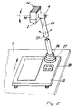
- the 5 has a stand ST which is formed by a tube 25 rotatable about its axis.
- One joint 26 sits, for example, in the base 27 of the stand, a second joint 4 at its upper end.
- the axis of rotation of this second joint 4 is directed horizontally and is perpendicular to that of the other joint 26.
- the axis of the objective 2 of the object camera OK is in turn oriented perpendicular to the axis of rotation of the joint 4 to which it is attached. This means that the object camera OK can be aimed at almost any point in the room.
- the housing 24 of the object camera is essentially cuboid.
- the base 27 of the stand ST can be designed as required so that it is free or that it can be attached to a table surface. In the transportable embodiment shown, it is fastened on a plate-shaped foot 23, on which control elements 28 can also be attached and which also forms the document support.
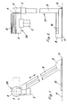
- FIG. 6 to 8 show a further embodiment of an object camera OK with a stand ST which is telescopically adjustable in height and has a pivotable arm 31.
- the arm 31 is fastened at one end to a joint 4 which can be rotated about a horizontal axis and which is seated on two parallel, tubular stator bars 32.
- the uprights 32 each consist of two tubes sliding into each other, which can be locked with the help of clamping screws 35, which each pass through a slot 36 in the outer tube and are screwed into the inner (Fig. 7).
- the length of the slots 36 determines the height of the stand ST.
- the uprights 32 stand on a flat, plate-shaped foot 33, which can be slid on a footprint (table) T under an image display device B, which is indicated by dash-dotted lines, in such a way that the object camera OK is aimed at a user above the screen.
- a second joint 34 is attached, the axis of rotation of which is perpendicular to that of the other joint 4.
- the object camera OK can theoretically be pivoted through 360 °, the axis of the objective 2 moving in a plane perpendicular to the axis of rotation of the joint 34.
- the locking in the desired position is again done using the tensioning screw 37.
- Usual knurled or toggle screws can be used as tensioning screws.
- the object camera OK can be attached to the head of the joint 34 in the same way.
- a second end position is drawn in dash-dot lines, in which the object camera OK is directed downward onto the table T for receiving documents or the like.
- the object camera is both around the joint 4 and also pivoted about the joint 34.
- the movement possibilities are indicated in FIGS. 6 to 8 by directional arrows.
Abstract
Description
Die Erfindung betrifft eine elektronische Objektkamera nach dem Oberbegriff des Anspruchs 1.The invention relates to an electronic object camera according to the preamble of claim 1.
Das deutsche Geschmacksmuster M 89 01 635 zeigt zwei Ausführungen elektronischer Objektkameras für Bildtelefone, bei denen das Gehäuse der Kamera jeweils um eine waagerechte Achse drehbar zwischen zwei parallelen Ständerholmen an deren oberem Ende angebracht ist. Unten enden die Ständerholme an einem Fuß mit Bedien- und Anzeigeelementen für die Kamera. Die elektrischen Leitungen sind von der Kamera oben in die hohlen Ständerholme eingeführt und laufen darin unsichtbar nach unten. Bei der einen Ausführung besteht der Fuß aus einem die Ständerholme verbindenden Gehärnseteil, das an einer Drehscheibe befestigt ist, die z.B. in einem Tisch eingebaut ist. Bei der anderen Ausführung ist der Fuß ein transportables Gehäuse zum Abstellen auf einer Tischfläche. Die Kamera kann um ihre waagerechte Drehachse geschwenkt werden, so daB das Objektiv entweder vertikal auf Dokumente gerichtet werden kann, die unter der Kamera auf dem Tisch liegen, oder horizontal auf eine Person oder auf Gegenstände an einer Wand. Die aufgenommenen Bilder werden mit üblichen Bildfernsprechsystemen zu anderen Teilnehmern übermittelt.The German design M 89 01 635 shows two versions of electronic object cameras for videophones, in which the housing of the camera is attached to its upper end, rotatable about a horizontal axis, between two parallel uprights. At the bottom, the uprights end on a foot with controls and indicators for the camera. The electrical cables are inserted from the camera into the hollow uprights and run invisibly downwards. In one embodiment, the foot consists of a part of the arm connecting the uprights, which is attached to a turntable, e.g. is built into a table. In the other version, the foot is a portable housing that can be placed on a table surface. The camera can be swiveled around its horizontal axis of rotation, so that the lens can either be directed vertically at documents lying on the table under the camera, or horizontally at a person or objects on a wall. The captured images are transmitted to other participants using conventional video telephone systems.
Der Erfindung liegt die Aufgabe zugrunde, die Konstruktion der Objektkamera und ihrer Halterung zu verbessern und damit ihre Handhabung zu vereinfachen. Gelöst wird diese Aufgabe durch die im Anspruch 1 angegebenen Merkmale. Weitere Lösungen sind in den Ansprüchen 5 und 11 angegeben. Vorteilhafte Weiterbildungen sind den Unteransprüchen zu entnehmen. Die vorgeschlagenen Lösungen haben den Vorteil, daß das Einstellen der Kamera mit einer Hand erfolgen kann. Die Ausrichtung ist universell, d.h. die Kamera kann nahezu in alle Richtungen eingestellt werden. Außerdem ist der Platzbedarf auf einem Tisch gering. Mehrere Ausführungen können ohne Demontage weggeräumt werden, wenn dies gewünscht wird, weil der Standfuß nicht festgemacht werden muß. Bei einer Ausführung kann der handelsübliche Lampen-Tragarm (Hebelgetriebe) am Tisch angeklemmt oder angeschraubt werden. Er erlaubt ebenfalls eine freie Höhen- und Positionsbestimmung der Kamera.The invention has for its object to improve the construction of the object camera and its holder and thus to simplify its handling. This object is achieved by the features specified in claim 1. Further solutions are given in
Die Erfindung wird an Ausführungsbeispielen beschrieben, die in den zugehörigen Zeichnungen dargestellt sind. Darin zeigen:
- Fig. 1 bis 3 eine elektronische Objektkamera mit zylindrischem Gehäuse, doppelrohrigem Ständerholm und halbzylindrischem Fuß in Seitenansicht, Vorderansicht und Draufsicht;
- Fig. 4 eine andere Ausführung der Objektkamera mit quaderförmigem Gehäuse und bekanntem Ständer, in perspektivischer Ansicht;
- Fig. 5 eine weitere Ausführung der Objektkamera ähnlich Fig. 4, jedoch mit rohrförmigem Ständer, der auf einer verschiebbaren Platte befestigt ist, in perspektivischer Ansicht;
- Fig. 6 bis 8 eine weitere Ausführung der Objektkamera mit doppelrohrigem Ständer, Schwenkarm und plattenförmigem Fuß zum Unterschieben unter ein Bildwiedergabegerät in Seitenansicht, Rückansicht und Draufsicht.
- Figures 1 to 3, an electronic object camera with a cylindrical housing, double-tube stand and semi-cylindrical base in side view, front view and top view.
- 4 shows another embodiment of the object camera with a cuboid housing and known stand, in a perspective view;
- 5 shows a further embodiment of the object camera similar to FIG. 4, but with a tubular stand which is fastened on a displaceable plate, in a perspective view;
- 6 to 8 a further embodiment of the object camera with a double-tube stand, swivel arm and plate-shaped base for being pushed under an image display device in side view, rear view and top view.
Die Fig. 1 bis 3 zeigen in verschiedenen Ansichten eine elektronische Objektkamera OK, wie sie als Zusatzgerät z.B. für Bildfernsprecher zum Einsatz kommt, um Dokumente, Gegenstände und Personen aufnehmen und übermitteln zu können. Die Kamera, von der nur das Objektiv 2 sichtbar ist, ist in einem zylindrischen Gehäuse 3 untergebracht, das auf der dem Objektiv abgewandten Hälfte der Mantelfläche mit einer achsparallelen Riffelung 13 versehen ist, welche die Handhabung erleichtert. An der einen Stirnseite ist das Gehäuse 3 mit einem Gelenk 4 verbunden, so daß das Gehäuse um seine Achse gedreht werden kann. Dieses Gelenk 4 ist wiederum mit einem weiteren Gelenk 5, dessen Drehachse vertikal gerichtet ist, in einem Gelenkkopf 6 zusammengefaßt. Dadurch kann die Objektkamera OK praktisch in jede Richtung gedreht werden. Die Bewegungsmöglichkeiten sind durch Pfeile angedeutet. Dargestellt ist ihre Ausrichtung in der Vertikalen, um z.B. ein auf dem Tisch T liegendes Papier aufzunehmen. Weitere Stellungen sind in Fig. 1 und Fig. 3 durch strichpunktierte Linien angedeutet. In den Gelenken 4 und 5 können Rastmittel vorgesehen werden, die das Einstellen bestimmter, häufig wiederkehrender Kamerastellungen erleichtern. Ebenso können durch nicht dargestellte Anschläge die Drehwinkel in den Gelenken 4 und 5 begrenzt werden, was im Hinblick auf die elektrischen Leitungen zweckmäßig ist, um deren Verdrillen in Grenzen zu halten.1 to 3 show in different views an electronic object camera OK, as used as an additional device e.g. for video telephones is used to record and transmit documents, objects and people. The camera, of which only the
Der Gelenkkopf 6 sitzt auf einem Ständer ST, der aus einem Fuß 8 und einem Ständerholm 9, der den Gelenkkopf mit dem Fuß verbindet, besteht. Der Fuß 8 ist ein liegender Halbzylinder, in dem Bedienelemente 10 untergebracht sind. Die ebene Standfläche ist mit Gummifüßen 11 versehen. Der Ständerholm 9 ist geneigt, er schließt mit der Horizontalen einen Winkel von ungefähr 60° ein. Er wird von zwei parallelen Rohren gebildet, die seitlich am Fuß 8 enden, so daß dieser auf der gleichen Seite des Ständers ST liegt wie die Objektkamera OK. Der Ständerholm 9 kann teleskopartig verkürzt bzw. verlängert werden. Der Fuß 8 ist so schwer, daß die Objektkamera trotz des geneigten Ständerholmes 9 fest steht. Bei Bedarf kann der Fuß 8 mit einer Klemmvorrichtung zum Befestigen an einer Tischkante ausgerüstet werden (nicht dargestellt). An der einen Stirnseite des Fußes 8, zweckmäßig auf der gleichen Seite, auf der der Ständerholm 9 liegt, ist ein Anlegelineal 12 für Dokumente befestigt, das senkrecht zur Achse des Halbzylinders verläuft. Es ist als Stab ausgeführt und erleichtert das richtige Auflegen eines bestimmten Papierformates unter der Objektkamera OK.The
In Fig. 4 ist eine andere Ausführung der Objektkamera OK abgebildet. Das Gehäuse 15 hat annähernd quaderförmige Gestalt, aus dem auf einer Breitseite ein etwa zylindrischer Ansatz 16 vorspringt, in dem das Objektiv angeordnet ist. Die Stirnseite dieses Ansatzes 16 enthält rund um das Objektiv 2 eine Lagerung als Gelenk 17, dessen Drehachse parallel zur Objektivachse verläuft oder mit ihr zusammenfällt. Von diesem Gelenk 17 führt ein Arm 18 zum Kopf des Ständers ST. Der Arm ist geteilt und enthält ein Gelenk 4, dessen Achse quer zu der des Gelenkes 17, also waagerecht verläuft. Von dem Ständer ST ist nur das obere Ende angedeutet, weil es sich um ein an sich bekanntes Hebelgetriebe handelt, wie es für Lampen üblich ist, die z.B. an einem Tisch befestigt werden können. Solche Hebelgetriebe sind als Parallelogramm-Tragarme derart ausgebildet, daß beim Bewegen ein an seinem Kopf angebrachter Gegenstand nur seinen Abstand, aber nicht seine waagerechte Stellung bezüglich der Unterlage (Tisch), an der das Hebelgetriebe befestigt ist, verändert.Another embodiment of the object camera OK is shown in FIG. 4. The
Somit kann die Objektkamera sowohl in der Höhe verfahren als auch um zwei Raumachsen gedreht werden. Rastvorrichtungen in den Gelenken erleichtern wiederum das Einstellen bestimmter Stellungen wie bei der zuvor geschilderten Ausführung.This means that the object camera can be moved vertically and rotated around two spatial axes. Locking devices in the joints in turn facilitate the setting of certain positions as in the previously described embodiment.
Am Objektiv 2 ist ein Stellhebel 19 befestigt, der über die Lagerung bzw. das Gelenk 17 herausragt und eine bequeme Einstellung der Entfernung am Objektiv ermöglicht. Die elektrischen Leitungen L der Objektkamera sind am Kopf des Ständers ST in die Holme 20 eingeführt. Über den Griffbereich auf dem Gehäuse 15 der Objektkamera ist ein Benutzer in der Lage, diese mit einer Hand in einer Bewegung in jede gewünschte Stellung zu bringen. Das unmittelbar darunter angeordnete Handhabungsfeld ermöglicht gleichzeitig auch alle kameraspezifischen Einstellungen wie Schärfe und Weißabgleich.On the
Die Ausführung nach Fig. 5 hat einen Ständer ST, der von einem um seine Achse drehbaren Rohr 25 gebildet wird. Das eine Gelenk 26 sitzt beispielsweise im Sockel 27 des Ständers, ein zweites Gelenk 4 an seinem oberen Ende. Die Drehachse dieses zweiten Gelenkes 4 ist horizontal gerichtet und steht senkrecht auf der des anderen Gelenkes 26. Die Achse des Objektivs 2 der Objektkamera OK ist wiederum senkrecht zu der Drehachse des Gelenkes 4 ausgerichtet, an dem sie befestigt ist. Damit läßt sich die Objektkamera OK nahezu auf jeden Punkt des Raumes richten. Das Gehäuse 24 der Objektkamera ist im wesentlichen quaderförmig ausgebildet.5 has a stand ST which is formed by a
Der Sockel 27 des Ständers ST kann je nach Bedarf so ausgebildet sein, daß er frei steht oder daß er auf einer Tischfläche befestigt werden kann. Bei der dargestellten transportablen Ausführung ist er auf einem plattenförmigen Fuß 23 befestigt, auf dem außerdem Bedienelemente 28 angebracht werden können und der zugleich die Dokumenten-Auflage bildet.The
Die Fig. 6 bis 8 zeigen eine weitere Ausführung einer Objektkamera OK mit einem Ständer ST, der teleskopartig in der Höhe verstellbar ist und einen schwenkbaren Arm 31 hat. Der Arm 31 ist mit dem einen Ende an einem um eine waagerechte Achse drehbaren Gelenk 4 befestigt, das auf zwei parallelen, rohrförmigen Ständerholmen 32 sitzt. Die Ständerholme 32 bestehen jeweils aus zwei ineinander gleitenden Rohren, die mit Hilfe von Spannschrauben 35 feststellbar sind, welche jeweils einen Schlitz 36 im äußeren Rohr durchsetzen und in das innere geschraubt sind (Fig. 7). Die Länge der Schlitze 36 bestimmt die Stellhöhe des Ständers ST. Beim Festdrehen der Spannschrauben 35 werden die inneren gegen die äußeren Rohre verspannt und festgelegt. Die Ständerholme 32 stehen auf einem flachen, plattenförmigen Fuß 33, der auf einer Stellfläche (Tisch) T so unter ein Bildwiedergabegerät B, das strichpunktiert angedeutet ist, geschoben werden kann, daß die Objektkamera OK über dem Bildschirm auf einen Benutzer gerichtet ist.6 to 8 show a further embodiment of an object camera OK with a stand ST which is telescopically adjustable in height and has a
Am freien Ende des Armes 31 ist ein zweites Gelenk 34 angebracht, dessen Drehachse zu der des anderen Gelenkes 4 senkrecht steht. Dadurch kann die Objektkamera OK theoretisch um 360° geschwenkt werden wobei sich die Achse des Objektivs 2 in einer Ebene senkrecht zur Drehachse des Gelenkes 34 bewegt. Das Feststellen in der gewünschten Stellung geschieht wieder mittels Spannschraube 37. Als Spannschrauben können übliche Rändel- oder Knebelschrauben verwendet werden. Die Befestigung der Objektkamera OK am Kopf des Gelenkes 34 kann in der gleichen Weise erfolgen.At the free end of the
In Fig. 6 ist strichpunktiert eine zweite Endstellung eingezeichnet, in der die Objektkamera OK nach unten auf den Tisch T zur Aufnahme von Dokumenten oder dergleichen gerichtet ist. Die Objektkamera wird dabei sowohl um das Gelenk 4 als auch um das Gelenk 34 geschwenkt. Die Bewegungsmöglichkeiten sind in den Fig. 6 bis 8 durch Richtungspfeile angedeutet.6, a second end position is drawn in dash-dot lines, in which the object camera OK is directed downward onto the table T for receiving documents or the like. The object camera is both around the
Claims (16)
Applications Claiming Priority (2)
| Application Number | Priority Date | Filing Date | Title |
|---|---|---|---|
| DE9013986U DE9013986U1 (en) | 1990-10-08 | 1990-10-08 | |
| DE9013986U | 1990-10-08 |
Publications (3)
| Publication Number | Publication Date |
|---|---|
| EP0480232A2 true EP0480232A2 (en) | 1992-04-15 |
| EP0480232A3 EP0480232A3 (en) | 1993-10-27 |
| EP0480232B1 EP0480232B1 (en) | 1996-01-17 |
Family
ID=6858171
Family Applications (1)
| Application Number | Title | Priority Date | Filing Date |
|---|---|---|---|
| EP91116203A Expired - Lifetime EP0480232B1 (en) | 1990-10-08 | 1991-09-24 | Electronic camera |
Country Status (2)
| Country | Link |
|---|---|
| EP (1) | EP0480232B1 (en) |
| DE (2) | DE9013986U1 (en) |
Cited By (5)
| Publication number | Priority date | Publication date | Assignee | Title |
|---|---|---|---|---|
| EP0524474A2 (en) * | 1991-07-26 | 1993-01-27 | Alcatel SEL Aktiengesellschaft | Picturephone |
| EP0560028A1 (en) * | 1992-03-05 | 1993-09-15 | Usm U. Schaerer Soehne Ag | Videophone conference table for a conference participant |
| EP0749037A2 (en) * | 1995-06-14 | 1996-12-18 | Canon Kabushiki Kaisha | Image input apparatus with means for varying and indicating the orientation of a camera head |
| WO2003076843A1 (en) * | 2002-03-08 | 2003-09-18 | Wolfvision Gmbh | Articulated arm especially for a device for optically capturing objects |
| US7091961B2 (en) | 1993-06-29 | 2006-08-15 | Ditzik Richard J | Desktop device with adjustable flat screen display |
Families Citing this family (3)
| Publication number | Priority date | Publication date | Assignee | Title |
|---|---|---|---|---|
| DE9013986U1 (en) * | 1990-10-08 | 1990-12-13 | Standard Elektrik Lorenz Ag, 7000 Stuttgart, De | |
| DE9205664U1 (en) * | 1992-04-27 | 1992-07-23 | Standard Elektrik Lorenz Ag, 7000 Stuttgart, De | |
| FR2725805B1 (en) * | 1994-10-18 | 1996-12-20 | Alcatel Business Systems | APPARATUS WITH SCREEN AND CAMERA HAVING A LENS ORIENTATION MECHANISM |
Citations (6)
| Publication number | Priority date | Publication date | Assignee | Title |
|---|---|---|---|---|
| US3089028A (en) * | 1961-03-23 | 1963-05-07 | Golda G Klampferer | Stand with adjustably mounted head |
| FR2382140A1 (en) * | 1977-02-25 | 1978-09-22 | Lartigue Alain | Mobile articulated TV camera boom - has cradle in gimbals with camera mounting plate to give wide range of movement |
| US4258387A (en) * | 1979-10-17 | 1981-03-24 | Lemelson Jerome H | Video telephone |
| DE8902287U1 (en) * | 1989-02-27 | 1989-04-20 | Telenorma Telefonbau Und Normalzeit Gmbh, 6000 Frankfurt, De | |
| DE9013986U1 (en) * | 1990-10-08 | 1990-12-13 | Standard Elektrik Lorenz Ag, 7000 Stuttgart, De | |
| DE9110664U1 (en) * | 1991-08-29 | 1991-11-14 | Standard Elektrik Lorenz Ag, 7000 Stuttgart, De |
-
1990
- 1990-10-08 DE DE9013986U patent/DE9013986U1/de not_active Expired - Lifetime
-
1991
- 1991-09-24 DE DE59107280T patent/DE59107280D1/en not_active Expired - Fee Related
- 1991-09-24 EP EP91116203A patent/EP0480232B1/en not_active Expired - Lifetime
Patent Citations (6)
| Publication number | Priority date | Publication date | Assignee | Title |
|---|---|---|---|---|
| US3089028A (en) * | 1961-03-23 | 1963-05-07 | Golda G Klampferer | Stand with adjustably mounted head |
| FR2382140A1 (en) * | 1977-02-25 | 1978-09-22 | Lartigue Alain | Mobile articulated TV camera boom - has cradle in gimbals with camera mounting plate to give wide range of movement |
| US4258387A (en) * | 1979-10-17 | 1981-03-24 | Lemelson Jerome H | Video telephone |
| DE8902287U1 (en) * | 1989-02-27 | 1989-04-20 | Telenorma Telefonbau Und Normalzeit Gmbh, 6000 Frankfurt, De | |
| DE9013986U1 (en) * | 1990-10-08 | 1990-12-13 | Standard Elektrik Lorenz Ag, 7000 Stuttgart, De | |
| DE9110664U1 (en) * | 1991-08-29 | 1991-11-14 | Standard Elektrik Lorenz Ag, 7000 Stuttgart, De |
Cited By (10)
| Publication number | Priority date | Publication date | Assignee | Title |
|---|---|---|---|---|
| EP0524474A2 (en) * | 1991-07-26 | 1993-01-27 | Alcatel SEL Aktiengesellschaft | Picturephone |
| EP0524474A3 (en) * | 1991-07-26 | 1993-03-17 | Alcatel Sel Aktiengesellschaft | Picturephone |
| EP0560028A1 (en) * | 1992-03-05 | 1993-09-15 | Usm U. Schaerer Soehne Ag | Videophone conference table for a conference participant |
| US7091961B2 (en) | 1993-06-29 | 2006-08-15 | Ditzik Richard J | Desktop device with adjustable flat screen display |
| EP0749037A2 (en) * | 1995-06-14 | 1996-12-18 | Canon Kabushiki Kaisha | Image input apparatus with means for varying and indicating the orientation of a camera head |
| EP0749037A3 (en) * | 1995-06-14 | 1999-06-23 | Canon Kabushiki Kaisha | Image input apparatus with means for varying and indicating the orientation of a camera head |
| US6115068A (en) * | 1995-06-14 | 2000-09-05 | Canon Kabushiki Kaisha | Positionable image input apparatus |
| WO2003076843A1 (en) * | 2002-03-08 | 2003-09-18 | Wolfvision Gmbh | Articulated arm especially for a device for optically capturing objects |
| US7104512B2 (en) | 2002-03-08 | 2006-09-12 | Wolfvision Gmbh | Articulated arm especially for a device for optically capturing objects |
| CN100417859C (en) * | 2002-03-08 | 2008-09-10 | 沃福视讯股份有限公司 | Articulated arm especially for a device for optically capturing objects |
Also Published As
| Publication number | Publication date |
|---|---|
| DE9013986U1 (en) | 1990-12-13 |
| EP0480232B1 (en) | 1996-01-17 |
| DE59107280D1 (en) | 1996-02-29 |
| EP0480232A3 (en) | 1993-10-27 |
Similar Documents
| Publication | Publication Date | Title |
|---|---|---|
| DE10044213C2 (en) | Device for hanging projectors | |
| EP0230236B1 (en) | Apparatus for positioning data display units | |
| EP0480232B1 (en) | Electronic camera | |
| DE10145197B4 (en) | Decoupled weight compensation for a camera balance device | |
| DE10208413A1 (en) | Rotatable tripod stand for camera constructed from kit elements allowing stand to be used for cameras of different weights and sizes rotatable about one, two or more axes | |
| DE3222954C2 (en) | Light barrier unit | |
| EP1409916A1 (en) | Balance system with roll handle for hand-held cameras | |
| DE10145198C1 (en) | Gimbal hanger for a camera balance device | |
| DE4024585C2 (en) | Ball joint head for photographic tripods | |
| DE10145199B4 (en) | Cardanic suspension device for a camera balance device | |
| EP0019243B1 (en) | Stand for projection screens | |
| EP0568857A1 (en) | Electronic camera | |
| DE4423586C2 (en) | Monopod tripod | |
| DE202014101905U1 (en) | tripod head | |
| DE890421C (en) | Extension device for tripods or ball joints | |
| DE202007005393U1 (en) | Shoulder stand for a TV or film camera | |
| DE1541163A1 (en) | Arrangement for x-ray fluoroscopy | |
| DE102014206209B4 (en) | camera crane | |
| AT405123B (en) | Easel | |
| DE2128825A1 (en) | tripod | |
| DE2838403C3 (en) | Cinema tilt head for a cinema camera with equipment rack | |
| EP0213078A2 (en) | Compartment camera | |
| CH545981A (en) | ||
| DE7423041U (en) | Device for setting up devices, in particular projection apparatus | |
| DE2034098A1 (en) | tripod |
Legal Events
| Date | Code | Title | Description |
|---|---|---|---|
| PUAI | Public reference made under article 153(3) epc to a published international application that has entered the european phase |
Free format text: ORIGINAL CODE: 0009012 |
|
| AK | Designated contracting states |
Kind code of ref document: A2 Designated state(s): CH DE FR IT LI |
|
| RAP3 | Party data changed (applicant data changed or rights of an application transferred) |
Owner name: ALCATEL SEL AKTIENGESELLSCHAFT |
|
| PUAL | Search report despatched |
Free format text: ORIGINAL CODE: 0009013 |
|
| AK | Designated contracting states |
Kind code of ref document: A3 Designated state(s): CH DE FR IT LI |
|
| 17P | Request for examination filed |
Effective date: 19931217 |
|
| 17Q | First examination report despatched |
Effective date: 19940722 |
|
| GRAA | (expected) grant |
Free format text: ORIGINAL CODE: 0009210 |
|
| AK | Designated contracting states |
Kind code of ref document: B1 Designated state(s): CH DE FR IT LI |
|
| REF | Corresponds to: |
Ref document number: 59107280 Country of ref document: DE Date of ref document: 19960229 |
|
| ITF | It: translation for a ep patent filed |
Owner name: DOTT. ANTONIO SERGI |
|
| ET | Fr: translation filed | ||
| PLBE | No opposition filed within time limit |
Free format text: ORIGINAL CODE: 0009261 |
|
| STAA | Information on the status of an ep patent application or granted ep patent |
Free format text: STATUS: NO OPPOSITION FILED WITHIN TIME LIMIT |
|
| 26N | No opposition filed | ||
| PGFP | Annual fee paid to national office [announced via postgrant information from national office to epo] |
Ref country code: CH Payment date: 19990816 Year of fee payment: 9 |
|
| PGFP | Annual fee paid to national office [announced via postgrant information from national office to epo] |
Ref country code: FR Payment date: 19990817 Year of fee payment: 9 |
|
| PGFP | Annual fee paid to national office [announced via postgrant information from national office to epo] |
Ref country code: DE Payment date: 19990820 Year of fee payment: 9 |
|
| PG25 | Lapsed in a contracting state [announced via postgrant information from national office to epo] |
Ref country code: LI Free format text: LAPSE BECAUSE OF NON-PAYMENT OF DUE FEES Effective date: 20000930 Ref country code: CH Free format text: LAPSE BECAUSE OF NON-PAYMENT OF DUE FEES Effective date: 20000930 |
|
| PG25 | Lapsed in a contracting state [announced via postgrant information from national office to epo] |
Ref country code: FR Free format text: LAPSE BECAUSE OF NON-PAYMENT OF DUE FEES Effective date: 20010531 |
|
| PG25 | Lapsed in a contracting state [announced via postgrant information from national office to epo] |
Ref country code: DE Free format text: LAPSE BECAUSE OF NON-PAYMENT OF DUE FEES Effective date: 20010601 |
|
| REG | Reference to a national code |
Ref country code: FR Ref legal event code: ST |
|
| PG25 | Lapsed in a contracting state [announced via postgrant information from national office to epo] |
Ref country code: IT Free format text: LAPSE BECAUSE OF NON-PAYMENT OF DUE FEES Effective date: 20050924 |
|
| REG | Reference to a national code |
Ref country code: CH Ref legal event code: PL Ref country code: CH Ref legal event code: NV Representative=s name: JUERG ULRICH C/O ALCATEL STR AG Ref country code: CH Ref legal event code: EP |