EP0479432B1 - Method and apparatus for dynamic channel bandwidth allocation among multiple parallel video coders - Google Patents
Method and apparatus for dynamic channel bandwidth allocation among multiple parallel video coders Download PDFInfo
- Publication number
- EP0479432B1 EP0479432B1 EP91308073A EP91308073A EP0479432B1 EP 0479432 B1 EP0479432 B1 EP 0479432B1 EP 91308073 A EP91308073 A EP 91308073A EP 91308073 A EP91308073 A EP 91308073A EP 0479432 B1 EP0479432 B1 EP 0479432B1
- Authority
- EP
- European Patent Office
- Prior art keywords
- channel sharing
- video
- factors
- frame
- estimated channel
- Prior art date
- Legal status (The legal status is an assumption and is not a legal conclusion. Google has not performed a legal analysis and makes no representation as to the accuracy of the status listed.)
- Expired - Lifetime
Links
Images


Classifications
-
- H—ELECTRICITY
- H04—ELECTRIC COMMUNICATION TECHNIQUE
- H04N—PICTORIAL COMMUNICATION, e.g. TELEVISION
- H04N7/00—Television systems
- H04N7/12—Systems in which the television signal is transmitted via one channel or a plurality of parallel channels, the bandwidth of each channel being less than the bandwidth of the television signal
-
- H—ELECTRICITY
- H04—ELECTRIC COMMUNICATION TECHNIQUE
- H04N—PICTORIAL COMMUNICATION, e.g. TELEVISION
- H04N19/00—Methods or arrangements for coding, decoding, compressing or decompressing digital video signals
- H04N19/60—Methods or arrangements for coding, decoding, compressing or decompressing digital video signals using transform coding
- H04N19/61—Methods or arrangements for coding, decoding, compressing or decompressing digital video signals using transform coding in combination with predictive coding
-
- H—ELECTRICITY
- H04—ELECTRIC COMMUNICATION TECHNIQUE
- H04N—PICTORIAL COMMUNICATION, e.g. TELEVISION
- H04N19/00—Methods or arrangements for coding, decoding, compressing or decompressing digital video signals
- H04N19/60—Methods or arrangements for coding, decoding, compressing or decompressing digital video signals using transform coding
- H04N19/63—Methods or arrangements for coding, decoding, compressing or decompressing digital video signals using transform coding using sub-band based transform, e.g. wavelets
-
- H—ELECTRICITY
- H04—ELECTRIC COMMUNICATION TECHNIQUE
- H04N—PICTORIAL COMMUNICATION, e.g. TELEVISION
- H04N19/00—Methods or arrangements for coding, decoding, compressing or decompressing digital video signals
- H04N19/10—Methods or arrangements for coding, decoding, compressing or decompressing digital video signals using adaptive coding
- H04N19/102—Methods or arrangements for coding, decoding, compressing or decompressing digital video signals using adaptive coding characterised by the element, parameter or selection affected or controlled by the adaptive coding
- H04N19/115—Selection of the code volume for a coding unit prior to coding
-
- H—ELECTRICITY
- H04—ELECTRIC COMMUNICATION TECHNIQUE
- H04N—PICTORIAL COMMUNICATION, e.g. TELEVISION
- H04N19/00—Methods or arrangements for coding, decoding, compressing or decompressing digital video signals
- H04N19/10—Methods or arrangements for coding, decoding, compressing or decompressing digital video signals using adaptive coding
- H04N19/134—Methods or arrangements for coding, decoding, compressing or decompressing digital video signals using adaptive coding characterised by the element, parameter or criterion affecting or controlling the adaptive coding
- H04N19/146—Data rate or code amount at the encoder output
-
- H—ELECTRICITY
- H04—ELECTRIC COMMUNICATION TECHNIQUE
- H04N—PICTORIAL COMMUNICATION, e.g. TELEVISION
- H04N19/00—Methods or arrangements for coding, decoding, compressing or decompressing digital video signals
- H04N19/30—Methods or arrangements for coding, decoding, compressing or decompressing digital video signals using hierarchical techniques, e.g. scalability
Definitions
- This invention relates to apparatus and methods for dynamically allocating portions of available overall channel bandwidth in a video image coding system.
- High definition television promises to offer a wider viewing area and improved image quality when compared with today's television.
- an uncompressed digital HDTV channel may require transmission bandwidth up to one gigabit per second. It is therefore desirable to compress the HDTV signal in a manner such that image quality is not significantly reduced and yet the HDTV signal can be transmitted at lower speeds.
- One of the main difficulties in compressing HDTV signals is the relatively high computation speeds required of the digital circuitry performing the encoding processes that achieve the compression. This difficulty is exacerbated when state-of-the-art compression algorithms are employed since these algorithms obtain increased compression only through increased complexity of calculation.
- the increased complexity of calculation requires that more computation be performed in the available time thereby requiring each processing unit to operate faster.
- the requirement of performing complex computations at high speeds can significantly increase the cost of an HDTV coder.
- One possible solution is to divide the HDTV image into sub-images and to process all the sub-images in parallel. Such a solution seeks to utilize slower and therefore cheaper processing circuits to accomplish the desired compression.
- a single encoder performs the entire compression algorithm for an individual sub-image. Only input of that portion of the original HDTV signal representing the sub-image and output of the encoded signals representing the sub-image after compression need be performed at a high speed. This input and output activity is bursty in nature since it occurs only for a short period of time relative to the transmission time of the entire uncompressed image. Actual processing of the pels contained within each sub-image by an encoder can take place at a much slower rate between the bursts of image signal input and output.
- each sub-image may vary considerably. It is desirable to allocate more bandwidth to those sub-images that are more complex since the effectiveness of compression algorithms decreases as image complexity increases.
- a problem with an arrangement as described above is how to specify a bit rate for each encoder so as to allocate the available bandwidth most efficiently. Predetermined bit rate assignment is inefficient because it is unable to adjust for differences in image complexity and may thereby result in variations in the quality of different areas of the image that is reconstructed from the compressed signal. Viewers' perceptions of such variations in the quality of the reconstructed image are negative.
- Prior attempts to dynamically allocate the available bandwidth among the various video coders required knowledge by an allocation unit of the variance of each individual sub-image. Extensive computing capacity at high speeds is required to compute the variance of a sub-image in the limited time available because the variance is a complex calculation. This requirement of high speed calculations causes dynamic allocation units that compute variances to be expensive.
- FIG. 1 is an exemplary system overview, in simplified block diagram format, of a video encoder embodying the invention.
- the system is comprised of video splitter 101, multiple parallel video coders 102-1 through 102-N, dynamic channel allocation unit 103 and multiplexer 104.
- Video splitter 101 is supplied with original video signal VIDEO IN 105.
- Signal VIDEO IN 105 is a bit steam that comprises a series of frames each containing an image.
- signal VIDEO IN 105 would be supplied by a well known and commercially available video signal source including, without limitation: a video camera, a videocassette recorder, or a videodisc player unit.
- the bandwidth of signal VIDEO IN 105 is wide. For example, the bandwidth of a video signal supplied by a video camera encoding images in the Zenith proposed HDTV format is approximately 37 Mhz.
- Video splitter 101 splits each successive image of signal VIDEO IN 105 into N sub-images, each sub-image comprised of one of signals SUB-VIDEO 106-1 through SUB-VIDEO 106-N.
- the splitting can be achieved by employing a spatial decomposition or, alternatively, by employing a sub-band frequency decomposition.
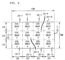
- An exemplary spacial decomposition of an image is shown in FIG. 2.
- Each resulting sub-image comprises 240 lines.
- Sub-images 201-1 through 201-9 have 352 pels per line and sub-images 202-10 through 202-12 have 224 pels per line.
- the spacial decomposition shown was selected for implementation convenience so that the resulting sub-images would be compatible in size with the Common Intermediate Format (CIF) defined in the CCITT recommendation H.261 (Px64kbps standard). This selection should not be construed as placing any limitation on the invention.
- CIF Common Intermediate Format
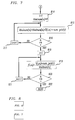
- FIG. 3 shows exemplary apparatus contained in video splitter 105 (FIG. 1) for performing an exemplary frequency decomposition of an image contained within an HDTV frame supplied from signal VIDEO IN 105.
- the decomposition is accomplished in an exemplary manner by employing a successive series of alternating two stage filter banks, horizontal filter banks 301-1 through 301-5 and vertical filter banks 302-1 through 302-10, and sub-samplers 303-1 through 303-30 to progressively decompose each resulting filtered and sub-sampled video signal until a desired sub-image size and frequency distribution is obtained.
- Each horizontal filter bank 301 effects a separation in the horizontal direction of the high and low frequency components of the image contained within the video signal with which it is supplied.
- each vertical filter bank 302 effects a separation in the vertical direction of the high and low frequency components of the image contained within the video signal with which it is supplied.
- horizontal filter banks 301 vertical filter banks 302 and sub-samplers 303 are not shown. However, the various interconnections required will be clear to one skilled in the art.
- Each of horizontal filter banks 301 is comprised of horizontal low pass filter (Hlp) 304 and horizontal high pass filter (Hhp) 305.
- Each of vertical filter banks 302 is comprised of vertical low pass filter (Vlp) 306 and vertical high pass filter (Vhp) 307.
- each resulting video signals are sub-sampled by 2.
- the sub-sampling is performed by sub-samplers 303.
- each resulting 1/16th size sub-image (180 lines by 320 pels) is suitable to be processed by a video coder corresponding to the Px64kbps standard.
- each of signals SUB-VIDEO 106 supplied as output corresponds to a video signal comprising one of the 16 sub-images. It is noted that the instant invention can be applied to any video image and no limitation should be construed by the use of HDTV as an exemplary system in which to practice the invention.
- Each of signals SUB-VIDEO 106-1 (FIG. 1) through 106-N is supplied to a corresponding one of video coders 102-1 through 102-N.
- Video coders 102 encode their respective ones of signals SUB-VIDEO 106 and supply as an output one of DATA STREAMS 110-1 through 110-N.
- Each of DATA STREAMS 110 represents the sub-image contained in the corresponding one of SUB-VIDEO 106 in an encoded format. Methods of performing such encoding, e.g., conditional replenishment, motion compensated predictive coding and the Px64kbps standard, are well know.
- DATA STREAMS 110 Also encoded into DATA STREAMS 110 is any additional control information required to reconstruct, to the accuracy inherent in the coding technique employed, each of signals SUB-VIDEO 106.
- the number of bits desired to be supplied as an output by each of video coders 102 can be specified by control signals supplied to video coders 102.
- the quantization step size employed by the coder is then determined based on the number of bits desired and the complexity of the sub-image being encoded.
- the set comprised of the average number of bits per pel produced by each of video coders 102 in frame n-1, where n is a variable indicating the current frame, is b(i,n-1) for i 1,...N,.
- One member of this set is supplied to dynamic channel allocation unit 103 from each of video coders 102 over signal leads 107-1 through 107-N.
- Each individual channel sharing factor, f(i,n) is an indication of the fraction of the overall channel bandwidth, C, allocated to video coder 102-i for supplying to the channel the contents of its sub-image for frame n.
- Channel allocation unit 103 supplies the channel sharing factors f(i,n) to each of video coders 102 over signal leads 109-1 through 109-N.
- the channel sharing factors may be in any of several formats including but not limited to: a specification of the exact number of bits each video coder 102 is to produce for the current frame; a fractional number indicating the percentage of time allocated to each coder for transmission of the bits it produces for the current frame; or a quantizer step size, either average or fixed, to be employed.
- DATA STREAMS 110 are supplied to multiplexer 104. Also, the information contained in the channel sharing factors are supplied to multiplexer 104 over signal CONTROL 111. Multiplexer 104 combines each of DATA STREAMS 110 into a single signal, COMPRESSED DATA OUT 112 that is supplied as output Also incorporated into signal COMPRESSED DATA OUT 112 is formatting information indicating how to recover each of DATA STREAMS 110. Methods of multiplexing multiple data streams are well known.
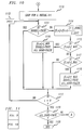
- dynamic channel allocation unit 103 comprises initial sharing factor estimator 401, optional estimate modification unit 402 and optional sharing factor normalization unit 403.
- FIG. 5 Shown in FIG. 5, in simplified block diagram format, is exemplary implementation of initial sharing factor estimator 401 (FIG. 4).
- q(i,n-1) is supplied from each of video coders 102 (FIG. 1) as input to image characteristic parameter computation unit 501 and quantization step size estimator unit 502 while b(i,n-1) is also supplied as input to image characteristic parameter computation unit 501.
- F(i,n-1) is supplied to the number of bits for each coder estimator 503.
- Quantization step size estimator 502 supplies a set ot initial estimates of the desired quantization step size to be used for all video coders 102 for processing current frame n, q ⁇ (n).
- Sharing factors computation unit 504 receives as input the set of initial estimates of the desired average bits per pel b ⁇ (i,n), and supplies as an output a set of an initial set of estimated channel sharing factors, f(i,n), one for each of the N video coders 102.
- the routine is entered via step 801 after the processing of the previous frame by each of video coders 102 (FIG. 1) and their supplying of b(i,n-1) and q(i,n-1) to dynamic channel allocation unit 103 but prior their to processing of the current frame.
- the routine is not entered. This is because there was no previous frame and therefore no values are available for b(i,n-1) and q(i,n-1).
- the value of index i is initialized to 1 in step 802.
- F(i,n-1) is an image characteristic parameter for video coder 102-i that is determined in frame n-1 and ⁇ is a coder dependent parameter that is often a constant number, e.g. 1.39.
- conditional branch point 804 tests if i is equal to N, i.e., has a value been computed for each video coder. If the test result in step 804 is NO, control is passed to step 805 which increments the value of i. Control is then passed back to step 803.
- steps 802 through 805 would be performed by image characteristic parameter computation unit 501 (FIG. 5).
- conditional branch point 808 tests if i is equal to N. If the test result in step 808 is NO, control is passed to step 809 which increments the value of i. Control is then passed back to step 807.
- steps 806 through 809 are performed by quantization step size estimator 502 (FIG. 5)
- step 810 If the test result in step 808 is YES, control is passed to step 810 which resets the value of i to 1. Thereafter, in step 811, an estimate of the average number of bits per pixel for each coder to be employed for current frame n in which q ⁇ (n) is used as the quantization step size, is computed according to Next, conditional branch point 812 tests if i is equal to N. If the test result in step 812 is NO, control is passed to step 813 which increments the value of i. Control is then passed back to step 811. Steps 810 through 813 would typically be executed by number of bits for each coder estimator 503 (FIG. 5).
- step 812 If the test result in step 812 is YES, control is passed to a loop comprising steps 814 through 817 which calculates and stores in a temporary summing variable bhatsum(n) a total of the estimated number of bits in frame n.
- the number of bits estimated to be used for each sub-image is derived by obtaining the product of the average number of bits per pel estimated for video coder 102-i, b ⁇ (i,n), and the number of pels in each sub-image num_pels(i).
- Step 814 resets the value of i to 1 and sets the value of bhatsum(n) to zero (0).
- step 815 the value of current value of b ⁇ (i,n) is multiplied by the number of pels in signal SUB-VIDEO 106-i, num_pels(i), and added to the current value of bhatsum(n) to produce an new value of bhatsum(n).
- conditional branch point 816 tests if i is equal to N. If the test result in step 816 is NO, control is passed to step 817 which increments the value of i. Control is then passed back to step 815.
- step 816 If the test result in step 816 is YES, control is passed to step 818 which resets the value of-i to 1.
- Conditional branch point 820 then tests if i is equal to N. If the test result in step 820 is NO, control is passed to step 821 which increments the value of i. Control is then passed back to step 819. If the test result in step 820 is YES, the routine is exited via step 822.
- the estimated channel sharing factors are available to be supplied as output f(i,n) from initial sharing factor estimator 401. Steps 814 through 822 would typically be performed by sharing factors computation unit 504 (FIG. 5)
- Optional estimate modification unit 402 receives as input the estimated channel sharing factors from initial sharing estimator 401.
- Optional estimate modification unit 402 modifies the estimated channel sharing factors to reflect the prior history of the complexity of each sub-image, in accordance with an aspect of the invention.
- An exemplary way to incorporate the prior history of each sub-image is to use a weighted average of the actually employed channel sharing factors for the prior k frames and the estimated channel sharing factor for the current frame.
- the modified estimated channel sharing factors f(i,n) are supplied as output f(i,n) by estimate modification unit 402.
- An advantage of employing optional estimate modification unit 402 is that a smoother change of the channel sharing factors can be achieved as compared to when initial sharing estimator 401 is employed alone.
- channel sharing factors f(i,n) supplied by initial sharing estimator 401 or optional estimate modification unit 402 may be employed directly, it may be desirable to normalize the channel sharing factors by employing optional sharing factor normalization unit 403. This is desirable because video coders 102 (FIG. 1) may not work at rates higher than a certain limit. Therefore, an upper limit on each channel sharing factor, f_MAX is employed. Further, image dependent parameter F(i,n-1) may have a sudden change during a scene change. To insure the provision of a minimum channel bandwidth for each of video coders 102, a lower limit on each channel sharing factor, f_MIN is employed to help reduce buffer overflow during scene change conditions.
- Reserving a minimum channel bandwidth for each of video coders 102 can also reduce distortion effects that can arise for coders operated at very low bit rates.
- the modified set of channel sharing factors is supplied as input to sharing factor normalization unit 403 which normalizes the set such that no individual channel sharing factor exceeds f_MAX nor are any individual channel sharing factor less than f_MIN. This normalization is performed while maintaining the spirit of the original bandwidth allocation reflected in the supplied set of channel sharing factors.
- FIGS. 9 and 10 when connected as shown in FIG. 11 form a flow chart diagram of an exemplary method of performing such a normalization.
- each supplied channel sharing factor, f(i,n) is a fractional number indicating the fraction of the total available bandwidth C that has been allocated to video coder 102-i.
- the routine is entered via step 1101 upon the reception of a set of channel sharing factors to be normalized.
- each value of a temporary array, DONE(N) is initialized to FALSE.
- temporary variables f_DONE and f_LEFT are set to 0.0 while ALL_DONE is set to TRUE.
- f_DONE represents that portion of the total bandwidth for which the channel sharing factor has previously been permanently modified by the normalization routine. Such sharing factors have their corresponding DONE(i) value set equal to TRUE. Conversely, f_LEFT indicates the portion of the total bandwidth for which the channel sharing factor has not previously been permanently modified by the normalization routine and for which DONE(i) is FALSE.
- a loop for index i is begun in step 1104 in which i is initialized to one.
- Conditional branch point 1105 tests if DONE(i) is equal to TRUE.
- step 1105 If the test result in step 1105 is NO, as it is for each value of i for the first iteration through this loop, control is passed to step 1106 which adds the channel sharing factor, f(i,n) to a running total of f_LEFT. Control is then passed to conditional branch point 1107. If the test result in step 1105 is YES, control is passed to step 1108 which adds the channel sharing factor, f(i,n) to a running total of f_DONE. Control is then passed to conditional branch point 1107.
- Conditional branch point 1107 tests if i is equal to N, i.e., have all channel sharing factors been processed through the loop. If the test result in step 1107 is NO control is passed to step 1109 which increments i. Control is then passed back to conditional branch point 1105 and the loop is repeated.
- step 1107 If the test results in step 1107 is YES, control is passed to step 1110 which resets i for use in another loop. Thereafter, conditional branch point 1111 tests if DONE(i) is equal to TRUE. If the test result in step 1111 is YES, control is passed to conditional branch point 1112 which tests if i is equal to N, i.e., has each channel sharing factor been processed within this loop. If the test result in step 1112 is NO, control is passed to step 1113 which increments i and control is passed back to conditional branch point 1111.
- step 1114 scales f(i,n) according to the ratio of (1-f_DONE) to f_LEFT.
- f_DONE is zero (0) and f_LEFT is unity so that f(i,n) remains unchanged.
- at least one channel sharing factor was modified because it was either was greater than f_MAX or less than f_MIN.
- the total bandwidth irrevocably assigned, f_DONE, and the remaining bandwidth tentatively assigned, f_LEFT may not equal the total available bandwidth. Therefore, appropriate scaling of the channel sharing factors that can still be modified must be performed so as to maintain the appropriate proportions of the channel sharing factors to each other as well as to assure that exactly the entire bandwidth is assigned.
- Conditional branch point 1115 tests if the current value of f(i,n) is less than f_MIN, i.e., does the channel sharing factor reflect an assignment of less than the minimum allowed bandwidth. If the test result in step 1115 is YES control is passed to step 1116 which sets f(i,n) for the current i equal to f_MIN, and sets DONE(i) to true indicating that the channel sharing factor for this channel has been reset to within the permissible limits and that this channel allocation factor can not be further modified by this routine. Additionally, ALL_DONE is set to false so that the loop initiated by step 1110 will be repeated. It is necessary to repeat the loop to assure that proper scaling by step 1114 will be performed based on the remaining and fixedly assigned bandwidth.
- Control is then passed to conditional branch 1112 as above. If the test result in step 1115 is NO, control is passed to step 1117 which tests if f(i,n) is greater than f_MAX. An assignment of a channel sharing factor greater than f_MAX would indicate that more bandwidth has been allocated to sub-image i than an equitable and desirable allocation would permit. If the test result in step 1117 is NO, control is passed to conditional branch 1112 as described above. If the test result in step 1117 is YES, control is passed to step 1118 which sets f(i,n) equal to f_MAX. Setting f(i,n) to f_MAX sets the channel allocation factor to the maximum permissible value.
- DONE(i) is set to TRUE to indicate that the channel sharing factor for this channel has been reset to within the permissible limits. Also, ALL_DONE is set to false so as to insure that the loop initiated by step 1110 will be repeated. Control is then passed to conditional branch 1112 as described above.
- test result in step 1112 is YES
- control is passed to conditional branch point 1119 which tests if the value of ALL_DONE is equal to TRUE. If the test result in step 1119 is YES, the routine is exited via step 1120.
- the channel sharing factors are available to be supplied as output by sharing factor normalization unit 403 (FIG. 4) If the test result in step 1119 is NO, control is passed back to step 1103 which reinitializes the temporary variables and repeats the above described loops.
- FIG. 12 Shown in FIG. 12 in block diagram format is a video decoder capable of receiving the encoded and compressed data supplied by multiplexer 104 (FIG. 1) and reconstituting a representation of original VIDEO IN signal 105.
- Compressed data 112 (FIG. 1) is supplied from a channel to demultiplexer 1201 which separates and reconstructs N data streamsrepresenting N sub-images.
- the N data streams are supplied to video coders 1202-1 through 1202-N which perform the inverse video coding of video coders 102.
- the resulting sub-video signals are supplied to video merger unit 1203 which recombines the sub-video signals into a single video signal in a manner consistent with the inverse of the operations performed by video splitter 101.
- the resulting signal, VIDEO OUT is supplied as output on signal lead 1204.
- bandwidth allocation scheme could be employed if each video coder was processing image streams derived from separate video sources rather than a sub-image of an original image. In one such a situation video splitter 101 (FIG. 1) and video merger 1201 (FIG. 12) would not be employed. Instead, each signal SUB-VIDEO 106 would be supplied from a separate source.
- the bandwidth allocation techniques however could be employed directly as described above.
Description
- This invention relates to apparatus and methods for dynamically allocating portions of available overall channel bandwidth in a video image coding system.
- High definition television (HDTV) promises to offer a wider viewing area and improved image quality when compared with today's television. However, an uncompressed digital HDTV channel may require transmission bandwidth up to one gigabit per second. It is therefore desirable to compress the HDTV signal in a manner such that image quality is not significantly reduced and yet the HDTV signal can be transmitted at lower speeds. One of the main difficulties in compressing HDTV signals is the relatively high computation speeds required of the digital circuitry performing the encoding processes that achieve the compression. This difficulty is exacerbated when state-of-the-art compression algorithms are employed since these algorithms obtain increased compression only through increased complexity of calculation. The increased complexity of calculation requires that more computation be performed in the available time thereby requiring each processing unit to operate faster. The requirement of performing complex computations at high speeds can significantly increase the cost of an HDTV coder.
- The division of the overall computation problem into smaller tasks is proposed to solve this problem of requiring costly circuitry for achieving highly compressed HDTV signals.
- One possible solution is to divide the HDTV image into sub-images and to process all the sub-images in parallel. Such a solution seeks to utilize slower and therefore cheaper processing circuits to accomplish the desired compression. A single encoder performs the entire compression algorithm for an individual sub-image. Only input of that portion of the original HDTV signal representing the sub-image and output of the encoded signals representing the sub-image after compression need be performed at a high speed. This input and output activity is bursty in nature since it occurs only for a short period of time relative to the transmission time of the entire uncompressed image. Actual processing of the pels contained within each sub-image by an encoder can take place at a much slower rate between the bursts of image signal input and output. An exemplary such arrangement is disclosed in "Bit Rate Reduction Techniques Based on DCT for HDTV Transmission" by M. Barbero, R. Del Pero, M. Muratori and M. Stroppiana published in IEEE International Conference on Communications,
Volume 4, 19 April 1990, Atlanta, pages 1607-1611. - In such arrangements the complexity of each sub-image may vary considerably. It is desirable to allocate more bandwidth to those sub-images that are more complex since the effectiveness of compression algorithms decreases as image complexity increases. Thus, a problem with an arrangement as described above is how to specify a bit rate for each encoder so as to allocate the available bandwidth most efficiently. Predetermined bit rate assignment is inefficient because it is unable to adjust for differences in image complexity and may thereby result in variations in the quality of different areas of the image that is reconstructed from the compressed signal. Viewers' perceptions of such variations in the quality of the reconstructed image are negative. Prior attempts to dynamically allocate the available bandwidth among the various video coders required knowledge by an allocation unit of the variance of each individual sub-image. Extensive computing capacity at high speeds is required to compute the variance of a sub-image in the limited time available because the variance is a complex calculation. This requirement of high speed calculations causes dynamic allocation units that compute variances to be expensive.
- According to one aspect of this invention there is provided apparatus as claimed in
claim 1. - According to another aspect of this invention there is provided a method as claimed in
claim 9. - The invention will now be described with reference to the accompanying drawings in which:
- FIG. 1 is an exemplary system overview, in simplified block diagram format, of a video encoder embodying the invention;
- FIG. 2 shows an exemplary spacial decomposition of an image;
- FIG. 3 depicts an exemplary frequency decomposition of an image contained within an HDTV frame;
- Shown in FIG. 4 is an expanded view of an exemplary implementation of a dynamic channel allocation unit;
- FIG. 5 shows, in simplified block diagram format, an exemplary implementation of an initial sharing factor estimator;
- FIGS. 6 and 7, when connected as shown in FIG. 8, illustrate, in flow chart form, an exemplary method for deriving the initial set of estimated channel sharing factors by an initial sharing factor estimator;
- FIGS. 9 and 10, when connected as shown in FIG. 11 form a flow chart diagram of an exemplary method of performing the normalization of a set of channel sharing factors; and
- FIG.12 shows, in block diagram format, a video decoder.
- FIG. 1 is an exemplary system overview, in simplified block diagram format, of a video encoder embodying the invention. The system is comprised of
video splitter 101, multiple parallel video coders 102-1 through 102-N, dynamicchannel allocation unit 103 andmultiplexer 104.Video splitter 101 is supplied with original video signal VIDEO IN 105. Signal VIDEO IN 105 is a bit steam that comprises a series of frames each containing an image. Typically signal VIDEO IN 105 would be supplied by a well known and commercially available video signal source including, without limitation: a video camera, a videocassette recorder, or a videodisc player unit. The bandwidth of signal VIDEO IN 105 is wide. For example, the bandwidth of a video signal supplied by a video camera encoding images in the Zenith proposed HDTV format is approximately 37 Mhz. -
Video splitter 101 splits each successive image of signal VIDEO IN 105 into N sub-images, each sub-image comprised of one of signals SUB-VIDEO 106-1 through SUB-VIDEO 106-N. The splitting can be achieved by employing a spatial decomposition or, alternatively, by employing a sub-band frequency decomposition. For example, each image in the Zenith HDTV format is comprised of 720 lines of 1280 pixels (pels) per line which can be spatially decomposed into an array of 12 sub-images. Therefore, N=12 and each ofsignals SUB-VIDEO 106 corresponds to a video signal comprising one of the 12 sub-images. An exemplary spacial decomposition of an image is shown in FIG. 2. Each resulting sub-image comprises 240 lines. Sub-images 201-1 through 201-9 have 352 pels per line and sub-images 202-10 through 202-12 have 224 pels per line. The spacial decomposition shown was selected for implementation convenience so that the resulting sub-images would be compatible in size with the Common Intermediate Format (CIF) defined in the CCITT recommendation H.261 (Px64kbps standard). This selection should not be construed as placing any limitation on the invention. - FIG. 3 shows exemplary apparatus contained in video splitter 105 (FIG. 1) for performing an exemplary frequency decomposition of an image contained within an HDTV frame supplied from signal VIDEO IN 105. Each image is decomposed into 16 frequency bands and, therefore, N=16. The decomposition is accomplished in an exemplary manner by employing a successive series of alternating two stage filter banks, horizontal filter banks 301-1 through 301-5 and vertical filter banks 302-1 through 302-10, and sub-samplers 303-1 through 303-30 to progressively decompose each resulting filtered and sub-sampled video signal until a desired sub-image size and frequency distribution is obtained. Each horizontal filter bank 301 effects a separation in the horizontal direction of the high and low frequency components of the image contained within the video signal with which it is supplied. Similarly, each vertical filter bank 302 effects a separation in the vertical direction of the high and low frequency components of the image contained within the video signal with which it is supplied. For clarity purposes some of horizontal filter banks 301, vertical filter banks 302 and sub-samplers 303 are not shown. However, the various interconnections required will be clear to one skilled in the art. Each of horizontal filter banks 301 is comprised of horizontal low pass filter (Hlp) 304 and horizontal high pass filter (Hhp) 305. Each of vertical filter banks 302 is comprised of vertical low pass filter (Vlp) 306 and vertical high pass filter (Vhp) 307. After each filtering stage, the resulting video signals are sub-sampled by 2. The sub-sampling is performed by sub-samplers 303. Upon conclusion of the frequency band decomposition, each resulting 1/16th size sub-image (180 lines by 320 pels) is suitable to be processed by a video coder corresponding to the Px64kbps standard. Thus, each of
signals SUB-VIDEO 106 supplied as output corresponds to a video signal comprising one of the 16 sub-images. It is noted that the instant invention can be applied to any video image and no limitation should be construed by the use of HDTV as an exemplary system in which to practice the invention. - Each of signals SUB-VIDEO 106-1 (FIG. 1) through 106-N is supplied to a corresponding one of video coders 102-1 through 102-
N. Video coders 102 encode their respective ones ofsignals SUB-VIDEO 106 and supply as an output one of DATA STREAMS 110-1 through 110-N. Each ofDATA STREAMS 110 represents the sub-image contained in the corresponding one ofSUB-VIDEO 106 in an encoded format. Methods of performing such encoding, e.g., conditional replenishment, motion compensated predictive coding and the Px64kbps standard, are well know. Also encoded into DATA STREAMS 110 is any additional control information required to reconstruct, to the accuracy inherent in the coding technique employed, each of signals SUB-VIDEO 106. The number of bits desired to be supplied as an output by each ofvideo coders 102 can be specified by control signals supplied tovideo coders 102. The quantization step size employed by the coder is then determined based on the number of bits desired and the complexity of the sub-image being encoded. - The set comprised of the average number of bits per pel produced by each of
video coders 102 in frame n-1, where n is a variable indicating the current frame, is b(i,n-1) for i=1,...N,. One member of this set is supplied to dynamicchannel allocation unit 103 from each ofvideo coders 102 over signal leads 107-1 through 107-N. Similarly, the set of average quantization step size used by video coder 102-i in frame n-l, q(i,n-1) for i=1,...N, is also supplied to dynamicchannel allocation unit 103 byvideo coders 102 over signal leads 108-1 through 108-N. - Dynamic
channel allocation unit 103 utilizes the sets of b(i,n-1) and q(i,n-1) to derive a set of channel sharing factors, f(i,n) for i=1,...N, for the current frame, n, being processed by each ofvideo coders 102. Each individual channel sharing factor, f(i,n), is an indication of the fraction of the overall channel bandwidth, C, allocated to video coder 102-i for supplying to the channel the contents of its sub-image for frame n.Channel allocation unit 103 supplies the channel sharing factors f(i,n) to each ofvideo coders 102 over signal leads 109-1 through 109-N. The channel sharing factors may be in any of several formats including but not limited to: a specification of the exact number of bits eachvideo coder 102 is to produce for the current frame; a fractional number indicating the percentage of time allocated to each coder for transmission of the bits it produces for the current frame; or a quantizer step size, either average or fixed, to be employed. - DATA STREAMS 110 are supplied to
multiplexer 104. Also, the information contained in the channel sharing factors are supplied to multiplexer 104 oversignal CONTROL 111.Multiplexer 104 combines each of DATA STREAMS 110 into a single signal, COMPRESSEDDATA OUT 112 that is supplied as output Also incorporated into signal COMPRESSEDDATA OUT 112 is formatting information indicating how to recover each of DATA STREAMS 110. Methods of multiplexing multiple data streams are well known. - Shown in FIG. 4 is an expanded view of an exemplary implementation of dynamic
channel allocation unit 103. For purposes of this example, dynamicchannel allocation unit 103 comprises initialsharing factor estimator 401, optionalestimate modification unit 402 and optional sharingfactor normalization unit 403. - For each current frame n, the average number of bits per pel b(i,n-1) in the prior frame n-1 and the average quantization step size q(i,n-1) for every
video coder 102 is supplied to initialsharing factor estimator 401. Initialsharing factor estimator 401 supplies as output an initial set of estimated channel sharing factors, f(i,n), i=1...N. - Shown in FIG. 5, in simplified block diagram format, is exemplary implementation of initial sharing factor estimator 401 (FIG. 4). q(i,n-1) is supplied from each of video coders 102 (FIG. 1) as input to image characteristic
parameter computation unit 501 and quantization stepsize estimator unit 502 while b(i,n-1) is also supplied as input to image characteristicparameter computation unit 501. Image characteristicparameter computation unit 501 computes for each sub-image processed by each of video coders 102 (FIG. 1) for each current frame n, an image chatacteristic parameter F(i,n-1), for i=1..N, indicative of the complexity of the corresponding sub-image. F(i,n-1) is supplied to the number of bits for eachcoder estimator 503. Quantizationstep size estimator 502 supplies a set ot initial estimates of the desired quantization step size to be used for allvideo coders 102 for processing current frame n, q̂ (n). Sharingfactors computation unit 504 receives as input the set of initial estimates of the desired average bits per pel b̂(i,n), and supplies as an output a set of an initial set of estimated channel sharing factors, f(i,n), one for each of theN video coders 102. - FIGS. 6 and 7, when connected as shown in FIG. 8, illustrate, in flow chart form, an exemplary method for deriving the initial set of estimated channel sharing factors, f(i,n), i=1...N, by initial sharing factor estimator 401 (FIG. 4). The routine is entered via
step 801 after the processing of the previous frame by each of video coders 102 (FIG. 1) and their supplying of b(i,n-1) and q(i,n-1) to dynamicchannel allocation unit 103 but prior their to processing of the current frame. When the first frame is processed the routine is not entered. This is because there was no previous frame and therefore no values are available for b(i,n-1) and q(i,n-1). Instead each channel is initially assigned an equal portion of the available bandwidth so that for n=1
step 802. Thereafter, instep 803, a value for F(i,n-1) is computed and stored according to F(i,n-1)=q(i,n-1)eαb(i,n-1). F(i,n-1) is an image characteristic parameter for video coder 102-i that is determined in frame n-1 and α is a coder dependent parameter that is often a constant number, e.g. 1.39. Next,conditional branch point 804 tests if i is equal to N, i.e., has a value been computed for each video coder. If the test result instep 804 is NO, control is passed to step 805 which increments the value of i. Control is then passed back tostep 803. Typically, steps 802 through 805 would be performed by image characteristic parameter computation unit 501 (FIG. 5). - If the test result in
step 804 is YES, control is passed to step 806 which resets the value of i to 1 and sets q̂(n)=0.q̂ (n) represents the average of the squares of the average quantizer values supplied from each ofvideo coders 102. It is used as an estimate of the quantization step size to be used by all video coders 102 (FIG. 1) for frame n. Step 807 thereafter computes
conditional branch point 808 tests if i is equal to N. If the test result instep 808 is NO, control is passed to step 809 which increments the value of i. Control is then passed back tostep 807. It is noted that there in no dependent relationships in theloop comprising steps 802 through 805 and theloop comprising steps 806 through 809. These loops may therefore be performed in any order or in parallel, at the discretion of the implementor. Typically steps 806 through 809 are performed by quantization step size estimator 502 (FIG. 5) - If the test result in
step 808 is YES, control is passed to step 810 which resets the value of i to 1. Thereafter, instep 811, an estimate of the average number of bits per pixel for each coder to be employed for current frame n in which q̂(n) is used as the quantization step size, is computed according to
conditional branch point 812 tests if i is equal to N. If the test result instep 812 is NO, control is passed to step 813 which increments the value of i. Control is then passed back tostep 811.Steps 810 through 813 would typically be executed by number of bits for each coder estimator 503 (FIG. 5). - If the test result in
step 812 is YES, control is passed to aloop comprising steps 814 through 817 which calculates and stores in a temporary summing variable bhatsum(n) a total of the estimated number of bits in frame n. The number of bits estimated to be used for each sub-image is derived by obtaining the product of the average number of bits per pel estimated for video coder 102-i, b̂(i,n), and the number of pels in each sub-image num_pels(i). Step 814 resets the value of i to 1 and sets the value of bhatsum(n) to zero (0). Next, instep 815 the value of current value of b̂(i,n) is multiplied by the number of pels in signal SUB-VIDEO 106-i, num_pels(i), and added to the current value of bhatsum(n) to produce an new value of bhatsum(n). Thereafter,conditional branch point 816 tests if i is equal to N. If the test result instep 816 is NO, control is passed to step 817 which increments the value of i. Control is then passed back tostep 815. - If the test result in
step 816 is YES, control is passed to step 818 which resets the value of-i to 1.Next step 819 computes an initial estimate of the channel sharing factor for each coder i for frame n, f(i,n), according to
Conditional branch point 820 then tests if i is equal to N. If the test result instep 820 is NO, control is passed to step 821 which increments the value of i. Control is then passed back tostep 819. If the test result instep 820 is YES, the routine is exited viastep 822. The estimated channel sharing factors are available to be supplied as output f(i,n) from initialsharing factor estimator 401.Steps 814 through 822 would typically be performed by sharing factors computation unit 504 (FIG. 5) - Optional estimate modification unit 402 (FIG. 4) receives as input the estimated channel sharing factors from
initial sharing estimator 401. Optionalestimate modification unit 402 modifies the estimated channel sharing factors to reflect the prior history of the complexity of each sub-image, in accordance with an aspect of the invention. An exemplary way to incorporate the prior history of each sub-image is to use a weighted average of the actually employed channel sharing factors for the prior k frames and the estimated channel sharing factor for the current frame. One such embodiment employs a set of weighting factors ω(k) and computes for each video coder 102 (FIG. 1)
f(i,n) = ω(o)f(i,n) + ω(1) f(i,n-1) + ... + ω(k)f(i,n-k). The number of frames, k, and the values of each of the ω(k) is determined by the implementor. For example, k=1 and ω(0)=0.7 and ω(1) = 0.3. The modified estimated channel sharing factors f(i,n) are supplied as output f(i,n) byestimate modification unit 402. An advantage of employing optionalestimate modification unit 402 is that a smoother change of the channel sharing factors can be achieved as compared to wheninitial sharing estimator 401 is employed alone. - Although the channel sharing factors f(i,n) supplied by
initial sharing estimator 401 or optionalestimate modification unit 402 may be employed directly, it may be desirable to normalize the channel sharing factors by employing optional sharingfactor normalization unit 403. This is desirable because video coders 102 (FIG. 1) may not work at rates higher than a certain limit. Therefore, an upper limit on each channel sharing factor, f_MAX is employed. Further, image dependent parameter F(i,n-1) may have a sudden change during a scene change. To insure the provision of a minimum channel bandwidth for each ofvideo coders 102, a lower limit on each channel sharing factor, f_MIN is employed to help reduce buffer overflow during scene change conditions. Reserving a minimum channel bandwidth for each ofvideo coders 102 can also reduce distortion effects that can arise for coders operated at very low bit rates.
the modified set of channel sharing factors is supplied as input to sharingfactor normalization unit 403 which normalizes the set such that no individual channel sharing factor exceeds f_MAX nor are any individual channel sharing factor less than f_MIN. This normalization is performed while maintaining the spirit of the original bandwidth allocation reflected in the supplied set of channel sharing factors. - FIGS. 9 and 10, when connected as shown in FIG. 11 form a flow chart diagram of an exemplary method of performing such a normalization. For purposes of this method, each supplied channel sharing factor, f(i,n) is a fractional number indicating the fraction of the total available bandwidth C that has been allocated to video coder 102-i. Accordingly, the routine is entered via
step 1101 upon the reception of a set of channel sharing factors to be normalized. Instep 1102 each value of a temporary array, DONE(N) is initialized to FALSE. Thereafter, instep 1103 temporary variables f_DONE and f_LEFT are set to 0.0 while ALL_DONE is set to TRUE. f_DONE represents that portion of the total bandwidth for which the channel sharing factor has previously been permanently modified by the normalization routine. Such sharing factors have their corresponding DONE(i) value set equal to TRUE. Conversely, f_LEFT indicates the portion of the total bandwidth for which the channel sharing factor has not previously been permanently modified by the normalization routine and for which DONE(i) is FALSE. A loop for index i is begun instep 1104 in which i is initialized to one.Conditional branch point 1105 tests if DONE(i) is equal to TRUE. If the test result instep 1105 is NO, as it is for each value of i for the first iteration through this loop, control is passed to step 1106 which adds the channel sharing factor, f(i,n) to a running total of f_LEFT. Control is then passed toconditional branch point 1107. If the test result instep 1105 is YES, control is passed to step 1108 which adds the channel sharing factor, f(i,n) to a running total of f_DONE. Control is then passed toconditional branch point 1107. -
Conditional branch point 1107 tests if i is equal to N, i.e., have all channel sharing factors been processed through the loop. If the test result instep 1107 is NO control is passed to step 1109 which increments i. Control is then passed back toconditional branch point 1105 and the loop is repeated. - If the test results in
step 1107 is YES, control is passed to step 1110 which resets i for use in another loop. Thereafter,conditional branch point 1111 tests if DONE(i) is equal to TRUE. If the test result instep 1111 is YES, control is passed toconditional branch point 1112 which tests if i is equal to N, i.e., has each channel sharing factor been processed within this loop. If the test result instep 1112 is NO, control is passed to step 1113 which increments i and control is passed back toconditional branch point 1111. - If the test result in
step 1111 is NO, control is passed to step 1114 which scales f(i,n) according to the ratio of (1-f_DONE) to f_LEFT. The first time through this loop initiated bystep 1110, f_DONE is zero (0) and f_LEFT is unity so that f(i,n) remains unchanged. If, however, there are subsequent passes through this loop, at least one channel sharing factor was modified because it was either was greater than f_MAX or less than f_MIN. Thus, the total bandwidth irrevocably assigned, f_DONE, and the remaining bandwidth tentatively assigned, f_LEFT, may not equal the total available bandwidth. Therefore, appropriate scaling of the channel sharing factors that can still be modified must be performed so as to maintain the appropriate proportions of the channel sharing factors to each other as well as to assure that exactly the entire bandwidth is assigned. -
Conditional branch point 1115 tests if the current value of f(i,n) is less than f_MIN, i.e., does the channel sharing factor reflect an assignment of less than the minimum allowed bandwidth. If the test result instep 1115 is YES control is passed to step 1116 which sets f(i,n) for the current i equal to f_MIN, and sets DONE(i) to true indicating that the channel sharing factor for this channel has been reset to within the permissible limits and that this channel allocation factor can not be further modified by this routine. Additionally, ALL_DONE is set to false so that the loop initiated bystep 1110 will be repeated. It is necessary to repeat the loop to assure that proper scaling bystep 1114 will be performed based on the remaining and fixedly assigned bandwidth. Control is then passed toconditional branch 1112 as above. If the test result instep 1115 is NO, control is passed to step 1117 which tests if f(i,n) is greater than f_MAX. An assignment of a channel sharing factor greater than f_MAX would indicate that more bandwidth has been allocated to sub-image i than an equitable and desirable allocation would permit. If the test result instep 1117 is NO, control is passed toconditional branch 1112 as described above. If the test result instep 1117 is YES, control is passed to step 1118 which sets f(i,n) equal to f_MAX. Setting f(i,n) to f_MAX sets the channel allocation factor to the maximum permissible value. Additionally, DONE(i) is set to TRUE to indicate that the channel sharing factor for this channel has been reset to within the permissible limits. Also, ALL_DONE is set to false so as to insure that the loop initiated bystep 1110 will be repeated. Control is then passed toconditional branch 1112 as described above. - If the test result in
step 1112 is YES, control is passed toconditional branch point 1119 which tests if the value of ALL_DONE is equal to TRUE. If the test result instep 1119 is YES, the routine is exited viastep 1120. The channel sharing factors are available to be supplied as output by sharing factor normalization unit 403 (FIG. 4) If the test result instep 1119 is NO, control is passed back to step 1103 which reinitializes the temporary variables and repeats the above described loops. - By employing an array of values of f_MIN(i) and f_MAX(i) in place of the simpler f_MIN and f_MAX a more detailed assignment of bandwidth can be achieved Such a technique could be useful for images that are decomposed by frequency because the lower frequency images typically contain most of the information content of the image. By allocating corresponding values of f_MIN(i) and f_MAX(i) based on frequency band a more appropriate division of the available bandwidth can be obtained.
- Shown in FIG. 12 in block diagram format is a video decoder capable of receiving the encoded and compressed data supplied by multiplexer 104 (FIG. 1) and reconstituting a representation of original VIDEO IN
signal 105. Compressed data 112 (FIG. 1) is supplied from a channel todemultiplexer 1201 which separates and reconstructs N data streamsrepresenting N sub-images. The N data streams are supplied to video coders 1202-1 through 1202-N which perform the inverse video coding ofvideo coders 102. The resulting sub-video signals are supplied tovideo merger unit 1203 which recombines the sub-video signals into a single video signal in a manner consistent with the inverse of the operations performed byvideo splitter 101. The resulting signal, VIDEO OUT is supplied as output onsignal lead 1204. - It is noted that the above described bandwidth allocation scheme could be employed if each video coder was processing image streams derived from separate video sources rather than a sub-image of an original image. In one such a situation video splitter 101 (FIG. 1) and video merger 1201 (FIG. 12) would not be employed. Instead, each
signal SUB-VIDEO 106 would be supplied from a separate source. The bandwidth allocation techniques however could be employed directly as described above.
Claims (13)
- Apparatus for dynamically allocating portions of available overall channel bandwidth to different portions of a video signal comprised of frames, each of said frames containing an image representation, the apparatus being for use in a video image coding system and having a set including a plurality of individual video coders (102) each of which is for processing in parallel a different one of said portions of said video signal and each of which is adapted to generate an average frame quantization step size employed in a previous frame, the apparatus being CHARACTERIZED BY means responsive to said average frame quantization step size from each of said individual video coders (102) for generating for a current frame a set of estimated channel sharing factors (401), each of said video coders being responsive to at least one of said channel sharing factors for determining its allocated portion of the available overall channel bandwidth.
- Apparatus as claimed in claim 1 wherein said video coders (102) are adapted to produce a set of values representative of an average number of bits produced per pel by each individual video coder for said previous frame each member of said set corresponding to at least one of said members of said set of individual video coders, and said means for generating is for receiving, and is responsive to, said set of values for generating said channel sharing factors so that said estimated channel sharing factors are a function of said average frame quantization step size employed in a previous frame and said average number of bits produced per pel by each individual video coder for said previous frame.
- Apparatus as claimed in claim 1 or 2 including means for deriving a modified set of estimated channel sharing (402) factors from said set of estimated channel sharing factors such that said modified set of estimated channel sharing factors is a function of values of an at least one estimated channel sharing factor for at least one frame prior to said current frame.
- Apparatus as claimed in claim 3 wherein said means for deriving a modified set of estimated channel sharing (402) factors employs a weighted average of at least (i) one of said current estimated channel sharing factors and (ii) said at least one estimated channel sharing factor for at least one frame prior to said current frame, in deriving said modified set.
- Apparatus as claimed in claim 1, 2, 3, or 4 including means for normalizing (403), as the case may be, said set of estimated channel sharing factors, or said modified set.
- Apparatus as claimed in any preceding claim including means for supplying as an output (109) of said apparatus, as the case may be, (i) said set of channel sharing factors, (ii) said modified set, (iii) said normalized set or said (iv) normalized modified set.
- Apparatus as claimed in any preceding claim including means for splitting said video signal into said portions.
- Apparatus as claimed in any preceding claim wherein said video signal is comprised of independent image streams derived from separate video sources.
- A method for dynamically allocating, in a video image coding system, portions of available overall channel bandwidth to each member of a set including a plurality of individual video coders wherein each coder is processing in parallel a different portion of a video signal comprised of frames, wherein each frame contains an image representation, the method being CHARACTERIZED BY the steps of:receiving as an input from each member of said set of individual video coders an average frame quantization step size employed in a previous frame; andgenerating for a current frame a set of estimated channel sharing factors in response to said average frame quantization step size from each of said individual video coders, each of said video coders being responsive to at least one of said channel sharing factors for determining its allocated portion of the available overall channel bandwidth.
- A method as claimed in claim 9 including the step of receiving as an input a set of values representative of an average number of bits produced per pel by each individual video coder for said previous frame, each member of said set corresponding to at least one of said members of said set of individual video coders, said step of generating being also responsive to said set of values so that said estimated channel sharing factors are a function of said average frame quantization step size employed in a previous frame and said average number of bits produced per pel by each individual video coder for said previous frame.
- A method as claimed in claim 9 or 10 including the step of deriving a modified set of estimated channel sharing factors from said set of estimated channel sharing factors such that said modified set of estimated channel sharing factors is a function of values of at least one estimated channel sharing factor for at least one frame prior to said current frame.
- A method as claimed in claim 9, 10, or 11 including the step of normalizing, as the case may be, said set of estimated channel sharing factors, or said modified set.
- A method as claimed in claim 9, 10, 11 or 12 including the step of supplying to said video coders, as the case may be, (i) said set of channel sharing factors, (ii) said modified set, (iii) said normalized set or said (iv) normalized modified set.
Applications Claiming Priority (2)
| Application Number | Priority Date | Filing Date | Title |
|---|---|---|---|
| US580412 | 1990-09-10 | ||
| US07/580,412 US5115309A (en) | 1990-09-10 | 1990-09-10 | Method and apparatus for dynamic channel bandwidth allocation among multiple parallel video coders |
Publications (3)
| Publication Number | Publication Date |
|---|---|
| EP0479432A2 EP0479432A2 (en) | 1992-04-08 |
| EP0479432A3 EP0479432A3 (en) | 1993-01-27 |
| EP0479432B1 true EP0479432B1 (en) | 1996-04-10 |
Family
ID=24321006
Family Applications (1)
| Application Number | Title | Priority Date | Filing Date |
|---|---|---|---|
| EP91308073A Expired - Lifetime EP0479432B1 (en) | 1990-09-10 | 1991-09-03 | Method and apparatus for dynamic channel bandwidth allocation among multiple parallel video coders |
Country Status (7)
| Country | Link |
|---|---|
| US (1) | US5115309A (en) |
| EP (1) | EP0479432B1 (en) |
| JP (1) | JP2504880B2 (en) |
| KR (1) | KR950004111B1 (en) |
| CA (1) | CA2049692C (en) |
| DE (1) | DE69118639T2 (en) |
| HK (1) | HK146296A (en) |
Families Citing this family (207)
| Publication number | Priority date | Publication date | Assignee | Title |
|---|---|---|---|---|
| US6067379A (en) * | 1988-12-09 | 2000-05-23 | Cognex Corporation | Method and apparatus for locating patterns in an optical image |
| US5455629A (en) * | 1991-02-27 | 1995-10-03 | Rca Thomson Licensing Corporation | Apparatus for concealing errors in a digital video processing system |
| EP0512174B1 (en) * | 1991-05-08 | 1997-02-26 | Semaphore, Inc. | Parallel rule-based data transmission method and apparatus |
| NL9101080A (en) * | 1991-06-24 | 1993-01-18 | Koninkl Philips Electronics Nv | DEVICE FOR SPLITTING A DIGITALLY INTERLINED TELEVISION SIGNAL IN COMPONENTS. |
| EP0527632B1 (en) * | 1991-08-13 | 1998-04-08 | Canon Kabushiki Kaisha | Image transmission apparatus |
| GB2258963B (en) * | 1991-08-23 | 1995-06-14 | Sony Broadcast & Communication | Sub band filters |
| JPH0568243A (en) * | 1991-09-09 | 1993-03-19 | Hitachi Ltd | Variable length coding controlling system |
| US5351083A (en) * | 1991-10-17 | 1994-09-27 | Sony Corporation | Picture encoding and/or decoding system |
| US5509017A (en) * | 1991-10-31 | 1996-04-16 | Fraunhofer Gesellschaft Zur Forderung Der Angewandten Forschung E.V. | Process for simultaneous transmission of signals from N signal sources |
| US5243419A (en) * | 1991-10-31 | 1993-09-07 | At&T Bell Laboratories | Soft coding for HDTV |
| DE4135977C2 (en) * | 1991-10-31 | 1996-07-18 | Fraunhofer Ges Forschung | Method for the simultaneous transmission of signals from N signal sources |
| US5216503A (en) * | 1991-12-24 | 1993-06-01 | General Instrument Corporation | Statistical multiplexer for a multichannel image compression system |
| US5291281A (en) * | 1992-06-18 | 1994-03-01 | General Instrument Corporation | Adaptive coding level control for video compression systems |
| EP0576763A1 (en) * | 1992-06-30 | 1994-01-05 | International Business Machines Corporation | Improved method for sub-band coding video signals and device for implementing said method |
| KR100309358B1 (en) * | 1992-07-30 | 2001-12-28 | 요트.게.아. 롤페즈 | Devices that display television frames in reverse playback mode |
| SE9203384L (en) * | 1992-11-13 | 1993-10-25 | Televerket | Method and apparatus for dynamic allocation of multiple carrier channels for multiple access through frequency multiplexing |
| US7168084B1 (en) * | 1992-12-09 | 2007-01-23 | Sedna Patent Services, Llc | Method and apparatus for targeting virtual objects |
| US5600573A (en) * | 1992-12-09 | 1997-02-04 | Discovery Communications, Inc. | Operations center with video storage for a television program packaging and delivery system |
| US5659350A (en) | 1992-12-09 | 1997-08-19 | Discovery Communications, Inc. | Operations center for a television program packaging and delivery system |
| AU692428B2 (en) | 1992-12-09 | 1998-06-11 | Sedna Patent Services, Llc | Set top terminal for cable television delivery systems |
| US9286294B2 (en) | 1992-12-09 | 2016-03-15 | Comcast Ip Holdings I, Llc | Video and digital multimedia aggregator content suggestion engine |
| US5412690A (en) * | 1993-03-08 | 1995-05-02 | Motorola, Inc. | Method and apparatus for receiving electromagnetic radiation within a frequency band |
| US5404167A (en) * | 1993-03-12 | 1995-04-04 | At&T Corp. | Subband color video coding using a reduced motion information subband |
| JP2500582B2 (en) * | 1993-03-17 | 1996-05-29 | 日本電気株式会社 | Method and apparatus for multiplexing transmission of moving image signal |
| JP3614448B2 (en) * | 1993-07-22 | 2005-01-26 | 日本放送協会 | Image signal encoding and multiplexing method and apparatus |
| GB2281672A (en) * | 1993-09-03 | 1995-03-08 | Ibm | Video conferencing system |
| BE1007490A3 (en) * | 1993-09-10 | 1995-07-11 | Philips Electronics Nv | DEVICE FOR TRANSFERRING a plurality of TELEVISION SIGNALS OVER A TRANSMISSION CHANNEL. |
| US5602580A (en) * | 1993-09-17 | 1997-02-11 | Tseng; Ling-Yuan | Video communication controller using FM sideband transmission |
| US5526051A (en) * | 1993-10-27 | 1996-06-11 | Texas Instruments Incorporated | Digital television system |
| US5475691A (en) * | 1993-11-15 | 1995-12-12 | At&T Corp. | Voice activated date rate change in simultaneous voice and data transmission |
| GB9400101D0 (en) * | 1994-01-05 | 1994-03-02 | Thomson Consumer Electronics | Consumer interface for a satellite television system |
| US5600365A (en) * | 1994-01-28 | 1997-02-04 | Sony Corporation | Multiple audio and video signal providing apparatus |
| JP3260950B2 (en) * | 1994-02-18 | 2002-02-25 | 松下電器産業株式会社 | Data communication device |
| US5550590A (en) * | 1994-03-04 | 1996-08-27 | Kokusai Denshin Denwa Kabushiki Kaisha | Bit rate controller for multiplexer of encoded video |
| US5526050A (en) * | 1994-03-31 | 1996-06-11 | Cognex Corporation | Methods and apparatus for concurrently acquiring video data from multiple video data sources |
| JP3102260B2 (en) * | 1994-03-31 | 2000-10-23 | 日本ビクター株式会社 | Video encoding device |
| CN1078782C (en) * | 1994-04-20 | 2002-01-30 | 汤姆森消费电子有限公司 | Asynchronous control signal generating apparatus |
| JPH09512396A (en) * | 1994-04-20 | 1997-12-09 | トムソン コンシユーマ エレクトロニクス インコーポレイテツド | Multiplexer system with constant bit rate encoder |
| US6055270A (en) * | 1994-04-20 | 2000-04-25 | Thomson Cosumer Electronics, Inc. | Multiplexer system using constant bit rate encoders |
| US5933450A (en) * | 1994-04-20 | 1999-08-03 | Thomson Consumer Electronics, Inc. | Complexity determining apparatus |
| US5877814A (en) * | 1994-04-20 | 1999-03-02 | Thomson Consumer Electronics, Inc. | Asynchronous control signal generating apparatus |
| CN1067203C (en) * | 1994-04-20 | 2001-06-13 | 汤姆森消费电子有限公司 | Multiplexer system using constant bit rate encoders |
| EP0756790B1 (en) * | 1994-04-20 | 2004-03-17 | Thomson Consumer Electronics, Inc. | Asynchronous control signal generating apparatus |
| KR100337104B1 (en) * | 1994-04-22 | 2002-11-27 | 톰슨 콘슈머 일렉트로닉스, 인코포레이티드 | Parameter sampling apparatus |
| US5838686A (en) * | 1994-04-22 | 1998-11-17 | Thomson Consumer Electronics, Inc. | System for dynamically allocating a scarce resource |
| JP3341896B2 (en) * | 1994-04-22 | 2002-11-05 | トムソン コンシユーマ エレクトロニクス インコーポレイテツド | Complexity determination device |
| US5864583A (en) * | 1994-04-22 | 1999-01-26 | Thomson Consumer Electronics, Inc. | Parameter sampling apparatus |
| US5933451A (en) * | 1994-04-22 | 1999-08-03 | Thomson Consumer Electronics, Inc. | Complexity determining apparatus |
| JP3583432B2 (en) * | 1994-04-22 | 2004-11-04 | トムソン コンシユーマ エレクトロニクス インコーポレイテツド | A system for dynamically allocating scarce resources |
| CN1072415C (en) * | 1994-04-22 | 2001-10-03 | 汤姆森消费电子有限公司 | System for dynamically allocating a scarce resource |
| USRE44685E1 (en) * | 1994-04-28 | 2013-12-31 | Opentv, Inc. | Apparatus for transmitting and receiving executable applications as for a multimedia system, and method and system to order an item using a distributed computing system |
| TW374283B (en) * | 1994-05-25 | 1999-11-11 | Sony Corp | A multiple coding device |
| JP3332580B2 (en) * | 1994-06-14 | 2002-10-07 | キヤノン株式会社 | Image reproducing apparatus and image reproducing method |
| US5477110A (en) * | 1994-06-30 | 1995-12-19 | Motorola | Method of controlling a field emission device |
| JPH0877002A (en) * | 1994-08-31 | 1996-03-22 | Sony Corp | Parallel processor device |
| US5926205A (en) * | 1994-10-19 | 1999-07-20 | Imedia Corporation | Method and apparatus for encoding and formatting data representing a video program to provide multiple overlapping presentations of the video program |
| WO1996020566A1 (en) | 1994-12-23 | 1996-07-04 | Imedia Corporation | Method and apparatus for providing vcr-like trick mode functions for viewing distributed video data |
| US5606369A (en) * | 1994-12-28 | 1997-02-25 | U.S. Philips Corporation | Buffering for digital video signal encoders using joint bit-rate control |
| DE69608185T2 (en) * | 1995-02-22 | 2000-12-21 | Koninkl Philips Electronics Nv | SYSTEM FOR THE SIMULTANEOUS TRANSMISSION OF SEVERAL VIDEO PROGRAMS ON A TRANSMISSION CHANNEL |
| US5734677A (en) * | 1995-03-15 | 1998-03-31 | The Chinese University Of Hong Kong | Method for compression of loss-tolerant video image data from multiple sources |
| US5675732A (en) * | 1995-05-08 | 1997-10-07 | Lucent Technologies Inc. | Dynamic channel assignment for TCP/IP data transmitted via cable television channels by managing the channels as a single sub network |
| US5621463A (en) * | 1995-05-16 | 1997-04-15 | Thomson Multimedia S.A. | Easily expandable transport stream encoder |
| US5574505A (en) * | 1995-05-16 | 1996-11-12 | Thomson Multimedia S.A. | Method and apparatus for operating a transport stream encoder to produce a stream of packets carrying data representing a plurality of component signals |
| US6026176A (en) | 1995-07-25 | 2000-02-15 | Cognex Corporation | Machine vision methods and articles of manufacture for ball grid array inspection |
| US5835495A (en) * | 1995-10-11 | 1998-11-10 | Microsoft Corporation | System and method for scaleable streamed audio transmission over a network |
| US5862140A (en) * | 1995-11-21 | 1999-01-19 | Imedia Corporation | Method and apparatus for multiplexing video programs for improved channel utilization |
| US5956088A (en) * | 1995-11-21 | 1999-09-21 | Imedia Corporation | Method and apparatus for modifying encoded digital video for improved channel utilization |
| US5877812A (en) * | 1995-11-21 | 1999-03-02 | Imedia Corporation | Method and apparatus for increasing channel utilization for digital video transmission |
| US5784571A (en) * | 1995-12-14 | 1998-07-21 | Minerva Systems, Inc. | Method for reducing the bandwidth requirement in a system including a video decoder and a video encoder |
| US5861919A (en) * | 1995-12-18 | 1999-01-19 | Divicom | Dynamic rate optimization for an ensemble of video encoders |
| US5729292A (en) * | 1995-12-21 | 1998-03-17 | Thomson Multimedia, S.A. | Optimizing performance in a packet slot priority packet transport system |
| US5872870A (en) * | 1996-02-16 | 1999-02-16 | Cognex Corporation | Machine vision methods for identifying extrema of objects in rotated reference frames |
| US6189030B1 (en) * | 1996-02-21 | 2001-02-13 | Infoseek Corporation | Method and apparatus for redirection of server external hyper-link references |
| US5909504A (en) * | 1996-03-15 | 1999-06-01 | Cognex Corporation | Method of testing a machine vision inspection system |
| US6298149B1 (en) | 1996-03-21 | 2001-10-02 | Cognex Corporation | Semiconductor device image inspection with contrast enhancement |
| US6259827B1 (en) | 1996-03-21 | 2001-07-10 | Cognex Corporation | Machine vision methods for enhancing the contrast between an object and its background using multiple on-axis images |
| US5978502A (en) * | 1996-04-01 | 1999-11-02 | Cognex Corporation | Machine vision methods for determining characteristics of three-dimensional objects |
| US5832300A (en) * | 1996-06-20 | 1998-11-03 | Intel Corporation | System for maintaining a minimum level of digitized data signal quality while allowing bandwidth dependent quality enhancement with additional enhancement data packets |
| JPH1032815A (en) * | 1996-07-16 | 1998-02-03 | Toshiba Corp | Image compositing device |
| US5793425A (en) * | 1996-09-13 | 1998-08-11 | Philips Electronics North America Corporation | Method and apparatus for dynamically controlling encoding parameters of multiple encoders in a multiplexed system |
| US5864557A (en) * | 1996-09-25 | 1999-01-26 | Thomson Multimedia S.A. | Method and apparatus for opportunistically transferring data in a packet stream encoder |
| US6137893A (en) * | 1996-10-07 | 2000-10-24 | Cognex Corporation | Machine vision calibration targets and methods of determining their location and orientation in an image |
| US5960125A (en) | 1996-11-21 | 1999-09-28 | Cognex Corporation | Nonfeedback-based machine vision method for determining a calibration relationship between a camera and a moveable object |
| US6243417B1 (en) * | 1996-12-12 | 2001-06-05 | Sony Corporation | Device and method for encoding image data, and image data transmission method |
| US6038256A (en) * | 1996-12-31 | 2000-03-14 | C-Cube Microsystems Inc. | Statistical multiplexed video encoding using pre-encoding a priori statistics and a priori and a posteriori statistics |
| US5953130A (en) * | 1997-01-06 | 1999-09-14 | Cognex Corporation | Machine vision methods and apparatus for machine vision illumination of an object |
| US6078958A (en) * | 1997-01-31 | 2000-06-20 | Hughes Electronics Corporation | System for allocating available bandwidth of a concentrated media output |
| US6188436B1 (en) | 1997-01-31 | 2001-02-13 | Hughes Electronics Corporation | Video broadcast system with video data shifting |
| US6097435A (en) * | 1997-01-31 | 2000-08-01 | Hughes Electronics Corporation | Video system with selectable bit rate reduction |
| US6091455A (en) * | 1997-01-31 | 2000-07-18 | Hughes Electronics Corporation | Statistical multiplexer for recording video |
| US6005620A (en) * | 1997-01-31 | 1999-12-21 | Hughes Electronics Corporation | Statistical multiplexer for live and pre-compressed video |
| US6084910A (en) * | 1997-01-31 | 2000-07-04 | Hughes Electronics Corporation | Statistical multiplexer for video signals |
| US6075881A (en) * | 1997-03-18 | 2000-06-13 | Cognex Corporation | Machine vision methods for identifying collinear sets of points from an image |
| US6032193A (en) * | 1997-03-20 | 2000-02-29 | Niobrara Research And Development Corporation | Computer system having virtual circuit address altered by local computer to switch to different physical data link to increase data transmission bandwidth |
| US5974169A (en) * | 1997-03-20 | 1999-10-26 | Cognex Corporation | Machine vision methods for determining characteristics of an object using boundary points and bounding regions |
| US6240103B1 (en) | 1997-03-21 | 2001-05-29 | Scientific-Atlanta, Inc. | Method and apparatus for detecting and preventing bandwidth overflow in a statistical multiplexer |
| US6418122B1 (en) * | 1997-03-21 | 2002-07-09 | Scientific-Atlanta, Inc. | Method and apparatus for assuring sufficient bandwidth of a statistical multiplexer |
| US6098123A (en) * | 1997-05-08 | 2000-08-01 | International Business Machines Corporation | Method and apparatus for dynamic allocation of bandwidth to/from network adapter memory amongst active input/output ports |
| US6141033A (en) * | 1997-05-15 | 2000-10-31 | Cognex Corporation | Bandwidth reduction of multichannel images for machine vision |
| US6236647B1 (en) | 1998-02-24 | 2001-05-22 | Tantivy Communications, Inc. | Dynamic frame size adjustment and selective reject on a multi-link channel to improve effective throughput and bit error rate |
| US6542481B2 (en) | 1998-06-01 | 2003-04-01 | Tantivy Communications, Inc. | Dynamic bandwidth allocation for multiple access communication using session queues |
| US6081536A (en) * | 1997-06-20 | 2000-06-27 | Tantivy Communications, Inc. | Dynamic bandwidth allocation to transmit a wireless protocol across a code division multiple access (CDMA) radio link |
| US6151332A (en) | 1997-06-20 | 2000-11-21 | Tantivy Communications, Inc. | Protocol conversion and bandwidth reduction technique providing multiple nB+D ISDN basic rate interface links over a wireless code division multiple access communication system |
| US6608647B1 (en) | 1997-06-24 | 2003-08-19 | Cognex Corporation | Methods and apparatus for charge coupled device image acquisition with independent integration and readout |
| US5978080A (en) * | 1997-09-25 | 1999-11-02 | Cognex Corporation | Machine vision methods using feedback to determine an orientation, pixel width and pixel height of a field of view |
| US6845107B1 (en) * | 1997-10-15 | 2005-01-18 | Sony Corporation | Video data multiplexer, video data multiplexing control method, method and apparatus for multiplexing encoded stream, and encoding method and apparatus |
| US6208772B1 (en) | 1997-10-17 | 2001-03-27 | Acuity Imaging, Llc | Data processing system for logically adjacent data samples such as image data in a machine vision system |
| WO1999022477A1 (en) * | 1997-10-24 | 1999-05-06 | The Trustees Of Columbia University In The City Of New York | Transmission control for minimizing congestion in digital communications networks |
| US7496072B2 (en) * | 1997-12-17 | 2009-02-24 | Interdigital Technology Corporation | System and method for controlling signal strength over a reverse link of a CDMA wireless communication system |
| US20040160910A1 (en) * | 1997-12-17 | 2004-08-19 | Tantivy Communications, Inc. | Dynamic bandwidth allocation to transmit a wireless protocol across a code division multiple access (CDMA) radio link |
| US9525923B2 (en) | 1997-12-17 | 2016-12-20 | Intel Corporation | Multi-detection of heartbeat to reduce error probability |
| US7394791B2 (en) * | 1997-12-17 | 2008-07-01 | Interdigital Technology Corporation | Multi-detection of heartbeat to reduce error probability |
| US7936728B2 (en) | 1997-12-17 | 2011-05-03 | Tantivy Communications, Inc. | System and method for maintaining timing of synchronization messages over a reverse link of a CDMA wireless communication system |
| US6222832B1 (en) * | 1998-06-01 | 2001-04-24 | Tantivy Communications, Inc. | Fast Acquisition of traffic channels for a highly variable data rate reverse link of a CDMA wireless communication system |
| US6157751A (en) * | 1997-12-30 | 2000-12-05 | Cognex Corporation | Method and apparatus for interleaving a parallel image processing memory |
| US6307588B1 (en) | 1997-12-30 | 2001-10-23 | Cognex Corporation | Method and apparatus for address expansion in a parallel image processing memory |
| US5982395A (en) * | 1997-12-31 | 1999-11-09 | Cognex Corporation | Method and apparatus for parallel addressing of an image processing memory |
| US6025854A (en) * | 1997-12-31 | 2000-02-15 | Cognex Corporation | Method and apparatus for high speed image acquisition |
| US6236769B1 (en) | 1998-01-28 | 2001-05-22 | Cognex Corporation | Machine vision systems and methods for morphological transformation of an image with zero or other uniform offsets |
| US6282328B1 (en) | 1998-01-28 | 2001-08-28 | Cognex Corporation | Machine vision systems and methods for morphological transformation of an image with non-uniform offsets |
| US6381375B1 (en) | 1998-02-20 | 2002-04-30 | Cognex Corporation | Methods and apparatus for generating a projection of an image |
| US6215915B1 (en) | 1998-02-20 | 2001-04-10 | Cognex Corporation | Image processing methods and apparatus for separable, general affine transformation of an image |
| US6208640B1 (en) | 1998-02-27 | 2001-03-27 | David Spell | Predictive bandwidth allocation method and apparatus |
| EP0985320B1 (en) * | 1998-03-26 | 2007-08-29 | Earth View Television & Datatransfer GmbH | Device for multiplexing video signals |
| US6859496B1 (en) * | 1998-05-29 | 2005-02-22 | International Business Machines Corporation | Adaptively encoding multiple streams of video data in parallel for multiplexing onto a constant bit rate channel |
| US7773566B2 (en) | 1998-06-01 | 2010-08-10 | Tantivy Communications, Inc. | System and method for maintaining timing of synchronization messages over a reverse link of a CDMA wireless communication system |
| US8134980B2 (en) | 1998-06-01 | 2012-03-13 | Ipr Licensing, Inc. | Transmittal of heartbeat signal at a lower level than heartbeat request |
| US7221664B2 (en) * | 1998-06-01 | 2007-05-22 | Interdigital Technology Corporation | Transmittal of heartbeat signal at a lower level than heartbeat request |
| DE69926689T2 (en) * | 1998-06-18 | 2006-06-08 | Sony Corp. | Apparatus and method for transmitting information, apparatus and method for receiving information, apparatus for providing a computer-readable program and television transmission system |
| JP4427827B2 (en) * | 1998-07-15 | 2010-03-10 | ソニー株式会社 | Data processing method, data processing apparatus, and recording medium |
| US7360230B1 (en) | 1998-07-27 | 2008-04-15 | Microsoft Corporation | Overlay management |
| US8189662B2 (en) | 1999-07-27 | 2012-05-29 | Microsoft Corporation | Selection compression |
| AU758390B2 (en) * | 1998-07-27 | 2003-03-20 | Webtv Networks, Inc. | Remote computer access |
| US6567117B1 (en) * | 1998-09-09 | 2003-05-20 | Nippon Telegraph And Telephone Corporation | Method for regulating image quality, picture communication equipment using same and recording medium having recorded therein a program for executing the method |
| US6507587B1 (en) | 1998-10-09 | 2003-01-14 | Microsoft Corporation | Method of specifying the amount of bandwidth to reserve for use in network communications |
| US6618363B1 (en) | 1998-10-09 | 2003-09-09 | Microsoft Corporation | Method for adapting video packet generation and transmission rates to available resources in a communications network |
| US6289297B1 (en) | 1998-10-09 | 2001-09-11 | Microsoft Corporation | Method for reconstructing a video frame received from a video source over a communication channel |
| US6445701B1 (en) * | 1998-10-09 | 2002-09-03 | Microsoft Corporation | Channel access scheme for use in network communications |
| US6385454B1 (en) | 1998-10-09 | 2002-05-07 | Microsoft Corporation | Apparatus and method for management of resources in cellular networks |
| US6754266B2 (en) | 1998-10-09 | 2004-06-22 | Microsoft Corporation | Method and apparatus for use in transmitting video information over a communication network |
| US6519004B1 (en) * | 1998-10-09 | 2003-02-11 | Microsoft Corporation | Method for transmitting video information over a communication channel |
| US6438136B1 (en) | 1998-10-09 | 2002-08-20 | Microsoft Corporation | Method for scheduling time slots in a communications network channel to support on-going video transmissions |
| US6624761B2 (en) | 1998-12-11 | 2003-09-23 | Realtime Data, Llc | Content independent data compression method and system |
| US6381366B1 (en) | 1998-12-18 | 2002-04-30 | Cognex Corporation | Machine vision methods and system for boundary point-based comparison of patterns and images |
| US6687402B1 (en) | 1998-12-18 | 2004-02-03 | Cognex Corporation | Machine vision methods and systems for boundary feature comparison of patterns and images |
| US7593380B1 (en) | 1999-03-05 | 2009-09-22 | Ipr Licensing, Inc. | Variable rate forward error correction for enabling high performance communication |
| US6785323B1 (en) | 1999-11-22 | 2004-08-31 | Ipr Licensing, Inc. | Variable rate coding for forward link |
| US6973140B2 (en) | 1999-03-05 | 2005-12-06 | Ipr Licensing, Inc. | Maximizing data rate by adjusting codes and code rates in CDMA system |
| FR2790899B1 (en) * | 1999-03-09 | 2001-04-20 | Thomson Broadcast Systems | DEVICE AND METHOD FOR REGULATING THROUGHPUT IN A SYSTEM FOR STATISTICAL MULTIPLEXING OF STREAMS OF IMAGES CODED ACCORDING TO MPEG 2 CODING |
| US6601104B1 (en) | 1999-03-11 | 2003-07-29 | Realtime Data Llc | System and methods for accelerated data storage and retrieval |
| US6604158B1 (en) | 1999-03-11 | 2003-08-05 | Realtime Data, Llc | System and methods for accelerated data storage and retrieval |
| US7086077B2 (en) * | 1999-04-01 | 2006-08-01 | Sedna Patent Services, Llc | Service rate change method and apparatus |
| US6965778B1 (en) | 1999-04-08 | 2005-11-15 | Ipr Licensing, Inc. | Maintenance of channel usage in a wireless communication system |
| US6614776B1 (en) | 1999-04-28 | 2003-09-02 | Tantivy Communications, Inc. | Forward error correction scheme for high rate data exchange in a wireless system |
| US6526034B1 (en) * | 1999-09-21 | 2003-02-25 | Tantivy Communications, Inc. | Dual mode subscriber unit for short range, high rate and long range, lower rate data communications |
| US6684402B1 (en) | 1999-12-01 | 2004-01-27 | Cognex Technology And Investment Corporation | Control methods and apparatus for coupling multiple image acquisition devices to a digital data processor |
| AU4711701A (en) | 1999-12-09 | 2001-06-18 | Liberate Technologies, Morecom Division, Inc. | Method and apparatus for two-way internet access over network a catv with channel tracking |
| US7181608B2 (en) | 2000-02-03 | 2007-02-20 | Realtime Data Llc | Systems and methods for accelerated loading of operating systems and application programs |
| AU3673001A (en) | 2000-02-07 | 2001-08-14 | Tantivy Communications, Inc. | Minimal maintenance link to support synchronization |
| US6674796B1 (en) * | 2000-02-14 | 2004-01-06 | Harmonic, Inc. | Statistical multiplexed video encoding for diverse video formats |
| US6748104B1 (en) | 2000-03-24 | 2004-06-08 | Cognex Corporation | Methods and apparatus for machine vision inspection using single and multiple templates or patterns |
| JP2001346201A (en) * | 2000-03-27 | 2001-12-14 | Sony Corp | Image coder and its method, image decoder and its method, image recorder, image transmitter |
| JP2002112326A (en) * | 2000-10-02 | 2002-04-12 | Ntt Docomo Inc | Wireless resource assigning method and base station unit |
| US8692695B2 (en) | 2000-10-03 | 2014-04-08 | Realtime Data, Llc | Methods for encoding and decoding data |
| US9143546B2 (en) | 2000-10-03 | 2015-09-22 | Realtime Data Llc | System and method for data feed acceleration and encryption |
| US7417568B2 (en) | 2000-10-03 | 2008-08-26 | Realtime Data Llc | System and method for data feed acceleration and encryption |
| US9173175B2 (en) * | 2000-11-16 | 2015-10-27 | Sony Corporation | Information processing apparatus and communication apparatus |
| US8155096B1 (en) | 2000-12-01 | 2012-04-10 | Ipr Licensing Inc. | Antenna control system and method |
| US7006669B1 (en) | 2000-12-31 | 2006-02-28 | Cognex Corporation | Machine vision method and apparatus for thresholding images of non-uniform materials |
| US7551663B1 (en) | 2001-02-01 | 2009-06-23 | Ipr Licensing, Inc. | Use of correlation combination to achieve channel detection |
| US6954448B2 (en) | 2001-02-01 | 2005-10-11 | Ipr Licensing, Inc. | Alternate channel for carrying selected message types |
| US7386046B2 (en) | 2001-02-13 | 2008-06-10 | Realtime Data Llc | Bandwidth sensitive data compression and decompression |
| FR2823049B1 (en) * | 2001-03-29 | 2003-06-06 | Nextream Sa | METHOD AND DEVICE FOR CONTROLLING THE QUALITY OF VIDEO DATA |
| EP2479905B1 (en) | 2001-06-13 | 2017-03-15 | Intel Corporation | Method and apparatuses for transmittal of heartbeat signal at a lower level than heartbeat request |
| US7072393B2 (en) * | 2001-06-25 | 2006-07-04 | International Business Machines Corporation | Multiple parallel encoders and statistical analysis thereof for encoding a video sequence |
| US20030007516A1 (en) * | 2001-07-06 | 2003-01-09 | Yuri Abramov | System and method for the application of a statistical multiplexing algorithm for video encoding |
| US6914936B1 (en) * | 2001-07-19 | 2005-07-05 | Bigband Networks, Inc. | Method for allocating media unit sequences among a plurality of output channels |
| US7908628B2 (en) | 2001-08-03 | 2011-03-15 | Comcast Ip Holdings I, Llc | Video and digital multimedia aggregator content coding and formatting |
| US7793326B2 (en) * | 2001-08-03 | 2010-09-07 | Comcast Ip Holdings I, Llc | Video and digital multimedia aggregator |
| US20030070174A1 (en) * | 2001-10-09 | 2003-04-10 | Merrill Solomon | Wireless video-on-demand system |
| US7738551B2 (en) * | 2002-03-18 | 2010-06-15 | International Business Machines Corporation | System and method for processing a high definition television (HDTV) image |
| US7965837B2 (en) * | 2003-04-30 | 2011-06-21 | Sony Corporation | Method and system for wireless digital video presentation |
| US20050062888A1 (en) * | 2003-09-19 | 2005-03-24 | Wood Anthony John | Apparatus and method for presentation of portably-stored content on an high-definition display |
| US7562379B2 (en) * | 2003-12-22 | 2009-07-14 | Sony Corporation | Method and system for wireless digital multimedia presentation |
| GB0428160D0 (en) * | 2004-12-22 | 2005-01-26 | British Telecomm | Variable bit rate processing |
| US8107540B2 (en) * | 2005-07-11 | 2012-01-31 | Cheetah Technologies, L.P. | Image complexity computation in packet based video broadcast systems |
| KR100813258B1 (en) * | 2005-07-12 | 2008-03-13 | 삼성전자주식회사 | Apparatus and method for encoding and decoding of image data |
| KR101045205B1 (en) * | 2005-07-12 | 2011-06-30 | 삼성전자주식회사 | Apparatus and method for encoding and decoding of image data |
| US7639861B2 (en) | 2005-09-14 | 2009-12-29 | Cognex Technology And Investment Corporation | Method and apparatus for backlighting a wafer during alignment |
| US8111904B2 (en) | 2005-10-07 | 2012-02-07 | Cognex Technology And Investment Corp. | Methods and apparatus for practical 3D vision system |
| NO20055945A (en) | 2005-12-14 | 2007-06-11 | Leif Melvin Nettum | Building element with insulation |
| US7756136B2 (en) * | 2006-07-10 | 2010-07-13 | Cheetah Technologies, L.P. | Spatial and temporal loss determination in packet based video broadcast system in an encrypted environment |
| US8162584B2 (en) | 2006-08-23 | 2012-04-24 | Cognex Corporation | Method and apparatus for semiconductor wafer alignment |
| US20090110281A1 (en) * | 2007-10-29 | 2009-04-30 | Kabushiki Kaisha Toshiba | Image forming apparatus, image processing apparatus, and image processing method |
| US9327193B2 (en) * | 2008-06-27 | 2016-05-03 | Microsoft Technology Licensing, Llc | Dynamic selection of voice quality over a wireless system |
| US8648932B2 (en) * | 2009-08-13 | 2014-02-11 | Olive Medical Corporation | System, apparatus and methods for providing a single use imaging device for sterile environments |
| MX2012010981A (en) | 2010-03-25 | 2012-11-06 | Olive Medical Corp | System and method for providing a single use imaging device for medical applications. |
| CN103636000B (en) | 2011-05-12 | 2017-11-17 | 德普伊辛迪斯制品公司 | With the imaging sensor for making interconnection that tolerance is optimised |
| IN2015MN00019A (en) | 2012-07-26 | 2015-10-16 | Olive Medical Corp | |
| CA2906975A1 (en) | 2013-03-15 | 2014-09-18 | Olive Medical Corporation | Minimize image sensor i/o and conductor counts in endoscope applications |
| EP2967285B1 (en) | 2013-03-15 | 2023-08-16 | DePuy Synthes Products, Inc. | Image sensor synchronization without input clock and data transmission clock |
| US9280422B2 (en) | 2013-09-06 | 2016-03-08 | Seagate Technology Llc | Dynamic distribution of code words among multiple decoders |
| US9323584B2 (en) | 2013-09-06 | 2016-04-26 | Seagate Technology Llc | Load adaptive data recovery pipeline |
| US10944974B2 (en) | 2017-01-11 | 2021-03-09 | Raytheon Company | Method for encoding and processing raw UHD video via an existing HD video architecture |
| US11190724B2 (en) | 2017-03-10 | 2021-11-30 | Raytheon Company | Adaptive bitrate streaming of UHD image data |
| US11343551B1 (en) * | 2019-07-23 | 2022-05-24 | Amazon Technologies, Inc. | Bandwidth estimation for video streams |
| CN114786011B (en) * | 2022-06-22 | 2022-11-15 | 苏州浪潮智能科技有限公司 | JPEG image compression method, system, equipment and storage medium |
Family Cites Families (13)
| Publication number | Priority date | Publication date | Assignee | Title |
|---|---|---|---|---|
| US4455649A (en) * | 1982-01-15 | 1984-06-19 | International Business Machines Corporation | Method and apparatus for efficient statistical multiplexing of voice and data signals |
| IT1155557B (en) * | 1982-07-19 | 1987-01-28 | Cselt Centro Studi Lab Telecom | METHOD AND DEVICE FOR THE CODING OF THE SIGNAL OF IMAGE WITH REDUCTION OF DISTORTION REDUNDANCY LOCALLY UNIFORM |
| EP0112953B1 (en) * | 1982-12-28 | 1987-04-08 | International Business Machines Corporation | Method of dynamic assignment of speeds in a multiplex transmission system |
| US4638476A (en) * | 1985-06-21 | 1987-01-20 | At&T Bell Laboratories | Technique for dynamic resource allocation in a communication system |
| EP0231021B1 (en) * | 1986-01-27 | 1994-12-14 | Fuji Photo Film Co., Ltd. | Image signal encoding method by orthogonal transformation |
| JP2745301B2 (en) * | 1986-04-18 | 1998-04-28 | 富士写真フイルム株式会社 | Orthogonal transform coding method for image data |
| DE3613343A1 (en) * | 1986-04-19 | 1987-10-22 | Philips Patentverwaltung | HYBRID CODERS |
| US4951140A (en) * | 1988-02-22 | 1990-08-21 | Kabushiki Kaisha Toshiba | Image encoding apparatus |
| NL8800988A (en) * | 1988-04-15 | 1989-11-01 | Philips Nv | SYSTEM FOR TRANSMISSION OF VIDEO SIGNALS WITH ADAPTIVE CODEWORD ALLOCATION, AND TRANSMITTER AND RECEIVER SUITABLE FOR THE SYSTEM. |
| NL8801155A (en) * | 1988-05-03 | 1989-12-01 | Philips Nv | TELEVISION TRANSMISSION SYSTEM WITH HYBRID CODING. |
| FR2633133B1 (en) * | 1988-06-17 | 1990-10-05 | Thomson Csf | METHOD FOR CONTROLLING THE FILLING OF THE BUFFER MEMORY OF AN IMAGE ENCODER, AND CONTROLLING DEVICE FOR CARRYING OUT SAID METHOD |
| US4984076A (en) * | 1988-07-27 | 1991-01-08 | Kabushiki Kaisha Toshiba | Image compression coding system |
| US5038209A (en) * | 1990-09-27 | 1991-08-06 | At&T Bell Laboratories | Adaptive buffer/quantizer control for transform video coders |
-
1990
- 1990-09-10 US US07/580,412 patent/US5115309A/en not_active Expired - Lifetime
-
1991
- 1991-08-26 CA CA002049692A patent/CA2049692C/en not_active Expired - Fee Related
- 1991-09-03 DE DE69118639T patent/DE69118639T2/en not_active Expired - Fee Related
- 1991-09-03 EP EP91308073A patent/EP0479432B1/en not_active Expired - Lifetime
- 1991-09-06 KR KR1019910015563A patent/KR950004111B1/en not_active IP Right Cessation
- 1991-09-09 JP JP3255952A patent/JP2504880B2/en not_active Expired - Fee Related
-
1996
- 1996-08-01 HK HK146296A patent/HK146296A/en not_active IP Right Cessation
Also Published As
| Publication number | Publication date |
|---|---|
| JP2504880B2 (en) | 1996-06-05 |
| DE69118639T2 (en) | 1996-11-07 |
| KR920007470A (en) | 1992-04-28 |
| US5115309A (en) | 1992-05-19 |
| JPH0723347A (en) | 1995-01-24 |
| DE69118639D1 (en) | 1996-05-15 |
| CA2049692A1 (en) | 1992-03-10 |
| CA2049692C (en) | 1996-04-23 |
| HK146296A (en) | 1996-08-09 |
| KR950004111B1 (en) | 1995-04-25 |
| EP0479432A3 (en) | 1993-01-27 |
| EP0479432A2 (en) | 1992-04-08 |
Similar Documents
| Publication | Publication Date | Title |
|---|---|---|
| EP0479432B1 (en) | Method and apparatus for dynamic channel bandwidth allocation among multiple parallel video coders | |
| US5134475A (en) | Adaptive leak hdtv encoder | |
| EP0490537B1 (en) | HDTV receiver | |
| US5136377A (en) | Adaptive non-linear quantizer | |
| US5128756A (en) | High definition television coding arrangement with graceful degradation | |
| US4969040A (en) | Apparatus and method for differential sub-band coding of video signals | |
| US5144423A (en) | Hdtv encoder with forward estimation and constant rate motion vectors | |
| EP0478230B1 (en) | Adaptive buffer/quantizer control for transform video coders | |
| US5719632A (en) | Motion video compression system with buffer empty/fill look-ahead bit allocation | |
| US5263100A (en) | Image coding method and apparatus | |
| US5821986A (en) | Method and apparatus for visual communications in a scalable network environment | |
| US6181742B1 (en) | Single pass target allocation for video encoding | |
| JP2891253B1 (en) | Image compression processor | |
| EP0967807A1 (en) | Apparatus and method for motion vector encoding | |
| US5652629A (en) | Bidirectional motion estimation in a motion video compression system | |
| EP0803163B1 (en) | A multiplexer system using constant bit rate encoders | |
| US5933450A (en) | Complexity determining apparatus | |
| EP0756793B1 (en) | Complexity determining apparatus for controlling encoding of video signal | |
| EP0756790B1 (en) | Asynchronous control signal generating apparatus | |
| JPH04336894A (en) | Moving picture coder | |
| JP3364335B2 (en) | Multi-program encoder / transmitter with bit rate control function | |
| EP0756788B1 (en) | Parameter sampling apparatus | |
| JPH07327229A (en) | Multiple encoding device | |
| JPH04139958A (en) | Picture coding system |
Legal Events
| Date | Code | Title | Description |
|---|---|---|---|
| PUAI | Public reference made under article 153(3) epc to a published international application that has entered the european phase |
Free format text: ORIGINAL CODE: 0009012 |
|
| AK | Designated contracting states |
Kind code of ref document: A2 Designated state(s): DE FR GB IT NL |
|
| PUAL | Search report despatched |
Free format text: ORIGINAL CODE: 0009013 |
|
| AK | Designated contracting states |
Kind code of ref document: A3 Designated state(s): DE FR GB IT NL |
|
| 17P | Request for examination filed |
Effective date: 19930719 |
|
| 17Q | First examination report despatched |
Effective date: 19931105 |
|
| RAP3 | Party data changed (applicant data changed or rights of an application transferred) |
Owner name: AT&T CORP. |
|
| GRAA | (expected) grant |
Free format text: ORIGINAL CODE: 0009210 |
|
| AK | Designated contracting states |
Kind code of ref document: B1 Designated state(s): DE FR GB IT NL |
|
| ET | Fr: translation filed | ||
| REF | Corresponds to: |
Ref document number: 69118639 Country of ref document: DE Date of ref document: 19960515 |
|
| ITF | It: translation for a ep patent filed |
Owner name: MODIANO & ASSOCIATI S.R.L. |
|
| PLBE | No opposition filed within time limit |
Free format text: ORIGINAL CODE: 0009261 |
|
| STAA | Information on the status of an ep patent application or granted ep patent |
Free format text: STATUS: NO OPPOSITION FILED WITHIN TIME LIMIT |
|
| 26N | No opposition filed | ||
| PGFP | Annual fee paid to national office [announced via postgrant information from national office to epo] |
Ref country code: GB Payment date: 19970724 Year of fee payment: 7 |
|
| PGFP | Annual fee paid to national office [announced via postgrant information from national office to epo] |
Ref country code: FR Payment date: 19970731 Year of fee payment: 7 |
|
| PGFP | Annual fee paid to national office [announced via postgrant information from national office to epo] |
Ref country code: DE Payment date: 19970804 Year of fee payment: 7 |
|
| PGFP | Annual fee paid to national office [announced via postgrant information from national office to epo] |
Ref country code: NL Payment date: 19970930 Year of fee payment: 7 |
|
| PG25 | Lapsed in a contracting state [announced via postgrant information from national office to epo] |
Ref country code: GB Free format text: LAPSE BECAUSE OF NON-PAYMENT OF DUE FEES Effective date: 19980903 |
|
| PG25 | Lapsed in a contracting state [announced via postgrant information from national office to epo] |
Ref country code: NL Free format text: LAPSE BECAUSE OF NON-PAYMENT OF DUE FEES Effective date: 19990401 |
|
| GBPC | Gb: european patent ceased through non-payment of renewal fee |
Effective date: 19980903 |
|
| PG25 | Lapsed in a contracting state [announced via postgrant information from national office to epo] |
Ref country code: FR Free format text: LAPSE BECAUSE OF NON-PAYMENT OF DUE FEES Effective date: 19990531 |
|
| NLV4 | Nl: lapsed or anulled due to non-payment of the annual fee |
Effective date: 19990401 |
|
| PG25 | Lapsed in a contracting state [announced via postgrant information from national office to epo] |
Ref country code: DE Free format text: LAPSE BECAUSE OF NON-PAYMENT OF DUE FEES Effective date: 19990701 |
|
| REG | Reference to a national code |
Ref country code: FR Ref legal event code: ST |
|
| PG25 | Lapsed in a contracting state [announced via postgrant information from national office to epo] |
Ref country code: IT Free format text: LAPSE BECAUSE OF NON-PAYMENT OF DUE FEES;WARNING: LAPSES OF ITALIAN PATENTS WITH EFFECTIVE DATE BEFORE 2007 MAY HAVE OCCURRED AT ANY TIME BEFORE 2007. THE CORRECT EFFECTIVE DATE MAY BE DIFFERENT FROM THE ONE RECORDED. Effective date: 20050903 |