EP0475638A2 - Thermal ink jet printer - Google Patents
Thermal ink jet printer Download PDFInfo
- Publication number
- EP0475638A2 EP0475638A2 EP91307897A EP91307897A EP0475638A2 EP 0475638 A2 EP0475638 A2 EP 0475638A2 EP 91307897 A EP91307897 A EP 91307897A EP 91307897 A EP91307897 A EP 91307897A EP 0475638 A2 EP0475638 A2 EP 0475638A2
- Authority
- EP
- European Patent Office
- Prior art keywords
- printhead
- pulses
- warming
- printing
- ink drop
- Prior art date
- Legal status (The legal status is an assumption and is not a legal conclusion. Google has not performed a legal analysis and makes no representation as to the accuracy of the status listed.)
- Granted
Links
- 238000010304 firing Methods 0.000 claims abstract description 47
- 238000000034 method Methods 0.000 claims abstract description 22
- 238000010792 warming Methods 0.000 claims abstract description 22
- 230000007423 decrease Effects 0.000 claims abstract description 8
- 230000003247 decreasing effect Effects 0.000 claims 2
- 230000006866 deterioration Effects 0.000 claims 2
- 238000001514 detection method Methods 0.000 claims 1
- 238000010586 diagram Methods 0.000 description 5
- 230000008569 process Effects 0.000 description 4
- 230000008901 benefit Effects 0.000 description 3
- 238000001816 cooling Methods 0.000 description 2
- 230000001934 delay Effects 0.000 description 2
- 230000001419 dependent effect Effects 0.000 description 2
- 230000004048 modification Effects 0.000 description 2
- 238000012986 modification Methods 0.000 description 2
- 230000000704 physical effect Effects 0.000 description 2
- 230000002411 adverse Effects 0.000 description 1
- 238000013459 approach Methods 0.000 description 1
- 238000009529 body temperature measurement Methods 0.000 description 1
- 230000008859 change Effects 0.000 description 1
- 238000004891 communication Methods 0.000 description 1
- 238000011161 development Methods 0.000 description 1
- 238000010438 heat treatment Methods 0.000 description 1
- 230000007246 mechanism Effects 0.000 description 1
- 230000009467 reduction Effects 0.000 description 1
Images


Classifications
-
- B—PERFORMING OPERATIONS; TRANSPORTING
- B41—PRINTING; LINING MACHINES; TYPEWRITERS; STAMPS
- B41J—TYPEWRITERS; SELECTIVE PRINTING MECHANISMS, i.e. MECHANISMS PRINTING OTHERWISE THAN FROM A FORME; CORRECTION OF TYPOGRAPHICAL ERRORS
- B41J2/00—Typewriters or selective printing mechanisms characterised by the printing or marking process for which they are designed
- B41J2/005—Typewriters or selective printing mechanisms characterised by the printing or marking process for which they are designed characterised by bringing liquid or particles selectively into contact with a printing material
- B41J2/01—Ink jet
- B41J2/015—Ink jet characterised by the jet generation process
- B41J2/04—Ink jet characterised by the jet generation process generating single droplets or particles on demand
- B41J2/045—Ink jet characterised by the jet generation process generating single droplets or particles on demand by pressure, e.g. electromechanical transducers
- B41J2/04501—Control methods or devices therefor, e.g. driver circuits, control circuits
- B41J2/04528—Control methods or devices therefor, e.g. driver circuits, control circuits aiming at warming up the head
-
- B—PERFORMING OPERATIONS; TRANSPORTING
- B41—PRINTING; LINING MACHINES; TYPEWRITERS; STAMPS
- B41J—TYPEWRITERS; SELECTIVE PRINTING MECHANISMS, i.e. MECHANISMS PRINTING OTHERWISE THAN FROM A FORME; CORRECTION OF TYPOGRAPHICAL ERRORS
- B41J2/00—Typewriters or selective printing mechanisms characterised by the printing or marking process for which they are designed
- B41J2/005—Typewriters or selective printing mechanisms characterised by the printing or marking process for which they are designed characterised by bringing liquid or particles selectively into contact with a printing material
- B41J2/01—Ink jet
- B41J2/015—Ink jet characterised by the jet generation process
- B41J2/04—Ink jet characterised by the jet generation process generating single droplets or particles on demand
- B41J2/045—Ink jet characterised by the jet generation process generating single droplets or particles on demand by pressure, e.g. electromechanical transducers
- B41J2/04501—Control methods or devices therefor, e.g. driver circuits, control circuits
- B41J2/04563—Control methods or devices therefor, e.g. driver circuits, control circuits detecting head temperature; Ink temperature
-
- B—PERFORMING OPERATIONS; TRANSPORTING
- B41—PRINTING; LINING MACHINES; TYPEWRITERS; STAMPS
- B41J—TYPEWRITERS; SELECTIVE PRINTING MECHANISMS, i.e. MECHANISMS PRINTING OTHERWISE THAN FROM A FORME; CORRECTION OF TYPOGRAPHICAL ERRORS
- B41J2/00—Typewriters or selective printing mechanisms characterised by the printing or marking process for which they are designed
- B41J2/005—Typewriters or selective printing mechanisms characterised by the printing or marking process for which they are designed characterised by bringing liquid or particles selectively into contact with a printing material
- B41J2/01—Ink jet
- B41J2/015—Ink jet characterised by the jet generation process
- B41J2/04—Ink jet characterised by the jet generation process generating single droplets or particles on demand
- B41J2/045—Ink jet characterised by the jet generation process generating single droplets or particles on demand by pressure, e.g. electromechanical transducers
- B41J2/04501—Control methods or devices therefor, e.g. driver circuits, control circuits
- B41J2/04573—Timing; Delays
-
- B—PERFORMING OPERATIONS; TRANSPORTING
- B41—PRINTING; LINING MACHINES; TYPEWRITERS; STAMPS
- B41J—TYPEWRITERS; SELECTIVE PRINTING MECHANISMS, i.e. MECHANISMS PRINTING OTHERWISE THAN FROM A FORME; CORRECTION OF TYPOGRAPHICAL ERRORS
- B41J2/00—Typewriters or selective printing mechanisms characterised by the printing or marking process for which they are designed
- B41J2/005—Typewriters or selective printing mechanisms characterised by the printing or marking process for which they are designed characterised by bringing liquid or particles selectively into contact with a printing material
- B41J2/01—Ink jet
- B41J2/015—Ink jet characterised by the jet generation process
- B41J2/04—Ink jet characterised by the jet generation process generating single droplets or particles on demand
- B41J2/045—Ink jet characterised by the jet generation process generating single droplets or particles on demand by pressure, e.g. electromechanical transducers
- B41J2/04501—Control methods or devices therefor, e.g. driver circuits, control circuits
- B41J2/0458—Control methods or devices therefor, e.g. driver circuits, control circuits controlling heads based on heating elements forming bubbles
-
- B—PERFORMING OPERATIONS; TRANSPORTING
- B41—PRINTING; LINING MACHINES; TYPEWRITERS; STAMPS
- B41J—TYPEWRITERS; SELECTIVE PRINTING MECHANISMS, i.e. MECHANISMS PRINTING OTHERWISE THAN FROM A FORME; CORRECTION OF TYPOGRAPHICAL ERRORS
- B41J2/00—Typewriters or selective printing mechanisms characterised by the printing or marking process for which they are designed
- B41J2/005—Typewriters or selective printing mechanisms characterised by the printing or marking process for which they are designed characterised by bringing liquid or particles selectively into contact with a printing material
- B41J2/01—Ink jet
- B41J2/015—Ink jet characterised by the jet generation process
- B41J2/04—Ink jet characterised by the jet generation process generating single droplets or particles on demand
- B41J2/045—Ink jet characterised by the jet generation process generating single droplets or particles on demand by pressure, e.g. electromechanical transducers
- B41J2/04501—Control methods or devices therefor, e.g. driver circuits, control circuits
- B41J2/04596—Non-ejecting pulses
-
- B—PERFORMING OPERATIONS; TRANSPORTING
- B41—PRINTING; LINING MACHINES; TYPEWRITERS; STAMPS
- B41J—TYPEWRITERS; SELECTIVE PRINTING MECHANISMS, i.e. MECHANISMS PRINTING OTHERWISE THAN FROM A FORME; CORRECTION OF TYPOGRAPHICAL ERRORS
- B41J2/00—Typewriters or selective printing mechanisms characterised by the printing or marking process for which they are designed
- B41J2/005—Typewriters or selective printing mechanisms characterised by the printing or marking process for which they are designed characterised by bringing liquid or particles selectively into contact with a printing material
- B41J2/01—Ink jet
- B41J2/015—Ink jet characterised by the jet generation process
- B41J2/04—Ink jet characterised by the jet generation process generating single droplets or particles on demand
- B41J2/045—Ink jet characterised by the jet generation process generating single droplets or particles on demand by pressure, e.g. electromechanical transducers
- B41J2/04501—Control methods or devices therefor, e.g. driver circuits, control circuits
- B41J2/04598—Pre-pulse
Definitions
- the subject invention relates generally to thermal ink jet printers, and is directed more particularly to a technique for maintaining consistently high print quality in the event of unplanned or unforseen delays in printing a particular document or page.
- Thermal ink jet printers utilize thermal ink jet printheads that comprise an array of precision formed nozzles, each of which is in communication with an associated ink containing chamber that receives ink from a reservoir.
- Each chamber includes an ink drop firing resistor which is located opposite the nozzle so that ink can collect between the ink drop firing resistor and the nozzle.
- the ink drop firing resistor is selectively heated by voltage pulses to drive ink drops through the associated nozzle opening in the orifice plate. During each pulse, the ink drop firing resistor is rapidly heated, which causes the ink directly adjacent the ink drop firing resistor to vaporize and form a bubble. As the vapor bubble grows, momentum is transferred to the ink between the bubble and the nozzle, which causes such ink to be propelled through the nozzle and onto the print media.
- thermal ink jet printheads A consideration with the operation of thermal ink jet printheads is the variation in print density that results from the printhead cooling that takes place during delays that occur while printing a particular output. Such variation in print density obtains because the physical properties of the ink (most notably the viscosity) are temperature-dependent. Volume of the ejected drop and spot size on the media depend on the physical properties of the ink, and hence on the ink temperature. Finally, the ink temperature and the printhead temperature are very nearly the same; so the printhead temperature determines the ink temperature, which determines the ink properties, which determine the image density on the media.
- print density shifts occur, which generally look like bands of different print densities across the printed output.
- the occurrence of such print density shifts is sometimes called "wait time banding.”
- wait time banding has been addressed by suggesting that applications software should be faster to reduce wait times. While such approach might alleviate wait time banding to some degree, it requires various parties to address the problem, and moreover would probably not address the development of higher speed thermal ink jet printers with which the wait time banding problem would be more aggravated.
- a thermal ink jet printer that includes a thermal ink jet printhead having a plurality of ink jet firing resistors, and drive circuitry for applying, prior to continuation of printing, printhead warming energy to the ink jet printhead, preferably to the resistors at a power level that is insufficient to cause ink drop firing but sufficient to cause a relatively fast increase in printhead temperature. More particularly, if the printhead has been idle for more than a predetermined amount of time, the driver circuitry provides to the ink drop firing resistors pulses having power that is insufficient to cause ink ejection, with the amount of warm-up pulsing dependent on the length of idle time. As a result of the low power warming pulses, the temperature of the printhead is raised to approximately the same level it had while printing.
- FIG. 1 is a schematic block diagram of the thermal ink jet printer components for implementing the subject invention.
- FIG. 2 is a flow diagram that sets forth a procedure for calculating and applying printhead warm-up pulses to a thermal ink jet printhead with the printer of FIG. 1.
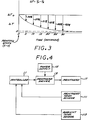
- FIG. 3 is a graph schematically illustrating the cool down characteristic of an illustrative example of a thermal ink jet printhead utilized with the invention. The graph is utilized to determine the amount of warm-up pulsing required as a function of idle time.
- FIG. 4 is a schematic block diagram of the thermal ink jet printer components for implementing a further embodiment of the subject invention.
- FIG. 5 is a flow diagram that sets forth a procedure for calculating and applying printhead warm-up pulses with the printer of FIG. 4.
- a controller 11 receives print data input and processes the print data to provide print control information to printhead driver circuitry 13.
- the printhead driver circuitry 13 receives power from a power supply 15 and drives the individual ink drop firing resistors of a printhead 17.
- the controller 11 which can comprise a microprocessor architecture in accordance with known controller structures, provides control pulses representative of the drive pulses to be produced by the printhead driver circuitry 13.
- the controller provides control pulses having the desired pulse width and pulse frequency, and the printhead driver circuitry produces drive voltage pulses of the same width and frequency, and with an amplitude determined by the power supply 15.
- the controller provides pulse width modulation information, while the amplitude of the voltage pulses is determined by the driver circuitry 13 and the power supply 15.
- controller 11 would typically provide other functions such as control of the printhead carriage (not shown) and control of movement of the print media.
- the controller 11 causes the printhead ink drop firing resistors to be driven with warm-up voltage pulses prior to proceeding with printing if the printhead has been idle for more than a predetermined amount of time after last printing.
- the warm-up pulses provide energy that is insufficient to cause ink drop firing, and therefore cause a rapid increase in the printhead temperature since no ink drop firing occurs.
- Ink drop firing is an important mechanism for printhead cooling, so the resistive heating provided by the pulses is very fast and effective when drop firing is inhibited.
- the warm-up voltage pulses have the same amplitude and five times the frequency as the pulses utilized for ink drop firing, but are approximately one-fourth of the width of the threshold or turn-on pulse width necessary for ink drop firing at the ink drop firing pulsing frequency.
- the warm-up pulses can generally be less than one-half the threshold or turn on pulse width at the warm-up pulsing frequency.
- the warm-up pulsing frequency is selected to be higher than the printing pulsing frequency so that warm-up can take place quickly.
- the energy delivered to the printhead is nearly the same for warm up and ink drop firing, but no ink drops are fired during warm-up pulsing since the resistors do not reach a sufficiently high temperature.
- the longer pulse width used for ink drop firing heats the resistor sufficiently to cause the ink to boil, while the shorter pulse width for warm-up does not. While the foregoing has been directed to increasing frequency and reducing pulse width for warm-up pulsing, it should be appreciated that pulse amplitude could alternatively be modified to provide the requisite warm-up energy. Such modification could be made in conjunction with pulsing frequency and/or pulse width changes.
- the appropriate reduction in pulse amplitude can be derived analyzing the energy of the warm-up pulses provided pursuant to the above example of warm-up pulse widths that are less than the ink firing pulse widths.
- the warm-up pulse voltage could be the determined threshold voltage (i.e., the voltage necessary to fire an ink drop) divided by the square root of the factor applied to the pulse width, which in the foregoing example is 4, the square root of which is 2.
- the printhead ink drop firing resistors are driven with warm-up pulses to raise the printhead temperature to be close to the temperature it had when the printing was interrupted; the amount of warm-up pulses required prior to proceeding with the printing operation depends on the duration of the intervening wait or idle time. For a particular pulsing frequency, this number of pulses will determine a pulsing period or interval. Determination of the interval during which warm-up pulses are provided can be by look-up table or by equation, for example.
- FIG. 2 set forth therein is a flow diagram of a printhead warming process in accordance with the invention that is employed when printing is to be continued after the printer is in the idle state, for example, while waiting for further print data.
- a call for printing occurs, and at 48 the elapsed wait time is determined.
- a determination is then made at 51 as to whether the printer wait or idle time has exceeded a certain threshold interval, beyond which the image density shift becomes perceptible. By way of illustrative example, this interval can be 5 seconds. If the wait time did not exceed 5 seconds, printing proceeds at 53. If the wait time exceeded the threshold interval, a determination is made at 55 as to whether a form feed has occurred since the last print operation. If yes, printing proceeds at 53.
- the printhead thermal resistors are driven with warm-up pulses for a time interval that depends on the duration of the wait time being compensated.
- warm-up pulsing duration is determined with reference to a look-up table.
- an equation that determines warm-up pulsing duration as a function of wait time can be utilized. As discussed more fully below, in the absence of a temperature sensor on the printhead, a "most likely" temperature offset (relative to ambient) at the time of interruption is assumed, and the look-up table would be based on that assumption.
- the warm-up pulsing is provided when the printhead has been idle for more than 5 seconds and printing is resumed on the same page that was being printed when interruption of the printing occurred. Otherwise, printing proceeds without warm-up pulsing, for example when a new page is started after printing was interrupted. While warm-up pulsing can be utilized at the start of printing of a new page, it may not be necessary since the change to darker print density on a new page is not as noticeable as a light density band between darker density bands.
- the printhead warm-up techniques of the invention can be implemented in conjunction with a low temperature start up procedure as disclosed in commonly assigned U.S. Patent 4,791,435, issued December 13, 1988, which is incorporated herein by reference. In such implementation, a determination would be made to determine whether a low temperature startup is required. If yes, then the low temperature startup is performed prior to proceeding with printing instead of warm-up pulsing as described herein.
- the differential temperature ⁇ T is the difference between the actual printhead temperature T p and the ambient temperature T a .
- the differential temperature ⁇ T is at ⁇ T0, and then decreases exponentially with time to zero.
- the temperature rise pursuant to warm-up pulsing is generally linear, and therefore the amount of warm-up pulsing is readily determined from (a) the amount of pulsing time required to raise the printhead temperature by ⁇ T0 and (b) the cool down differential temperature characteristic of the printhead.
- the percentage drop of the differential temperature ⁇ T can be determined for different wait times.
- such differential temperature drop percentages can then be applied to the time required to increase the differential temperature from zero to ⁇ T0 to determine the necessary pulsing times for differential temperature drops of less than ⁇ T0.
- a wait time of 10 seconds would call for a pulsing interval of about 57 percent of the time determined necessary to produce a temperature increase of ⁇ T0 in the printhead.
- an equation can be used to determine warm-up pulsing intervals as a function of wait time. Such equation would also be derived from the amount of pulsing time required to raise the printhead temperature by ⁇ T0 and the cool down differential temperature characteristic of the printhead.
- a consideration with the foregoing implementation of the invention is the assumption of a fixed maximum differential temperature ⁇ T0, which may not be appropriate for all operating conditions; if real time temperature measurement can be accomplished in the ink jet printer, such assumption would not be necessary. Only a correlation between the desired temperature increase (i.e.,
- FIG. 4 set forth therein is an implementation of the invention which utilizes the actual printhead temperature and is not limited to a fixed maximum differential temperature.
- the printer of FIG. 4 adds a printhead temperature sensor 111 and an ambient temperature sensor 113 to the printer of FIG. 1.
- FIG. 5 set forth therein is a printhead warming process that is implemented with the components of the printer of FIG. 4.
- the process of FIG. 5 is based on the ambient temperature having been determined at power up, for example.
- the stop of printing is detected, and at 113 the printhead temperature is sensed.
- the temperature rise ⁇ T0 is calculated from the sensed printhead temperature T i and the ambient temperature T a .
- warm-up pulses are applied pursuant to 129 for a duration that depends on the amount of printhead temperature decrease ⁇ T calculated at 121.
- warm-up pulsing duration can be determined by an equation since the temperature rise pursuant to warm up pulsing is generally linear.
- a look-up table having pulsing intervals for different ranges of ⁇ T could be utilized to determine the duration of warm up pulsing required.
Abstract
Description
- The subject invention relates generally to thermal ink jet printers, and is directed more particularly to a technique for maintaining consistently high print quality in the event of unplanned or unforseen delays in printing a particular document or page.
- Thermal ink jet printers utilize thermal ink jet printheads that comprise an array of precision formed nozzles, each of which is in communication with an associated ink containing chamber that receives ink from a reservoir. Each chamber includes an ink drop firing resistor which is located opposite the nozzle so that ink can collect between the ink drop firing resistor and the nozzle. The ink drop firing resistor is selectively heated by voltage pulses to drive ink drops through the associated nozzle opening in the orifice plate. During each pulse, the ink drop firing resistor is rapidly heated, which causes the ink directly adjacent the ink drop firing resistor to vaporize and form a bubble. As the vapor bubble grows, momentum is transferred to the ink between the bubble and the nozzle, which causes such ink to be propelled through the nozzle and onto the print media.
- A consideration with the operation of thermal ink jet printheads is the variation in print density that results from the printhead cooling that takes place during delays that occur while printing a particular output. Such variation in print density obtains because the physical properties of the ink (most notably the viscosity) are temperature-dependent. Volume of the ejected drop and spot size on the media depend on the physical properties of the ink, and hence on the ink temperature. Finally, the ink temperature and the printhead temperature are very nearly the same; so the printhead temperature determines the ink temperature, which determines the ink properties, which determine the image density on the media.
- If the printing of a particular output such as a graphics image is not accomplished generally continuously, for example, wherein the printer has to repeatedly wait until further data is received, print density shifts occur, which generally look like bands of different print densities across the printed output. The occurrence of such print density shifts is sometimes called "wait time banding."
- The problem of wait time banding has been addressed by suggesting that applications software should be faster to reduce wait times. While such approach might alleviate wait time banding to some degree, it requires various parties to address the problem, and moreover would probably not address the development of higher speed thermal ink jet printers with which the wait time banding problem would be more aggravated.
- It would therefore be an advantage to provide a thermal ink jet printer that reduces print density shifts caused by printer wait times that occur when the printer has to wait for more print data.
- The foregoing and other advantages are provided by the invention in a thermal ink jet printer that includes a thermal ink jet printhead having a plurality of ink jet firing resistors, and drive circuitry for applying, prior to continuation of printing, printhead warming energy to the ink jet printhead, preferably to the resistors at a power level that is insufficient to cause ink drop firing but sufficient to cause a relatively fast increase in printhead temperature. More particularly, if the printhead has been idle for more than a predetermined amount of time, the driver circuitry provides to the ink drop firing resistors pulses having power that is insufficient to cause ink ejection, with the amount of warm-up pulsing dependent on the length of idle time. As a result of the low power warming pulses, the temperature of the printhead is raised to approximately the same level it had while printing.
- The advantages and features of the disclosed invention will readily be appreciated by persons skilled in the art from the following detailed description when read in conjunction with the drawing wherein:
- FIG. 1 is a schematic block diagram of the thermal ink jet printer components for implementing the subject invention.
- FIG. 2 is a flow diagram that sets forth a procedure for calculating and applying printhead warm-up pulses to a thermal ink jet printhead with the printer of FIG. 1.
- FIG. 3 is a graph schematically illustrating the cool down characteristic of an illustrative example of a thermal ink jet printhead utilized with the invention. The graph is utilized to determine the amount of warm-up pulsing required as a function of idle time.
- FIG. 4 is a schematic block diagram of the thermal ink jet printer components for implementing a further embodiment of the subject invention.
- FIG. 5 is a flow diagram that sets forth a procedure for calculating and applying printhead warm-up pulses with the printer of FIG. 4.
- In the following detailed description and in the several figures of the drawing, like elements are identified with like reference numerals.
- Referring now to FIG. 1, shown therein are components of a thermal ink jet printer that employs the techniques of the invention. A controller 11 receives print data input and processes the print data to provide print control information to
printhead driver circuitry 13. Theprinthead driver circuitry 13 receives power from apower supply 15 and drives the individual ink drop firing resistors of aprinthead 17. - More particularly, the controller 11, which can comprise a microprocessor architecture in accordance with known controller structures, provides control pulses representative of the drive pulses to be produced by the
printhead driver circuitry 13. By way of illustrative example, the controller provides control pulses having the desired pulse width and pulse frequency, and the printhead driver circuitry produces drive voltage pulses of the same width and frequency, and with an amplitude determined by thepower supply 15. Essentially, the controller provides pulse width modulation information, while the amplitude of the voltage pulses is determined by thedriver circuitry 13 and thepower supply 15. - As with known controller structures, the controller 11 would typically provide other functions such as control of the printhead carriage (not shown) and control of movement of the print media.
- In accordance with the invention, the controller 11 causes the printhead ink drop firing resistors to be driven with warm-up voltage pulses prior to proceeding with printing if the printhead has been idle for more than a predetermined amount of time after last printing. The warm-up pulses provide energy that is insufficient to cause ink drop firing, and therefore cause a rapid increase in the printhead temperature since no ink drop firing occurs. Ink drop firing is an important mechanism for printhead cooling, so the resistive heating provided by the pulses is very fast and effective when drop firing is inhibited.
- By way of illustrative example, the warm-up voltage pulses have the same amplitude and five times the frequency as the pulses utilized for ink drop firing, but are approximately one-fourth of the width of the threshold or turn-on pulse width necessary for ink drop firing at the ink drop firing pulsing frequency. By controlling the warm-up pulses to be approximately one-fourth the width of the turn-on pulse width ensures that ink drop firing does not occur pursuant to the application of warm-up pulses. Depending upon the characteristics of the printhead, the warm-up pulses can generally be less than one-half the threshold or turn on pulse width at the warm-up pulsing frequency. The warm-up pulsing frequency is selected to be higher than the printing pulsing frequency so that warm-up can take place quickly.
- The energy delivered to the printhead is nearly the same for warm up and ink drop firing, but no ink drops are fired during warm-up pulsing since the resistors do not reach a sufficiently high temperature. In particular, the longer pulse width used for ink drop firing heats the resistor sufficiently to cause the ink to boil, while the shorter pulse width for warm-up does not. While the foregoing has been directed to increasing frequency and reducing pulse width for warm-up pulsing, it should be appreciated that pulse amplitude could alternatively be modified to provide the requisite warm-up energy. Such modification could be made in conjunction with pulsing frequency and/or pulse width changes. The appropriate reduction in pulse amplitude can be derived analyzing the energy of the warm-up pulses provided pursuant to the above example of warm-up pulse widths that are less than the ink firing pulse widths. By way of illustrative example, for a warm-up pulse width that is the same as the ink firing pulse width, the warm-up pulse voltage could be the determined threshold voltage (i.e., the voltage necessary to fire an ink drop) divided by the square root of the factor applied to the pulse width, which in the foregoing example is 4, the square root of which is 2.
- The printhead ink drop firing resistors are driven with warm-up pulses to raise the printhead temperature to be close to the temperature it had when the printing was interrupted; the amount of warm-up pulses required prior to proceeding with the printing operation depends on the duration of the intervening wait or idle time. For a particular pulsing frequency, this number of pulses will determine a pulsing period or interval. Determination of the interval during which warm-up pulses are provided can be by look-up table or by equation, for example.
- Turning now to FIG. 2, set forth therein is a flow diagram of a printhead warming process in accordance with the invention that is employed when printing is to be continued after the printer is in the idle state, for example, while waiting for further print data. At 46 a call for printing occurs, and at 48 the elapsed wait time is determined. A determination is then made at 51 as to whether the printer wait or idle time has exceeded a certain threshold interval, beyond which the image density shift becomes perceptible. By way of illustrative example, this interval can be 5 seconds. If the wait time did not exceed 5 seconds, printing proceeds at 53. If the wait time exceeded the threshold interval, a determination is made at 55 as to whether a form feed has occurred since the last print operation. If yes, printing proceeds at 53.
- If the determination at 55 is no, a form feed did not occur since the last print operation, the printhead thermal resistors are driven with warm-up pulses for a time interval that depends on the duration of the wait time being compensated. By way of illustrative example, such warm-up pulsing duration is determined with reference to a look-up table. Alternatively, an equation that determines warm-up pulsing duration as a function of wait time can be utilized. As discussed more fully below, in the absence of a temperature sensor on the printhead, a "most likely" temperature offset (relative to ambient) at the time of interruption is assumed, and the look-up table would be based on that assumption.
- After the printhead firing resistors are driven with warm-up pulses pursuant at 57, printing proceeds at 53. Essentially, the warm-up pulsing is provided when the printhead has been idle for more than 5 seconds and printing is resumed on the same page that was being printed when interruption of the printing occurred. Otherwise, printing proceeds without warm-up pulsing, for example when a new page is started after printing was interrupted. While warm-up pulsing can be utilized at the start of printing of a new page, it may not be necessary since the change to darker print density on a new page is not as noticeable as a light density band between darker density bands.
- The printhead warm-up techniques of the invention can be implemented in conjunction with a low temperature start up procedure as disclosed in commonly assigned U.S. Patent 4,791,435, issued December 13, 1988, which is incorporated herein by reference. In such implementation, a determination would be made to determine whether a low temperature startup is required. If yes, then the low temperature startup is performed prior to proceeding with printing instead of warm-up pulsing as described herein.
- Referring now to FIG. 3, set forth therein is a graph of the cool down differential temperature characteristic of an illustrative example of a thermal printhead having a thermal time constant of 12 seconds. The differential temperature ΔT is the difference between the actual printhead temperature Tp and the ambient temperature Ta. At the stop of printing, the differential temperature ΔT is at ΔT₀, and then decreases exponentially with time to zero.
- The temperature rise pursuant to warm-up pulsing is generally linear, and therefore the amount of warm-up pulsing is readily determined from (a) the amount of pulsing time required to raise the printhead temperature by ΔT₀ and (b) the cool down differential temperature characteristic of the printhead. For example, as indicated in FIG. 3, the percentage drop of the differential temperature ΔT can be determined for different wait times. For warm-up pulses having predetermined amplitude, width and frequency characteristics, such differential temperature drop percentages can then be applied to the time required to increase the differential temperature from zero to ΔT₀ to determine the necessary pulsing times for differential temperature drops of less than ΔT₀. Thus, relative to a printhead having the characteristic set forth in FIG. 3, a wait time of 10 seconds would call for a pulsing interval of about 57 percent of the time determined necessary to produce a temperature increase of ΔT₀ in the printhead.
- Set forth in the following table are look-up table values for pulse time intervals for different wait time ranges for a Hewlett Packard Model No. 51605A as utilized with warm-up pulses having an amplitude of 10.5 volts, a pulse width of 1.3µ seconds, and a pulse frequency of 15,000 Hz, and assuming a ΔT₀ of 4 degrees C.

- Alternatively to the look-up table, an equation can be used to determine warm-up pulsing intervals as a function of wait time. Such equation would also be derived from the amount of pulsing time required to raise the printhead temperature by ΔT₀ and the cool down differential temperature characteristic of the printhead.
- A consideration with the foregoing implementation of the invention is the assumption of a fixed maximum differential temperature ΔT₀, which may not be appropriate for all operating conditions; if real time temperature measurement can be accomplished in the ink jet printer, such assumption would not be necessary. Only a correlation between the desired temperature increase (i.e., |ΔT|) and energy is necessary to achieve that temperature increase.
- Referring now to FIG. 4, set forth therein is an implementation of the invention which utilizes the actual printhead temperature and is not limited to a fixed maximum differential temperature. The printer of FIG. 4 adds a printhead temperature sensor 111 and an
ambient temperature sensor 113 to the printer of FIG. 1. - Turning now to FIG. 5, set forth therein is a printhead warming process that is implemented with the components of the printer of FIG. 4. The process of FIG. 5 is based on the ambient temperature having been determined at power up, for example. At 111 the stop of printing is detected, and at 113 the printhead temperature is sensed. The temperature rise ΔT₀ is calculated from the sensed printhead temperature Ti and the ambient temperature Ta.
- At 117 a determination is made as to whether printing is to be resumed. If no, the determination is repeated. If the determination at 117 is yes, printing is to be resumed, the printhead temperature Tf is sensed at 119. At 121 the decrease in printhead temperature ΔT is calculated from the printhead temperature Tf sensed at 119 and the printhead temperature Ti sensed at the stop of printing.
- At 123 at determination is made as to whether the decrease in printhead temperature ΔT is greater than 34% of the printhead temperature increase ΔT₀ relative to ambient temperature. If no, printing proceeds at 125.
- If the determination at 123 is yes, the decrease in printhead temperature ΔT is greater than 34% of the printhead temperature increase ΔT₀ relative to ambient temperature, a determination is made at 127 as to whether a form feed has occurred since printing stopped at 111. If yes, printing proceeds at 125.
- If the determination at 127 is no, a form feed did not occur since printing stopped at 111, warm-up pulses are applied pursuant to 129 for a duration that depends on the amount of printhead temperature decrease ΔT calculated at 121. By way of illustrative example, such warm-up pulsing duration can be determined by an equation since the temperature rise pursuant to warm up pulsing is generally linear. For the Hewlett-Packard printhead and warm up pulsing parameters identified above relative to the look-up table for the implementation without a temperature sensor, the warm up pulsing interval would be:

- Alternatively, a look-up table having pulsing intervals for different ranges of ΔT could be utilized to determine the duration of warm up pulsing required.
- The foregoing has been a disclosure of a thermal ink jet printer that compensates for printhead cool down that adversely affects print quality, and is advantageously implemented by modification of existing printhead pulsing circuitry and/or pulsing control firmware.
Claims (14)
- A thermal ink jet printer comprising:
a thermal ink jet printhead having a plurality of ink drop firing resistors responsive to ink drop firing pulses having a selected frequency and pulse width for causing the ejection of ink drops; characterised by control means for applying to the printhead electrical energy sufficient to cause warming of the printhead to a pre-determined level but which is insufficient to cause ink drop firing. - A thermal ink jet printer as claimed in claim 1, wherein said electrical energy is applied to the firing resistors.
- A thermal ink jet printer as claimed in claim 2, wherein said electrical energy is in the form of warming pulses having a pulse width insufficient to cause ink drop firing, said pulses being applied for a time interval that depends on the amount of time that has elapsed since printing by said printhead last occurred.
- The thermal ink jet printer of claim 3 wherein said control means provides warming pulses having the same amplitude as the ink drop firing pulses and a frequency that is greater than that of ink drop firing pulses.
- The thermal ink jet printer of claim 3 or 4 wherein the pulse width of said warming pulses is less than one-half the pulse width necessary to achieve ink drop firing at the warm-up pulsing frequency.
- The thermal ink jet printer of claim 5 wherein the pulse width of the warming pulses is approximately one-fourth the pulse width necessary to achieve ink drop firing at the warming pulse frequency.
- A method for preventing print quality deterioration due to a thermal ink jet printhead wait time, the method comprising:
determining whether the printhead has been waiting for longer than a pre-determined time.
applying to the printhead electrical energy sufficient to cause warming of the printhead to a pre-determined level but which is insufficient to cause ink drop firing. - A method for preventing print quality deterioration due to thermal ink jet printhead wait time, the method comprising the steps of:
sensing printhead temperature upon the stop of printing;
determining whether printing is to be resumed;
if printing is to be resumed, sensing the printhead temperature and determining whether the printhead temperature has decreased by at least a pre-determined amount;
if the printhead temperature has decreased by a predetermined amount, determining whether a form feed has occurred since printing stopped;
if a form feed has not occurred since printing stopped, applying to the printhead electrical energy sufficient to cause warming of the printhead to a pre-determined level but which is insufficient to cause ink drop firing; and
continuing with printing after (a) it is determined that the printhead temperature did not decrease by at least the pre-determined amount, (b) it is determined that a form feed occurred since printing stopped, or (c) the printhead was heated with electrical energy as above. - A method as claimed in claim 7 or 8, comprising applying the electrical energy to the firing resistors.
- A method as claimed in claim 9, comprising driving the ink firing resistors of the printhead with warming pulses having a width that is insufficient to cause ink drop firing for a warming time period that depends on the amount of time that has elapsed since printing by the printhead last occurred.
- A method as claimed in claim 9 comprising driving the ink firing resistors of the printhead with warming pulses having a width that is insufficient to cause ink drop firing for a warming time period that depends on the amount of decrease of the printhead temperature that occurred between the stop of printing and the detection that printing is to be resumed.
- The method of claim 11 wherein the warm-up pulses have the same amplitude as ink drop firing pulses and a frequency greater than that of the ink drop firing pulses.
- The method of claim 12 wherein the pulse width of the warm-up pulses is less than one-half of the pulse width necessary to achieve ink drop firing at the warming pulse frequency.
- The method of claim 13 wherein the pulse width of the warm-up pulses is approximately one-fourth the pulse width necessary to achieve ink drop firing at the warming pulse frequency.
Applications Claiming Priority (2)
| Application Number | Priority Date | Filing Date | Title |
|---|---|---|---|
| US583297 | 1990-09-14 | ||
| US07/583,297 US5109234A (en) | 1990-09-14 | 1990-09-14 | Printhead warming method to defeat wait-time banding |
Publications (3)
| Publication Number | Publication Date |
|---|---|
| EP0475638A2 true EP0475638A2 (en) | 1992-03-18 |
| EP0475638A3 EP0475638A3 (en) | 1992-05-20 |
| EP0475638B1 EP0475638B1 (en) | 1996-01-10 |
Family
ID=24332508
Family Applications (1)
| Application Number | Title | Priority Date | Filing Date |
|---|---|---|---|
| EP91307897A Expired - Lifetime EP0475638B1 (en) | 1990-09-14 | 1991-08-29 | Thermal ink jet printer |
Country Status (4)
| Country | Link |
|---|---|
| US (1) | US5109234A (en) |
| EP (1) | EP0475638B1 (en) |
| DE (1) | DE69116277T2 (en) |
| HK (1) | HK162896A (en) |
Cited By (9)
| Publication number | Priority date | Publication date | Assignee | Title |
|---|---|---|---|---|
| EP0650836A2 (en) * | 1993-10-27 | 1995-05-03 | Hewlett-Packard Company | Temperature control of thermal ink-jet print heads by using synchronous non-nucleating pulses |
| EP0658429A2 (en) * | 1993-12-14 | 1995-06-21 | Hewlett-Packard Company | Control circuit for regulating temperature in an ink-jet print-head |
| EP0670219A2 (en) * | 1994-03-04 | 1995-09-06 | Canon Kabushiki Kaisha | Thermal ink jet printing method and apparatus |
| EP0694392A3 (en) * | 1994-07-29 | 1996-07-31 | Canon Kk | Ink jet printing method and apparatus therefor |
| EP0709196A3 (en) * | 1994-10-27 | 1996-09-04 | Canon Kk | Print head, and print method and apparatus using the same |
| US5736995A (en) * | 1991-05-01 | 1998-04-07 | Hewlett-Packard Company | Temperature control of thermal inkjet printheads by using synchronous non-nucleating pulses |
| EP1077130A2 (en) * | 1999-08-18 | 2001-02-21 | Seiko Epson Corporation | Ink jet recording apparatus and ink jet recording method |
| EP1176016A3 (en) * | 2000-07-26 | 2003-07-02 | Francotyp-Postalia AG & Co. KG | Device and automated adjustment method for warming cycles of inkjet heads |
| CN112776492A (en) * | 2020-12-31 | 2021-05-11 | 苏州工业园区鑫海胜电子有限公司 | Printing method without physical grating |
Families Citing this family (39)
| Publication number | Priority date | Publication date | Assignee | Title |
|---|---|---|---|---|
| US5689292A (en) * | 1990-08-14 | 1997-11-18 | Canon Kabushiki Kaisha | Multi-step heating of a recording head |
| US5894314A (en) * | 1991-01-18 | 1999-04-13 | Canon Kabushiki Kaisha | Ink jet recording apparatus using thermal energy |
| JP2980444B2 (en) * | 1991-01-19 | 1999-11-22 | キヤノン株式会社 | Liquid ejector having bubble introduction mechanism in liquid chamber, recording apparatus and recording method using the same |
| JP2974487B2 (en) * | 1991-03-20 | 1999-11-10 | キヤノン株式会社 | Recording device |
| US5459498A (en) * | 1991-05-01 | 1995-10-17 | Hewlett-Packard Company | Ink-cooled thermal ink jet printhead |
| US5168284A (en) * | 1991-05-01 | 1992-12-01 | Hewlett-Packard Company | Printhead temperature controller that uses nonprinting pulses |
| US5673069A (en) * | 1991-05-01 | 1997-09-30 | Hewlett-Packard Company | Method and apparatus for reducing the size of drops ejected from a thermal ink jet printhead |
| CA2074906C (en) * | 1991-08-01 | 2000-09-12 | Hiromitsu Hirabayashi | Ink jet recording apparatus having temperature control function |
| US6076919A (en) * | 1991-08-12 | 2000-06-20 | Canon Kabushiki Kaisha | Jet recording method |
| JP3376036B2 (en) * | 1993-09-24 | 2003-02-10 | キヤノン株式会社 | Ink jet recording apparatus and recording method |
| US5524993A (en) * | 1993-10-06 | 1996-06-11 | Monarch Marking Systems, Inc. | Automatic print speed control for a barcode printer |
| JP3259748B2 (en) * | 1994-03-31 | 2002-02-25 | セイコーエプソン株式会社 | Ink jet recording device |
| JPH07314763A (en) * | 1994-05-30 | 1995-12-05 | Riso Kagaku Corp | Controlling method of thermal head for thermosensitive plate making and device therefor |
| US5710581A (en) * | 1994-07-29 | 1998-01-20 | Hewlett-Packard Company | Inkjet printhead having intermittent nozzle clearing |
| JPH09193395A (en) * | 1996-01-11 | 1997-07-29 | Brother Ind Ltd | Recording apparatus |
| US5847674A (en) * | 1996-05-02 | 1998-12-08 | Moore Business Forms, Inc. | Apparatus and methods for maintaining optimum print quality in an ink jet printer after periods of inactivity |
| US5751312A (en) * | 1996-09-04 | 1998-05-12 | Lexmark International, Inc. | Method of inhibiting a print artifact associated with a printer pause |
| US5815180A (en) * | 1997-03-17 | 1998-09-29 | Hewlett-Packard Company | Thermal inkjet printhead warming circuit |
| US6231153B1 (en) | 1997-04-25 | 2001-05-15 | Hewlett-Packard Company | Method and apparatus for controlling an ink-jet print head temperature |
| AUPP653998A0 (en) * | 1998-10-16 | 1998-11-05 | Silverbrook Research Pty Ltd | Micromechanical device and method (ij46B) |
| AUPP654598A0 (en) * | 1998-10-16 | 1998-11-05 | Silverbrook Research Pty Ltd | Micromechanical device and method (ij46h) |
| US6386674B1 (en) | 1997-10-28 | 2002-05-14 | Hewlett-Packard Company | Independent power supplies for color inkjet printers |
| US6154229A (en) | 1997-10-28 | 2000-11-28 | Hewlett-Packard Company | Thermal ink jet print head and printer temperature control apparatus and method |
| US6290333B1 (en) | 1997-10-28 | 2001-09-18 | Hewlett-Packard Company | Multiple power interconnect arrangement for inkjet printhead |
| US6183056B1 (en) | 1997-10-28 | 2001-02-06 | Hewlett-Packard Company | Thermal inkjet printhead and printer energy control apparatus and method |
| US7182431B2 (en) * | 1999-10-19 | 2007-02-27 | Silverbrook Research Pty Ltd | Nozzle arrangement |
| US7216956B2 (en) * | 1998-10-16 | 2007-05-15 | Silverbrook Research Pty Ltd | Printhead assembly with power and ground connections along single edge |
| US6902255B1 (en) * | 1998-10-16 | 2005-06-07 | Silverbrook Research Pty Ltd | Inkjet printers |
| US6805435B2 (en) * | 1998-10-16 | 2004-10-19 | Silverbrook Research Pty Ltd | Printhead assembly with an ink distribution arrangement |
| AUPP702498A0 (en) * | 1998-11-09 | 1998-12-03 | Silverbrook Research Pty Ltd | Image creation method and apparatus (ART77) |
| US6986566B2 (en) | 1999-12-22 | 2006-01-17 | Eastman Kodak Company | Liquid emission device |
| US6669324B1 (en) | 2002-11-25 | 2003-12-30 | Lexmark International, Inc. | Method and apparatus for optimizing a relationship between fire energy and drop velocity in an imaging device |
| US20050179739A1 (en) * | 2004-02-17 | 2005-08-18 | Fuji Xerox Co., Ltd. | Methods and apparatus for thermal fluid jet drop volume control using variable length pre-pulses |
| US7604321B2 (en) * | 2006-10-10 | 2009-10-20 | Silverbrook Research Pty Ltd | Thermal inkjet printhead with de-clog firing mode |
| US8194254B2 (en) * | 2007-01-30 | 2012-06-05 | Hewlett-Packard Development Company, L.P. | Print device preconditioning |
| JP2008246883A (en) * | 2007-03-30 | 2008-10-16 | Brother Ind Ltd | Image forming device |
| US20090033950A1 (en) * | 2007-07-30 | 2009-02-05 | Hewlett-Packard Development | Printhead preconditioning trigger |
| JP2011178041A (en) * | 2010-03-01 | 2011-09-15 | Seiko Epson Corp | Control device and liquid jetting apparatus |
| JP6579833B2 (en) * | 2015-07-06 | 2019-09-25 | キヤノン株式会社 | Liquid ejection apparatus and method for maintaining heat of liquid ejection head |
Citations (3)
| Publication number | Priority date | Publication date | Assignee | Title |
|---|---|---|---|---|
| GB2159465A (en) * | 1984-05-25 | 1985-12-04 | Canon Kk | Generating droplets by heating |
| GB2169855A (en) * | 1984-12-21 | 1986-07-23 | Canon Kk | Liquid-jet recorder |
| US4910528A (en) * | 1989-01-10 | 1990-03-20 | Hewlett-Packard Company | Ink jet printer thermal control system |
Family Cites Families (5)
| Publication number | Priority date | Publication date | Assignee | Title |
|---|---|---|---|---|
| US4463359A (en) * | 1979-04-02 | 1984-07-31 | Canon Kabushiki Kaisha | Droplet generating method and apparatus thereof |
| US4490728A (en) * | 1981-08-14 | 1984-12-25 | Hewlett-Packard Company | Thermal ink jet printer |
| JPS60219060A (en) * | 1984-04-17 | 1985-11-01 | Canon Inc | Liquid injection recorder |
| GB2169856B (en) * | 1984-12-28 | 1989-10-25 | Canon Kk | Liquid-discharge recording apparatus and a method of operation thereof |
| US4791435A (en) * | 1987-07-23 | 1988-12-13 | Hewlett-Packard Company | Thermal inkjet printhead temperature control |
-
1990
- 1990-09-14 US US07/583,297 patent/US5109234A/en not_active Expired - Lifetime
-
1991
- 1991-08-29 DE DE69116277T patent/DE69116277T2/en not_active Expired - Lifetime
- 1991-08-29 EP EP91307897A patent/EP0475638B1/en not_active Expired - Lifetime
-
1996
- 1996-08-29 HK HK162896A patent/HK162896A/en not_active IP Right Cessation
Patent Citations (3)
| Publication number | Priority date | Publication date | Assignee | Title |
|---|---|---|---|---|
| GB2159465A (en) * | 1984-05-25 | 1985-12-04 | Canon Kk | Generating droplets by heating |
| GB2169855A (en) * | 1984-12-21 | 1986-07-23 | Canon Kk | Liquid-jet recorder |
| US4910528A (en) * | 1989-01-10 | 1990-03-20 | Hewlett-Packard Company | Ink jet printer thermal control system |
Cited By (21)
| Publication number | Priority date | Publication date | Assignee | Title |
|---|---|---|---|---|
| US5736995A (en) * | 1991-05-01 | 1998-04-07 | Hewlett-Packard Company | Temperature control of thermal inkjet printheads by using synchronous non-nucleating pulses |
| EP0650836A3 (en) * | 1993-10-27 | 1997-03-12 | Hewlett Packard Co | Temperature control of thermal ink-jet print heads by using synchronous non-nucleating pulses. |
| EP0650836A2 (en) * | 1993-10-27 | 1995-05-03 | Hewlett-Packard Company | Temperature control of thermal ink-jet print heads by using synchronous non-nucleating pulses |
| EP0658429A2 (en) * | 1993-12-14 | 1995-06-21 | Hewlett-Packard Company | Control circuit for regulating temperature in an ink-jet print-head |
| EP0658429A3 (en) * | 1993-12-14 | 1996-03-20 | Hewlett Packard Co | Control circuit for regulating temperature in an ink-jet print-head. |
| EP1336485A3 (en) * | 1994-03-04 | 2004-06-09 | Canon Kabushiki Kaisha | Apparatus and method for correcting a printing head |
| US6409300B2 (en) | 1994-03-04 | 2002-06-25 | Canon Kabushiki Kaisha | Printing head, printing method and apparatus using same, and apparatus and method for correcting said printing head |
| EP0670219A3 (en) * | 1994-03-04 | 1996-08-07 | Canon Kk | Thermal ink jet printing method and apparatus. |
| EP0670219A2 (en) * | 1994-03-04 | 1995-09-06 | Canon Kabushiki Kaisha | Thermal ink jet printing method and apparatus |
| US6116714A (en) * | 1994-03-04 | 2000-09-12 | Canon Kabushiki Kaisha | Printing head, printing method and apparatus using same, and apparatus and method for correcting said printing head |
| US6616257B2 (en) | 1994-03-04 | 2003-09-09 | Canon Kabushiki Kaisha | Printing head, printing method and apparatus using same, and apparatus and method for correcting said printing head |
| EP0694392A3 (en) * | 1994-07-29 | 1996-07-31 | Canon Kk | Ink jet printing method and apparatus therefor |
| US5838340A (en) * | 1994-07-29 | 1998-11-17 | Canon Kabushiki Kaisha | Ink-jet printing method and apparatus therefor |
| US5867200A (en) * | 1994-10-27 | 1999-02-02 | Canon Kabushiki Kaisha | Print head, and print pre-heat method and apparatus using the same |
| EP0709196A3 (en) * | 1994-10-27 | 1996-09-04 | Canon Kk | Print head, and print method and apparatus using the same |
| EP1077130A3 (en) * | 1999-08-18 | 2001-05-16 | Seiko Epson Corporation | Ink jet recording apparatus and ink jet recording method |
| US6530636B1 (en) | 1999-08-18 | 2003-03-11 | Seiko Epson Corporation | Ink jet recording apparatus and ink jet recording method |
| EP1077130A2 (en) * | 1999-08-18 | 2001-02-21 | Seiko Epson Corporation | Ink jet recording apparatus and ink jet recording method |
| EP1176016A3 (en) * | 2000-07-26 | 2003-07-02 | Francotyp-Postalia AG & Co. KG | Device and automated adjustment method for warming cycles of inkjet heads |
| US7431415B2 (en) | 2000-07-26 | 2008-10-07 | Francotyp-Postalia Ag & Co. Kg | Arrangement and method for data follow-up for warmup cycles of ink jet print heads |
| CN112776492A (en) * | 2020-12-31 | 2021-05-11 | 苏州工业园区鑫海胜电子有限公司 | Printing method without physical grating |
Also Published As
| Publication number | Publication date |
|---|---|
| EP0475638A3 (en) | 1992-05-20 |
| EP0475638B1 (en) | 1996-01-10 |
| US5109234A (en) | 1992-04-28 |
| DE69116277T2 (en) | 1996-05-23 |
| DE69116277D1 (en) | 1996-02-22 |
| HK162896A (en) | 1996-09-06 |
Similar Documents
| Publication | Publication Date | Title |
|---|---|---|
| EP0475638B1 (en) | Thermal ink jet printer | |
| EP0300634B1 (en) | Thermal inkjet pen temperature control | |
| US5736995A (en) | Temperature control of thermal inkjet printheads by using synchronous non-nucleating pulses | |
| EP0658429B1 (en) | Control circuit for regulating temperature in an ink-jet print-head | |
| US5751302A (en) | Transducer power dissipation control in a thermal ink jet printhead | |
| EP0679517B1 (en) | Liquid ejection printing apparatus | |
| JPH0839807A (en) | Ink jet printing method and apparatus | |
| JP2752491B2 (en) | Liquid jet recording device | |
| EP0692385B1 (en) | Liquid discharging recording head | |
| JPH06210889A (en) | Thermal transfer printing method | |
| EP1022139B1 (en) | Ink jet printers | |
| US6390585B1 (en) | Selectively warming a printhead for optimized performance | |
| JP3402766B2 (en) | Printing apparatus, control method of the printing apparatus, and printing method | |
| US6409298B1 (en) | System and method for controlling current density in thermal printheads | |
| US6527355B1 (en) | Method and apparatus for preventing banding defects caused by drop mass variations in an ink jet printer | |
| EP0600648B1 (en) | Method and apparatus for the control of thermal ink jet printers | |
| JP2986883B2 (en) | Ink jet recording device | |
| JP3222629B2 (en) | Ink jet recording apparatus and ink jet recording method | |
| US6474772B1 (en) | Method of determining thermal turn on energy | |
| JP2004122533A (en) | Inkjet recording device and inkjet recording method | |
| JP3521976B2 (en) | Inkjet printing method and printer | |
| JP2977313B2 (en) | Recording apparatus and recording control method | |
| JP3066924B2 (en) | Ink jet recording device | |
| JPH02235759A (en) | Ink jet recording apparatus | |
| JPH10128958A (en) | Ink jet recording apparatus and temperature control method thereof |
Legal Events
| Date | Code | Title | Description |
|---|---|---|---|
| PUAI | Public reference made under article 153(3) epc to a published international application that has entered the european phase |
Free format text: ORIGINAL CODE: 0009012 |
|
| AK | Designated contracting states |
Kind code of ref document: A2 Designated state(s): DE FR GB IT |
|
| PUAL | Search report despatched |
Free format text: ORIGINAL CODE: 0009013 |
|
| AK | Designated contracting states |
Kind code of ref document: A3 Designated state(s): DE FR GB IT |
|
| 17P | Request for examination filed |
Effective date: 19920923 |
|
| 17Q | First examination report despatched |
Effective date: 19931230 |
|
| GRAA | (expected) grant |
Free format text: ORIGINAL CODE: 0009210 |
|
| AK | Designated contracting states |
Kind code of ref document: B1 Designated state(s): DE FR GB IT |
|
| REF | Corresponds to: |
Ref document number: 69116277 Country of ref document: DE Date of ref document: 19960222 |
|
| ET | Fr: translation filed | ||
| ITF | It: translation for a ep patent filed |
Owner name: SOCIETA' ITALIANA BREVETTI S.P.A. |
|
| PLBE | No opposition filed within time limit |
Free format text: ORIGINAL CODE: 0009261 |
|
| STAA | Information on the status of an ep patent application or granted ep patent |
Free format text: STATUS: NO OPPOSITION FILED WITHIN TIME LIMIT |
|
| 26N | No opposition filed | ||
| REG | Reference to a national code |
Ref country code: GB Ref legal event code: 732E |
|
| REG | Reference to a national code |
Ref country code: FR Ref legal event code: TP |
|
| REG | Reference to a national code |
Ref country code: GB Ref legal event code: IF02 |
|
| PGFP | Annual fee paid to national office [announced via postgrant information from national office to epo] |
Ref country code: IT Payment date: 20100826 Year of fee payment: 20 Ref country code: DE Payment date: 20100827 Year of fee payment: 20 Ref country code: FR Payment date: 20100831 Year of fee payment: 20 |
|
| PGFP | Annual fee paid to national office [announced via postgrant information from national office to epo] |
Ref country code: GB Payment date: 20100825 Year of fee payment: 20 |
|
| REG | Reference to a national code |
Ref country code: DE Ref legal event code: R071 Ref document number: 69116277 Country of ref document: DE |
|
| REG | Reference to a national code |
Ref country code: DE Ref legal event code: R071 Ref document number: 69116277 Country of ref document: DE |
|
| REG | Reference to a national code |
Ref country code: GB Ref legal event code: PE20 Expiry date: 20110828 |
|
| PG25 | Lapsed in a contracting state [announced via postgrant information from national office to epo] |
Ref country code: GB Free format text: LAPSE BECAUSE OF EXPIRATION OF PROTECTION Effective date: 20110828 |
|
| PG25 | Lapsed in a contracting state [announced via postgrant information from national office to epo] |
Ref country code: DE Free format text: LAPSE BECAUSE OF EXPIRATION OF PROTECTION Effective date: 20110830 |