EP0475197A2 - Information recording medium - Google Patents
Information recording medium Download PDFInfo
- Publication number
- EP0475197A2 EP0475197A2 EP91114466A EP91114466A EP0475197A2 EP 0475197 A2 EP0475197 A2 EP 0475197A2 EP 91114466 A EP91114466 A EP 91114466A EP 91114466 A EP91114466 A EP 91114466A EP 0475197 A2 EP0475197 A2 EP 0475197A2
- Authority
- EP
- European Patent Office
- Prior art keywords
- substrates
- cartridge
- recording medium
- substrate
- information recording
- Prior art date
- Legal status (The legal status is an assumption and is not a legal conclusion. Google has not performed a legal analysis and makes no representation as to the accuracy of the status listed.)
- Withdrawn
Links
- 239000000758 substrate Substances 0.000 claims abstract description 50
- 125000006850 spacer group Chemical group 0.000 claims description 11
- 230000003287 optical effect Effects 0.000 abstract description 51
- 238000003780 insertion Methods 0.000 description 17
- 230000037431 insertion Effects 0.000 description 17
- 230000007246 mechanism Effects 0.000 description 15
- 238000005452 bending Methods 0.000 description 3
- 229920005989 resin Polymers 0.000 description 3
- 239000011347 resin Substances 0.000 description 3
- 239000000853 adhesive Substances 0.000 description 2
- 230000002950 deficient Effects 0.000 description 2
- 238000000034 method Methods 0.000 description 2
- 230000003449 preventive effect Effects 0.000 description 2
- 239000011435 rock Substances 0.000 description 2
- 239000004809 Teflon Substances 0.000 description 1
- 229920006362 Teflon® Polymers 0.000 description 1
- 230000001070 adhesive effect Effects 0.000 description 1
- 238000010276 construction Methods 0.000 description 1
- 230000000994 depressogenic effect Effects 0.000 description 1
- 239000002184 metal Substances 0.000 description 1
- 238000000465 moulding Methods 0.000 description 1
- 238000000926 separation method Methods 0.000 description 1
- 229920003002 synthetic resin Polymers 0.000 description 1
- 239000000057 synthetic resin Substances 0.000 description 1
Images


Classifications
-
- G—PHYSICS
- G11—INFORMATION STORAGE
- G11B—INFORMATION STORAGE BASED ON RELATIVE MOVEMENT BETWEEN RECORD CARRIER AND TRANSDUCER
- G11B17/00—Guiding record carriers not specifically of filamentary or web form, or of supports therefor
- G11B17/02—Details
- G11B17/04—Feeding or guiding single record carrier to or from transducer unit
- G11B17/041—Feeding or guiding single record carrier to or from transducer unit specially adapted for discs contained within cartridges
- G11B17/043—Direct insertion, i.e. without external loading means
- G11B17/0436—Direct insertion, i.e. without external loading means with opening mechanism of the cartridge shutter
-
- G—PHYSICS
- G11—INFORMATION STORAGE
- G11B—INFORMATION STORAGE BASED ON RELATIVE MOVEMENT BETWEEN RECORD CARRIER AND TRANSDUCER
- G11B23/00—Record carriers not specific to the method of recording or reproducing; Accessories, e.g. containers, specially adapted for co-operation with the recording or reproducing apparatus ; Intermediate mediums; Apparatus or processes specially adapted for their manufacture
- G11B23/0014—Record carriers not specific to the method of recording or reproducing; Accessories, e.g. containers, specially adapted for co-operation with the recording or reproducing apparatus ; Intermediate mediums; Apparatus or processes specially adapted for their manufacture record carriers not specifically of filamentary or web form
- G11B23/0021—Record carriers not specific to the method of recording or reproducing; Accessories, e.g. containers, specially adapted for co-operation with the recording or reproducing apparatus ; Intermediate mediums; Apparatus or processes specially adapted for their manufacture record carriers not specifically of filamentary or web form discs
- G11B23/0028—Details
- G11B23/0035—Details means incorporated in the disc, e.g. hub, to enable its guiding, loading or driving
-
- G—PHYSICS
- G11—INFORMATION STORAGE
- G11B—INFORMATION STORAGE BASED ON RELATIVE MOVEMENT BETWEEN RECORD CARRIER AND TRANSDUCER
- G11B23/00—Record carriers not specific to the method of recording or reproducing; Accessories, e.g. containers, specially adapted for co-operation with the recording or reproducing apparatus ; Intermediate mediums; Apparatus or processes specially adapted for their manufacture
- G11B23/02—Containers; Storing means both adapted to cooperate with the recording or reproducing means
- G11B23/03—Containers for flat record carriers
- G11B23/032—Containers for flat record carriers for rigid discs
- G11B23/0321—Containers for flat record carriers for rigid discs rigid cartridges for single discs
-
- G—PHYSICS
- G11—INFORMATION STORAGE
- G11B—INFORMATION STORAGE BASED ON RELATIVE MOVEMENT BETWEEN RECORD CARRIER AND TRANSDUCER
- G11B7/00—Recording or reproducing by optical means, e.g. recording using a thermal beam of optical radiation by modifying optical properties or the physical structure, reproducing using an optical beam at lower power by sensing optical properties; Record carriers therefor
- G11B7/24—Record carriers characterised by shape, structure or physical properties, or by the selection of the material
Definitions
- Fig. 14 shows a cartridge 81a which contains a single-sided optical disk 51a.
- This single-sided disk cartridge 81a has exposure windows and a shutter 84 identical with those of the aforementioned double-sided disk cartridge.
- An inclined portion 17 and recesses 18 for preventing wrong insertion of the cartridge 81 is formed on that side of the front end portion of the cartridge 81a which is situated opposite to the side of the pin engaging portion 87 of the slider 85.
- the cartridge 81a is thinner than the cartridge 81 for the double-sided optical disk. Since other portions of the cartridge 81a are constructed in the same manner as those of the cartridge 81, a detailed description of the arrangement of those portions is omitted.
Abstract
Description
- The present invention relates to an information recording medium, such as an optical disk, for optically recording and reproducing information.
- In general, an information recording medium, e.g., an optical disk for double-sided recording and reproducing is formed by joining two substrates, each having an information recording and reproducing region, and pasting a hub, for use as a supported body, on the out side of each substrate. The optical disk is rotated in a manner such that its hub is supported on a turntable as supporting means which is arranged in an optical disk apparatus, for example.
- In the optical disk constructed in this manner, the hub sometimes may be separated from the substrate due to defective bonding. In such a case, only the hub is left in the disk apparatus, and fails to be removed therefrom. In this state, a user cannot repair the disk apparatus.
- The present invention has been contrived in consideration of these circumstances, and its object is to provide a safe information recording medium which has no possibility of damaging a recording and reproducing apparatus due to its hub's separation.
- In order to solve the above problem, an information recording medium according to the present invention, which is supported by means of supporting means for rotation and is designed to record or reproduce information when irradiated, comprises: two substrates each having a recording region on which information is recorded and pasted together facing each other; and an engagement portion for engaging the supporting means, the engagement portion including a projection clamped between the substrates.
- With this arrangement, even if the engagement portion, which constitutes the supported body, is separated from the substrates due to defective bonding, its projection, held between the substrates, prevents the engagement portion from being disengaged from the substrates. According to the information recording medium of the present invention, therefore, there is no possibility of only the engagement portion remaining in the supporting means in the disk apparatus and failing to be removed therefrom in case of a user's repairing the apparatus.
- This invention can be more fully understood from the following detailed description when taken in conjunction with the accompanying drawings, in which:
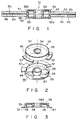
Figs. 1 to 3 show an optical disk according to an embodiment of the present invention, in which: - Fig. 1 is a sectional view of the optical disk,
- Fig. 2 is a perspective view showing hubs of the optical disk, and
- Fig. 3 is a sectional view of one of the hubs;
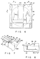
- Fig. 4 is a perspective view of the cartridge,
- Fig. 5 is a perspective view showing a slider of the cartridge,
- Fig. 6 is a plan view of the cartridge,
- Fig. 7 is an enlarged perspective view showing a taper portion of the slider and a taper portion of a shutter, and
- Fig. 8 is a side view showing the taper portions; and
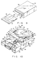
- Fig. 9 is a perspective view showing an outline of the apparatus along with the cartridge,
- Fig. 10 is a perspective view showing the interior of the apparatus with its housing omitted,
- Fig. 11 is a plan view schematically showing a state in which the cartridge is in its initial position in the apparatus,
- Fig. 12 is a plan view schematically showing a state in which the whole cartridge is held in the apparatus,
- Fig. 13 is a perspective view showing a holder frame holding the whole cartridge,
- Fig. 14 is a perspective view showing a cartridge of an optical disk for single-sided recording and reproducing,
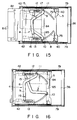
- Fig. 15 is a plan view schematically showing a state in which part of the single-sided disk cartridge is in the apparatus,
- Fig. 16 is a plan view schematically showing a state in which the whole single-sided disk cartridge is held in the apparatus,
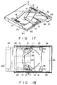
- Fig. 17 is a perspective view showing the holder frame holding the whole single-sided disk cartridge, and
- Fig. 18 is a plan view schematically showing a state in which the single-sided disk cartridge is inserted upside down in the apparatus.
- An embodiment of the present invention will now be described in detail with reference to the accompanying drawings.
- Figs. 1 to 3 show an optical disk for use as an information recording medium according to the embodiment of the present invention, especially a double-sided
optical disk 51 capable of double-sided information recording and reproducing. - The
optical disk 51 comprises two disk-shaped substrates 52 and a pair ofhubs 53 for use as engagement portions. Eachsubstrate 52 is formed of transparent resin, and has a concentric bore 52a in the center. A ring-shapedinformation recording layer 50 is formed coaxially on one surface of eachsubstrate 52. - Each
hub 53 includes aninner cylinder 54, a concentricouter cylinder 55 surrounding thecylinder 54, and a ring-shaped supportingwall 48 connecting the corresponding end portions of the cylinders. Anannular space 56 between the inner andouter cylinders wall 48 constitutes a supporting surface. The outer diameter of theouter cylinder 54 is substantially equal to the diameter of the bore 52a in eachsubstrate 52. A plurality of collar portions (three in number in the present embodiment) 57 are formed intermittently or partially along the outer periphery of an open end portion of theouter cylinder 55, and extend in the circumferential direction. Fixed to the supporting surface 48a is a ring-shapedmagnetic plate 58 which has a bore in the center. - In the present embodiment, the components of each
hub 53 are integrally formed of synthetic resin. Themagnetic plate 58, in particular, has a stepped portion (not shown) around the bore, and is formed integrally with thehub 53 by insert molding. The stepped portion bites into the resin lest themagnetic plate 58 be separated. - Each
hub 53, constructed in this manner, is fixed to itscorresponding substrate 52 in a manner such that itsouter cylinder 55 is fitted into the through hole 52a of the substrate from the side of therecording layer 50 thereof, and itscollar portions 57 are bonded to the recording-layer-side surface of the substrate by means of an adhesive agent. As shown in Fig. 1, theoptical disk 51 is formed by pasting the twosubstrates 52, having thehubs 53 bonded thereto, with aspacer 59 sandwiched between them. In doing this, thesubstrates 52 are joined together with the twohubs 53 deviated from each other lest thecollar portions 57 of the hubs overlap one another. Therefore, thespacer 59 need not be twice as thick as eachcollar portion 57, and must only be as thick as eachportion 57, so that an increase of the mass of the disk can be reduced. Moreover, the capability of a spindle motor (not shown), for use as optical disk rotating means, to control variation in rotation can be improved, so that information can be reproduced from theoptical disk 51 with less jittering. - The
spacer 59 is in the form of a ring coaxial with theoptical disk 51. The outer diameter of thespacer 59 is greater than that of eachrecording layer 50 which forms a recording and reproducing region, and the inner diameter of the spacer is smaller than that of the recording layer. Thus, eachrecording layer 50 is reinforced as a whole by thespacer 59, so that the life performance of thedisk 51 can be improved. Thespacer 59 is a sheet both sides of which are coated with adhesive mass, for example. - After each
substrate 52 and itscorresponding hub 53 are bonded together with their respective centers in alignment, the twosubstrates 52 are pasted on each other with thespacer 59 between them. Accordingly, the center of rotation of eachsubstrate 52 can be easily aligned with that of the spindle motor for driving theoptical disk 51. Since thecollar portions 57 are sandwiched between the twosubstrates 52, moreover, thehubs 53 can never be disengaged from thedisk 51 even if the bond portions between thecollar portions 57 and thesubstrates 52 peel off. In removing theoptical disk 51 from a turntable, for use as disk supporting means of an optical disk apparatus mentioned later, therefore, thehubs 53 can be prevented from coming off and remaining on the turntable. - Referring now to Figs. 4 to 8, a disk cartridge containing the aforementioned double-sided
optical disk 51 will be described. - The
cartridge 81 includes first and secondsymmetrical cartridge halves second halves window 100 through which theoptical disk 51 in thecartridge 81 is exposed to the outside, and which is opened and closed by means of ashutter 84 attached to the cartridge. Thewindow 100 extends close to front end face of thecartridge 81 from the central portion of its corresponding cartridge half, along the direction C of insertion of the cartridge into the disk apparatus. When theshutter 84 is moved aside to open thewindow 100, thehubs 53 and thesubstrates 52 of theoptical disk 51 are partially exposed. Theshutter 84, which is formed by bending a metal plate in the shape of a U, includes a pair of plate portions 84a, individually facing the respective surfaces of the first andsecond halves portion 84b extending between the respective leading ends of the plate portions. Aguide groove 87, which extends in the direction perpendicular to the cartridge insertion direction C, is formed on afront end face 90 of thecartridge 81 on the leading end side with respect to the insertion direction. Aslider 85 of Teflon-based resin is fitted in theguide groove 87, and can slide in the perpendicular direction (direction of arrow A or B in Fig. 6), guided by thegroove 87. The connectingportion 84b of theshutter 84 is fixed to theslider 85 by means ofscrews 86, and the shutter slides together with the slider, thereby opening or closing thewindows 100. Theslider 85 is urged in the direction of arrow A by means of a spring (not shown), and theshutter 84 is normally kept in a closing position shown in Fig. 6. - As shown in Figs. 4 and 5, the
slider 85 is elongated in its sliding direction. An open-closepin engaging portion 87 is formed on one end side of theslider 85. One of paired open-close pins portion 87. When thewindows 100 are closed by theshutter 84, thepin engaging portion 87 is situated on one end side of of thecartridge 81 with respect to the sliding direction. The intermediate portion of theslider 85 constitutes aflat mounting portion 85a to which the connectingportion 84b of theshutter 84 is fixed. Aninclined portion 88 is formed at the other end of theslider 85. The open-close pin taper portion 88. Figs. 7 and 8 show the arrangement of theinclined portion 88 in detail. Theinclined portion 88 has a width substantially equal to the width H of the front end face 90 of thecartridge 81, and is inclined at a predetermined angle to the front end face. At least part of each plate portion 84a of theshutter 84 extends on each side face of theinclined portion 88, and aninclined portion 89 is formed on each extending portion. Eachinclined portion 89 is inclined at an angle narrower than that of theinclined portion 88 to thefront end face 90, and its slanting surface crosses a side edge of the front end face 90 of thecartridge 81 and the slanting surface of theinclined portion 88, as viewed at right angles to the plate portion 84a. - The following is a description of open-close operation for the
shutter 84 of thecartridge 81 constructed in this manner. - When the
cartridge 81, with itsexposure windows 100 closed by theshutter 84, is first inserted into the optical disk apparatus, as mentioned later, the open-close pins cartridge 81 toward the center, along the front end face (or sliding surface for the slider 85). The onepin 10 abuts against thepin engaging portion 87 of theslider 85 at one end side of the front end face 90 of thecartridge 81, and moves toward the other end side of the cartridge (in the direction of arrow B in Fig. 6) while pushing the slider. Thereupon, theshutter 84 also moves in the direction of arrow B, thereby allowing thewindow 100 to open. Theother pin 11 moves in the direction of arrow A, from the other end of the front end face 90 toward the one end side thereof. As it moves in this manner, thepin 11 first engages and runs onto theinclined portions 89 of theslider 85, then engages and runs onto theinclined portion 88 of theslider 85, and moves further toward the one end side. Thus, the other open-close pin 11 is not concerned in the open-close operation for theshutter 84. - In the process of finally running onto the
slider 85, the open-close pin 11 first engages theinclined portions 89 of theshutter 84 without directly engaging theinclined portion 88 of theslider 85. As mentioned before, theinclined portions 89 cross the front end face 90 of thecartridge 81 and theinclined portion 88 of theslider 85. When thepin 11 runs onto theslider 85, therefore, it can smoothly move without hitching at the boundaries betweeninclined portions 89 and thefront end face 90 and between theinclined portions close pin 10, which operates in association with thepin 11, as mentioned later, can be smoothly performed without being interrupted in the middle. If theinclined portions 89 of theshutter 84 are omitted, the boundaries between thefront end face 90 and theinclined portion 88 of theslider 85 should be worked to ensure smoother slopes. Practically, however, the smallest difference in surface level may cause the open-close pin 11 to hitch, thereby hindering the shutter open-close operation of thepin 10. - In the present embodiment, the
inclined portion 88 of theslider 85 has substantially the same width as thefront end face 90, so that the open-close pin 11 can securely run onto theslider 85 from theend face 90 without being disengaged from theinclined portion 88. - If the
cartridge 81 is inserted upside down into the optical disk apparatus, the open-close pin 11 abuts against the open-closepin engaging portion 87 of theslider 85, and the open-close pin 10 runs onto theslider 85, so that thewindow 100 on the other side is opened. - Referring now to Figs. 9 to 18, the optical disk apparatus for recording and reproducing information on the
optical disk 51 in thecartridge 81 with the aforementioned construction will be described. - As shown in Fig. 9, the
optical disk apparatus 72 comprises ahousing 30, and aloading slot 32 for thecartridge 81 is formed in the front face of the housing. As shown in Fig. 10, thehousing 30 contains afirst loading mechanism 73 for horizontally loading thecartridge 81 inserted through theloading slot 32, asecond loading mechanism 74 for vertically loading thecartridge 81 loaded in a predetermined position by themechanism 73, and aturntable 71 for supporting theoptical disk 51 in thecartridge 81. Thehousing 30 further contains a motor (not shown) for rotating theturntable 71, anoptical head 34 for applying light to theoptical disk 51 in thecartridge 81 to record and reproduce information, etc. The following is a description of the first andsecond loading mechanisms - The
first loading mechanism 73 comprises aholder frame 5 and ashutter operating mechanism 4 thereon. Theframe 5, which is formed by bending a plate, includes a rectangular top plate 5a, a pair ofside plates 5b extending downward from two opposite side edges of the top plate, and supportingportions 5c formed by inwardly bending the respective lower end portions of the side plates and facing the top plate in parallel relation. Theframe 5 serves to hold and guide thecartridge 81, inserted through theloading slot 32, in the horizontal direction (insertion direction C). The distance between each supportingportion 5c and the top plate 5a is substantially equal to the thickness of thecartridge 81. A pair ofleaf springs 42 are fixed to the inner surface of the top plate 5a, and thecartridge 81 inserted in theframe 5 is pressed against the supportingportions 5c by means of these springs. - The
shutter operating mechanism 4 includes first and second rocking levers 8 and 9 which are substantially L-shaped. Thefirst rocking lever 8 has a proximal end situated close to the left side edge (in Fig. 10) of theframe 5, and its proximal end portion is rockably supported on the upper surface of the frame by means of apivot 15. Likewise, thesecond rocking lever 9 has a proximal end situated close to the right side edge of theframe 5, and its proximal end portion is rockably supported on the upper surface of the frame by means of apivot 16. The open-close pins levers lever 8 and theframe 5 and between the proximal end of thelever 9 and the frame. Thesprings frame 5, with respect to the direction perpendicular to the cartridge insertion direction. Thus, the paired rockinglevers springs - Two arcuate guide slits 75 and 76 are formed in the
frame 5 so as to be symmetrical with respect to the cartridge insertion direction C. More specifically, the guide slit 75 has a starting end situated close to the right side edge of theframe 5, and a terminal end situated substantially in the central portion of the frame and ahead of the starting end, with respect to the insertion direction C. The slit 75 is in the form of a circular arc around thepivot 15 of thefirst rocking lever 8. The guide slit 76 has a starting end situated close to the left side edge of theframe 5, and a terminal end situated substantially in the central portion of the frame and ahead of the starting end, with respect to the insertion direction C. The slit 76 is in the form of a circular arc around thepivot 16 of thesecond rocking lever 9. The open-close pin 10, which is fixed to the distal end of thefirst rocking lever 8, projects into theframe 5 through the guide slit 75, and moves in theslit 75 as thelever 8 rocks. Likewise, the open-close pin 11, which is fixed to the distal end of thesecond rocking lever 9, projects into theframe 5 through the guide slit 76, and moves in theslit 76 as thelever 9 rocks. Normally, the first and second rocking levers 8 and 9 are urged by thesprings pins slits pin 10 is long enough to cover the distance from the top plate 5a of theframe 5 to the position near its corresponding supportingportion 5c, while thepin 11, which protrudes from the top plate substantially to the middle of the thickness of the frame, is about half as long as thepin 10. - The following is a description of the
second loading mechanism 74. - Two guide pins 77 and 78 protrude from each of the paired
side plates 5b which are arranged in the direction perpendicular to the insertion direction C of thecartridge 81. Theoptical disk apparatus 72 further comprises a supportingframe 36 on which the motor, theoptical head 34, etc. are mounted. Theframe 36 includes a pair of facingside plates 79 which are arranged spaced in the direction perpendicular to the cartridge insertion direction C. Theplates 79 face theircorresponding side plates 5b of theframe 5. Eachside plate 79 has twovertical slits frame 5 is movable in the vertical direction, guided by thepins slits cartridge 81 in the frame 5 (state of Fig. 12) is detected by means of sensing means (not shown), theframe 5 is driven by means of drive means (not shown) and moved in the vertical direction from an up position to a down position. - The
turntable 71 is arranged on the supportingframe 36, and is situated under theholder frame 5. Theturntable 71 includes a magnet 71a for magnetically attracting themagnetic plate 58 on one of thehubs 53 of theoptical disk 51, and a spindle shaft 71b to be inserted into theinner cylinder 54 of thehub 53. The moment thecartridge 81 is horizontally loaded by means of thefirst loading mechanism 73, theshutter 84 is slid aside. Then, thecartridge 81 is moved to its down position by means of thesecond loading mechanism 74. Thereupon, theoptical disk 51 in thecartridge 81 held in theframe 5 is supported on theturntable 71 through one of theexposure windows 100 which is opened as theshutter 84 is removed. As the spindle 71b is passed through theinner cylinder 54, theoptical disk 51 is aligned with theturntable 71, and themagnetic plate 58 is attracted and fixed to the turntable by means of the magnet 71a. Thereafter, theturntable 71 is rotated by means of the motor (not shown), whereby theoptical disk 51 is rotated. - In taking out the
cartridge 81, an eject button 38 (see Fig. 9) is depressed. Thereupon, the second andfirst loading mechanisms shutter 84 of thecartridge 81 is put on, and the cartridge is unloaded so that it can be removed from theoptical disk apparatus 72 through theloading slot 32. - The operation of the
shutter operating mechanism 4 of thefirst loading mechanism 73 will now be described further in detail. - When the
cartridge 81 is inserted into theoptical disk apparatus 72 through theloading slot 32, the front end face 90 of the cartridge abuts against the open-close pins cartridge 81 continues to be inserted, thepins front end face 90, resisting the urging forces of thesprings pivots close pins cartridge 81 in the directions of arrow B and A (see Fig. 6), respectively, to approach each other, while being guided by the guide slits 75 and 76, respectively. Then, thepin 10 presses theslider 85 to slide theshutter 84 aside, while thepin 11 moves past theinclined portions portion 84b, as shown in Figs. 12 and 13. When thecartridge 81 is inserted so that itsfront end face 90 engagesstoppers 40 of theframe 5, theshutter 84 is put aside to open thewindow 100 fully, and part of theoptical disk 51 in the cartridge is exposed to the outside. - When the
cartridge 81 is moved in the take-out direction, moreover, the open-close pins springs - The
cartridge 81, which is one for the double-sided optical disk described before, can be loaded and have itsshutter 84 moved aside to open thewindow 100 in the same manner as aforesaid even when it is inserted upside down, that is, with its side B upward, into theoptical disk apparatus 72. - Fig. 14 shows a cartridge 81a which contains a single-sided
optical disk 51a. This single-sided disk cartridge 81a has exposure windows and ashutter 84 identical with those of the aforementioned double-sided disk cartridge. Aninclined portion 17 and recesses 18 for preventing wrong insertion of thecartridge 81 is formed on that side of the front end portion of the cartridge 81a which is situated opposite to the side of thepin engaging portion 87 of theslider 85. Naturally, the cartridge 81a is thinner than thecartridge 81 for the double-sided optical disk. Since other portions of the cartridge 81a are constructed in the same manner as those of thecartridge 81, a detailed description of the arrangement of those portions is omitted. - When the cartridge 81a is inserted with its right side upward into the
optical disk apparatus 72, as shown in Fig. 15, the open-close pin 10 abuts against thepin engaging portion 87 of theslider 85. As in the case where the double-sided disk cartridge 81 is inserted, theshutter operating mechanism 4 is actuated when it is pushed by the front end face 90 of the cartridge 81a, and puts theshutter 84 aside to open the window, as shown in Figs. 16 and 17. Since thepin 11 is shorter than thepin 10, as mentioned before, it cannot engage the wrong insertion preventive inclinedportion 17 and the upper surface of the cartridge 81a. Even though the cartridge 81a is inserted, therefore, thepin 11 is kept in its initial position without moving. - The cartridge 81a is pressed against the supporting
portions 5c, which are situated opposite to the top plate 5a of theframe 5 fitted with the rockinglevers leaf springs 42 which are fixed to the inner surface of the top plate. The open-close pin 11 has a length such that it does not engage the cartridge 81a when the cartridge is inserted. For example, thepin 11 is shorter than thepin 10 by a margin equivalent to the difference between the respective thicknesses of the double-sided disk cartridge 81 and the single-sided disk cartridge 81a. - When the cartridge 81a is inserted with its right side downward into the
optical disk apparatus 72, as shown in Fig. 18, the open-close pin 10 is caught by the wrong insertion preventive inclinedportion 17, so that thefirst rocking lever 8 is prevented from rocking. Thus, the cartridge 81a is prevented from being inserted deeper, that is, reversed cartridge loading is prevented. Even if thepin 10 is undesirably released from theinclined portion 17, it is caught in therecess 18, so that wrong insertion of the cartridge 81a can be securely prevented. - According to the arrangement described herein, the
shutter 84 of each cartridge can be operated smoothly and securely despite the difference in thickness between thecartridges 81 and 81a, which contain the optical disks for double- and single-sided recording and retrieval, respectively. Thus, the recording and reproducing operations can be easily performed with respect to the optical disks of different types.
Figs. 4 to 8 show a disk cartridge containing the optical disk, in which:
Claims (8)
- An information recording medium for recording and reproducing information when irradiated while being supported by means of supporting means for rotation, said recording medium comprising:
a pair of substrates (52) each having a recording region (50) for recording information and fixed together facing each other; and
an engagement portion (53) attached to the substrates, for engaging the supporting means (71);
characterized in that:
said engagement portion (53) includes a projection (57) fixed to at least one of the substrates (52) and clamped between the substrates. - An information recording medium according to claim 1, characterized in that each of said substrates (52) is in the form of a disk having a concentric bore (52a) in a central portion of the substrate, said engagement portion (53) includes a pair of substantially cylindrical hubs, each of said hubs being fitted in the bore of the substrate corresponding thereto, and said projection (57) protrudes from the outer circumferential surface of each hub.
- An information recording medium according to claim 2, characterized in that each of said hubs (53) includes an outer cylinder (55) having an outer diameter substantially equal to the diameter of the bore (52a) of the substrate (52), and a plurality of collar portions (57) protruding radially outward from the outer circumferential surface of one end portion of the outer cylinder, with respect to the axial direction thereof, and constituting the projection, the collar portions being spaced in the circumferential direction of the outer cylinder, the outer cylinder being passed through the bore from the side of a first surface of the substrate and projecting from a second surface of the substrate, the collar portions being fixed to the first surface.
- An information recording medium according to claim 3, characterized in that said substrates (52) are pasted on each other in a manner such that the respective first surfaces thereof face each other and the collar portions (57) of one of the hubs (53) are situated with circumferential deviations from the collar portions of the other hub.
- An information recording medium according to claim 4, characterized in that said recording region includes a ring-shaped information recording layer (50) formed on the first surface of the substrate (52) so as to be coaxial with the substrate, and characterized by further comprising a ring-shaped spacer (59) sandwiched between the respective first surfaces of the substrates (52), the spacer being arranged coaxially with the substrates and having an outer diameter greater than that of each recording layer and an inner diameter smaller than that of each recording layer.
- An information recording medium according to claim 5, characterized in that each of said collar portions (57) is as thick as the spacer.
- An information recording medium according to claim 4, characterized in that each of said hubs (53) includes an inner cylinder (54) situated coaxially with the outer cylinder (55), for aligning the substrate with the supporting means (71), a ring-shaped supporting wall (48) connecting the inner and outer cylinders and situated on the second surface side of the substrate, and a ring-shaped magnetic plate (58) fixed on the supporting wall.
- An information recording medium for reproducing information while being supported by means of supporting means, said recording medium comprising:
a pair of substrates (52) having a recording region (50) for recording information and fixed together facing each other; and
an engagement portion (53) attached to the substrates, for engaging the supporting means (71); characterized in that:
said engagement portion (53) includes a projection (57) fixed to at least one of the substrates (52) and clamped between the substrates.
Applications Claiming Priority (2)
| Application Number | Priority Date | Filing Date | Title |
|---|---|---|---|
| JP2224414A JPH04106737A (en) | 1990-08-28 | 1990-08-28 | Information recording medium |
| JP224414/90 | 1990-08-28 |
Publications (2)
| Publication Number | Publication Date |
|---|---|
| EP0475197A2 true EP0475197A2 (en) | 1992-03-18 |
| EP0475197A3 EP0475197A3 (en) | 1993-01-20 |
Family
ID=16813402
Family Applications (1)
| Application Number | Title | Priority Date | Filing Date |
|---|---|---|---|
| EP19910114466 Withdrawn EP0475197A3 (en) | 1990-08-28 | 1991-08-28 | Information recording medium |
Country Status (2)
| Country | Link |
|---|---|
| EP (1) | EP0475197A3 (en) |
| JP (1) | JPH04106737A (en) |
Cited By (8)
| Publication number | Priority date | Publication date | Assignee | Title |
|---|---|---|---|---|
| US5864534A (en) * | 1995-08-15 | 1999-01-26 | Imation Corp. | Optical data storage disc having low-profile hub |
| WO2001086657A2 (en) * | 2000-04-28 | 2001-11-15 | Dataplay, Inc. | Magnetic hub assembly for data storage disk |
| US6619100B2 (en) | 2000-12-21 | 2003-09-16 | Dphi Acquisitions, Inc. | Crimping tool for metal hub plate |
| US6738333B1 (en) | 2000-05-30 | 2004-05-18 | Dphi Acquisitions, Inc. | Format for recording data in a storage disk |
| US6817026B2 (en) | 2000-04-28 | 2004-11-09 | Dphi Acquisitions, Inc. | Magnetic hub assembly for data storage disk |
| US6912189B2 (en) | 2000-05-30 | 2005-06-28 | Dphi Acquisitions, Inc. | Skip list management for a write-once optical disk |
| US6990058B1 (en) | 2000-04-03 | 2006-01-24 | Dphi Acquisitions, Inc. | Structure and method for storing data on optical disks |
| US7051054B1 (en) | 2000-05-30 | 2006-05-23 | Dphi Acquisitions, Inc. | Method and apparatus for emulating read/write file system on a write-once storage disk |
Citations (4)
| Publication number | Priority date | Publication date | Assignee | Title |
|---|---|---|---|---|
| EP0192244A1 (en) * | 1985-02-18 | 1986-08-27 | Hitachi Maxell Ltd. | An optical disc |
| EP0268352A1 (en) * | 1986-08-28 | 1988-05-25 | Canon Kabushiki Kaisha | Method of manufacturing an optical recording medium |
| AU8156487A (en) * | 1986-10-30 | 1988-05-25 | Dai Nippon Insatsu Kabushiki Kaisha | Flexible optical information recording medium and method of producing the same |
| EP0408271A2 (en) * | 1989-07-10 | 1991-01-16 | Sanyo Electric Co., Ltd. | Optical memory medium |
-
1990
- 1990-08-28 JP JP2224414A patent/JPH04106737A/en active Pending
-
1991
- 1991-08-28 EP EP19910114466 patent/EP0475197A3/en not_active Withdrawn
Patent Citations (4)
| Publication number | Priority date | Publication date | Assignee | Title |
|---|---|---|---|---|
| EP0192244A1 (en) * | 1985-02-18 | 1986-08-27 | Hitachi Maxell Ltd. | An optical disc |
| EP0268352A1 (en) * | 1986-08-28 | 1988-05-25 | Canon Kabushiki Kaisha | Method of manufacturing an optical recording medium |
| AU8156487A (en) * | 1986-10-30 | 1988-05-25 | Dai Nippon Insatsu Kabushiki Kaisha | Flexible optical information recording medium and method of producing the same |
| EP0408271A2 (en) * | 1989-07-10 | 1991-01-16 | Sanyo Electric Co., Ltd. | Optical memory medium |
Cited By (9)
| Publication number | Priority date | Publication date | Assignee | Title |
|---|---|---|---|---|
| US5864534A (en) * | 1995-08-15 | 1999-01-26 | Imation Corp. | Optical data storage disc having low-profile hub |
| US6990058B1 (en) | 2000-04-03 | 2006-01-24 | Dphi Acquisitions, Inc. | Structure and method for storing data on optical disks |
| WO2001086657A2 (en) * | 2000-04-28 | 2001-11-15 | Dataplay, Inc. | Magnetic hub assembly for data storage disk |
| WO2001086657A3 (en) * | 2000-04-28 | 2002-05-23 | Dataplay Inc | Magnetic hub assembly for data storage disk |
| US6817026B2 (en) | 2000-04-28 | 2004-11-09 | Dphi Acquisitions, Inc. | Magnetic hub assembly for data storage disk |
| US6738333B1 (en) | 2000-05-30 | 2004-05-18 | Dphi Acquisitions, Inc. | Format for recording data in a storage disk |
| US6912189B2 (en) | 2000-05-30 | 2005-06-28 | Dphi Acquisitions, Inc. | Skip list management for a write-once optical disk |
| US7051054B1 (en) | 2000-05-30 | 2006-05-23 | Dphi Acquisitions, Inc. | Method and apparatus for emulating read/write file system on a write-once storage disk |
| US6619100B2 (en) | 2000-12-21 | 2003-09-16 | Dphi Acquisitions, Inc. | Crimping tool for metal hub plate |
Also Published As
| Publication number | Publication date |
|---|---|
| JPH04106737A (en) | 1992-04-08 |
| EP0475197A3 (en) | 1993-01-20 |
Similar Documents
| Publication | Publication Date | Title |
|---|---|---|
| US4517617A (en) | Flexible magnetic disk cassette and a recording and/or reproducing apparatus for the same | |
| EP0652558B1 (en) | Disc cartridge misinsertion preventing mechanism | |
| US4866693A (en) | Information processing apparatus | |
| EP0298201A2 (en) | Disc cartridge | |
| WO1996024931A1 (en) | Recording/reproduction apparatus | |
| US4896312A (en) | Cartridge loading apparatus | |
| US5880907A (en) | Disk device with improved loading and unloading mechanism | |
| EP0475197A2 (en) | Information recording medium | |
| TW569193B (en) | Disk cartridge, disk recording medium apparatus, and disk recording and/or reproducing apparatus | |
| US4964005A (en) | Information recording/reproducing apparatus having swingate levers for opening and closing shutter of cartridge in response to insertion and ejection of cartridge | |
| EP1443513B1 (en) | Cartridge for containing recording medium | |
| JP4055209B2 (en) | Magnetic head device and disk-shaped recording medium recording and / or reproducing device | |
| JPH09167422A (en) | Disk reproducing device and its applied interchangeable cartridge | |
| JPH08297901A (en) | Information recording/reproducing device | |
| US6902055B2 (en) | Disk cartridge | |
| JPH11345475A (en) | Disk cartridge | |
| EP0665549B1 (en) | Disc cassette | |
| JPH04105283A (en) | Optical disk recording and/or reproducing device | |
| KR20070004510A (en) | Disc recorder/reproducer | |
| JP3061970B2 (en) | Disk drive | |
| JP2521402B2 (en) | Disk unit | |
| JPH11339426A (en) | Disc cartridge and recording and/or reproducing apparatus | |
| JPH1166797A (en) | Disk cartridge | |
| JP3591093B2 (en) | Loading device for recording media | |
| JPS63100684A (en) | Locking mechanism for optical disk cartridge |
Legal Events
| Date | Code | Title | Description |
|---|---|---|---|
| PUAI | Public reference made under article 153(3) epc to a published international application that has entered the european phase |
Free format text: ORIGINAL CODE: 0009012 |
|
| 17P | Request for examination filed |
Effective date: 19910828 |
|
| AK | Designated contracting states |
Kind code of ref document: A2 Designated state(s): DE FR GB NL |
|
| PUAL | Search report despatched |
Free format text: ORIGINAL CODE: 0009013 |
|
| STAA | Information on the status of an ep patent application or granted ep patent |
Free format text: STATUS: THE APPLICATION HAS BEEN WITHDRAWN |
|
| 18W | Application withdrawn |
Withdrawal date: 19921110 |
|
| AK | Designated contracting states |
Kind code of ref document: A3 Designated state(s): DE FR GB NL |
|
| R18W | Application withdrawn (corrected) |
Effective date: 19921110 |