EP0473085B1 - Canted coil spring in length filled with an elastomer - Google Patents
Canted coil spring in length filled with an elastomer Download PDFInfo
- Publication number
- EP0473085B1 EP0473085B1 EP91114224A EP91114224A EP0473085B1 EP 0473085 B1 EP0473085 B1 EP 0473085B1 EP 91114224 A EP91114224 A EP 91114224A EP 91114224 A EP91114224 A EP 91114224A EP 0473085 B1 EP0473085 B1 EP 0473085B1
- Authority
- EP
- European Patent Office
- Prior art keywords
- windings
- elastic material
- coil
- spring assembly
- spring
- Prior art date
- Legal status (The legal status is an assumption and is not a legal conclusion. Google has not performed a legal analysis and makes no representation as to the accuracy of the status listed.)
- Expired - Lifetime
Links
Images


Classifications
-
- F—MECHANICAL ENGINEERING; LIGHTING; HEATING; WEAPONS; BLASTING
- F16—ENGINEERING ELEMENTS AND UNITS; GENERAL MEASURES FOR PRODUCING AND MAINTAINING EFFECTIVE FUNCTIONING OF MACHINES OR INSTALLATIONS; THERMAL INSULATION IN GENERAL
- F16F—SPRINGS; SHOCK-ABSORBERS; MEANS FOR DAMPING VIBRATION
- F16F1/00—Springs
- F16F1/02—Springs made of steel or other material having low internal friction; Wound, torsion, leaf, cup, ring or the like springs, the material of the spring not being relevant
- F16F1/04—Wound springs
- F16F1/045—Canted-coil springs
-
- F—MECHANICAL ENGINEERING; LIGHTING; HEATING; WEAPONS; BLASTING
- F16—ENGINEERING ELEMENTS AND UNITS; GENERAL MEASURES FOR PRODUCING AND MAINTAINING EFFECTIVE FUNCTIONING OF MACHINES OR INSTALLATIONS; THERMAL INSULATION IN GENERAL
- F16F—SPRINGS; SHOCK-ABSORBERS; MEANS FOR DAMPING VIBRATION
- F16F3/00—Spring units consisting of several springs, e.g. for obtaining a desired spring characteristic
- F16F3/02—Spring units consisting of several springs, e.g. for obtaining a desired spring characteristic with springs made of steel or of other material having low internal friction
- F16F3/04—Spring units consisting of several springs, e.g. for obtaining a desired spring characteristic with springs made of steel or of other material having low internal friction composed only of wound springs
-
- F—MECHANICAL ENGINEERING; LIGHTING; HEATING; WEAPONS; BLASTING
- F16—ENGINEERING ELEMENTS AND UNITS; GENERAL MEASURES FOR PRODUCING AND MAINTAINING EFFECTIVE FUNCTIONING OF MACHINES OR INSTALLATIONS; THERMAL INSULATION IN GENERAL
- F16F—SPRINGS; SHOCK-ABSORBERS; MEANS FOR DAMPING VIBRATION
- F16F3/00—Spring units consisting of several springs, e.g. for obtaining a desired spring characteristic
- F16F3/08—Spring units consisting of several springs, e.g. for obtaining a desired spring characteristic with springs made of a material having high internal friction, e.g. rubber
- F16F3/10—Spring units consisting of several springs, e.g. for obtaining a desired spring characteristic with springs made of a material having high internal friction, e.g. rubber combined with springs made of steel or other material having low internal friction
- F16F3/12—Spring units consisting of several springs, e.g. for obtaining a desired spring characteristic with springs made of a material having high internal friction, e.g. rubber combined with springs made of steel or other material having low internal friction the steel spring being in contact with the rubber spring
-
- F—MECHANICAL ENGINEERING; LIGHTING; HEATING; WEAPONS; BLASTING
- F16—ENGINEERING ELEMENTS AND UNITS; GENERAL MEASURES FOR PRODUCING AND MAINTAINING EFFECTIVE FUNCTIONING OF MACHINES OR INSTALLATIONS; THERMAL INSULATION IN GENERAL
- F16J—PISTONS; CYLINDERS; SEALINGS
- F16J15/00—Sealings
- F16J15/02—Sealings between relatively-stationary surfaces
- F16J15/021—Sealings between relatively-stationary surfaces with elastic packing
- F16J15/022—Sealings between relatively-stationary surfaces with elastic packing characterised by structure or material
- F16J15/024—Sealings between relatively-stationary surfaces with elastic packing characterised by structure or material the packing being locally weakened in order to increase elasticity
- F16J15/027—Sealings between relatively-stationary surfaces with elastic packing characterised by structure or material the packing being locally weakened in order to increase elasticity and with a hollow profile
Definitions
- the present invention concerns a spring assembly including at least one coil comprising a plurality of windings interconnected with one another in a spaced apart relationship and an elastic material disposed around and between the windings, wherein the windings are interconnected with one another in a manner causing the coil to exert, within a working deflection, a slowly increasing force in a loading direction approximately normal to a tangent to a centerline of the coil.
- the present invention also concerns a method for manufacturing of a spring assembly comprising fabricating a wire to produce a coil comprising windings interconnected with one another in a spaced-apart relationship and disposing an elastic material in and around said windings.
- the invention generally relates to compression springs which exhibit predetermined resilient, or load-deflection, characteristics and particularly relates to canted-coil springs that are filled with an elastomer or plastic material having a hollow coil-cross section. It is well known that canted coil springs can be manufactured so that within a certain range of deflection thereof the force developed remains relatively constant. The advantages of these types of springs is pointed out in U.S. Patent No. 4,655,462 to Balsells.
- US 3,183,010 describes a reinforced seal element in which a rubber elastic seal is supported by an internal helical spring.
- the element is manufactured by integrally moulding the spring within the elastic seal to securely join the spring and elastic seal.
- a purpose of the present invention to present a canted coil spring-elastomer combination which not only maintains the important force deflection characteristics of the canted coils spring, but may be used to enhance advantageous characteristics thereof, in addition to facilitating the tailoring of the combination to meet the demands of apparatus configurations not possible by a canted coil spring along, an O-ring, or a combination thereof.
- a spring assembly according to the present invention in that the elastic material is partially adhered to the windings to increase or decrease the exerted force in response to deflection of the coil, said elastic material being disposed such that the spring assembly has a hollow cross-section along said centerline.
- This purpose is also achieved in a spring assembly according to the present invention in that the elastic material is not adhered to the windings to increase or decrease the exerted force in response to deflection of the coil.
- the purpose of the invention is likewise achieved with a method of manufacture of said assembly in that the elastic material is disposed such that it does not adhere to said windings.
- An alternative method for manufacture of the spring assembly according to the invention is characterized in that the elastic material is disposed such that it partially adheres to said windings, and such that the spring assembly has a hollow cross-section along its centerline.
- a spring assembly in accordance with the present invention generally includes a plurality of windings interconnected with one another in a spaced-apart relationship and elastic means, disposed around and between the plurality of windings, but not adhering thereto, for modifying a force exerted by the coil means in response to a deflection thereof.
- the elastic means may partially adhere to the plurality of windings.
- the plurality of windings may be interconnected with one another in a spaced-apart relationship to provide means for causing the spring assembly to exert a force in a loading direction approximately normal to a tangent of the centerline thereof in response to deflection of the coil assembly along the loading direction.
- the elastic means may include an elastic, or flexible, material with a hollow cross section for modifying the force exerted by the spring assembly in response to the deflection of the spring along the loading direction.
- the spring assembly may be linear or have joined ends. The joined end spring may be circular and be suitable for radial or axial loading depending on the coil configuration and orientation.
- the plurality of windings are interconnected in a manner causing the spring assembly to exert a generally constant force in a loading direction approximately normal to a tangent of the centerline.
- the elastic material may be generally tubular in shape and the plurality of windings may be disposed within the generally tubular shaped elastic material and be bonded or non-bonded thereto. More particularly, the windings may be disposed at an acute angle to a centerline thereof and disposed within the elastic material in a stretched spaced-apart relationship in which case the elastic material has sufficient resistance to hold the plurality of windings in the stretched spaced-apart relationship. The spacing between the windings in the stretched spaced-apart relationship may be greater than the spacing between the windings when not held in the spaced-apart relationship by the elastic material.
- the spring may be disposed within the elastic material in a preloaded condition in which the plurality of windings are deflected along the loading direction with or without bonding of the elastic material to the windings.
- This is to be distinguished from the hereinabove recited embodiment in which the windings are in a stretched configuration but not deflected along the loading direction while disposed within the elastic material.
- the windings may have an oval perimeter and the elastic material may include means for defining a circular hollow center portion thereof.
- the elastic material may include means for defining a plurality of hollow areas within the elastic material and inside the plurality of windings.
- the windings may have an oval perimeter and the elastic means may include means for defining a generally rectilinear hollow center portion thereof.
- the elastic means may include means, defining a shape thereof, for positioning the plurality of windings in order that the loading direction is approximately perpendicular to the centerline tangent.
- the elastic means shape may include dependent portions substantially larger than the diameter of the plurality of windings for effecting the positioning thereof.
- the spring assembly may include a first plurality of windings as hereinabove described, and a second plurality of windings, interconnected with one another in a spaced-apart relationship and disposed within the first plurality of windings in a cooperating relationship therewith for causing the spring assembly to exert a generally constant force in a loading direction approximately normal to a centerline of said first and second plurality of windings in response to deflection of the spring assembly along the loading direction.
- the first and second windings may be canted in the same direction along a common centerline thereof or canted in opposite directions along the common centerline. Further, at least one of said first and second plurality of windings may be disposed in the elastic material and in a stretched-apart relationship as hereinbefore described or, alternatively, at least one of the first and second plurality of windings may be disposed in the elastic material in a preloaded condition as hereinabove described.
- a method for the manufacture of an assembly which includes the steps of fabricating a wire to produce windings interconnected with one another in a spaced-apart relationship and thereafter disposing an elastic material in and around the windings with the elastic not bonded or partially bonded to the coil.
- the elastic may be bonded to the coil in which case the elastomer does not fill the interior portion of the coil along the centerline thereof.
- a step is included in the method of manufacture in which the ends of the wire and the elastic material are joined to form a continuous spring assembly.
- a step may be provided in which the windings are deflected while the elastic material is disposed in and around the coil Further, a step may be provided which includes stretching the windings apart from one another while disposing the elastic material in and around the windings.
- FIG. 1a, 1b and 1c there is generally shown a spring assembly 10a, 10b, in accordance with the present invention, which includes a plurality of windings 12a, 12b interconnected with one another in a spaced-apart relationship.
- the spring 14 may be assembled in order to exert a generally constant force in a loading direction, normal to a tangent to a centerline 16, as will be hereinafter described in greater detail.
- An elastic material 18a, 18b which is disposed around and between the plurality of windings 12a, 12b may include a hollow cross-section 20 which provides means for modifying the force exerted by the spring 14 in response to deflection of the spring assembly 10 along a loading direction as hereinafter described in greater detail.
- the spring 14 may include circular coils, not canted to a centerline thereof, or as hereinafter described, canted coil assemblies.
- the spring 10a is linear and may have ends attached to form the spring assembly 10b which may be circular or shown or have any other shape which may be useful in forming a gasket type seal around a rectangular opening, for example.
- the elastic material 18a, 18b may be of any suitable type plastic or the like, with resiliency suitable for the overall design objectives of the spring assembly 1a, 1b.
- a coating 22 may be applied to the coils 12a, 12b, in order to control the bonding of the elastomer 18a, 18b thereto.
- the coating which may be any conventional silicon release material or the like, depending on the elastomer, complete non-bonding of the elastomer or partial bonding of the elastomer 18a, 18b, to the coils 12a, 12b may be achieved.
- any method for controlling the bonding of an elastomer to a metal as may be well known in the art, may be utilized.
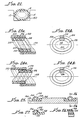
- Figures 2 through 7 show a number of canted coil assemblies 30, 32, 34, 36 suitable for use in the present invention, each including a plurality of coils 38, 40, 42, 44.
- the springs 30 and 32 have the coils 38, 40 interconnected in a manner forming a circular spring having a primary load-deflection characteristic along an axial direction of the circular spring 30, 32.
- Spring 30 shown in Figures 2 and 3 has a clockwise canting coil, with the windings 38 interconnected so that a back angle 48, which defines a trailing portion 50, is along an inside diameter 52 of the spring 30 and a front angle 56, which defines a leading portion 58 of the coil 30, is along an outside diameter 60 of the spring 30.
- the axial spring 32 therein has windings 40 interconnected in a manner having a counter-clockwise canted coils with a back angle 64 defining a trailing portion 66 along an inside diameter 68 of the spring 32 and a front angle 70, defining a leading portion 72 along an outside diameter 74 of the spring 32.
- springs 34, 36 having a plurality of windings 42, 44 which are interconnected in a manner forming a circular spring having a primary load-deflection characteristic along a radial direction indicated by the arrows 76, 78, respectively.
- the windings are interconnected in a manner for providing a clockwise canting with a back angle 82 defining a trailing portion 84 along a top 86 and a front angle 88 defining a leading portion 92 disposed along the bottom 100 of the spring 34.
- spring 36 may have windings 44 connected in a manner causing a canting of the coil in a counter-clockwise direction with a back angle 98 defining a trailing portion 100 along a bottom 102 of the spring 36 and a front angle 106 defining a leading portion 108 along a top 110 of the spring 36.
- all of the springs 30, 32, 34, 36 may have a generally constant force deflection characteristic within a working deflection thereof.
- Figure 7a shows in schematic form, a cross-section of the canted coil spring 34, in accordance with the present invention, with a turn angle of ⁇ , a measured coil width of C.W, a measured coil height of CH and a measured spring height H of the spring 34.
- the turn angle may be clockwise (bold lines) or counterclockwise. (Dashed lines).
- the turn angle ⁇ may be defined as an angle formed by a generally circular spring forming a cone or inverted cone, depending on the position of the spring, and measuring the turn angle for the horizontal to the intersection through the centerline 112 of the spring 34.
- Figure 8 shows a representative load-deflection curve A for springs 30, 32, 34, 36 in which the spring exhibits a generally linear load-deflection relationship as shown by the line segment 124, until it reaches a minimum load point 126, after which the load-deflection curve remains relatively constant within a working deflection 130 between the minimum load point 126 and a maximum load point 132. Between the minimum load point 126 and the maximum load point 132, the load-deflection curve may be constant, or show a slight increase as shown in Figure 8.
- the area between the minimum load point 126 and the maximum load point 132 is commonly referred to as the working range 130 of the spring.
- the spring 30, 32, 34, 36 is normally loaded for operation within this range as indicated by the point 134.
- the elastomer, or elastic material, 18a, 18b, may be any synthetic or natural material capable of recovering its original size and shape after deformation. That is, the material is resilient.
- the spring assembly 10 shown in Figure 1 has a generally circular shape, it should be appreciated that any irregular shape such as the spring assembly 150 shown in Figure 9 as long as the cross-section thereof is hollow in cross-section.
- the spring 12 may not be joined, for example, as shown in Figure 1.
- the length of elastomer coasted, or filled, windings may be used in applications suitable for linear springs.
- the spring 14 may be filled by any manufacturing method suitable for the elastomer employed, such methods including extrusion, molding, spraying or any other suitable method for introducing elastomer 18 in and around the windings 12 of the spring 14, while leaving a hollow cross section 20 along the centerline 16.
- Such other methods may include the fusing of two tubular parts (not shown), one disposed on the inside of the spring 14 and one disposed on the outside of the spring 14 with the fusing of the parts filling of the spaces between the windings 12.
- the elastomer 18 may be formed in and around the windings 12 while a rod 151 of fugative compound 150 is disposed within the windings 12. (See Figure 1C). Thereafter the fugative compound is dissipated or removed by heat or solution, as is well known in the art.
- FIG. 10 Various embodiments of the present invention are shown in Figures 10 through 15.
- windings 152 with an interior elastomer 154 are shown with the windings 152 having an elliptical shape and the elastomer 154 having a circular shaped void 156 therethrough.
- Figure 11 shows elliptically shaped windings 156 having an elastomer 158 with an offset, or generally rectangular, hollowed cross-sectional opening 160 therethrough
- Figure 12 shows an elliptically shaped windings 162 having an elastomer 164 with an irregularly shaped opening 166 comprising to generally circular cross-sectional areas 168, 168'.
- the elastic material may be disposed within the windings 152, 156, 162 as shown in Figures 10, 11 and 12 or, alternatively, as shown in Figure 13, an elastomer 168A may be disposed on one side 170A of windings 172A.
- This embodiment is most useful in applications in which a greater distribution of the load is desirable on the one side 170A of the windings 172A.
- inventions 170, 172, 174, of the present invention shown respectively in Figures 14 through 16, said embodiments 171, 172, 174 including windings 178, 180, 182 and elastomers 186, 188, 190.
- the embodiment 170 includes an open area 190 through the windings 178 in order to facilitate the passage of fluid (not shown) for pressure variation, cooling or lubrication purposes.
- the elastomer 188 may be disposed as a coating both the inside 194 and outside 196 of the winding 180, while Figure 16 shows the elastomer 190 disposed along the outside and through the windings 182. All of these embodiments differently affect the force-deflection characteristics of the embodiments 171, 172, 174 depending upon the application of the embodiment 171, 172, 174.
- the ability to maintain a relatively constant force within a certain deflection is affected by a number of parameters, all of which are taken into consideration, which include the cross-section of the elastomer and the disposition thereon as indicated in Figures 10 through 16, the thickness of the elastomer, the flexibility of the elastomer, the degree of bonding between the windings 152, 154, 170, 186, 188, 190 and corresponding elastomers 154, 156, 168, 186, 188, 190, the spacing between the windings 152, 154, 170, 178, 180, 182, the wire diameter, coil height and coil width, among other considerations.
- the ability of the hollowed canted-coil spring filled with an elastomer having a hollow center to achieve a high degree of deflection and maintain a relatively constant load within a high deflection decreases the total amount of force that is needed to affect sealing and this offers a significant advantage, especially in dynamic situations.
- the ability of the hollowed elastomer filled spring to stretch facilitates its assembly in a single groove construction, similar to that as can be found in O-ring applications for both mounting the assembly 10 in a piston (not shown) or in a housing (not shown).
- elastomer-filled spring 14 with hollow cross section 20 Another very important feature of the elastomer-filled spring 14 with hollow cross section 20 is its use as a seal itself.
- elastomers have used the canted-coil spring as a loading means in order to maintain intimate contact between the sealing surfaces of the elastomer.
- the elastomer tends to age or relax due to aging stiffness of the elastomer, or due to temperature cycling, and the spring is used to force the elastomer in contact with the sealing surfaces.
- both items can be accomplished in one, with a higher degree of reliability and sealing ability, and this can be done in reciprocating, rotating, oscillating, and static applications.
- Another important feature is to use the spring assembly 10 as a loading means to provide more uniform loading on a sealing surface (not shown) which results in substantially better performance because it enables the use of a smaller wire thus uniformly distributing the load which results in more effective sealing ability and longer seal life.
- the elastomer 18 may be any type of elastomeric material such as silicone, Buna N, nitrile, fluorosilicones, PTFE, elastomers, etc. Also, certain types of plastics that have the properties of elastomers can be used due to their high coefficient of friction, their operating temperature, etc.
- FIG. 17 A specific example of the force-deflection characteristics for the spring 14, with windings 12 is set forth in Figure 17, is shown in Figure 18 as curve A.
- an elastomer such as Dow Corning Silastic 732 RTV was filled between the windings 12 and interior thereof to a thickness of 0.016 inches with a cross-section as shown in Figure 10
- the resulting force-deflection curve obtained is illustrated as curve B in Figure 18.
- the same elastomer was disposed between the windings 12 and within the windings 12 to a thickness of 0.026 inches with a cross-section shown in Figure 12.
- the resulting force-deflection curve is shown as curve C in Figure 18.
- the force-deflection curve of the spring assemblies 152, 160 which remains relatively constant but greater than the spring without elastomer shown in Curve A.
- the amount of elastomer is increased or as a cross-section is varied by adding elastomer on the outside diameter or on the inside diameter of the coil, the force developed increases.
- FIG. 19a there is shown as spring assembly 200 in accordance with the present invention in which the spring 202, shown also in Figures 19b and c, includes a plurality of windings 204 which are preloaded before being imbedded in an elastomer 206.
- Curve A in Figure 20 shows the force-deflection curve for the spring 202 only while Curve B shows the load-deflection curve for the preloaded spring and an elastomer, the elastomer being Silastic 732 RTV adhesive sealant available for Dow Corning of Midland, Michigan.
- Curves D and E springs 30, 32, 34 36 having a solid elastomer cross-section with the elastomer not bonded to the windings 38, 40, 42, 44 (Curve E) and a hollow elastomer with the elastomer bonded to the windings 38, 40, 42, 44 (Curve D).
- the spring (Curve A) only has the lowest force and the spring with the hollow elastomer, which is primed and bonded, providing the highest load (Curve D).
- the spring having a solid elastomer provides a force curve slope increasing at a steeper angle. Such slope will vary depending on the hardness and flexibility of the elastomeric material. In the case of a very flexible material, the curve may have less slope but in the case of a bonded elastomeric material with a high durometer reading, the curve will be nearly proportional to deflection.
- Figure 21a shows a radial spring 210 filled with an elastomer material 212 having a hollow center 214.
- the spring is in a free position when filled with material. It should be contrasted with the Figure 21b in which the spring 210 is stretched, with greater spaces as indicated by the arrow 220 between the windings 210 when filled with the elastomer material 218, the latter having a hollow core 214 as shown in Figure 21C.
- the force developed by the spring 210 depends on the amount of stretch with the mechanical of the elastomer, degree of bonding, spacing between the coils, ratio of the coil height to coil width, etc.
- a spring of this type may be used in order to provide an extension load or can be used to provide a combination of extension load and compression load. In either case, stretching of the coil can be used to further modify the force-deflection curve of the spring 210.
- the spring 14 may be made longer than necessary to complete a circle within a groove 250 as shown in Figure 22, the groove 250 being in a piston or housing, not shown. In this instance, the excessive spring length will cause the elastomer 18 to butt and therefore eliminate any gap between the spring ends.
- FIG. 23a and b there is an alternate embodiment of the spring assembly 300 which includes a first plurality of windings 302 interconnected with another in a spaced-apart relationship for causing the spring assembly 300 to exert a generally constant force in a loading direction normal to a tangent to a centerline 304.
- an elastic material 306 is disposed around and between the plurality of windings 302 a hollow cross section 308 which provides means for modifying the force exerted by the spring 302 assembly 300 in response to deflection of the spring assembly 300 along a loading direction as hereinbefore described.
- a second plurality of windings 310 interconnected with one another in a spaced apart relationship and disposed in a cooperating relationship inside the first plurality of windings forcausing the spring assembly 300 to exert a generally constant force in a loading direction approximately normal to the centerline 304.
- Figure 23b shows a cross sectional view of the spring assembly 300 and also showing that the elastic materials 306, 312 may be separate from one another with a gap 320 therebetween to allow relative movement therebetween as the spring assembly 300 is loaded.
- a spring assembly 330 shown in Figures 24a and b include a first plurality of windings 332 with an elastic material 334 disposed therearound and a second plurality of windings 336 within the elastic material 338 therearound.
- the configuration of the first and second plurality of windings 332, 336 and elastic material 334, 338 is similar to the coil assembly 300 shown in Figure 23a and b except that the first plurality of windings 332is canted in an opposite direction from the second plurality of windings 336 along a centerline 342.
- the performance of the embodiments shown in Figures 23a and b and 24a and b are similar to that hereinbefore described in connection with the spring assembly 10 further extending the design range capability of the forced deflection curves thereof.
- FIGS 25-27 there is shown alternative embodiments 350, 352 of the present invention which include a plurality of windings 354, 356 within the elastic material 358, 360 thereabout.
- the feature of the embodiments of 350, 352 is the shape of the elastic 358, 360 which includes depending portions 364, 366 and 368, respectively, which provide a means for positioning the plurality of windings 354, 356 in order that the loading direction is approximately perpendicular to the centerline 370, 372, respectively.
- the elastomer 358 may be disposed between the windigs 354 as hereinabove shown in figures 19a, 23a and 24a.
Abstract
Description
Claims (16)
- A spring assembly (10, 10a) including at least one coil (14) comprising a plurality of windings (12, 12a) interconnected with one another in a spaced apart relationship and an elastic material (18, 18a) disposed around and between the windings (12, 12a), wherein the windings (12, 12a) are interconnected with one another in a manner causing the coil (14) to exert, within a working deflection, a slowly increasing force in a loading direction approximately normal to a tangent to a centerline of the coil (14), characterized in that adherence of the elastic material (18, 18a) to the windings (12, 12a) is a partial adherence, thereby determining the rate of increase or decrease of the exerted force in response to deflection of the coil (14), said elastic material (18, 18a) being disposed such that the spring assembly (10, 10a) retains a hollow cross-section along said centerline.
- A spring assembly (10, 10a) including at least one coil (14) comprising a plurality of windings (12, 12a) interconnected with one another in a spaced apart relationship and an elastic material (18, 18a) disposed around and between the windings (12, 12a), wherein the windings (12, 12a) are interconnected with one another in a manner causing the coil (14) to exert, within a working deflection, a slowly increasing force in a loading direction approximately normal to a tangent to a centerline of the coil (14), characterized in that the elastic material (18, 18a) does not adhere to the windings (12, 12a), thereby determining the rate of increase or decrease of the exerted force in response to deflection of the coil (14).
- The spring assembly according to claim 1 or 2 further characterized in that the windings (12, 12a) have an oval perimeter and the elastic material (154) includes a circular hollow center portion (156).
- The spring assembly according to claim 1 or 2 further characterized in that the windings (12, 12a) have an oval perimeter and the elastic material (164) includes a plurality of hollow areas (168, 168') inside of the plurality of windings (12, 12a).
- The spring assembly according to claim 1 or 2 further characterized in that the windings (12, 12a) have an oval perimeter and the elastic material (158) includes a generally rectilinear hollow center portion (160).
- The spring assembly according to claim 1 or 2 further characterized in that the elastic material (358) includes dependent portions (364, 366) substantially larger than a diameter of the windings (354).
- The spring assembly according to claim 1 or 2 further characterized in that the windings (12, 12a) are disposed within the elastic material (18, 18a) in a stretched apart relationship, the elastic material (18, 18a) having sufficient resistance to hold the windings (12, 12a) in the stretched spaced-apart relationship, the spacing between windings (12, 12a) in the stretched spaced-apart relationship being greater than a spacing between windings (12, 12a) when not held in the stretched apart relationship by the elastic material.
- The spring assembly according to claim 1 or 2, wherein the windings (12, 12a) are disposed within the elastic material (18, 18a) in a preloaded condition in which the windings (12, 12a) are deflected along the loading direction.
- The spring assembly according to claim 1 or 2 further characterized by a second coil having windings (310, 336) interconnected with one another in a spaced-apart relationship within a first coil windings (302, 332).
- The spring assembly according to claim 9 further characterized in that the elastic material (306, 312; 334, 338) includes an outer portion (306, 334) disposed around the first coil windings (302) and an inner portion (312, 338) disposed around the second coil windings (336), the outer portions (306, 334) and inner portions (312, 338) being separate and unattached to one another.
- The spring assembly according to claim 9 further characterized in that the first coil windings (302) are canted in the same direction as the second coil windings (310).
- The spring assembly according to claim 9 further characterized in that the first coil windings (302) are canted in an opposite direction as the second coil windings (310).
- A method for manufacturing of a spring assembly comprising:
fabricating a wire to produce a coil comprising windings interconnected with one another in a spaced-apart relationship, disposing an elastic material in and around said windings, characterized in that conditions between the elastic material and the windings are selected such that the elastic material does not adhere to said windings. - A method for manufacturing of a spring assembly comprising:
fabricating a wire to produce a coil comprising windings interconnected with one another in a spaced-apart relationship, disposing an elastic material in and around said windings, characterized in that conditions between the elastic material and the windings are selected such that only partial adherence of said elastic material to said windings results, and that the elastic material is disposed such that the spring assembly retains a hollow cross-section along its centerline. - The method according to claim 13 or 14 comprising the step of:
joining ends of said wire and said elastic material to form a continuous spring assembly. - The method according to claim 13 or 14 further comprising the steps of disposing a rod of fugative compound within the coil and elastic material and removing the rod of fugative compound to provide hollow portions within the elastic material.
Applications Claiming Priority (2)
| Application Number | Priority Date | Filing Date | Title |
|---|---|---|---|
| US07/572,242 US5203849A (en) | 1990-03-20 | 1990-08-27 | Canted coil spring in length filled with an elastomer |
| US572242 | 1990-08-27 |
Publications (3)
| Publication Number | Publication Date |
|---|---|
| EP0473085A2 EP0473085A2 (en) | 1992-03-04 |
| EP0473085A3 EP0473085A3 (en) | 1992-10-28 |
| EP0473085B1 true EP0473085B1 (en) | 1998-10-07 |
Family
ID=24286955
Family Applications (1)
| Application Number | Title | Priority Date | Filing Date |
|---|---|---|---|
| EP91114224A Expired - Lifetime EP0473085B1 (en) | 1990-08-27 | 1991-08-24 | Canted coil spring in length filled with an elastomer |
Country Status (5)
| Country | Link |
|---|---|
| US (1) | US5203849A (en) |
| EP (1) | EP0473085B1 (en) |
| JP (1) | JPH0617865A (en) |
| AT (1) | ATE172008T1 (en) |
| DE (1) | DE69130317T2 (en) |
Families Citing this family (52)
| Publication number | Priority date | Publication date | Assignee | Title |
|---|---|---|---|---|
| US5505466A (en) * | 1992-12-18 | 1996-04-09 | Dana Corporation | Cylinder head gasket with retaining ring and spring seal |
| US5338046A (en) * | 1992-12-18 | 1994-08-16 | Dana Corporation | Composite powdered metal retaining ring |
| US5474309A (en) * | 1993-06-11 | 1995-12-12 | Bal Seal Engineering Company, Inc. | Gasket assembly for sealing electromagnetic waves |
| US5411348A (en) * | 1993-10-26 | 1995-05-02 | Bal Seal Engineering Company, Inc. | Spring mechanism to connect, lock and unlock, members |
| US5545842A (en) * | 1993-10-26 | 1996-08-13 | Bal Seal Engineering Company, Inc. | Radially mounted spring to connect, lock and unlock, and for snap-on fastening, and for mechanical, electromagnetic shielding, electrical conductivity, and thermal dissipation with environmental sealing |
| US5984283A (en) * | 1996-03-29 | 1999-11-16 | Toyoda Gosei Co., Ltd. | Vibration-damping rubber in suspension of vehicle |
| EP0890758A3 (en) | 1997-07-07 | 2000-11-22 | Bal Seal Engineering Company, Inc. | Radial and axial springs with coils canting along the major axis |
| US6182859B1 (en) * | 1998-11-03 | 2001-02-06 | The Northwestern Corporation | Brush housing for bulk vending machine |
| GB2368100B (en) * | 2000-10-19 | 2004-02-18 | Rolls Royce Plc | Seal fitting |
| JP4671211B2 (en) * | 2001-02-28 | 2011-04-13 | Nok株式会社 | Damper ring mounting structure |
| EP1552182B1 (en) * | 2002-09-30 | 2006-12-20 | Bal Seal Engineering Co., Inc. | Canted coil springs various designs |
| US7731947B2 (en) | 2003-11-17 | 2010-06-08 | Intarcia Therapeutics, Inc. | Composition and dosage form comprising an interferon particle formulation and suspending vehicle |
| US11246913B2 (en) | 2005-02-03 | 2022-02-15 | Intarcia Therapeutics, Inc. | Suspension formulation comprising an insulinotropic peptide |
| WO2006083761A2 (en) | 2005-02-03 | 2006-08-10 | Alza Corporation | Solvent/polymer solutions as suspension vehicles |
| US7316593B2 (en) * | 2005-05-19 | 2008-01-08 | Bal Seal Engineering Co., Inc. | Electrical connector with embedded canted coil spring |
| MX2008014870A (en) | 2006-05-30 | 2009-02-12 | Intarcia Therapeutics Inc | Two-piece, internal-channel osmotic delivery system flow modulator. |
| ES2422864T3 (en) * | 2006-08-09 | 2013-09-16 | Intarcia Therapeutics, Inc | Osmotic release systems and piston units |
| WO2008022014A2 (en) * | 2006-08-10 | 2008-02-21 | Research Sciences, Llc | Multimember extended range compressible seal |
| WO2008133908A2 (en) | 2007-04-23 | 2008-11-06 | Intarcia Therapeutics, Inc. | Suspension formulations of insulinotropic peptides and uses thereof |
| GB0712779D0 (en) * | 2007-07-02 | 2007-08-08 | Edwards Ltd | Seal |
| EP2240155B1 (en) | 2008-02-13 | 2012-06-06 | Intarcia Therapeutics, Inc | Devices, formulations, and methods for delivery of multiple beneficial agents |
| US7837519B2 (en) * | 2009-02-24 | 2010-11-23 | Tyco Electronics Corporation | Electrical bushing with helper spring to apply force to contact spring |
| US7942682B2 (en) * | 2009-02-24 | 2011-05-17 | Tyco Electronics Corporation | Electrical connector with slider component for fault condition connection |
| US7942683B2 (en) * | 2009-02-24 | 2011-05-17 | Tyco Electronics Corporation | Electrical bushing with radial interposer spring |
| US20100289198A1 (en) * | 2009-04-28 | 2010-11-18 | Pete Balsells | Multilayered canted coil springs and associated methods |
| US8684362B2 (en) | 2009-08-12 | 2014-04-01 | Bal Seal Engineering, Inc. | Cartridge seal assemblies and associated methods |
| WO2011037623A1 (en) | 2009-09-28 | 2011-03-31 | Intarcia Therapeutics, Inc. | Rapid establishment and/or termination of substantial steady-state drug delivery |
| US9010740B2 (en) | 2010-10-21 | 2015-04-21 | Veloce Labs, LLC | Multi-canted coils, tubes, and structures |
| US20120208755A1 (en) | 2011-02-16 | 2012-08-16 | Intarcia Therapeutics, Inc. | Compositions, Devices and Methods of Use Thereof for the Treatment of Cancers |
| US8428724B2 (en) | 2011-03-11 | 2013-04-23 | Greatbatch Ltd. | Low insertion force electrical connector for implantable medical devices |
| WO2014043394A1 (en) | 2012-09-14 | 2014-03-20 | Bal Seal Engineering, Inc. | Connector housings, use of, and method therefor |
| US9518626B2 (en) * | 2012-11-13 | 2016-12-13 | Bal Seal Engineering, Inc. | Canted coil springs and assemblies and related methods |
| JP6062253B2 (en) * | 2013-01-15 | 2017-01-18 | Nok株式会社 | Anti-vibration bush |
| EP2971842B1 (en) | 2013-03-14 | 2019-07-10 | Bal Seal Engineering, Inc. | Canted coil spring with longitudinal component within and related methods |
| US10598241B2 (en) | 2014-02-26 | 2020-03-24 | Bal Seal Engineering, Inc. | Multi deflection canted coil springs and related methods |
| US10151368B2 (en) | 2014-05-02 | 2018-12-11 | Bal Seal Engineering, Inc. | Nested canted coil springs, applications thereof, and related methods |
| EP3195415B1 (en) | 2014-09-15 | 2023-12-27 | Bal Seal Engineering, LLC | Connector assembly and method of assembling the same |
| US9889085B1 (en) | 2014-09-30 | 2018-02-13 | Intarcia Therapeutics, Inc. | Therapeutic methods for the treatment of diabetes and related conditions for patients with high baseline HbA1c |
| CN113598842A (en) | 2015-06-03 | 2021-11-05 | 因塔西亚制药公司 | Implant placement and removal system |
| DE102015112283A1 (en) * | 2015-07-28 | 2017-02-02 | Otto Bock Healthcare Gmbh | Joint for an orthopedic device |
| US10487899B2 (en) | 2016-02-17 | 2019-11-26 | Nelson Products, Inc. | Canted coil spring shock absorber |
| EP3458084B1 (en) | 2016-05-16 | 2020-04-01 | Intarcia Therapeutics, Inc | Glucagon-receptor selective polypeptides and methods of use thereof |
| USD860451S1 (en) | 2016-06-02 | 2019-09-17 | Intarcia Therapeutics, Inc. | Implant removal tool |
| USD840030S1 (en) | 2016-06-02 | 2019-02-05 | Intarcia Therapeutics, Inc. | Implant placement guide |
| EP3565580B1 (en) | 2017-01-03 | 2024-03-06 | i2o Therapeutics, Inc. | Continuous administration of exenatide and co-adminstration of acetaminophen, ethinylestradiol or levonorgestrel |
| FR3068101B1 (en) | 2017-06-27 | 2020-06-19 | Centre Technique Des Industries Mecaniques | MULTI-LAYER SEAL |
| CN107255128A (en) * | 2017-07-28 | 2017-10-17 | 大族激光科技产业集团股份有限公司 | A kind of helical spring |
| US10900531B2 (en) | 2017-08-30 | 2021-01-26 | Bal Seal Engineering, Llc | Spring wire ends to faciliate welding |
| US11353079B2 (en) | 2017-10-05 | 2022-06-07 | Bal Seal Engineering, Llc | Spring assemblies, applications of spring assemblies, and related methods |
| CN111566376B (en) * | 2018-03-07 | 2022-03-29 | 中央发条株式会社 | Spring |
| USD933219S1 (en) | 2018-07-13 | 2021-10-12 | Intarcia Therapeutics, Inc. | Implant removal tool and assembly |
| US10995812B2 (en) | 2019-02-27 | 2021-05-04 | Nelson Products, Inc. | Canted coil spring shock absorber |
Family Cites Families (18)
| Publication number | Priority date | Publication date | Assignee | Title |
|---|---|---|---|---|
| GB623170A (en) * | 1947-04-24 | 1949-05-12 | Angus George Co Ltd | Improvements relating to endless toroidal wire springs and spring belts |
| BE527845A (en) * | 1953-06-19 | |||
| US2957717A (en) * | 1957-03-13 | 1960-10-25 | Cie De Pont A Mousson | Sealing members and reinforcements therefor |
| US3051500A (en) * | 1957-09-16 | 1962-08-28 | Sumner D Wiltse | O ring structure |
| FR1289608A (en) * | 1961-02-23 | 1962-04-06 | Cie De Pont A Mousson | Reinforcement for sealing gasket and gasket including application |
| BE668603A (en) * | 1964-08-20 | |||
| DE1234105B (en) * | 1964-10-30 | 1967-02-09 | Aeroquip Ag | U-shaped sleeve seal |
| US3406979A (en) * | 1965-02-19 | 1968-10-22 | California Fruit Concentrates | Reinforced o-ring |
| US3468527A (en) * | 1968-03-08 | 1969-09-23 | North American Rockwell | Coil spring |
| US3653670A (en) * | 1970-05-11 | 1972-04-04 | Cascade Corp | Spring-loaded seal with symmetrical cross section |
| US3813105A (en) * | 1972-04-03 | 1974-05-28 | M Mcqueen | Seal |
| DE2427748A1 (en) * | 1974-02-14 | 1975-08-21 | Sperry Rand Corp | RING-CAPSULATED CUFF SHAFT SEAL |
| US4379558A (en) * | 1981-05-01 | 1983-04-12 | Utex Industries, Inc. | Anti-extrusion packing member |
| US4509763A (en) * | 1983-05-02 | 1985-04-09 | The Gates Rubber Company | Radially extensible joint packing with helical spring support means |
| US4655462A (en) * | 1985-01-07 | 1987-04-07 | Peter J. Balsells | Canted coiled spring and seal |
| US4640500A (en) * | 1985-10-31 | 1987-02-03 | Shiau Jgi J | Inherently effectively damped coiled spring |
| US4809989A (en) * | 1987-06-05 | 1989-03-07 | Otis Engineering Corporation | Coil spring supported sealing element and device |
| US5160122A (en) * | 1990-03-20 | 1992-11-03 | Peter J. Balsells | Coil spring with an elastomer having a hollow coil cross section |
-
1990
- 1990-08-27 US US07/572,242 patent/US5203849A/en not_active Expired - Lifetime
-
1991
- 1991-08-24 EP EP91114224A patent/EP0473085B1/en not_active Expired - Lifetime
- 1991-08-24 DE DE69130317T patent/DE69130317T2/en not_active Expired - Fee Related
- 1991-08-24 AT AT91114224T patent/ATE172008T1/en not_active IP Right Cessation
- 1991-08-27 JP JP3215585A patent/JPH0617865A/en active Pending
Also Published As
| Publication number | Publication date |
|---|---|
| DE69130317T2 (en) | 1999-06-17 |
| US5203849A (en) | 1993-04-20 |
| DE69130317D1 (en) | 1998-11-12 |
| EP0473085A3 (en) | 1992-10-28 |
| ATE172008T1 (en) | 1998-10-15 |
| JPH0617865A (en) | 1994-01-25 |
| EP0473085A2 (en) | 1992-03-04 |
Similar Documents
| Publication | Publication Date | Title |
|---|---|---|
| EP0473085B1 (en) | Canted coil spring in length filled with an elastomer | |
| EP0450392B1 (en) | Coil spring with an elastomer having a hollow coil cross section | |
| US5161806A (en) | Spring-loaded, hollow, elliptical ring seal | |
| EP0490204B1 (en) | Seal with spring energizer and method | |
| US5239737A (en) | Method for manufacturing a spring assembly | |
| US4961253A (en) | Manufacturing method for canted-coil spring with turn angle and seal | |
| US5108078A (en) | Canted-coil spring loaded while in a cavity | |
| US4964204A (en) | Method for making a garter-type axially-resilient coil spring | |
| EP0768735B1 (en) | Gasket for sealing electromagnetic waves filled with a conductive material | |
| US4915366A (en) | Outside back angle canted coil spring | |
| US4974821A (en) | Canted-coil spring with major axis radial loading | |
| EP0339544B1 (en) | Garter spring with canted back angle located on outside diameter | |
| US4599784A (en) | Method of assembling flexible conduit and fitting | |
| US2906552A (en) | Sealing and bearing device having low friction sealing faces | |
| US6161838A (en) | Cartridge seal stack | |
| US4379558A (en) | Anti-extrusion packing member | |
| US7116026B2 (en) | Adhesion structure for motor, having thickness determining means | |
| EP0339542A2 (en) | Axially resilient, canted-coil spring with turn angle and seal | |
| GB2169378A (en) | Coiled spring and coiled spring seal | |
| JP2011506866A (en) | High pressure dynamic and static equipment seal assemblies | |
| US20070052180A1 (en) | Sealing device for reciprocating shaft | |
| US6988733B2 (en) | Bonded PTFE radial shaft seal | |
| JP3695469B2 (en) | Sealing device | |
| GB2095345A (en) | Compound bearing | |
| EP0491258B1 (en) | Spring-loaded ring seal assembly |
Legal Events
| Date | Code | Title | Description |
|---|---|---|---|
| PUAI | Public reference made under article 153(3) epc to a published international application that has entered the european phase |
Free format text: ORIGINAL CODE: 0009012 |
|
| AK | Designated contracting states |
Kind code of ref document: A2 Designated state(s): AT BE CH DE DK ES FR GB GR IT LI LU NL SE |
|
| PUAL | Search report despatched |
Free format text: ORIGINAL CODE: 0009013 |
|
| AK | Designated contracting states |
Kind code of ref document: A3 Designated state(s): AT BE CH DE DK ES FR GB GR IT LI LU NL SE |
|
| 17P | Request for examination filed |
Effective date: 19921231 |
|
| 17Q | First examination report despatched |
Effective date: 19950403 |
|
| GRAG | Despatch of communication of intention to grant |
Free format text: ORIGINAL CODE: EPIDOS AGRA |
|
| GRAG | Despatch of communication of intention to grant |
Free format text: ORIGINAL CODE: EPIDOS AGRA |
|
| GRAH | Despatch of communication of intention to grant a patent |
Free format text: ORIGINAL CODE: EPIDOS IGRA |
|
| GRAH | Despatch of communication of intention to grant a patent |
Free format text: ORIGINAL CODE: EPIDOS IGRA |
|
| GRAA | (expected) grant |
Free format text: ORIGINAL CODE: 0009210 |
|
| AK | Designated contracting states |
Kind code of ref document: B1 Designated state(s): AT BE CH DE DK ES FR GB GR IT LI LU NL SE |
|
| PG25 | Lapsed in a contracting state [announced via postgrant information from national office to epo] |
Ref country code: IT Free format text: LAPSE BECAUSE OF FAILURE TO SUBMIT A TRANSLATION OF THE DESCRIPTION OR TO PAY THE FEE WITHIN THE PRE;WARNING: LAPSES OF ITALIAN PATENTS WITH EFFECTIVE DATE BEFORE 2007 MAY HAVE OCCURRED AT ANY TIME BEFORE 2007. THE CORRECT EFFECTIVE DATE MAY BE DIFFERENT FROM THE ONE RECORDED.SCRIBED TIME-LIMIT Effective date: 19981007 Ref country code: GR Free format text: LAPSE BECAUSE OF NON-PAYMENT OF DUE FEES Effective date: 19981007 Ref country code: ES Free format text: THE PATENT HAS BEEN ANNULLED BY A DECISION OF A NATIONAL AUTHORITY Effective date: 19981007 Ref country code: FR Free format text: LAPSE BECAUSE OF FAILURE TO SUBMIT A TRANSLATION OF THE DESCRIPTION OR TO PAY THE FEE WITHIN THE PRESCRIBED TIME-LIMIT Effective date: 19981007 Ref country code: BE Free format text: LAPSE BECAUSE OF FAILURE TO SUBMIT A TRANSLATION OF THE DESCRIPTION OR TO PAY THE FEE WITHIN THE PRESCRIBED TIME-LIMIT Effective date: 19981007 Ref country code: CH Free format text: LAPSE BECAUSE OF FAILURE TO SUBMIT A TRANSLATION OF THE DESCRIPTION OR TO PAY THE FEE WITHIN THE PRESCRIBED TIME-LIMIT Effective date: 19981007 Ref country code: AT Free format text: LAPSE BECAUSE OF FAILURE TO SUBMIT A TRANSLATION OF THE DESCRIPTION OR TO PAY THE FEE WITHIN THE PRESCRIBED TIME-LIMIT Effective date: 19981007 Ref country code: NL Free format text: LAPSE BECAUSE OF FAILURE TO SUBMIT A TRANSLATION OF THE DESCRIPTION OR TO PAY THE FEE WITHIN THE PRESCRIBED TIME-LIMIT Effective date: 19981007 Ref country code: LI Free format text: LAPSE BECAUSE OF FAILURE TO SUBMIT A TRANSLATION OF THE DESCRIPTION OR TO PAY THE FEE WITHIN THE PRESCRIBED TIME-LIMIT Effective date: 19981007 |
|
| REF | Corresponds to: |
Ref document number: 172008 Country of ref document: AT Date of ref document: 19981015 Kind code of ref document: T |
|
| REG | Reference to a national code |
Ref country code: CH Ref legal event code: EP |
|
| REF | Corresponds to: |
Ref document number: 69130317 Country of ref document: DE Date of ref document: 19981112 |
|
| PG25 | Lapsed in a contracting state [announced via postgrant information from national office to epo] |
Ref country code: DK Free format text: LAPSE BECAUSE OF FAILURE TO SUBMIT A TRANSLATION OF THE DESCRIPTION OR TO PAY THE FEE WITHIN THE PRESCRIBED TIME-LIMIT Effective date: 19990107 Ref country code: SE Free format text: LAPSE BECAUSE OF FAILURE TO SUBMIT A TRANSLATION OF THE DESCRIPTION OR TO PAY THE FEE WITHIN THE PRESCRIBED TIME-LIMIT Effective date: 19990107 |
|
| NLV1 | Nl: lapsed or annulled due to failure to fulfill the requirements of art. 29p and 29m of the patents act | ||
| EN | Fr: translation not filed | ||
| REG | Reference to a national code |
Ref country code: CH Ref legal event code: PL |
|
| PLBE | No opposition filed within time limit |
Free format text: ORIGINAL CODE: 0009261 |
|
| STAA | Information on the status of an ep patent application or granted ep patent |
Free format text: STATUS: NO OPPOSITION FILED WITHIN TIME LIMIT |
|
| PG25 | Lapsed in a contracting state [announced via postgrant information from national office to epo] |
Ref country code: LU Free format text: LAPSE BECAUSE OF NON-PAYMENT OF DUE FEES Effective date: 19990824 |
|
| 26N | No opposition filed | ||
| REG | Reference to a national code |
Ref country code: GB Ref legal event code: IF02 |
|
| PGFP | Annual fee paid to national office [announced via postgrant information from national office to epo] |
Ref country code: GB Payment date: 20050817 Year of fee payment: 15 |
|
| PGFP | Annual fee paid to national office [announced via postgrant information from national office to epo] |
Ref country code: DE Payment date: 20050930 Year of fee payment: 15 |
|
| PG25 | Lapsed in a contracting state [announced via postgrant information from national office to epo] |
Ref country code: DE Free format text: LAPSE BECAUSE OF NON-PAYMENT OF DUE FEES Effective date: 20070301 |
|
| GBPC | Gb: european patent ceased through non-payment of renewal fee |
Effective date: 20060824 |
|
| PG25 | Lapsed in a contracting state [announced via postgrant information from national office to epo] |
Ref country code: GB Free format text: LAPSE BECAUSE OF NON-PAYMENT OF DUE FEES Effective date: 20060824 |