EP0472002A1 - Pipe section with connecting elements - Google Patents
Pipe section with connecting elements Download PDFInfo
- Publication number
- EP0472002A1 EP0472002A1 EP91112563A EP91112563A EP0472002A1 EP 0472002 A1 EP0472002 A1 EP 0472002A1 EP 91112563 A EP91112563 A EP 91112563A EP 91112563 A EP91112563 A EP 91112563A EP 0472002 A1 EP0472002 A1 EP 0472002A1
- Authority
- EP
- European Patent Office
- Prior art keywords
- pipe
- recesses
- projections
- sleeve
- pipe part
- Prior art date
- Legal status (The legal status is an assumption and is not a legal conclusion. Google has not performed a legal analysis and makes no representation as to the accuracy of the status listed.)
- Granted
Links
Images

Classifications
-
- F—MECHANICAL ENGINEERING; LIGHTING; HEATING; WEAPONS; BLASTING
- F16—ENGINEERING ELEMENTS AND UNITS; GENERAL MEASURES FOR PRODUCING AND MAINTAINING EFFECTIVE FUNCTIONING OF MACHINES OR INSTALLATIONS; THERMAL INSULATION IN GENERAL
- F16L—PIPES; JOINTS OR FITTINGS FOR PIPES; SUPPORTS FOR PIPES, CABLES OR PROTECTIVE TUBING; MEANS FOR THERMAL INSULATION IN GENERAL
- F16L37/00—Couplings of the quick-acting type
- F16L37/08—Couplings of the quick-acting type in which the connection between abutting or axially overlapping ends is maintained by locking members
- F16L37/084—Couplings of the quick-acting type in which the connection between abutting or axially overlapping ends is maintained by locking members combined with automatic locking
Definitions
- the invention relates to a pipe part with connecting elements arranged at the ends for tensile, releasable connection of the pipe part to corresponding further pipe parts.
- Such pipe parts are used in many technical areas. Their mutual connection is conventionally carried out by means of union nuts which are screwed onto a threaded part at one end of the tube part.
- Such connection systems are necessarily made up of several parts.
- a tool is usually required to connect or disconnect two pipe parts. Both are undesirable because they make production and assembly more expensive. Plug connections have also become known, but which either do not ensure a tensile connection or are then no longer detachable.
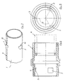
- FIGS. 1 and 2 each show the ends of two pipe parts 1, 1 'that come into connection. However, they also represent the two different ends of a single tube part.
- each of the tube parts 1, 1 ' has a sleeve 2 at one end.
- the sleeve 2 has a plurality of projections 3 on its inner circumference on the plug side, which point inwards protrude.
- an O-ring 4 connects to it as a seal.
- each tube part is essentially merely provided with recesses 5 which are arranged on the tube outer surface in accordance with the projections 4.
- the sleeve 2 is preferably designed as a plastic injection-molded part and firmly connected to a pipe section 6, which is produced in any length per se by extrusion from plastic. As can be seen in particular from FIGS. 1 and 2, the sleeve is not butt-welded to the tube piece 6, but rather encompasses it up to a stop 8. The welding takes place on the flanks which abut one another. This means there is no internal welding burr, which results in a smooth inner tube surface.
- connection area is essentially smooth and without projections (see FIG. 2), which facilitates the drawing in and / or blowing of lines into the protective pipe.
- connection between the pipe parts 1, 1 ' is to be released, one of the pipe parts must be rotated slightly about its axis, as indicated by the arrow in FIG. 2.
- a certain amount of rotational resistance has to be overcome in order to lift the projections 3 out of the recesses onto the adjacent tube circumference. This is a safeguard against unintentional loosening of the connection.
- the projections 3 or recesses 5 are Dimensioned so that a rotation through an angle of less than 30 ° is sufficient for loosening. Thanks to the elasticity of the plastic, this is also possible by hand, even when pipes are installed.
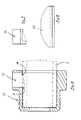
- FIGS. 3 to 5 from which the arrangement of the projections 3 and the recesses 5 results in detail.
- three recesses 5 or protrusions 3 are arranged on the circumference at angular intervals of 120.
- the recesses 5 are formed as incisions on the pipe outer surface, which form axial stops 10 against the associated pipe end. In the pipe circumferential direction, however, they pass continuously into the pipe outer surface, so that the projections 5 slide out of the incisions in the circumferential direction when a pipe part rotates, and the pipe parts can then be pulled apart.
- guides 12 are formed for a tool 13 for the mechanical removal of pipe material. This is shown in FIG. 7 in front view and in FIG. 8 in side view.
- the guides 12 run essentially tangentially to the tube circumference, so that the knife 13 is guided tangentially therein.
- a stop 14 is provided in the guides 12, which ensures the correct depth of the recess 5. In this way, the recesses 5 can be made at the right place on the construction site in a very short time so that the end of the pipe part can interact with the sleeve of a pipe part to be connected in the manner already described.
- the pipe parts 1, 1 engage in one another in the connected state without longitudinal play. It may now be desirable to design the connection so that it is able to accommodate tube dilation.
- the sleeve 2 can be made a little longer as a variant, so that the sleeve-free pipe end 1 can shift somewhat into the sleeve without the tensile connection being released.
- a preferred application of the pipe parts described is their use as protective pipes for transmission lines or power supply, which are laid underground. The same system can also be used for unpressurized sewage systems and for pressure lines (water supply) as well as for general line construction.
Abstract
Description
Die Erfindung betrifft einen Rohrteil mit endseitig angeordneten Verbindungsorganen zum zugfesten, lösbaren Verbinden des Rohrteils mit entsprechenden, weiteren Rohrteilen. Solche Rohrteile finden in vielen technischen Bereichen Verwendung. Ihre gegenseitige Verbindung erfolgt herkömmlicherweise mittels Ueberwurfmuttern, die auf einen Gewindeteil an einem Ende des Rohrteils aufgeschraubt werden. Solche Verbindungssysteme sind erzwungenermassen mehrteilig. Zudem wird zum Verbinden bzw. Lösen zweier Rohrteile in aller Regel ein Werkzeug benötigt. Beides ist unerwünscht, weil sich Herstellung und Montage damit verteuern. Es sind auch schon Steckverbindungen bekannt geworden, welche aber entweder keine zugfeste Verbindung sicherstellen oder dann nicht mehr lösbar sind. Ferner ist es bei herkömmlichen Verbindungen oft nicht möglich, die Rohrteile auf der Baustelle abzulängen, weil damit einerends die Verbindungsorgane wegfallen.The invention relates to a pipe part with connecting elements arranged at the ends for tensile, releasable connection of the pipe part to corresponding further pipe parts. Such pipe parts are used in many technical areas. Their mutual connection is conventionally carried out by means of union nuts which are screwed onto a threaded part at one end of the tube part. Such connection systems are necessarily made up of several parts. In addition, a tool is usually required to connect or disconnect two pipe parts. Both are undesirable because they make production and assembly more expensive. Plug connections have also become known, but which either do not ensure a tensile connection or are then no longer detachable. Furthermore, it is often not possible with conventional connections to cut the pipe parts to length on the construction site because the connecting members are thus eliminated at one end.
Für verschiedene Anwendungen, aber insbesondere für Schutzrohre zum Einziehen elektrischer oder Lichtleiter-Kabel, ist es indessen erwünscht, einstückige Rohrteile ohne zusätzliche Bauteile zugfest und lösbar miteinander verbinden zu können, wobei die Rohrteile je nach Bedarf ablängbar sein sollen.For various applications, but in particular for protective tubes for pulling in electrical or optical fiber cables, it is, however, desirable to be able to connect one-piece tube parts to one another in a tensile and detachable manner without additional components, the tube parts being able to be cut to length as required.
Die Lösung dieser Aufgabe wird durch die in den Ansprüchen definierten Merkmale erreicht. Damit wird eine einfach zu handhabende Steckverbindung geschaffen, welche nach dem Einrasten zugfest ist. Zum Lösen werden benachbarte Rohrteile geringfügig gegeneinander verdreht, wonach sie auseinander gezogen werden können. Dabei weisen die Schutzrohrteile keine beweglichen Elemente auf, sondern sind - bis auf allfällige Dichtungen - einstückig ausgebildet, was ihre Lagerhaltung und Montage wesentlich vereinfacht. Soll ein Rohrstück abgelängt werden, so lassen sich am Ende des abgelängten Rohrstücks die Verbindungsorgane als einfache Ausnehmungen in der Rohroberfläche anbringen.This object is achieved by the features defined in the claims. This creates an easy-to-use plug-in connection, which is tensile after snapping. To loosen them, adjacent pipe parts are slightly turned against each other, after which they can be pulled apart. The protective tube parts do not have any movable elements, but - apart from any seals - are made in one piece, which considerably simplifies their storage and assembly. If a pipe section is to be cut to length, the connecting members can be made as simple recesses in the pipe surface at the end of the cut pipe section.
Anhand der beiliegenden Zeichnungen soll dies im einzelnen an einem Ausführungsbeispiel näher erläutert werden. Es zeigen:
Figur 1 zwei Rohrstücke mit ihren entgegengesetzten Enden vor der Erstellung der Verbindung, in geschnittener Darstellung;Figur 2 eine entsprechende Darstellung nach dem Zusammenfügen;Figur 3 das mit Ausnehmungen versehene Rohrende, in perspektivischer Ansicht;Figur 4 das mit einer Muffe versehene Rohrende, in Schnittansicht;Figur 5 eine achsiale Aufsicht auf das mit einer Muffe versehene Rohrende;Figur 6 eine Lehre zum Anbringen der Ausnehmungen am Rohrende, in Schnittansicht;Figur 7 eine Frontansicht eines Werkzeuges, das mit der Lehre vonFigur 6 zusammenwirkt, undFigur 8 eine Seitenansicht dieses Werkzeugs.
- Figure 1 shows two pipe pieces with their opposite ends before creating the connection, in a sectional view;
- Figure 2 shows a corresponding representation after the assembly;
- Figure 3 shows the pipe end provided with recesses, in a perspective view;
- 4 shows the pipe end provided with a sleeve, in a sectional view;
- Figure 5 is an axial plan view of the pipe end provided with a sleeve;
- FIG. 6 shows a teaching for making the recesses at the pipe end, in a sectional view;
- Figure 7 is a front view of a tool which interacts with the teaching of Figure 6, and
- Figure 8 is a side view of this tool.
In den Figuren 1 und 2 sind jeweils die zur Verbindung gelangenden Enden zweier Rohrteile 1,1' gezeigt. Sie stellen aber ebenso die beiden unterschiedlichen Enden eines einzigen Rohrteils dar. Wie sich daraus ersehen lässt, besitzt jeder der Rohrteile 1,1' an seinem einen Ende eine Muffe 2. Die Muffe 2 besitzt an ihrem Innenumfang steckseitig mehrere Vorsprünge 3, die nach innen ragen. Rohrseitig schliesst daran ein O-Ring 4 als Dichtung an. An seinem anderen Ende ist jeder Rohrteil im wesentlichen bloss mit Ausnehmungen 5 versehen, die an der Rohraussenfläche entsprechend den Vorsprüngen 4 angeordnet sind.FIGS. 1 and 2 each show the ends of two
Die Muffe 2 ist vorzugsweise als Kunststoffspritzteil ausgebildet und fest mit einem Rohrstück 6 verbunden, das in an sich beliebige Länge durch Extrusion aus Kunststoff hergestellt wird. Die Muffe ist, wie sich insbesondere aus den Figuren 1 und 2 ergibt, nicht stumpf mit dem Rohrstück 6 verschweisst, sondern umfasst dieses bis zu einem Anschlag 8. Die Verschweissung erfolgt an den aneinander anliegenden Flanken. Es entsteht damit kein innenliegender Schweissgrat, womit eine glatte Rohrinnenfläche erzielt wird.The
Zur gegenseitigen Verbindung werden zwei Rohrteile 1,1' mit gegeneinander ausgerichteten Verbindungsorganen 3, 5 ineinander geschoben, wofür an der Rohraussenseite Markierungen 7 (vergl. Figur 3) vorgesehen sind. Dazu wird das muffenlose Rohrende in die Muffe 2 eingeführt (vergl. Figur 2). Durch elastische Dehnung bzw. Stauchung der Rohrteile 1,1', gleiten die Vorspünge 3, die zu diesem Zweck mit Auflaufschräge 15 versehene Nasen bilden (Fig. 4), über die Aussenfläche des muffenlosen Endes und rasten elastisch in die Ausnehmungen 5 ein.For mutual connection, two
Damit ergibt sich eine längskraftschlüssige Verbindung zwischen den Rohrteilen 1,1', welche je nach Durchmesser und Anzahl Vorsprünge unterschiedlich hohe Zugkräfte aufnehmen kann.This results in a longitudinally positive connection between the
Bei derart verbundenen Rohrteilen 1,1' ist die Rohrinnenfläche im Verbindungsbereich im wesentlichen glatt und ohne Vorsprünge (vergl. Figur 2), was das Einziehen und/oder Einblasen von Leitungen in das Schutzrohr erleichtert.In the case of
Soll die Verbindung zwischen den Rohrteilen 1,1' gelöst werden, so ist dazu einer der Rohrteile geringfügig um seine Achse zu drehen, wie mit Pfeil in Figur 2 angedeutet. Dabei ist ein gewisser Drehwiderstand zu überwinden, um die Vorsprünge 3 aus den Ausnehmungen auf den benachbarten Rohrumfang heraus zu heben. Dies stellt eine Sicherung gegen ungewolltes Lösen der Verbindung dar. Die Vorsprünge 3 bzw. Ausnehmungen 5 sind so bemessen, dass eine Drehung um ein Winkel von weniger als 30° zum Lösen ausreicht. Auch bei verlegten Rohren ist dies dank der Elastizität des Kunststoffs von Hand möglich. Es ist insbesondere auf die Figuren 3 bis 5 zu verweisen, aus denen sich die Anordnung der Vorsprünge 3 und der Ausnehmungen 5 im einzelnen ergibt. Im gezeigten Ausführungsbeispiel sind in Winkelabständen von 120 jeweils drei Ausnehmungen 5 bzw. Vorspünge 3 am Umfang angeordnet. Die Ausnehmungen 5 sind als Einschnitte an der Rohraussenfläche ausgebildet, die gegen das zugehörige Rohrende hin achsiale Anschläge 10 bilden. In Rohrumfangsrichtung gehen sie indessen stufenlos in die Rohraussenfläche über, so dass die Vorsprünge 5 bei Drehung eines Rohrteils in Umfangsrichtung aus den Einschnitten herausgleiten, und die Rohrteile dann auseinander gezogen werden können.If the connection between the
Dies ist deshalb ohne bewegliche Teile möglich, weil die Rohrteile in ausreichendem Masse elastisch dehn- bzw. stauchbar sind.This is possible without moving parts because the pipe parts can be stretched or compressed elastically to a sufficient extent.
Bei werkseitig gelieferten Rohrteilen sind an beiden Enden die Verbindungsorgane bereits vorhanden. Die einstückigen Rohrteile 1,1' brauchen deshalb nur noch gemäss den Markierungen 7 ohne die Verwendung von Werkzeug zusammengesteckt zu werden. In der Praxis tritt aber bisweilen der Fall auf, dass ein werkseitig in Normlänge hergestellter Rohrteil gekürzt werden muss. Es ist nun gerade einer der Vorteile der vorliegenden Erfindung, dass auch bei derart abgelängten Rohrteilen die beschriebene Rohrverbindung ohne weiteres erstellt werden kann. Dazu wird der betreffende Rohrteil an seinem muffenlosen Ende auf die gewünschte Länge abgeschnitten. Danach brauchen am neuen Ende nur die Ausnehmungen 5 angebracht zu werden. Dies kann auf einfache Weise auf der Baustelle geschehen. In Figur 6 ist eine entsprechende Lehre 11 im Schnitt gezeigt. Diese wird auf das Rohrteilende aufgeschoben und bezüglich der Markierungen 7 positioniert. In der Lehre 11 sind Führungen 12 ausgebildet für ein Werkzeug 13 zum mechanischen Abtragen von Rohrmaterial. Dieses ist in Figur 7 in Frontansicht und in Figur 8 in Seitenansicht gezeigt. Die Führungen 12 verlaufen im wesentlichen tangential zum Rohrumfang, so dass das Messer 13 darin tangential geführt ist. Ferner ist in den Führungen 12 ein Anschlag 14 vorgesehen, der die korrekte Tiefe der Ausnehmung 5 gewährleistet. Auf diese Weise können auf der Baustelle in kürzester Zeit die Ausnehmungen 5 an der richtigen Stelle so angebracht werden, dass das Rohrteilende auf die bereits beschriebene Weise mit der Muffe eines damit zu verbindenen Rohrteils zusammenwirken kann.In the case of pipe parts delivered ex works, the connecting elements are already present at both ends. The one-
Beim bisher beschriebenen Ausführungsbeispiel greifen die Rohrteile 1,1' in verbundenem Zustand ohne Längsspiel ineinander. Es kann nun erwünscht sein, die Verbindung so auszugestalten, dass sie eine Rohrdilatation aufzunehmen in der Lage ist. Zu diesen Zweck kann die Muffe 2 als Variante etwas länger ausgebildet werden, so dass sich das muffenlose Rohrende 1 etwas in die Muffe hinein verschieben kann, ohne dass indessen die zugfeste Verbindung aufgehoben wird. Eine bevorzugte Anwendung der beschriebenen Rohrteile ist ihre Verwendung als Schutzrohre für Uebermittungsleitungen bzw. Stromversorgung, die unterirdisch verlegt werden. Dasselbe System kann aber ebenso Anwendung finden für drucklose Kanalisationen und für Druckleitungen (Wasserversorgung) sowie für allgemeinen Leitungsbau.In the embodiment described so far, the
Claims (11)
Applications Claiming Priority (2)
| Application Number | Priority Date | Filing Date | Title |
|---|---|---|---|
| CH2691/90 | 1990-08-20 | ||
| CH2691/90A CH682944A5 (en) | 1990-08-20 | 1990-08-20 | Tube for tight connection with other pipes. |
Publications (2)
| Publication Number | Publication Date |
|---|---|
| EP0472002A1 true EP0472002A1 (en) | 1992-02-26 |
| EP0472002B1 EP0472002B1 (en) | 1995-07-05 |
Family
ID=4239411
Family Applications (1)
| Application Number | Title | Priority Date | Filing Date |
|---|---|---|---|
| EP91112563A Expired - Lifetime EP0472002B1 (en) | 1990-08-20 | 1991-07-26 | Pipe section with connecting elements |
Country Status (6)
| Country | Link |
|---|---|
| EP (1) | EP0472002B1 (en) |
| AT (1) | ATE124770T1 (en) |
| CH (1) | CH682944A5 (en) |
| DE (1) | DE59105914D1 (en) |
| DK (1) | DK0472002T3 (en) |
| ES (1) | ES2073623T3 (en) |
Cited By (4)
| Publication number | Priority date | Publication date | Assignee | Title |
|---|---|---|---|---|
| WO1996024003A1 (en) * | 1995-02-03 | 1996-08-08 | Artform International Limited | Connectors |
| EP0742729A1 (en) * | 1994-01-31 | 1996-11-20 | Mallinckrodt Medical, Inc. | Positive locking cannula |
| US5678607A (en) * | 1986-01-15 | 1997-10-21 | Krywitsky; Lee A. | Reusable pipe union and pipe cap assembly for wide thermal cycling |
| EP1211452A1 (en) * | 2000-11-20 | 2002-06-05 | Plastomer AG | Method for manufacturing pipes of synthetic material, especially for the protection of cables and conduits and pipe made according to this method |
Citations (2)
| Publication number | Priority date | Publication date | Assignee | Title |
|---|---|---|---|---|
| DE2856520A1 (en) * | 1978-01-23 | 1979-07-26 | Cox Geelen Bv | Cylindrical aluminium pipe section - has diametrally offset portion at one end and radially distorted portion at other |
| CH647307A5 (en) * | 1982-08-12 | 1985-01-15 | Somo Societe Pour Les Metaux O | Pipe coupling |
-
1990
- 1990-08-20 CH CH2691/90A patent/CH682944A5/en not_active IP Right Cessation
-
1991
- 1991-07-26 ES ES91112563T patent/ES2073623T3/en not_active Expired - Lifetime
- 1991-07-26 EP EP91112563A patent/EP0472002B1/en not_active Expired - Lifetime
- 1991-07-26 DK DK91112563.1T patent/DK0472002T3/en active
- 1991-07-26 DE DE59105914T patent/DE59105914D1/en not_active Expired - Fee Related
- 1991-07-26 AT AT91112563T patent/ATE124770T1/en not_active IP Right Cessation
Patent Citations (2)
| Publication number | Priority date | Publication date | Assignee | Title |
|---|---|---|---|---|
| DE2856520A1 (en) * | 1978-01-23 | 1979-07-26 | Cox Geelen Bv | Cylindrical aluminium pipe section - has diametrally offset portion at one end and radially distorted portion at other |
| CH647307A5 (en) * | 1982-08-12 | 1985-01-15 | Somo Societe Pour Les Metaux O | Pipe coupling |
Cited By (6)
| Publication number | Priority date | Publication date | Assignee | Title |
|---|---|---|---|---|
| US5678607A (en) * | 1986-01-15 | 1997-10-21 | Krywitsky; Lee A. | Reusable pipe union and pipe cap assembly for wide thermal cycling |
| EP0742729A1 (en) * | 1994-01-31 | 1996-11-20 | Mallinckrodt Medical, Inc. | Positive locking cannula |
| EP0742729A4 (en) * | 1994-01-31 | 1997-08-13 | Mallinckrodt Medical Inc | Positive locking cannula |
| WO1996024003A1 (en) * | 1995-02-03 | 1996-08-08 | Artform International Limited | Connectors |
| GB2313641A (en) * | 1995-02-03 | 1997-12-03 | Artform Int Ltd | Connectors |
| EP1211452A1 (en) * | 2000-11-20 | 2002-06-05 | Plastomer AG | Method for manufacturing pipes of synthetic material, especially for the protection of cables and conduits and pipe made according to this method |
Also Published As
| Publication number | Publication date |
|---|---|
| DE59105914D1 (en) | 1995-08-10 |
| EP0472002B1 (en) | 1995-07-05 |
| ES2073623T3 (en) | 1995-08-16 |
| CH682944A5 (en) | 1993-12-15 |
| DK0472002T3 (en) | 1995-11-20 |
| ATE124770T1 (en) | 1995-07-15 |
Similar Documents
| Publication | Publication Date | Title |
|---|---|---|
| DE2856064C2 (en) | ||
| DE2524845C3 (en) | Fiber optic coupling for coupling two fiber optic cables | |
| DE3330451C2 (en) | Device for quick and easy connection by inserting one end of a conveying medium through which a liquid medium and / or pressurized gas flows, such as a hose, pipe or the like. with a holding device | |
| EP2724068B1 (en) | Hose nipple and hose arrangement | |
| DE3246327A1 (en) | Device for connecting two pipe ends | |
| DE3101558A1 (en) | DEVICE FOR HOLDING CABLES, LINES, HOSES OR THE LIKE ITEMS | |
| EP0332759A2 (en) | Axial fixing device for connecting tubular elements | |
| EP3527866B1 (en) | Hose coupling | |
| DE2162435A1 (en) | RUSH LOCKING OF RUBBER SEALED PIPE CONNECTIONS | |
| DE2404555A1 (en) | QUICK COUPLING FOR HOSES AND RIGID PIPES | |
| EP0510369A1 (en) | Coupling device for a flexible tube system | |
| EP0327080A1 (en) | Pipe coupling | |
| EP0549860A1 (en) | Coupling device for two conducts, in particular for fuel conducts | |
| DE102006056663B4 (en) | Threaded connection for drill pipe | |
| EP0245233B1 (en) | Connection or attachment piece for tubes and hoses | |
| EP0472002A1 (en) | Pipe section with connecting elements | |
| DE102017100357A1 (en) | CLUTCH ASSEMBLY FOR SCREW COUPLING | |
| CH581273A5 (en) | Snap connection between hose ends - has inner and outer sleeves with O-ring seal and finger with ridge and groove | |
| DE3221518C2 (en) | Fittings for the automatic connection of lines in pneumatic or hydraulic circuits | |
| DE2906026C2 (en) | Pipe coupling, in particular for connecting plastic pipes | |
| DE3628543A1 (en) | CONNECTOR | |
| EP0170042A1 (en) | Coupling | |
| DE3911258C2 (en) | ||
| DE4239250A1 (en) | Push-in coupling for connecting two plastic pipes | |
| DE3413792C1 (en) | Connection for pipes which can be screwed to one another |
Legal Events
| Date | Code | Title | Description |
|---|---|---|---|
| PUAI | Public reference made under article 153(3) epc to a published international application that has entered the european phase |
Free format text: ORIGINAL CODE: 0009012 |
|
| AK | Designated contracting states |
Kind code of ref document: A1 Designated state(s): AT BE DE DK ES FR GB GR IT NL |
|
| 17P | Request for examination filed |
Effective date: 19920819 |
|
| 17Q | First examination report despatched |
Effective date: 19930825 |
|
| GRAA | (expected) grant |
Free format text: ORIGINAL CODE: 0009210 |
|
| STAA | Information on the status of an ep patent application or granted ep patent |
Free format text: STATUS: THE PATENT HAS BEEN GRANTED |
|
| AK | Designated contracting states |
Kind code of ref document: B1 Designated state(s): AT BE DE DK ES FR GB GR IT NL |
|
| REF | Corresponds to: |
Ref document number: 124770 Country of ref document: AT Date of ref document: 19950715 Kind code of ref document: T |
|
| ITF | It: translation for a ep patent filed |
Owner name: MARCHI & MITTLER S.R.L. |
|
| ET | Fr: translation filed | ||
| GBT | Gb: translation of ep patent filed (gb section 77(6)(a)/1977) |
Effective date: 19950704 |
|
| REF | Corresponds to: |
Ref document number: 59105914 Country of ref document: DE Date of ref document: 19950810 |
|
| REG | Reference to a national code |
Ref country code: ES Ref legal event code: FG2A Ref document number: 2073623 Country of ref document: ES Kind code of ref document: T3 |
|
| REG | Reference to a national code |
Ref country code: GR Ref legal event code: FG4A Free format text: 3016745 |
|
| REG | Reference to a national code |
Ref country code: DK Ref legal event code: T3 |
|
| PLBE | No opposition filed within time limit |
Free format text: ORIGINAL CODE: 0009261 |
|
| 26N | No opposition filed | ||
| PGFP | Annual fee paid to national office [announced via postgrant information from national office to epo] |
Ref country code: GR Payment date: 19990630 Year of fee payment: 9 |
|
| PGFP | Annual fee paid to national office [announced via postgrant information from national office to epo] |
Ref country code: BE Payment date: 19990702 Year of fee payment: 9 |
|
| PGFP | Annual fee paid to national office [announced via postgrant information from national office to epo] |
Ref country code: ES Payment date: 19990708 Year of fee payment: 9 |
|
| PGFP | Annual fee paid to national office [announced via postgrant information from national office to epo] |
Ref country code: GB Payment date: 19990721 Year of fee payment: 9 |
|
| PGFP | Annual fee paid to national office [announced via postgrant information from national office to epo] |
Ref country code: DK Payment date: 19990723 Year of fee payment: 9 |
|
| PGFP | Annual fee paid to national office [announced via postgrant information from national office to epo] |
Ref country code: NL Payment date: 19990730 Year of fee payment: 9 |
|
| PG25 | Lapsed in a contracting state [announced via postgrant information from national office to epo] |
Ref country code: GB Free format text: LAPSE BECAUSE OF NON-PAYMENT OF DUE FEES Effective date: 20000726 Ref country code: DK Free format text: LAPSE BECAUSE OF NON-PAYMENT OF DUE FEES Effective date: 20000726 |
|
| PG25 | Lapsed in a contracting state [announced via postgrant information from national office to epo] |
Ref country code: ES Free format text: LAPSE BECAUSE OF NON-PAYMENT OF DUE FEES Effective date: 20000727 |
|
| PG25 | Lapsed in a contracting state [announced via postgrant information from national office to epo] |
Ref country code: GR Free format text: LAPSE BECAUSE OF NON-PAYMENT OF DUE FEES Effective date: 20000731 Ref country code: BE Free format text: LAPSE BECAUSE OF NON-PAYMENT OF DUE FEES Effective date: 20000731 |
|
| BERE | Be: lapsed |
Owner name: JANSEN A.G. Effective date: 20000731 |
|
| PG25 | Lapsed in a contracting state [announced via postgrant information from national office to epo] |
Ref country code: NL Free format text: LAPSE BECAUSE OF NON-PAYMENT OF DUE FEES Effective date: 20010201 |
|
| GBPC | Gb: european patent ceased through non-payment of renewal fee |
Effective date: 20000726 |
|
| REG | Reference to a national code |
Ref country code: DK Ref legal event code: EBP |
|
| NLV4 | Nl: lapsed or anulled due to non-payment of the annual fee |
Effective date: 20010201 |
|
| PGFP | Annual fee paid to national office [announced via postgrant information from national office to epo] |
Ref country code: AT Payment date: 20030717 Year of fee payment: 13 |
|
| PGFP | Annual fee paid to national office [announced via postgrant information from national office to epo] |
Ref country code: DE Payment date: 20030730 Year of fee payment: 13 |
|
| PGFP | Annual fee paid to national office [announced via postgrant information from national office to epo] |
Ref country code: FR Payment date: 20030731 Year of fee payment: 13 |
|
| REG | Reference to a national code |
Ref country code: ES Ref legal event code: FD2A Effective date: 20010810 |
|
| PG25 | Lapsed in a contracting state [announced via postgrant information from national office to epo] |
Ref country code: AT Free format text: LAPSE BECAUSE OF NON-PAYMENT OF DUE FEES Effective date: 20040726 |
|
| PG25 | Lapsed in a contracting state [announced via postgrant information from national office to epo] |
Ref country code: DE Free format text: LAPSE BECAUSE OF NON-PAYMENT OF DUE FEES Effective date: 20050201 |
|
| PG25 | Lapsed in a contracting state [announced via postgrant information from national office to epo] |
Ref country code: FR Free format text: LAPSE BECAUSE OF NON-PAYMENT OF DUE FEES Effective date: 20050331 |
|
| REG | Reference to a national code |
Ref country code: FR Ref legal event code: ST |
|
| PG25 | Lapsed in a contracting state [announced via postgrant information from national office to epo] |
Ref country code: IT Free format text: LAPSE BECAUSE OF NON-PAYMENT OF DUE FEES;WARNING: LAPSES OF ITALIAN PATENTS WITH EFFECTIVE DATE BEFORE 2007 MAY HAVE OCCURRED AT ANY TIME BEFORE 2007. THE CORRECT EFFECTIVE DATE MAY BE DIFFERENT FROM THE ONE RECORDED. Effective date: 20050726 |