EP0470438A1 - Self-metering fluid analysis device - Google Patents
Self-metering fluid analysis device Download PDFInfo
- Publication number
- EP0470438A1 EP0470438A1 EP91112399A EP91112399A EP0470438A1 EP 0470438 A1 EP0470438 A1 EP 0470438A1 EP 91112399 A EP91112399 A EP 91112399A EP 91112399 A EP91112399 A EP 91112399A EP 0470438 A1 EP0470438 A1 EP 0470438A1
- Authority
- EP
- European Patent Office
- Prior art keywords
- blood
- fluid
- metering chamber
- chamber
- capillary
- Prior art date
- Legal status (The legal status is an assumption and is not a legal conclusion. Google has not performed a legal analysis and makes no representation as to the accuracy of the status listed.)
- Granted
Links
Images

Classifications
-
- G—PHYSICS
- G01—MEASURING; TESTING
- G01N—INVESTIGATING OR ANALYSING MATERIALS BY DETERMINING THEIR CHEMICAL OR PHYSICAL PROPERTIES
- G01N33/00—Investigating or analysing materials by specific methods not covered by groups G01N1/00 - G01N31/00
- G01N33/48—Biological material, e.g. blood, urine; Haemocytometers
- G01N33/50—Chemical analysis of biological material, e.g. blood, urine; Testing involving biospecific ligand binding methods; Immunological testing
- G01N33/53—Immunoassay; Biospecific binding assay; Materials therefor
- G01N33/5302—Apparatus specially adapted for immunological test procedures
-
- B—PERFORMING OPERATIONS; TRANSPORTING
- B01—PHYSICAL OR CHEMICAL PROCESSES OR APPARATUS IN GENERAL
- B01L—CHEMICAL OR PHYSICAL LABORATORY APPARATUS FOR GENERAL USE
- B01L3/00—Containers or dishes for laboratory use, e.g. laboratory glassware; Droppers
- B01L3/50—Containers for the purpose of retaining a material to be analysed, e.g. test tubes
- B01L3/502—Containers for the purpose of retaining a material to be analysed, e.g. test tubes with fluid transport, e.g. in multi-compartment structures
- B01L3/5027—Containers for the purpose of retaining a material to be analysed, e.g. test tubes with fluid transport, e.g. in multi-compartment structures by integrated microfluidic structures, i.e. dimensions of channels and chambers are such that surface tension forces are important, e.g. lab-on-a-chip
- B01L3/502753—Containers for the purpose of retaining a material to be analysed, e.g. test tubes with fluid transport, e.g. in multi-compartment structures by integrated microfluidic structures, i.e. dimensions of channels and chambers are such that surface tension forces are important, e.g. lab-on-a-chip characterised by bulk separation arrangements on lab-on-a-chip devices, e.g. for filtration or centrifugation
-
- B—PERFORMING OPERATIONS; TRANSPORTING
- B01—PHYSICAL OR CHEMICAL PROCESSES OR APPARATUS IN GENERAL
- B01L—CHEMICAL OR PHYSICAL LABORATORY APPARATUS FOR GENERAL USE
- B01L2200/00—Solutions for specific problems relating to chemical or physical laboratory apparatus
- B01L2200/06—Fluid handling related problems
- B01L2200/0605—Metering of fluids
-
- B—PERFORMING OPERATIONS; TRANSPORTING
- B01—PHYSICAL OR CHEMICAL PROCESSES OR APPARATUS IN GENERAL
- B01L—CHEMICAL OR PHYSICAL LABORATORY APPARATUS FOR GENERAL USE
- B01L2200/00—Solutions for specific problems relating to chemical or physical laboratory apparatus
- B01L2200/06—Fluid handling related problems
- B01L2200/0684—Venting, avoiding backpressure, avoid gas bubbles
-
- B—PERFORMING OPERATIONS; TRANSPORTING
- B01—PHYSICAL OR CHEMICAL PROCESSES OR APPARATUS IN GENERAL
- B01L—CHEMICAL OR PHYSICAL LABORATORY APPARATUS FOR GENERAL USE
- B01L2300/00—Additional constructional details
- B01L2300/06—Auxiliary integrated devices, integrated components
- B01L2300/0681—Filter
-
- B—PERFORMING OPERATIONS; TRANSPORTING
- B01—PHYSICAL OR CHEMICAL PROCESSES OR APPARATUS IN GENERAL
- B01L—CHEMICAL OR PHYSICAL LABORATORY APPARATUS FOR GENERAL USE
- B01L2300/00—Additional constructional details
- B01L2300/08—Geometry, shape and general structure
- B01L2300/0809—Geometry, shape and general structure rectangular shaped
- B01L2300/0825—Test strips
-
- B—PERFORMING OPERATIONS; TRANSPORTING
- B01—PHYSICAL OR CHEMICAL PROCESSES OR APPARATUS IN GENERAL
- B01L—CHEMICAL OR PHYSICAL LABORATORY APPARATUS FOR GENERAL USE
- B01L2300/00—Additional constructional details
- B01L2300/08—Geometry, shape and general structure
- B01L2300/0861—Configuration of multiple channels and/or chambers in a single devices
- B01L2300/0864—Configuration of multiple channels and/or chambers in a single devices comprising only one inlet and multiple receiving wells, e.g. for separation, splitting
-
- B—PERFORMING OPERATIONS; TRANSPORTING
- B01—PHYSICAL OR CHEMICAL PROCESSES OR APPARATUS IN GENERAL
- B01L—CHEMICAL OR PHYSICAL LABORATORY APPARATUS FOR GENERAL USE
- B01L2300/00—Additional constructional details
- B01L2300/08—Geometry, shape and general structure
- B01L2300/0887—Laminated structure
-
- B—PERFORMING OPERATIONS; TRANSPORTING
- B01—PHYSICAL OR CHEMICAL PROCESSES OR APPARATUS IN GENERAL
- B01L—CHEMICAL OR PHYSICAL LABORATORY APPARATUS FOR GENERAL USE
- B01L2400/00—Moving or stopping fluids
- B01L2400/04—Moving fluids with specific forces or mechanical means
- B01L2400/0403—Moving fluids with specific forces or mechanical means specific forces
- B01L2400/0406—Moving fluids with specific forces or mechanical means specific forces capillary forces
-
- Y—GENERAL TAGGING OF NEW TECHNOLOGICAL DEVELOPMENTS; GENERAL TAGGING OF CROSS-SECTIONAL TECHNOLOGIES SPANNING OVER SEVERAL SECTIONS OF THE IPC; TECHNICAL SUBJECTS COVERED BY FORMER USPC CROSS-REFERENCE ART COLLECTIONS [XRACs] AND DIGESTS
- Y10—TECHNICAL SUBJECTS COVERED BY FORMER USPC
- Y10S—TECHNICAL SUBJECTS COVERED BY FORMER USPC CROSS-REFERENCE ART COLLECTIONS [XRACs] AND DIGESTS
- Y10S435/00—Chemistry: molecular biology and microbiology
- Y10S435/808—Optical sensing apparatus
-
- Y—GENERAL TAGGING OF NEW TECHNOLOGICAL DEVELOPMENTS; GENERAL TAGGING OF CROSS-SECTIONAL TECHNOLOGIES SPANNING OVER SEVERAL SECTIONS OF THE IPC; TECHNICAL SUBJECTS COVERED BY FORMER USPC CROSS-REFERENCE ART COLLECTIONS [XRACs] AND DIGESTS
- Y10—TECHNICAL SUBJECTS COVERED BY FORMER USPC
- Y10S—TECHNICAL SUBJECTS COVERED BY FORMER USPC CROSS-REFERENCE ART COLLECTIONS [XRACs] AND DIGESTS
- Y10S435/00—Chemistry: molecular biology and microbiology
- Y10S435/81—Packaged device or kit
-
- Y—GENERAL TAGGING OF NEW TECHNOLOGICAL DEVELOPMENTS; GENERAL TAGGING OF CROSS-SECTIONAL TECHNOLOGIES SPANNING OVER SEVERAL SECTIONS OF THE IPC; TECHNICAL SUBJECTS COVERED BY FORMER USPC CROSS-REFERENCE ART COLLECTIONS [XRACs] AND DIGESTS
- Y10—TECHNICAL SUBJECTS COVERED BY FORMER USPC
- Y10S—TECHNICAL SUBJECTS COVERED BY FORMER USPC CROSS-REFERENCE ART COLLECTIONS [XRACs] AND DIGESTS
- Y10S436/00—Chemistry: analytical and immunological testing
- Y10S436/805—Optical property
-
- Y—GENERAL TAGGING OF NEW TECHNOLOGICAL DEVELOPMENTS; GENERAL TAGGING OF CROSS-SECTIONAL TECHNOLOGIES SPANNING OVER SEVERAL SECTIONS OF THE IPC; TECHNICAL SUBJECTS COVERED BY FORMER USPC CROSS-REFERENCE ART COLLECTIONS [XRACs] AND DIGESTS
- Y10—TECHNICAL SUBJECTS COVERED BY FORMER USPC
- Y10S—TECHNICAL SUBJECTS COVERED BY FORMER USPC CROSS-REFERENCE ART COLLECTIONS [XRACs] AND DIGESTS
- Y10S436/00—Chemistry: analytical and immunological testing
- Y10S436/807—Apparatus included in process claim, e.g. physical support structures
- Y10S436/808—Automated or kit
-
- Y—GENERAL TAGGING OF NEW TECHNOLOGICAL DEVELOPMENTS; GENERAL TAGGING OF CROSS-SECTIONAL TECHNOLOGIES SPANNING OVER SEVERAL SECTIONS OF THE IPC; TECHNICAL SUBJECTS COVERED BY FORMER USPC CROSS-REFERENCE ART COLLECTIONS [XRACs] AND DIGESTS
- Y10—TECHNICAL SUBJECTS COVERED BY FORMER USPC
- Y10T—TECHNICAL SUBJECTS COVERED BY FORMER US CLASSIFICATION
- Y10T436/00—Chemistry: analytical and immunological testing
- Y10T436/25—Chemistry: analytical and immunological testing including sample preparation
- Y10T436/25375—Liberation or purification of sample or separation of material from a sample [e.g., filtering, centrifuging, etc.]
Definitions
- the present invention relates generally to a device for analyzing blood and, more particularly, to a capillary device for analyzing blood using minimal sample volumes, e.g., fingerstick applications.
- diagnostic tests are carried out in the clinical field utilizing whole blood as a sample. These diagnostic tests often employ techniques that include separating the serum or plasma from the whole blood and using that serum or plasma as a test sample to obtain an accurate reading of blood analytes, such as glucose, cholesterol, potassium, etc.
- centrifugation is time consuming and requires equipment that is not generally available outside the clinical laboratory. Accordingly, field testing of the numerous blood substances that require the separation of serum or plasma is difficult.
- a diagnostic device for analyzing blood analytes includes a housing with various chambers and compartments that process the blood.
- a sample application port located in the top, end or side of the housing is used to introduce blood into a metering chamber. From the metering chamber, the blood flows to a reaction chamber for analyzing blood analytes. Blood entering the metering chamber flows into a fluid capillary which indicates whether or not an adequate amount of blood has been received in the metering chamber.
- the reaction compartment can include a first chamber area for containing a reagent and a second chamber area, disposed between the metering chamber and the first chamber area, for containing a filter. The filter separates the solid components from the blood and passes the filtered material to the reagent which effects the desired reaction.
- the present invention is particularly useful for detecting blood analytes with a sample volume as low as 5 micro-liters in the hematocrit range of 0% to 60% or higher. Such a minimum sample volume is typical in a fingerstick application.
- a device that is constructed to provide a number of important advantages, including a self-metering function that allows the device to automatically indicate its blood sample volume requirement; thus, no timing or measuring of blood is necessary.
- a device is described in the form of a multi-layer laminate. It should be understood, however, that various other implementations could be used as well.
- the device could be made using molded, cold-formed, and/or thermal- formed plastic parts.
- FIG. 1 illustrates this layered device. It includes a laminated multi-layered housing 10 having a cover layer 12, a first adhesive layer 14, a capillary cover layer 16, a second adhesive layer 18 and a bottom window layer 20. Additionally, an application seat 22 is included adjacent to the cover layer 12. These layers, of course, are shown from a cross-sectional perspective.
- the laminated housing 10 employs the application seat 22 to receive blood 11, e.g., from a pierced finger or applicator.
- the point at which the blood enters through the cover layer 12 is referred to as the application hole 24 of the laminated housing 10.
- the application hole 24 allows the blood to enter into a metering chamber 26, and, from the metering chamber 26, into a metering (fluid) capillary 28 and a reaction chamber or compartment 34.
- the blood enters the reaction chamber 34 via an access hole 30.
- the metering chamber 26, the access hole 30 and the metering capillary 28 are constructed to provide the self-metering function referred to above.
- the access hole 30 is offset from the application hole 24 so that as blood fills the metering chamber 26, a predetermined amount of blood covers the access hole 30 before the blood is drawn into the metering capillary 28.
- This predetermined amount of blood provides the reaction chamber 34, located just below the access hole 30, with an aliquot of blood to effect the desired diagnostic reaction.
- the metering capillary 28 responds by carrying excess blood to the containment chamber 32.
- This self-metering arrangement provides at least two significant advantages. First, it provides proper balance in the removal of excess blood through the metering capillary 28. This allows the device to handle blood samples with high hematocrits (greater than about 50%). Additionally, because the metering capillary 28 quickly removes the blood from the metering chamber 26, the need for instrumental correction for hematocrit differences is avoided.
- the containment chamber 32 is designed to hold an excess amount of blood that is well beyond the minimum amount required for the reaction. This allows the operator to overfill the device with the sample blood and latently react to the overfilled condition.
- the laminated housing 10, illustrated as transparent can be colored so that the overfill/underfill status is readily recognized by sample color by the operator from a top or bottom perspective.
- the design is sufficiently flexible to change sample volume by changing chamber and capillary dimensions.
- the reaction chamber 34 contains a filter 40 and a reagent membrane 42 (which can include one or more layers) to provide the desired diagnostic reaction.
- the filter 40 is preferably an absorbent glass fiber.
- the filter 40 and the reagent membrane 42 are placed in the reaction chamber 34 such that they maintain intimate contact with its walls to prevent leakage resulting in red blood cells coming in contact with the reagent membrane 42.
- the size and location of the access hole 30 also helps to minimize leakage.
- the filter 40 can protrude into the access hole 30, acting as a wick to pull the blood into the reaction chamber 34 before the blood is pulled via the metering capillary 28.
- an absorbent glass fiber is used to implement the filter 40, the fiber surface should at least intimately contact the bottom surface of the capillary cover layer 16 for efficient absorption of the blood into the reaction chamber 34.
- the metering chamber 26 and the reaction chamber 34 provides filtration of red blood cells from the whole blood using a relatively small amount of blood. Moreover, when a glass fiber is used to implement the filter 40, plasma is virtually, completely separated from whole blood with or without the use of additives.
- the reagent membrane 42 which performs the analyte reaction mechanism (enzymatic/non-enzymatic), is capable of providing any needed final red cell separation.
- the metering chamber 26 and the metering capillary 28 are sufficiently vented through air vent 44 to provide proper capillary flow and to allow the metering chamber 26 to be filled without trapping unwanted air. This is important, because, without such venting, capillary movement into the metering capillary 28 would not occur for high hematocrit samples.
- air capillary 46 located adjacent to the bottom window layer 20, to allow air venting directly from the reaction chamber 34. From the air capillary 46, air flows into an air chamber 48 and, if necessary, out through the containment chamber 32 and the air vent 44.
- venting of the metering and reaction chambers 26 and 34 is an important part of the operation of the device shown in FIG. 1. It is noted, however, that such venting can be accomplished in other ways.
- venting of the reaction chamber 34 can be provided by employing a hole in the air chamber 48, through the bottom window layer 20 or through the second adhesive layer 18.
- the air vents 44 and 52 can be manipulated in position and size to accommodate several purposes. For example, by making the diameter of the air vent 44 larger than the diameter of the air vent 52, no blood will flow from the containment chamber 32 into the air chamber 48. By reversing these diameter sizes, a relatively large amount of excess blood will enter the air chamber 48. If both the metering capillary 28 and the air capillary 46 are run directly to the edge of the device and out through the walls of the first adhesive layer 14 and the second adhesive layer 18, respectively, there is no need for the air vents 44 and 52.
- FIG. 1 the dotted lines are included in connection with both the metering capillary 28 and the air capillary 46 to illustrate their capillary action from a cross-sectional view.
- the actual construction of these capillaries 28 and 46 is shown in detail in FIG. 2.
- the laminated multi- layered housing 10 of FIG. 1 is shown from a perspective view with the layers of the device separated.
- the dimensions of the layers can vary widely, but it has been found that a specific set of dimensions is particularly useful. These dimensions are set forth in the following paragraphs with reference to the device as shown in FIG. 2.
- the cover layer 12 provides the application hole 24 and the air vent 44.
- the cover layer 12 is 2 inches (5.1 cm) long, 0.3 inch (0.8 cm) wide and 0.004 inch (0.01 cm) thick.
- the application hole 24 is about 0.2 inch (0.5 cm) in diameter, is centered with respect to the width of the cover layer 12 and is located 0.1 inch (0.3 cm) on center from the right side of the cover layer 12.
- the air vent 44 in the cover layer 12 is centered with respect to the width of the cover layer 12, is centered about 0.7 inch (1.8 cm) from the right edge of the cover layer 12 and is 0.1 inch (0.5 cm) in diameter.
- the metering chamber 26 and the containment chamber 32 are both about 0.3 inch (0.8 cm) in diameter, centered with respect to the width of the first adhesive layer 14 and interconnected by the metering capillary 28 which has a width of about 0.03 inch (0.08 cm). From the right side of the first adhesive layer 14, the metering chamber 26 is about 0.2 inch (0.5 cm) on center, and the containment chamber 32 is 0.6 inch (1.5 cm) on center.
- the capillary cover layer 16 is constructed to provide the access hole 30 and the air vent 52, and a hydrophilic floor for the metering chamber 26 and the metering capillary 28.
- the capillary cover layer 16 is identical in length, width and thickness to the cover layer 12.
- the diameter of the access hole 30 is about 0.2 inch (0.5 cm).
- the access hole 30 is centered with respect to the width of the capillary cover layer 16, and may be offset from the application hole 24 of the cover layer 12 by about 0.1 inch (0.3 cm); thus, the access hole 30 is located 0.2 inch (0.5 cm) on center from the right side of the capillary cover layer 16.
- the air vent 52 is 0.1 inch (0.3 cm) in diameter, about 0.7 inch (1.8 cm) on center from the right side of the capillary cover layer 16, and also centered with respect to the width of the capillary cover layer 16.
- the second adhesive layer 18, which provides the reaction chamber 34, the air chamber 48 and the air capillary 46, is identical in length and width as the previously discussed layers.
- the thickness of the second adhesive layer is about 0.01 inch (0.03 cm).
- the reaction chamber 34 and the air chamber 48 are both centered with respect to the width of the second adhesive layer 18, about 0.2 inch (0.5 cm) in diameter, and interconnected by the air capillary 46 which has a width of about 0.03 inch (0.08 cm).
- the depth of the air capillary 46 should be at least the depth of the filter 40, but can be as deep as the entire reaction chamber 34. From the right side of the second adhesive layer 18, the reaction chamber 34 is located about 0.2 inch (0.5 cm) on center, and the air chamber 48 is located about 0.7 inch (1.8 cm) on center.
- Both the reagent membrane 42 and the filter 40 are preferably about 0.2 inch (0.5 cm) (as determined by the elasticity of the material used) in diameter for a tight fit within the walls of the reaction chamber 34.
- the bottom window layer 20 is preferably optically clear for instrument reflectance measurements on the reagent membrane.
- the bottom window layer 20 is 0.004 inch (0.01 cm) thick and may be implemented using the same length and width as the previously discussed layers.
- Each of the layers 12, 14, 16, 18 and 20 is preferably composed of a plastic material, e.g., PET, to allow a view of the reagent membrane and, from either the top or the bottom sides of the device, a view of the metering capillary 28 and the containment chamber 32.
- the layers 12, 14, 16, 18 and 20 are preferably joined using a conventional double sided adhesive.
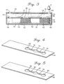
- FIG. 3 a second embodiment for analyzing blood is shown, also in accordance with the present invention.
- the embodiment of FIG. 3 operates in a similar manner as the embodiment previously described in connection with FIG. 1 and FIG. 2. Unlike the previous embodiment, however, the embodiment of FIG. 3 provides two separate reaction chambers, first reaction chamber 60 and second reaction chamber 62. These separate chambers 60 and 62 are particularly useful for analyzing different blood analytes, e.g., glucose, cholesterol or a lipid panel.
- the embodiment of FIG. 3 includes an application hole 64, access holes 66 and 68, metering chambers 70 and 72, metering capillaries 74 and 76 and air capillaries 78 and 80 which operate in virtually the same manner as their counterparts in FIG. 1.
- Blood is introduced through the application hole 64 into the first metering chamber 70 and, from the first metering chamber 70, into the first reaction chamber 60 and the first metering capillary 74, as previously described in connection with FIG. 1.
- the process that took place in connection with the first metering chamber 70 is duplicated in the second metering chamber 72 and, via the access hole 68, in the second reaction chamber 62.
- the key difference between these two respective processes involves the filtering and reaction in the reaction chambers 60 and 62, which are of course defined by the filter and reagent membrane types that are used.
- Metering capillaries 74 and 76 indicate when their associated metering chambers 70 and 72 have received an adequate amount of blood.
- the containment chamber 82, the air chamber 84, and the air vents 86 and 88 operate in the same manner as their counterparts in the embodiment of FIG. 1.
- FIGS. 4 and 5 respectively illustrate the first adhesive layer 114 and the second adhesive layer 116 of the embodiment of FIG. 3 from a perspective view.
- the present invention provides a unitized whole blood analyte assay strip useful for analysis with blood volumes as low 5 uL.
- the device does not require discrete operator metering or timing steps, and it provides complete sample containment of excess sample amounts.
- the metering capillary provides visual detection (human or instrumental) of an overfill or underfill condition and avoids the need for instrumental correction for hematocrit differences.
Abstract
Description
- The present invention relates generally to a device for analyzing blood and, more particularly, to a capillary device for analyzing blood using minimal sample volumes, e.g., fingerstick applications.
- Many diagnostic tests are carried out in the clinical field utilizing whole blood as a sample. These diagnostic tests often employ techniques that include separating the serum or plasma from the whole blood and using that serum or plasma as a test sample to obtain an accurate reading of blood analytes, such as glucose, cholesterol, potassium, etc.
- Traditionally, plasma and serum have been separated from whole blood by centrifugation. However, centrifugation is time consuming and requires equipment that is not generally available outside the clinical laboratory. Accordingly, field testing of the numerous blood substances that require the separation of serum or plasma is difficult.
- A number of devices have been devised to address this problem. These devices generally utilize filtering devices capable of various types of blood separation. Such filters have been implemented using paper, non-woven fabric, sheet-like filter material composed of powders or fibers, such as man-made fibers or glass fibers, and membrane filters having suitable pore sizes. Known diagnostic devices that employ such filters include U.S. Pat. No. 4,256,693, Kondo, et al., which discloses a number of filter materials used to test blood in a multi-layered integral chemical analysis device. U.S. Pat. No. 4,477,575, Vogel et al., describes a composition and process for permitting the separation of plasma or serum from whole blood utilizing glass fibers in combination with other absorbent layers. U.S. Pat. No. 4,753,776 to Hillman et al. describes a device which separates serum from the whole blood and, using capillary force, moves that serum to a separate compartment in the device to perform the diagnostic chemical reaction.
- These prior-art devices, unfortunately, have proven to be impractical or unsuitable for certain field applications. The patents to Kondo et al. and Vogel et al., for example, are unsuitable in applications which, due to space and volume constraints, require a small separation filter. Other problems associated with these prior-art techniques, including the patent to Hillman et al., involve a requirement for an excessive amount of blood, inadequate air venting for an accurate diagnostic reading of the reaction, an inability to handle excess blood, and/or they typically require the operator of the device to time or measure the amount of blood that is applied. These problems significantly hamper the diagnostic testing process. In many instances, added steps of measuring introduce intolerable delays.
- In accordance with a preferred embodiment of the present invention, a diagnostic device for analyzing blood analytes includes a housing with various chambers and compartments that process the blood. A sample application port (located in the top, end or side of the housing) is used to introduce blood into a metering chamber. From the metering chamber, the blood flows to a reaction chamber for analyzing blood analytes. Blood entering the metering chamber flows into a fluid capillary which indicates whether or not an adequate amount of blood has been received in the metering chamber. The reaction compartment can include a first chamber area for containing a reagent and a second chamber area, disposed between the metering chamber and the first chamber area, for containing a filter. The filter separates the solid components from the blood and passes the filtered material to the reagent which effects the desired reaction.
- Other objects and advantages of the invention will become apparent upon reading the following detailed description and upon reference to the accompanying drawings, in which:
- FIG. 1 provides a sectional view of a multi- layered blood analysis device, according to the present invention;
- FIG. 2 provides a perspective view of the blood analysis device of FIG. 1 with its layers shown separated from one another;
- FIG. 3 provides a sectional view of an alternate multi-layered blood analysis device, also in accordance with the present invention;
- FIG. 4 provides a perspective view of the first
adhesive layer 114 of the device of FIG. 3; and - FIG. 5 provides a perspective view of the second
adhesive layer 116 of the device of FIG. 3. - While the invention is susceptible to various modifications and alternative forms, specific embodiments thereof have been shown by way of example in the drawings and will herein be described in detail. It should be understood, however, that it is not intended to limit the invention to the particular forms disclosed. On the contrary, the intention is to cover all modifications, equivalents, and alternatives falling within the spirit and scope of the invention as defined by the appended claims.
- The present invention is particularly useful for detecting blood analytes with a sample volume as low as 5 micro-liters in the hematocrit range of 0% to 60% or higher. Such a minimum sample volume is typical in a fingerstick application. The above application is accomplished using a device that is constructed to provide a number of important advantages, including a self-metering function that allows the device to automatically indicate its blood sample volume requirement; thus, no timing or measuring of blood is necessary. In the following paragraphs, such a device is described in the form of a multi-layer laminate. It should be understood, however, that various other implementations could be used as well. For example, the device could be made using molded, cold-formed, and/or thermal- formed plastic parts.
- FIG. 1 illustrates this layered device. It includes a laminated multi-layered housing 10 having a
cover layer 12, a firstadhesive layer 14, acapillary cover layer 16, a secondadhesive layer 18 and abottom window layer 20. Additionally, anapplication seat 22 is included adjacent to thecover layer 12. These layers, of course, are shown from a cross-sectional perspective. - The laminated housing 10 employs the
application seat 22 to receiveblood 11, e.g., from a pierced finger or applicator. The point at which the blood enters through thecover layer 12 is referred to as theapplication hole 24 of the laminated housing 10. Theapplication hole 24 allows the blood to enter into ametering chamber 26, and, from themetering chamber 26, into a metering (fluid) capillary 28 and a reaction chamber orcompartment 34. The blood enters thereaction chamber 34 via anaccess hole 30. - The
metering chamber 26, theaccess hole 30 and the metering capillary 28 are constructed to provide the self-metering function referred to above. Theaccess hole 30 is offset from theapplication hole 24 so that as blood fills themetering chamber 26, a predetermined amount of blood covers theaccess hole 30 before the blood is drawn into themetering capillary 28. This predetermined amount of blood provides thereaction chamber 34, located just below theaccess hole 30, with an aliquot of blood to effect the desired diagnostic reaction. Thus, once themetering chamber 26 has received the necessary amount of blood for the reaction, the metering capillary 28 responds by carrying excess blood to thecontainment chamber 32. - This self-metering arrangement provides at least two significant advantages. First, it provides proper balance in the removal of excess blood through the
metering capillary 28. This allows the device to handle blood samples with high hematocrits (greater than about 50%). Additionally, because themetering capillary 28 quickly removes the blood from themetering chamber 26, the need for instrumental correction for hematocrit differences is avoided. - A second advantage concerns user convenience. For instance, the
containment chamber 32 is designed to hold an excess amount of blood that is well beyond the minimum amount required for the reaction. This allows the operator to overfill the device with the sample blood and latently react to the overfilled condition. Also, the laminated housing 10, illustrated as transparent, can be colored so that the overfill/underfill status is readily recognized by sample color by the operator from a top or bottom perspective. Thus, once the operator sees blood in themetering capillary 28, or in thecontainment chamber 32, the overfill condition is present; conversely, before blood is seen in themetering capillary 28, an underfill condition is present, and additional blood is needed. - The design is sufficiently flexible to change sample volume by changing chamber and capillary dimensions.
- With regard to the
reaction chamber 34, it contains afilter 40 and a reagent membrane 42 (which can include one or more layers) to provide the desired diagnostic reaction. Thefilter 40 is preferably an absorbent glass fiber. Thefilter 40 and thereagent membrane 42 are placed in thereaction chamber 34 such that they maintain intimate contact with its walls to prevent leakage resulting in red blood cells coming in contact with thereagent membrane 42. The size and location of theaccess hole 30 also helps to minimize leakage. Thefilter 40 can protrude into theaccess hole 30, acting as a wick to pull the blood into thereaction chamber 34 before the blood is pulled via themetering capillary 28. When an absorbent glass fiber is used to implement thefilter 40, the fiber surface should at least intimately contact the bottom surface of thecapillary cover layer 16 for efficient absorption of the blood into thereaction chamber 34. - Another important advantage of the present invention involves the construction of the
metering chamber 26 and thereaction chamber 34. The latter chamber provides filtration of red blood cells from the whole blood using a relatively small amount of blood. Moreover, when a glass fiber is used to implement thefilter 40, plasma is virtually, completely separated from whole blood with or without the use of additives. Thereagent membrane 42, which performs the analyte reaction mechanism (enzymatic/non-enzymatic), is capable of providing any needed final red cell separation. - The
metering chamber 26 and themetering capillary 28 are sufficiently vented throughair vent 44 to provide proper capillary flow and to allow themetering chamber 26 to be filled without trapping unwanted air. This is important, because, without such venting, capillary movement into themetering capillary 28 would not occur for high hematocrit samples. - Additional venting is provided by
air capillary 46, located adjacent to thebottom window layer 20, to allow air venting directly from thereaction chamber 34. From theair capillary 46, air flows into anair chamber 48 and, if necessary, out through thecontainment chamber 32 and theair vent 44. - The venting of the metering and
reaction chambers reaction chamber 34 can be provided by employing a hole in theair chamber 48, through thebottom window layer 20 or through the secondadhesive layer 18. - The air vents 44 and 52 can be manipulated in position and size to accommodate several purposes. For example, by making the diameter of the
air vent 44 larger than the diameter of theair vent 52, no blood will flow from thecontainment chamber 32 into theair chamber 48. By reversing these diameter sizes, a relatively large amount of excess blood will enter theair chamber 48. If both themetering capillary 28 and theair capillary 46 are run directly to the edge of the device and out through the walls of the firstadhesive layer 14 and the secondadhesive layer 18, respectively, there is no need for the air vents 44 and 52. - It is noted that in FIG. 1, the dotted lines are included in connection with both the
metering capillary 28 and theair capillary 46 to illustrate their capillary action from a cross-sectional view. The actual construction of thesecapillaries - Referring now to FIG. 2, the laminated multi- layered housing 10 of FIG. 1 is shown from a perspective view with the layers of the device separated. The dimensions of the layers can vary widely, but it has been found that a specific set of dimensions is particularly useful. These dimensions are set forth in the following paragraphs with reference to the device as shown in FIG. 2.
- The
cover layer 12 provides theapplication hole 24 and theair vent 44. Thecover layer 12 is 2 inches (5.1 cm) long, 0.3 inch (0.8 cm) wide and 0.004 inch (0.01 cm) thick. Theapplication hole 24 is about 0.2 inch (0.5 cm) in diameter, is centered with respect to the width of thecover layer 12 and is located 0.1 inch (0.3 cm) on center from the right side of thecover layer 12. Theair vent 44 in thecover layer 12 is centered with respect to the width of thecover layer 12, is centered about 0.7 inch (1.8 cm) from the right edge of thecover layer 12 and is 0.1 inch (0.5 cm) in diameter. - The first
adhesive layer 14, which provides themetering capillary 28 and the metering andcontainment chambers metering chamber 26 and thecontainment chamber 32 are both about 0.3 inch (0.8 cm) in diameter, centered with respect to the width of the firstadhesive layer 14 and interconnected by themetering capillary 28 which has a width of about 0.03 inch (0.08 cm). From the right side of the firstadhesive layer 14, themetering chamber 26 is about 0.2 inch (0.5 cm) on center, and thecontainment chamber 32 is 0.6 inch (1.5 cm) on center. - The
capillary cover layer 16 is constructed to provide theaccess hole 30 and theair vent 52, and a hydrophilic floor for themetering chamber 26 and themetering capillary 28. Thecapillary cover layer 16 is identical in length, width and thickness to thecover layer 12. The diameter of theaccess hole 30 is about 0.2 inch (0.5 cm). Theaccess hole 30 is centered with respect to the width of thecapillary cover layer 16, and may be offset from theapplication hole 24 of thecover layer 12 by about 0.1 inch (0.3 cm); thus, theaccess hole 30 is located 0.2 inch (0.5 cm) on center from the right side of thecapillary cover layer 16. Theair vent 52 is 0.1 inch (0.3 cm) in diameter, about 0.7 inch (1.8 cm) on center from the right side of thecapillary cover layer 16, and also centered with respect to the width of thecapillary cover layer 16. - The second
adhesive layer 18, which provides thereaction chamber 34, theair chamber 48 and theair capillary 46, is identical in length and width as the previously discussed layers. The thickness of the second adhesive layer is about 0.01 inch (0.03 cm). Thereaction chamber 34 and theair chamber 48 are both centered with respect to the width of the secondadhesive layer 18, about 0.2 inch (0.5 cm) in diameter, and interconnected by theair capillary 46 which has a width of about 0.03 inch (0.08 cm). The depth of theair capillary 46 should be at least the depth of thefilter 40, but can be as deep as theentire reaction chamber 34. From the right side of the secondadhesive layer 18, thereaction chamber 34 is located about 0.2 inch (0.5 cm) on center, and theair chamber 48 is located about 0.7 inch (1.8 cm) on center. Both thereagent membrane 42 and thefilter 40 are preferably about 0.2 inch (0.5 cm) (as determined by the elasticity of the material used) in diameter for a tight fit within the walls of thereaction chamber 34. - The
bottom window layer 20 is preferably optically clear for instrument reflectance measurements on the reagent membrane. Thebottom window layer 20 is 0.004 inch (0.01 cm) thick and may be implemented using the same length and width as the previously discussed layers. - Each of the
layers metering capillary 28 and thecontainment chamber 32. Thelayers - Referring now to FIG. 3, a second embodiment for analyzing blood is shown, also in accordance with the present invention. The embodiment of FIG. 3 operates in a similar manner as the embodiment previously described in connection with FIG. 1 and FIG. 2. Unlike the previous embodiment, however, the embodiment of FIG. 3 provides two separate reaction chambers,
first reaction chamber 60 andsecond reaction chamber 62. Theseseparate chambers application hole 64, access holes 66 and 68,metering chambers metering capillaries air capillaries - Blood is introduced through the
application hole 64 into thefirst metering chamber 70 and, from thefirst metering chamber 70, into thefirst reaction chamber 60 and thefirst metering capillary 74, as previously described in connection with FIG. 1. When a sufficient amount of excess blood flows through thefirst metering capillary 74 into thesecond metering chamber 72, the process that took place in connection with thefirst metering chamber 70 is duplicated in thesecond metering chamber 72 and, via theaccess hole 68, in thesecond reaction chamber 62. The key difference between these two respective processes involves the filtering and reaction in thereaction chambers Metering capillaries metering chambers - The
containment chamber 82, theair chamber 84, and the air vents 86 and 88 operate in the same manner as their counterparts in the embodiment of FIG. 1. - FIGS. 4 and 5 respectively illustrate the first
adhesive layer 114 and the secondadhesive layer 116 of the embodiment of FIG. 3 from a perspective view. - Accordingly, the present invention provides a unitized whole blood analyte assay strip useful for analysis with blood volumes as low 5 uL. The device does not require discrete operator metering or timing steps, and it provides complete sample containment of excess sample amounts. Moreover, the metering capillary provides visual detection (human or instrumental) of an overfill or underfill condition and avoids the need for instrumental correction for hematocrit differences.
- While the invention has been particularly shown and described with reference to multiple embodiments, as mentioned above, it will be understood by those skilled in the art that various other modifications and changes may be made as well. For example, the previously described embodiments can be modified to include several reaction chambers in a linear or radial array to allow for multiple blood analyte determinations using one drop of blood. Also, it is possible to have the application seat flush with the cover layer. For example, the cover layer could have a rounded depression which would constitute the application seat to receive blood. In addition, the application seat could be located on a side or on the end of the laminated multilayered housing for introduction of blood. This would permit the end loading or side loading of blood into the metering chamber. Such modifications and changes do not depart from the spirit and scope of the present invention which is set forth by the following claims.
Claims (10)
wherein the filter allows fluid entering the reaction compartment from the metering chamber to be filtered and the reagent reacts with the filtered fluid.
wherein the access port is offset from the sample application port toward the fluid capillary to allow an adequate amount of blood to fill the metering chamber before passing through the fluid capillary.
Applications Claiming Priority (2)
| Application Number | Priority Date | Filing Date | Title |
|---|---|---|---|
| US07/563,044 US5147606A (en) | 1990-08-06 | 1990-08-06 | Self-metering fluid analysis device |
| US563044 | 1990-08-06 |
Publications (2)
| Publication Number | Publication Date |
|---|---|
| EP0470438A1 true EP0470438A1 (en) | 1992-02-12 |
| EP0470438B1 EP0470438B1 (en) | 1995-07-12 |
Family
ID=24248876
Family Applications (1)
| Application Number | Title | Priority Date | Filing Date |
|---|---|---|---|
| EP91112399A Expired - Lifetime EP0470438B1 (en) | 1990-08-06 | 1991-07-24 | Self-metering fluid analysis device |
Country Status (6)
| Country | Link |
|---|---|
| US (1) | US5147606A (en) |
| EP (1) | EP0470438B1 (en) |
| JP (1) | JP2937568B2 (en) |
| AU (1) | AU626760B2 (en) |
| CA (1) | CA2047038C (en) |
| DE (1) | DE69111150T2 (en) |
Cited By (9)
| Publication number | Priority date | Publication date | Assignee | Title |
|---|---|---|---|---|
| US5478751A (en) * | 1993-12-29 | 1995-12-26 | Abbott Laboratories | Self-venting immunodiagnositic devices and methods of performing assays |
| EP0871886A1 (en) * | 1995-12-22 | 1998-10-21 | Universal Healthwatch, Inc. | Diagnostic assay providing plasma separation |
| EP1616189A2 (en) * | 2003-03-31 | 2006-01-18 | Cytonome, Inc. | Implementation of microfluidic components, including molecular fractionation devices, in a microfluidic system |
| EP1672349A2 (en) * | 2000-04-26 | 2006-06-21 | Arcturus Engineering, Inc. | Laser capture microdissection (lcm) extraction device and device carrier and method for post-lcm fluid processing |
| US7514000B2 (en) | 2002-09-09 | 2009-04-07 | Cytonome, Inc. | Implementation of microfluidic components, including molecular fractionation devices, in a microfluidic system |
| WO2009125092A2 (en) * | 2008-03-31 | 2009-10-15 | Commissariat A L'energie Atomique | Device for aliquoting and filtering blood |
| US7842235B2 (en) | 2004-02-14 | 2010-11-30 | Roche Diagnostics Operations, Inc. | Test element, system, and method of controlling the wetting of same |
| EP2281631A1 (en) * | 2009-08-07 | 2011-02-09 | Atonomics A/S | Modular microfluidic sample preparation system and method of mixing and delivering a sample fluid. |
| CN106226254A (en) * | 2016-08-03 | 2016-12-14 | 天津喜诺生物医药有限公司 | A kind of micro-fluidic chip for biological detection and preparation method thereof |
Families Citing this family (138)
| Publication number | Priority date | Publication date | Assignee | Title |
|---|---|---|---|---|
| US4935346A (en) | 1986-08-13 | 1990-06-19 | Lifescan, Inc. | Minimum procedure system for the determination of analytes |
| US5587128A (en) | 1992-05-01 | 1996-12-24 | The Trustees Of The University Of Pennsylvania | Mesoscale polynucleotide amplification devices |
| US5498392A (en) * | 1992-05-01 | 1996-03-12 | Trustees Of The University Of Pennsylvania | Mesoscale polynucleotide amplification device and method |
| US5637469A (en) | 1992-05-01 | 1997-06-10 | Trustees Of The University Of Pennsylvania | Methods and apparatus for the detection of an analyte utilizing mesoscale flow systems |
| US6953676B1 (en) * | 1992-05-01 | 2005-10-11 | Trustees Of The University Of Pennsylvania | Mesoscale polynucleotide amplification device and method |
| US5744366A (en) * | 1992-05-01 | 1998-04-28 | Trustees Of The University Of Pennsylvania | Mesoscale devices and methods for analysis of motile cells |
| US5726026A (en) * | 1992-05-01 | 1998-03-10 | Trustees Of The University Of Pennsylvania | Mesoscale sample preparation device and systems for determination and processing of analytes |
| US5296375A (en) * | 1992-05-01 | 1994-03-22 | Trustees Of The University Of Pennsylvania | Mesoscale sperm handling devices |
| US5486335A (en) * | 1992-05-01 | 1996-01-23 | Trustees Of The University Of Pennsylvania | Analysis based on flow restriction |
| US5304487A (en) * | 1992-05-01 | 1994-04-19 | Trustees Of The University Of Pennsylvania | Fluid handling in mesoscale analytical devices |
| US5302348A (en) * | 1992-12-10 | 1994-04-12 | Itc Corporation | Blood coagulation time test apparatus and method |
| DE4303860C2 (en) * | 1993-02-10 | 1995-11-09 | Draegerwerk Ag | Carrier for colorimetric gas detection in composite film construction |
| US5427663A (en) * | 1993-06-08 | 1995-06-27 | British Technology Group Usa Inc. | Microlithographic array for macromolecule and cell fractionation |
| US5399317A (en) * | 1993-07-16 | 1995-03-21 | California Institute Of Technology | Reaction cell for protein sequencer and the like |
| US5725831A (en) * | 1994-03-14 | 1998-03-10 | Becton Dickinson And Company | Nucleic acid amplification apparatus |
| CA2143365A1 (en) * | 1994-03-14 | 1995-09-15 | Hugh V. Cottingham | Nucleic acid amplification method and apparatus |
| US5589399A (en) * | 1994-10-21 | 1996-12-31 | First Medical, Inc. | System and method for plasma separation and measurement |
| US5916521A (en) * | 1995-01-04 | 1999-06-29 | Spectral Diagnostics, Inc. | Lateral flow filter devices for separation of body fluids from particulate materials |
| US5674395A (en) * | 1995-06-05 | 1997-10-07 | Millipore Corporation | Multiple sample separator |
| US6048734A (en) | 1995-09-15 | 2000-04-11 | The Regents Of The University Of Michigan | Thermal microvalves in a fluid flow method |
| US5698162A (en) * | 1996-02-27 | 1997-12-16 | Johnson & Johnson Clinical Diagnostics | Apparatus for staining of cells and tissues |
| US6165739A (en) * | 1996-03-13 | 2000-12-26 | Compucyte Corporation | Multiple simultaneous testing media |
| US5942443A (en) * | 1996-06-28 | 1999-08-24 | Caliper Technologies Corporation | High throughput screening assay systems in microscale fluidic devices |
| US20020010406A1 (en) | 1996-05-17 | 2002-01-24 | Douglas Joel S. | Methods and apparatus for expressing body fluid from an incision |
| EP1579814A3 (en) | 1996-05-17 | 2006-06-14 | Roche Diagnostics Operations, Inc. | Methods and apparatus for sampling and analyzing body fluid |
| CN1173776C (en) * | 1996-06-28 | 2004-11-03 | 卡钳技术有限公司 | High-throughput screening assay systems in microscale fluidic devices |
| AU4164597A (en) | 1996-08-26 | 1998-03-19 | Princeton University | Reversibly sealable microstructure sorting devices |
| DE29723400U1 (en) * | 1996-10-30 | 1998-09-10 | Mercury Diagnostics Inc | Synchronized analysis test system |
| US6090251A (en) | 1997-06-06 | 2000-07-18 | Caliper Technologies, Inc. | Microfabricated structures for facilitating fluid introduction into microfluidic devices |
| US5948695A (en) | 1997-06-17 | 1999-09-07 | Mercury Diagnostics, Inc. | Device for determination of an analyte in a body fluid |
| DE19753850A1 (en) * | 1997-12-04 | 1999-06-10 | Roche Diagnostics Gmbh | Sampling device |
| DE19753847A1 (en) | 1997-12-04 | 1999-06-10 | Roche Diagnostics Gmbh | Analytical test element with capillary channel |
| US6267722B1 (en) | 1998-02-03 | 2001-07-31 | Adeza Biomedical Corporation | Point of care diagnostic systems |
| US6394952B1 (en) | 1998-02-03 | 2002-05-28 | Adeza Biomedical Corporation | Point of care diagnostic systems |
| USD432244S (en) * | 1998-04-20 | 2000-10-17 | Adeza Biomedical Corporation | Device for encasing an assay test strip |
| USD434153S (en) * | 1998-04-20 | 2000-11-21 | Adeza Biomedical Corporation | Point of care analyte detector system |
| US6077660A (en) * | 1998-06-10 | 2000-06-20 | Abbott Laboratories | Diagnostic assay requiring a small sample of biological fluid |
| US6312888B1 (en) | 1998-06-10 | 2001-11-06 | Abbott Laboratories | Diagnostic assay for a sample of biological fluid |
| US6908770B1 (en) | 1998-07-16 | 2005-06-21 | Board Of Regents, The University Of Texas System | Fluid based analysis of multiple analytes by a sensor array |
| US6240790B1 (en) * | 1998-11-09 | 2001-06-05 | Agilent Technologies, Inc. | Device for high throughout sample processing, analysis and collection, and methods of use thereof |
| US6296702B1 (en) * | 1999-03-15 | 2001-10-02 | Pe Corporation (Ny) | Apparatus and method for spotting a substrate |
| US6551842B1 (en) | 1999-03-26 | 2003-04-22 | Idexx Laboratories, Inc. | Method and device for detecting analytes in fluids |
| US6602719B1 (en) | 1999-03-26 | 2003-08-05 | Idexx Laboratories, Inc. | Method and device for detecting analytes in fluids |
| US6511814B1 (en) | 1999-03-26 | 2003-01-28 | Idexx Laboratories, Inc. | Method and device for detecting analytes in fluids |
| US6818185B1 (en) | 1999-05-28 | 2004-11-16 | Cepheid | Cartridge for conducting a chemical reaction |
| US6589779B1 (en) | 1999-07-16 | 2003-07-08 | Board Of Regents, The University Of Texas System | General signaling protocol for chemical receptors in immobilized matrices |
| US7022517B1 (en) | 1999-07-16 | 2006-04-04 | Board Of Regents, The University Of Texas System | Method and apparatus for the delivery of samples to a chemical sensor array |
| WO2001036666A1 (en) * | 1999-11-15 | 2001-05-25 | I-Stat Corporation | Apparatus and method for assaying coagulation in fluid samples |
| US6458326B1 (en) | 1999-11-24 | 2002-10-01 | Home Diagnostics, Inc. | Protective test strip platform |
| DE60135092D1 (en) | 2000-01-31 | 2008-09-11 | Univ Texas | PORTABLE DEVICE WITH A SENSOR ARRAY ARRANGEMENT |
| AU2001259241A1 (en) | 2000-04-26 | 2001-11-07 | Arcturus Engineering, Inc. | Laser capture microdissection (lcm) extraction device and device carrier and method for post-lcm fluid processing |
| DE10046173C2 (en) * | 2000-09-08 | 2003-04-03 | Inst Chemo Biosensorik | Device and method for separating undissolved components from biological liquids |
| US6913697B2 (en) | 2001-02-14 | 2005-07-05 | Science & Technology Corporation @ Unm | Nanostructured separation and analysis devices for biological membranes |
| US6692700B2 (en) | 2001-02-14 | 2004-02-17 | Handylab, Inc. | Heat-reduction methods and systems related to microfluidic devices |
| US6525330B2 (en) | 2001-02-28 | 2003-02-25 | Home Diagnostics, Inc. | Method of strip insertion detection |
| US6541266B2 (en) | 2001-02-28 | 2003-04-01 | Home Diagnostics, Inc. | Method for determining concentration of an analyte in a test strip |
| US6852287B2 (en) * | 2001-09-12 | 2005-02-08 | Handylab, Inc. | Microfluidic devices having a reduced number of input and output connections |
| US7323140B2 (en) | 2001-03-28 | 2008-01-29 | Handylab, Inc. | Moving microdroplets in a microfluidic device |
| US8895311B1 (en) | 2001-03-28 | 2014-11-25 | Handylab, Inc. | Methods and systems for control of general purpose microfluidic devices |
| US7829025B2 (en) | 2001-03-28 | 2010-11-09 | Venture Lending & Leasing Iv, Inc. | Systems and methods for thermal actuation of microfluidic devices |
| US7192557B2 (en) | 2001-03-28 | 2007-03-20 | Handylab, Inc. | Methods and systems for releasing intracellular material from cells within microfluidic samples of fluids |
| US6575188B2 (en) | 2001-07-26 | 2003-06-10 | Handylab, Inc. | Methods and systems for fluid control in microfluidic devices |
| US7010391B2 (en) | 2001-03-28 | 2006-03-07 | Handylab, Inc. | Methods and systems for control of microfluidic devices |
| US7270786B2 (en) | 2001-03-28 | 2007-09-18 | Handylab, Inc. | Methods and systems for processing microfluidic samples of particle containing fluids |
| WO2003025559A1 (en) * | 2001-09-11 | 2003-03-27 | Arkray, Inc. | Measuring instrument, installation body, and density measurer |
| US6989891B2 (en) | 2001-11-08 | 2006-01-24 | Optiscan Biomedical Corporation | Device and method for in vitro determination of analyte concentrations within body fluids |
| US7069952B1 (en) | 2001-11-14 | 2006-07-04 | Caliper Life Sciences, Inc. | Microfluidic devices and methods of their manufacture |
| AU2003228711C1 (en) | 2002-04-26 | 2010-01-07 | Board Of Regents, The University Of Texas System | Method and system for the detection of cardiac risk factors |
| EP1364710B1 (en) * | 2002-05-13 | 2009-10-07 | Becton, Dickinson and Company | Self-aliquoting sample storage plate |
| DE10234819A1 (en) * | 2002-07-31 | 2004-02-19 | Roche Diagnostics Gmbh | Test apparatus for blood, comprising compound body with test strip levels and transport channels to give complex tests in compact structure |
| ATE531257T1 (en) | 2002-09-27 | 2011-11-15 | Gen Hospital Corp | MICROFLUIDIC DEVICE FOR CELL SEPARATION AND USES THEREOF |
| EP1590659A4 (en) * | 2003-02-07 | 2010-04-21 | Univ Texas | Multi-shell microspheres with integrated chomatographic and detection layers for use in array sensors |
| EP2402089A1 (en) | 2003-07-31 | 2012-01-04 | Handylab, Inc. | Processing particle-containing samples |
| US8105849B2 (en) | 2004-02-27 | 2012-01-31 | Board Of Regents, The University Of Texas System | Integration of fluids and reagents into self-contained cartridges containing sensor elements |
| US8101431B2 (en) | 2004-02-27 | 2012-01-24 | Board Of Regents, The University Of Texas System | Integration of fluids and reagents into self-contained cartridges containing sensor elements and reagent delivery systems |
| US8852862B2 (en) | 2004-05-03 | 2014-10-07 | Handylab, Inc. | Method for processing polynucleotide-containing samples |
| WO2005108620A2 (en) | 2004-05-03 | 2005-11-17 | Handylab, Inc. | Processing polynucleotide-containing samples |
| US8936755B2 (en) | 2005-03-02 | 2015-01-20 | Optiscan Biomedical Corporation | Bodily fluid composition analyzer with disposable cassette |
| US7907985B2 (en) | 2005-02-14 | 2011-03-15 | Optiscan Biomedical Corporation | Fluid handling cassette with a fluid control interface and sample separator |
| US20070196820A1 (en) | 2005-04-05 | 2007-08-23 | Ravi Kapur | Devices and methods for enrichment and alteration of cells and other particles |
| US8377398B2 (en) | 2005-05-31 | 2013-02-19 | The Board Of Regents Of The University Of Texas System | Methods and compositions related to determination and use of white blood cell counts |
| US8921102B2 (en) | 2005-07-29 | 2014-12-30 | Gpb Scientific, Llc | Devices and methods for enrichment and alteration of circulating tumor cells and other particles |
| US9561001B2 (en) | 2005-10-06 | 2017-02-07 | Optiscan Biomedical Corporation | Fluid handling cassette system for body fluid analyzer |
| US10900066B2 (en) | 2006-03-24 | 2021-01-26 | Handylab, Inc. | Microfluidic system for amplifying and detecting polynucleotides in parallel |
| US8088616B2 (en) | 2006-03-24 | 2012-01-03 | Handylab, Inc. | Heater unit for microfluidic diagnostic system |
| US11806718B2 (en) | 2006-03-24 | 2023-11-07 | Handylab, Inc. | Fluorescence detector for microfluidic diagnostic system |
| EP2001990B1 (en) | 2006-03-24 | 2016-06-29 | Handylab, Inc. | Integrated system for processing microfluidic samples, and method of using same |
| US7998708B2 (en) | 2006-03-24 | 2011-08-16 | Handylab, Inc. | Microfluidic system for amplifying and detecting polynucleotides in parallel |
| US8169600B2 (en) * | 2006-09-15 | 2012-05-01 | Arryx, Inc. | Surface mapping by optical manipulation of particles in relation to a functionalized surface |
| WO2008060604A2 (en) | 2006-11-14 | 2008-05-22 | Handylab, Inc. | Microfluidic system for amplifying and detecting polynucleotides in parallel |
| WO2008061165A2 (en) | 2006-11-14 | 2008-05-22 | Handylab, Inc. | Microfluidic cartridge and method of making same |
| US8182763B2 (en) | 2007-07-13 | 2012-05-22 | Handylab, Inc. | Rack for sample tubes and reagent holders |
| US9186677B2 (en) | 2007-07-13 | 2015-11-17 | Handylab, Inc. | Integrated apparatus for performing nucleic acid extraction and diagnostic testing on multiple biological samples |
| EP3741869A1 (en) | 2007-07-13 | 2020-11-25 | Handylab, Inc. | Polynucleotide capture materials and methods of using same |
| US8287820B2 (en) | 2007-07-13 | 2012-10-16 | Handylab, Inc. | Automated pipetting apparatus having a combined liquid pump and pipette head system |
| US8105783B2 (en) | 2007-07-13 | 2012-01-31 | Handylab, Inc. | Microfluidic cartridge |
| US8133671B2 (en) | 2007-07-13 | 2012-03-13 | Handylab, Inc. | Integrated apparatus for performing nucleic acid extraction and diagnostic testing on multiple biological samples |
| US20090136385A1 (en) | 2007-07-13 | 2009-05-28 | Handylab, Inc. | Reagent Tube |
| USD621060S1 (en) | 2008-07-14 | 2010-08-03 | Handylab, Inc. | Microfluidic cartridge |
| US9618139B2 (en) | 2007-07-13 | 2017-04-11 | Handylab, Inc. | Integrated heater and magnetic separator |
| KR100905954B1 (en) * | 2007-07-23 | 2009-07-06 | 주식회사 디지탈바이오테크놀러지 | Module for detecting analytes in fluids and chip having the same |
| US9404911B2 (en) * | 2008-04-21 | 2016-08-02 | Quidel Corporation | Integrated assay device and housing |
| USD618820S1 (en) | 2008-07-11 | 2010-06-29 | Handylab, Inc. | Reagent holder |
| USD787087S1 (en) | 2008-07-14 | 2017-05-16 | Handylab, Inc. | Housing |
| EP2437887B1 (en) | 2009-06-04 | 2016-05-11 | Lockheed Martin Corporation | Multiple-sample microfluidic chip for dna analysis |
| EP2456355B1 (en) | 2009-07-20 | 2016-09-14 | Optiscan Biomedical Corporation | Adjustable connector and dead space reduction |
| US9554742B2 (en) | 2009-07-20 | 2017-01-31 | Optiscan Biomedical Corporation | Fluid analysis system |
| EP2502075B1 (en) * | 2009-11-16 | 2015-07-15 | Silicon Biodevices, Inc. | Filtration device for assays |
| EP2580589B1 (en) | 2010-06-09 | 2016-08-31 | Optiscan Biomedical Corporation | Measuring analytes in a fluid sample drawn from a patient |
| MX2013004184A (en) | 2010-10-15 | 2013-07-29 | Lockheed Corp | Micro fluidic optic design. |
| CA2833262C (en) | 2011-04-15 | 2020-08-18 | Becton, Dickinson And Company | Scanning real-time microfluidic thermocycler and methods for synchronized thermocycling and scanning optical detection |
| US9541480B2 (en) | 2011-06-29 | 2017-01-10 | Academia Sinica | Capture, purification, and release of biological substances using a surface coating |
| WO2013006716A1 (en) | 2011-07-06 | 2013-01-10 | Optiscan Biomedical Corporation | Sample cell for fluid analysis system |
| KR102121853B1 (en) | 2011-09-30 | 2020-06-12 | 벡톤 디킨슨 앤드 컴퍼니 | Unitized reagent strip |
| USD692162S1 (en) | 2011-09-30 | 2013-10-22 | Becton, Dickinson And Company | Single piece reagent holder |
| CN104040238B (en) | 2011-11-04 | 2017-06-27 | 汉迪拉布公司 | Polynucleotides sample preparation apparatus |
| JP6251192B2 (en) * | 2012-01-24 | 2017-12-20 | コーニンクレッカ フィリップス エヌ ヴェKoninklijke Philips N.V. | Analysis cartridge using filter unit |
| CA2863637C (en) | 2012-02-03 | 2021-10-26 | Becton, Dickinson And Company | External files for distribution of molecular diagnostic tests and determination of compatibility between tests |
| US9322054B2 (en) | 2012-02-22 | 2016-04-26 | Lockheed Martin Corporation | Microfluidic cartridge |
| US9150907B2 (en) * | 2012-04-27 | 2015-10-06 | General Electric Company | Microfluidic flow cell assemblies and method of use |
| US8900529B2 (en) * | 2012-04-27 | 2014-12-02 | General Electric Company | Microfluidic chamber device and fabrication |
| US9080941B2 (en) * | 2012-04-27 | 2015-07-14 | General Electric Company | Microfluidic flow cell assemblies for imaging and method of use |
| US9389208B2 (en) * | 2013-01-25 | 2016-07-12 | Rosemount Analytical Inc. | Hermetic manifold for analytical instruments |
| KR20150039051A (en) * | 2013-10-01 | 2015-04-09 | 삼성전자주식회사 | Blood filter device separating plasma or serum from blood and the use thereof |
| EP3126814B1 (en) | 2014-04-01 | 2019-06-12 | Academia Sinica | Methods and systems for cancer diagnosis and prognosis |
| WO2015175188A1 (en) * | 2014-05-14 | 2015-11-19 | General Electric Company | Microfluidic flow cell assemblies for imaging and method of use |
| EP3143380B1 (en) * | 2014-05-15 | 2020-04-15 | General Electric Company | Microfluidic flow cell assemblies and method of use |
| WO2015187849A2 (en) | 2014-06-04 | 2015-12-10 | Lucigen Corporation | Sample collection and analysis devices |
| JP6359348B2 (en) * | 2014-06-06 | 2018-07-18 | キヤノンメディカルシステムズ株式会社 | Sensor chip and liquid supply method to sensor chip |
| EP3174573A4 (en) * | 2014-08-01 | 2017-10-04 | Siemens Healthcare Diagnostics Inc. | Vacuum-assisted plasma separation |
| US10214772B2 (en) * | 2015-06-22 | 2019-02-26 | Fluxergy, Llc | Test card for assay and method of manufacturing same |
| KR20170002084A (en) * | 2015-06-29 | 2017-01-06 | 삼성전자주식회사 | Cartrige for analysis and auxiliary device |
| US10107726B2 (en) * | 2016-03-16 | 2018-10-23 | Cellmax, Ltd. | Collection of suspended cells using a transferable membrane |
| US10293340B2 (en) | 2017-10-11 | 2019-05-21 | Fitbit, Inc. | Microfluidic metering and delivery system |
| US11906531B2 (en) | 2018-07-10 | 2024-02-20 | Calmark Sweden Ab | Method of detecting the presence of a biomarker in a sample of a flowable substance, a detector assembly for use in the detection of a biomarker in a sample of a flowable substance and a detector unit for use in the detection of the presence of a biomarker in a sample of a flowable substance |
| CN108704684B (en) * | 2018-09-04 | 2023-06-06 | 重庆科技学院 | Use method of multilayer microfluidic chip for detection |
| US20210316300A1 (en) * | 2018-09-06 | 2021-10-14 | Capitainer Ab | A microfluidic device |
| WO2023162095A1 (en) * | 2022-02-24 | 2023-08-31 | セルスペクト株式会社 | Blood testing device |
Citations (4)
| Publication number | Priority date | Publication date | Assignee | Title |
|---|---|---|---|---|
| EP0206561A2 (en) * | 1985-05-31 | 1986-12-30 | Murex Corporation | Diagnostic device |
| EP0269240A1 (en) * | 1986-10-29 | 1988-06-01 | Biotrack, Inc. | Blood separation device under low pressure conditions |
| EP0281201A1 (en) * | 1987-03-03 | 1988-09-07 | PB Diagnostic Systems, Inc. | Self contained immunoassay element |
| EP0286371A2 (en) * | 1987-04-07 | 1988-10-12 | Syntex (U.S.A.) Inc. | Immunoassay device |
Family Cites Families (4)
| Publication number | Priority date | Publication date | Assignee | Title |
|---|---|---|---|---|
| JPS587332Y2 (en) * | 1978-06-06 | 1983-02-08 | 富士写真フイルム株式会社 | Multilayer blood chemistry analysis material |
| DE3029579C2 (en) * | 1980-08-05 | 1985-12-12 | Boehringer Mannheim Gmbh, 6800 Mannheim | Method and means for separating plasma or serum from whole blood |
| DE3729001A1 (en) * | 1987-08-31 | 1989-03-09 | Behringwerke Ag | DEVICE AND METHOD FOR SEPARATING BLOOD CELLS FROM BODY LIQUIDS CONTAINING ERYTHROCYTES AND THE USE THEREOF |
| AU640186B2 (en) * | 1989-12-28 | 1993-08-19 | Pall Corporation | Device and method for blood separation |
-
1990
- 1990-08-06 US US07/563,044 patent/US5147606A/en not_active Expired - Lifetime
-
1991
- 1991-07-15 CA CA002047038A patent/CA2047038C/en not_active Expired - Lifetime
- 1991-07-23 AU AU81296/91A patent/AU626760B2/en not_active Ceased
- 1991-07-24 EP EP91112399A patent/EP0470438B1/en not_active Expired - Lifetime
- 1991-07-24 DE DE69111150T patent/DE69111150T2/en not_active Expired - Fee Related
- 1991-08-02 JP JP3216628A patent/JP2937568B2/en not_active Expired - Fee Related
Patent Citations (4)
| Publication number | Priority date | Publication date | Assignee | Title |
|---|---|---|---|---|
| EP0206561A2 (en) * | 1985-05-31 | 1986-12-30 | Murex Corporation | Diagnostic device |
| EP0269240A1 (en) * | 1986-10-29 | 1988-06-01 | Biotrack, Inc. | Blood separation device under low pressure conditions |
| EP0281201A1 (en) * | 1987-03-03 | 1988-09-07 | PB Diagnostic Systems, Inc. | Self contained immunoassay element |
| EP0286371A2 (en) * | 1987-04-07 | 1988-10-12 | Syntex (U.S.A.) Inc. | Immunoassay device |
Cited By (14)
| Publication number | Priority date | Publication date | Assignee | Title |
|---|---|---|---|---|
| US5478751A (en) * | 1993-12-29 | 1995-12-26 | Abbott Laboratories | Self-venting immunodiagnositic devices and methods of performing assays |
| EP0871886A1 (en) * | 1995-12-22 | 1998-10-21 | Universal Healthwatch, Inc. | Diagnostic assay providing plasma separation |
| EP0871886A4 (en) * | 1995-12-22 | 2001-06-27 | Universal Healthwatch Inc | Diagnostic assay providing plasma separation |
| EP1672349A2 (en) * | 2000-04-26 | 2006-06-21 | Arcturus Engineering, Inc. | Laser capture microdissection (lcm) extraction device and device carrier and method for post-lcm fluid processing |
| EP1672349A3 (en) * | 2000-04-26 | 2014-02-19 | Life Technologies Corporation | Laser capture microdissection (lcm) extraction device and device carrier and method for post-lcm fluid processing |
| US7514000B2 (en) | 2002-09-09 | 2009-04-07 | Cytonome, Inc. | Implementation of microfluidic components, including molecular fractionation devices, in a microfluidic system |
| EP1616189A2 (en) * | 2003-03-31 | 2006-01-18 | Cytonome, Inc. | Implementation of microfluidic components, including molecular fractionation devices, in a microfluidic system |
| EP1616189A4 (en) * | 2003-03-31 | 2007-10-17 | Cytonome Inc | Implementation of microfluidic components, including molecular fractionation devices, in a microfluidic system |
| US7842235B2 (en) | 2004-02-14 | 2010-11-30 | Roche Diagnostics Operations, Inc. | Test element, system, and method of controlling the wetting of same |
| WO2009125092A2 (en) * | 2008-03-31 | 2009-10-15 | Commissariat A L'energie Atomique | Device for aliquoting and filtering blood |
| WO2009125092A3 (en) * | 2008-03-31 | 2009-12-10 | Commissariat A L'energie Atomique | Device for aliquoting and filtering blood |
| EP2281631A1 (en) * | 2009-08-07 | 2011-02-09 | Atonomics A/S | Modular microfluidic sample preparation system and method of mixing and delivering a sample fluid. |
| CN106226254A (en) * | 2016-08-03 | 2016-12-14 | 天津喜诺生物医药有限公司 | A kind of micro-fluidic chip for biological detection and preparation method thereof |
| CN106226254B (en) * | 2016-08-03 | 2019-06-07 | 天津喜诺生物医药有限公司 | A kind of micro-fluidic chip and preparation method thereof for biological detection |
Also Published As
| Publication number | Publication date |
|---|---|
| JPH04232855A (en) | 1992-08-21 |
| CA2047038C (en) | 2001-09-11 |
| AU626760B2 (en) | 1992-08-06 |
| DE69111150T2 (en) | 1995-11-23 |
| US5147606A (en) | 1992-09-15 |
| DE69111150D1 (en) | 1995-08-17 |
| JP2937568B2 (en) | 1999-08-23 |
| AU8129691A (en) | 1992-02-20 |
| EP0470438B1 (en) | 1995-07-12 |
| CA2047038A1 (en) | 1992-02-07 |
Similar Documents
| Publication | Publication Date | Title |
|---|---|---|
| EP0470438B1 (en) | Self-metering fluid analysis device | |
| US5208163A (en) | Self-metering fluid analysis device | |
| CA2109704C (en) | Analytical cartridge and system for detecting analytes | |
| AU775559B2 (en) | Microdroplet dispensing for a medical diagnostic device | |
| US4918025A (en) | Self contained immunoassay element | |
| EP0034049B1 (en) | Test device for analysis of a plurality of analytes | |
| AU752645B2 (en) | Fluidic device for medical diagnostics | |
| EP0974840B1 (en) | Fluidic device for medical diagnostics | |
| US7008799B1 (en) | Analytical test element with a capillary channel | |
| EP1240945B1 (en) | Device and method for analyzing a sample | |
| AU764945B2 (en) | Multiple analyte assay device with sample integrity monitoring system | |
| WO1999052633A1 (en) | Test cartridge with a single inlet port | |
| CA2115672A1 (en) | Method and device for metering of fluid samples | |
| US7820451B2 (en) | Analytical test element | |
| EP0640392B1 (en) | Analyte detection device |
Legal Events
| Date | Code | Title | Description |
|---|---|---|---|
| PUAI | Public reference made under article 153(3) epc to a published international application that has entered the european phase |
Free format text: ORIGINAL CODE: 0009012 |
|
| AK | Designated contracting states |
Kind code of ref document: A1 Designated state(s): DE FR GB IT |
|
| 17P | Request for examination filed |
Effective date: 19920304 |
|
| 17Q | First examination report despatched |
Effective date: 19940331 |
|
| ITPR | It: changes in ownership of a european patent |
Owner name: C.N.EPO REG.92;(ORA) BAYER CORPORATION |
|
| GRAA | (expected) grant |
Free format text: ORIGINAL CODE: 0009210 |
|
| RAP1 | Party data changed (applicant data changed or rights of an application transferred) |
Owner name: BAYER CORPORATION |
|
| AK | Designated contracting states |
Kind code of ref document: B1 Designated state(s): DE FR GB IT |
|
| RAP2 | Party data changed (patent owner data changed or rights of a patent transferred) |
Owner name: BAYER CORPORATION |
|
| REF | Corresponds to: |
Ref document number: 69111150 Country of ref document: DE Date of ref document: 19950817 |
|
| ET | Fr: translation filed | ||
| ITF | It: translation for a ep patent filed |
Owner name: ING. C. GREGORJ S.P.A. |
|
| PLBE | No opposition filed within time limit |
Free format text: ORIGINAL CODE: 0009261 |
|
| STAA | Information on the status of an ep patent application or granted ep patent |
Free format text: STATUS: NO OPPOSITION FILED WITHIN TIME LIMIT |
|
| 26N | No opposition filed | ||
| REG | Reference to a national code |
Ref country code: GB Ref legal event code: IF02 |
|
| PGFP | Annual fee paid to national office [announced via postgrant information from national office to epo] |
Ref country code: DE Payment date: 20080829 Year of fee payment: 18 |
|
| PGFP | Annual fee paid to national office [announced via postgrant information from national office to epo] |
Ref country code: IT Payment date: 20080728 Year of fee payment: 18 Ref country code: FR Payment date: 20080729 Year of fee payment: 18 |
|
| PGFP | Annual fee paid to national office [announced via postgrant information from national office to epo] |
Ref country code: GB Payment date: 20080729 Year of fee payment: 18 |
|
| GBPC | Gb: european patent ceased through non-payment of renewal fee |
Effective date: 20090724 |
|
| REG | Reference to a national code |
Ref country code: FR Ref legal event code: ST Effective date: 20100331 |
|
| PG25 | Lapsed in a contracting state [announced via postgrant information from national office to epo] |
Ref country code: FR Free format text: LAPSE BECAUSE OF NON-PAYMENT OF DUE FEES Effective date: 20090731 |
|
| PG25 | Lapsed in a contracting state [announced via postgrant information from national office to epo] |
Ref country code: GB Free format text: LAPSE BECAUSE OF NON-PAYMENT OF DUE FEES Effective date: 20090724 |
|
| PG25 | Lapsed in a contracting state [announced via postgrant information from national office to epo] |
Ref country code: DE Free format text: LAPSE BECAUSE OF NON-PAYMENT OF DUE FEES Effective date: 20100202 |
|
| PG25 | Lapsed in a contracting state [announced via postgrant information from national office to epo] |
Ref country code: IT Free format text: LAPSE BECAUSE OF NON-PAYMENT OF DUE FEES Effective date: 20090724 |