EP0469882A2 - Image processing apparatus - Google Patents
Image processing apparatus Download PDFInfo
- Publication number
- EP0469882A2 EP0469882A2 EP91307010A EP91307010A EP0469882A2 EP 0469882 A2 EP0469882 A2 EP 0469882A2 EP 91307010 A EP91307010 A EP 91307010A EP 91307010 A EP91307010 A EP 91307010A EP 0469882 A2 EP0469882 A2 EP 0469882A2
- Authority
- EP
- European Patent Office
- Prior art keywords
- pattern information
- image data
- pattern
- binarization
- value image
- Prior art date
- Legal status (The legal status is an assumption and is not a legal conclusion. Google has not performed a legal analysis and makes no representation as to the accuracy of the status listed.)
- Granted
Links
Images


Classifications
-
- G—PHYSICS
- G06—COMPUTING; CALCULATING OR COUNTING
- G06K—GRAPHICAL DATA READING; PRESENTATION OF DATA; RECORD CARRIERS; HANDLING RECORD CARRIERS
- G06K15/00—Arrangements for producing a permanent visual presentation of the output data, e.g. computer output printers
-
- G—PHYSICS
- G06—COMPUTING; CALCULATING OR COUNTING
- G06V—IMAGE OR VIDEO RECOGNITION OR UNDERSTANDING
- G06V30/00—Character recognition; Recognising digital ink; Document-oriented image-based pattern recognition
- G06V30/10—Character recognition
- G06V30/16—Image preprocessing
- G06V30/162—Quantising the image signal
-
- H—ELECTRICITY
- H04—ELECTRIC COMMUNICATION TECHNIQUE
- H04N—PICTORIAL COMMUNICATION, e.g. TELEVISION
- H04N1/00—Scanning, transmission or reproduction of documents or the like, e.g. facsimile transmission; Details thereof
- H04N1/40—Picture signal circuits
- H04N1/405—Halftoning, i.e. converting the picture signal of a continuous-tone original into a corresponding signal showing only two levels
- H04N1/4055—Halftoning, i.e. converting the picture signal of a continuous-tone original into a corresponding signal showing only two levels producing a clustered dots or a size modulated halftone pattern
-
- G—PHYSICS
- G06—COMPUTING; CALCULATING OR COUNTING
- G06K—GRAPHICAL DATA READING; PRESENTATION OF DATA; RECORD CARRIERS; HANDLING RECORD CARRIERS
- G06K2215/00—Arrangements for producing a permanent visual presentation of the output data
- G06K2215/0082—Architecture adapted for a particular function
- G06K2215/0094—Colour printing
-
- G—PHYSICS
- G06—COMPUTING; CALCULATING OR COUNTING
- G06V—IMAGE OR VIDEO RECOGNITION OR UNDERSTANDING
- G06V30/00—Character recognition; Recognising digital ink; Document-oriented image-based pattern recognition
- G06V30/10—Character recognition
Definitions
- the present invention relates to an image processing apparatus suitable particularly for color printing, wherein an inputted multi-value image data is binarized to output an image such as characters, graphics, and the like.
- a pattern necessary for a binarization process is generated in accordance with color designating information which designates the color of a character or the like.
- a host computer generates a multi-value data representative of gradations of R (red), G (green), and B (blue), or Y (yellow), M (magenta), C (cyan), and K (black), in response to color designating commands.
- the printing apparatus Upon reception of the multi-value data from the host computer, the printing apparatus generates binarization patterns of Y, M, C, and K having the designated gradations, and prints out characters or the like with designated colors.
- Fig. 1 is a block diagram showing the circuit arrangement of a printer according to an embodiment of the present invention.
- the printer 2 is connected to a host computer 1.
- the host computer 1 supplies print data, print commands, and the like to the printer 2 which in turn prints a necessary image.
- the printer 2 has the following elements, including: an interface 21 for data transfer to and from the host computer 1, the interface 21 being constituted by a microcomputer having a ROM and RAM;
- a color information storage 22 for storing information necessary for a color reproduction process; a color reproduction unit 23 for reproducing a color; a binarization pattern storage (RAM) 24 for storing binarization patterns for a binarization process registered upon input of binarization pattern registering commands (color commands) from the host computer in accordance with color information of characters, graphics, or the like to be printed; a binarization pattern storage (ROM) 25 for storing binarization patterns already generated and built in the printer; a data bus 26; a control unit 27 for controlling the entirety of the printer; a command analysis unit 28 for analyzing print data and binarization pattern registering commands supplied from the host computer 1; a dot expand unit 29 for developing a color image data processed by a binarization pattern into dots; an output unit 30 for printing a dot-developed data on a print sheet; and an operating panel 31 for setting and changing parameters of printing conditions.
- the output unit 30 prints out a color image by means of an electrophotographic method, an ink jet method, or the like.
- Fig. 2 shows an example of the binarization pattern registering command (color command) sent from the host computer to the printer.
- the color command is constructed of density information (multi-value levels) and corresponding binarization pattern data for respective colors of C, M, Y, K.
- 64 color commands are used at the initial setting to sequentially output a binarization pattern for each multi-value level.
- a pattern at a desired gradation only may be changed, or a pattern for a desired color only may be changed.
- the size of the pattern may be different from that of a binarization pattern stored in ROM 25. Patterns having different sizes between colors may be registered.
- the pattern size is set to 8 x 8 (pixels) allowing a reproduction of 64 gradations.
- Such binarization patterns are provided for Y, M, C, and K, respectively.
- Fig. 4 shows printed characters "A" using the binarization patterns shown in Fig. 3.
- the gradations of C, M, Y, and K are designated as 100 %, 50 %, 25 %, and 0 %, respectively using the patterns shown in Figs. 3(1) to 3(4).
- the binarization patterns shown in Figs. 3(1) to 3(3) are developed in paint memories of C, M, and Y.
- the resultant character "A" has a mixed color of C, M, and Y. Since the binarization pattern for K is blank, no image is developed in the paint memory of K.
- Fig. 5 shows a binarization pattern table of the binarization pattern storage (RAM) 24.
- the binarization pattern table shown in Fig. 5 is prepared for each C, M, Y, and K.
- the addresses may be overwritten using the binarization pattern registering command (Fig. 2) from the host computer. "-1" in the table shown in Fig. 5 represents the end of the table.
- Fig. 6 shows another binarization table in the binarization pattern storage (ROM) 25.
- the binarization pattern table shown in Fig. 5 is prepared for each C, M, Y, and K.
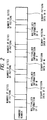
- Figs. 7 to 10 are flow charts illustrating the procedure of reading a binarization pattern registering command from the host computer, registering the binarization pattern, and selecting the registered binarization pattern (first mode) or the binarization pattern stored in the printer, to print a color image of characters, graphics or the like.
- a binarization registering command is read.
- the binarization registering pattern is analyzed at the command analysis unit 28 to register a binarization pattern.
- a pattern selection mode is selected in response to a mode selection command from the host computer 1.
- color designating information from the host computer is read, the color designating information being, for example, brightness information of designated character color R, G, B.
- a color reproduction process is executed to obtain the density information (multi-value level) of C, M, Y, and K.
- the color reproduction process includes a process of converting brightness information of R, G, and B into density information of C, M, Y, and K, a masking process of eliminating the influence of unnecessary absorption characteristics of tone or ink of C, M, and Y, a process of adjusting contrast, brightens or the like, and other processes.
- step S6 the pattern selection mode selected at step S3 is checked.
- step S7 If the registered pattern selection mode is selected (step S7), then at step S8 the registered binarization pattern 24 is selected. If the stored pattern selection mode is selected (step S10), the stored binarization pattern 25 is selected.
- the dot expand unit develops the image data into dots, respectively for C, M, Y, and K.
- a color image is outputted. The selection between the two modes may be carried out even on the same print sheet.
- step S2 will be detailed with reference to the flow chart of Fig. 8.
- step S21 a pointer is shifted to the top of the binarization pattern table for C in the binarization pattern storage 24.
- the multi-value information (e.g., a value "24" of a multi-value level including 64 levels from “0" to "63") for C is taken out from the binarization pattern registering command.
- step S23 "1" is set to a constant ⁇ .
- step S24 the constant ⁇ is compared with the multi-value information for C taken out at step S22.
- step S25 the value ⁇ and the pointer each are incremented by 1, and thereafter the control returns to step S24.
- step S26 the binarization pattern for C in the binarization pattern registering command is registered in a pattern storage area of the binarization pattern storage 24.
- step S27 the start address of the registered pattern is set to the table.
- step S28 the same processes as at steps S21 to 27 are executed for M, Y, and K.
- step S8 will be detailed with reference to the flow chart shown in Fig. 9.
- step S81 the pointer is shifted to the top of the binarization pattern table for C in the binarization pattern storage 24.
- step S82 there is taken out the multi-value information (e.g., a value "24" of the multi-value level having 64 levels from “0” to "63") obtained at step S5.
- the multi-value information e.g., a value "24" of the multi-value level having 64 levels from “0” to "63
- step S83 "1" is set to a constant ⁇ .
- step S84 the constant ⁇ is compared with the multi-value information for C taken out at step S82.
- step S85 the value ⁇ and the pointer each are incremented by 1, and thereafter the control returns to step S84.
- step S86 the start address of the binarization pattern indicated by the pointer is taken out.
- step S87 the same processes as at steps S81 to 87 are secuted for M, Y, and K.
- step S101 the pointer is shifted to the top of the binarization pattern table for C in the binarization pattern storage 25.
- step S102 there is taken out the multi-value information obtained at step S5.
- step S103 "1" is set to a constant ⁇ .
- step S104 the constant ⁇ is compared with the multi-value information for C taken out at step S102.
- step S105 the value ⁇ and the pointer each are incremented by 1, and thereafter the control returns to step S104.
- step S106 the start address of the binarization pattern indicated by the pointer is taken out.
- step S107 the same processes as at steps S101 to 106 are executed for M, Y, and K.
- this embodiment allows to register a binarization pattern inputted from the host computer.
- One of the registered pattern of the stored pattern built-in the printer is selected to print out a color image of characters, graphics or the like.
- the pattern selection mode is selected by the host computer.
- the pattern selection mode may be selected using the operating panel of the printer.
- the size of the registered binarization pattern or the built-in binarization pattern may be set arbitrarily.
- one of the registered binarization pattern or the built-in binarization pattern for each color and each multi-value level may be selectively used.
- the process time required for printing can be shortened by providing a binarization pattern previously stored. Furthermore, by providing a binarization pattern suitable for a particular printer, it becomes possible to realize a proper color reproduction. Still further, a binarization pattern is inputted from the host computer, resulting in various types of color reproduction.
- the present invention is not limited to the above embodiment, but various modifications are possible without departing from the scope of the present invention.
- a current mode may be displayed on a panel or maybe returned back to the host computer.
- An area for image printing may be designated by a particular mode.
- a particular image area such as an image edge portion may be separated to change a mode only for such an image area.
- a plurality set of binarization pattern data may be stored in ROM 25 or RAM 24 to select one of three modes or more.
Abstract
Description
- The present invention relates to an image processing apparatus suitable particularly for color printing, wherein an inputted multi-value image data is binarized to output an image such as characters, graphics, and the like.
- In a conventional printing apparatus wherein an inputted multi-value image data is binarized to output a color image such as characters, graphics, and the like, a pattern necessary for a binarization process is generated in accordance with color designating information which designates the color of a character or the like. Specifically, a host computer generates a multi-value data representative of gradations of R (red), G (green), and B (blue), or Y (yellow), M (magenta), C (cyan), and K (black), in response to color designating commands. Upon reception of the multi-value data from the host computer, the printing apparatus generates binarization patterns of Y, M, C, and K having the designated gradations, and prints out characters or the like with designated colors.
- The following disadvantages are, however, associated with the above-described related art.
- (1) A large amount of color designating information is required. For example, if a complicated color image is to be printed, it becomes necessary to designate a number of colors using a corresponding number of color designating commands, and to generate patterns as many as the number of color designating commands, taking a long time for printing the image.
- (2) Since the type of patterns to be generated are limited, it is not possible to generate optimum binarization patterns.
- It is an object of the present invention to solve the above-described problems.
- It is another object of the present invention to provide an image processing apparatus capable of providing an optimum binarization process matching the characteristics of a printing unit.
- It is a further object of the present invention to provide an image processing apparatus capable of providing a high speed binarization process.
- The above and other objects, and advantages of the present invention will become more apparent from the following detailed description and claims when read in connection with the accompanying drawings.
-
- Fig. 1 is a block diagram showing the structure of a printer according to an embodiment of the present invention;
- Fig. 2 shows an example of a binarization pattern registering command;
- Figs. 3(1) to 3(4) show examples of binarization patterns;
- Figs. 4(1) to 4(3) show examples of color characters printed by using binarization patterns;
- Fig. 5 is a binarization pattern table in a
binarization pattern storage 1; - Fig. 6 shows a binarization pattern table in a
binarization pattern storage 2; and - Figs. 7 to 10 are flow charts illustrating a procedure of printing a color image by selectively using binarization patterns registered by binarization pattern registering commands or previously stored binarization patterns.
- A preferred embodiment of the present invention will be described in detail with reference to the accompanying drawings.
- Fig. 1 is a block diagram showing the circuit arrangement of a printer according to an embodiment of the present invention.
- The
printer 2 is connected to ahost computer 1. Thehost computer 1 supplies print data, print commands, and the like to theprinter 2 which in turn prints a necessary image. - The
printer 2 has the following elements, including: aninterface 21 for data transfer to and from thehost computer 1, theinterface 21 being constituted by a microcomputer having a ROM and RAM; - a
color information storage 22 for storing information necessary for a color reproduction process; acolor reproduction unit 23 for reproducing a color; a binarization pattern storage (RAM) 24 for storing binarization patterns for a binarization process registered upon input of binarization pattern registering commands (color commands) from the host computer in accordance with color information of characters, graphics, or the like to be printed; a binarization pattern storage (ROM) 25 for storing binarization patterns already generated and built in the printer; adata bus 26; acontrol unit 27 for controlling the entirety of the printer; acommand analysis unit 28 for analyzing print data and binarization pattern registering commands supplied from thehost computer 1; a dot expandunit 29 for developing a color image data processed by a binarization pattern into dots; an output unit 30 for printing a dot-developed data on a print sheet; and anoperating panel 31 for setting and changing parameters of printing conditions. The output unit 30 prints out a color image by means of an electrophotographic method, an ink jet method, or the like. - Fig. 2 shows an example of the binarization pattern registering command (color command) sent from the host computer to the printer. The color command is constructed of density information (multi-value levels) and corresponding binarization pattern data for respective colors of C, M, Y, K. In this embodiment, for an image of 64 gradations for example, 64 color commands are used at the initial setting to sequentially output a binarization pattern for each multi-value level. After the initial setting, a pattern at a desired gradation only may be changed, or a pattern for a desired color only may be changed. The size of the pattern may be different from that of a binarization pattern stored in
ROM 25. Patterns having different sizes between colors may be registered. - In this embodiment, the pattern size is set to 8 x 8 (pixels) allowing a reproduction of 64 gradations. Such binarization patterns are provided for Y, M, C, and K, respectively.
- Fig. 4 shows printed characters "A" using the binarization patterns shown in Fig. 3. In this example, the gradations of C, M, Y, and K are designated as 100 %, 50 %, 25 %, and 0 %, respectively using the patterns shown in Figs. 3(1) to 3(4). The binarization patterns shown in Figs. 3(1) to 3(3) are developed in paint memories of C, M, and Y. The resultant character "A" has a mixed color of C, M, and Y. Since the binarization pattern for K is blank, no image is developed in the paint memory of K.
- Fig. 5 shows a binarization pattern table of the binarization pattern storage (RAM) 24. The binarization pattern table shown in Fig. 5 is prepared for each C, M, Y, and K. Each table stores pattern addresses Pi (i = 1, 2,.,., n) each represented by a pointer to a binarization pattern, the binarization pattern being prepared for each multi-value level of the density information. For example, if C has a multi-level of 64 levels (n = 64) from "0" to "63" and the value of the multi-value information of C indicates "24", then the start address of the binarization pattern for the multi-value information "24" is stored at the pattern address P24. The same is also true for M, Y, and K. The addresses may be overwritten using the binarization pattern registering command (Fig. 2) from the host computer. "-1" in the table shown in Fig. 5 represents the end of the table.
- Fig. 6 shows another binarization table in the binarization pattern storage (ROM) 25. The binarization pattern table shown in Fig. 5 is prepared for each C, M, Y, and K. Each table stores pattern addresses Qi (i = 1, 2,..., n) each represented by a pointer to a binarization pattern, the binarization pattern being prepared for each multi-value level of the density information.
- For example, if C has a multi-level of 256 levels (n = 256) from "0" to "255" and the value of the multi-value information of C indicates "24", then the start address of the binarization pattern for the multi-value information "24" is stored at the pattern address Q24. The same is also true for M, Y, and K. A pattern can be selected in accordance with the color designating information (multi-value information for C, M, Y, and K) from the host computer. "-1" in the table shown in Fig. 6 represents the end of the table.
- Figs. 7 to 10 are flow charts illustrating the procedure of reading a binarization pattern registering command from the host computer, registering the binarization pattern, and selecting the registered binarization pattern (first mode) or the binarization pattern stored in the printer, to print a color image of characters, graphics or the like.
- First, at step S1, a binarization registering command is read. At step S2 the binarization registering pattern is analyzed at the
command analysis unit 28 to register a binarization pattern. - At step S3 a pattern selection mode is selected in response to a mode selection command from the
host computer 1. - At step S4 color designating information from the host computer is read, the color designating information being, for example, brightness information of designated character color R, G, B.
- At step S5 a color reproduction process is executed to obtain the density information (multi-value level) of C, M, Y, and K. The color reproduction process includes a process of converting brightness information of R, G, and B into density information of C, M, Y, and K, a masking process of eliminating the influence of unnecessary absorption characteristics of tone or ink of C, M, and Y, a process of adjusting contrast, brightens or the like, and other processes.
- At step S6, the pattern selection mode selected at step S3 is checked.
- If the registered pattern selection mode is selected (step S7), then at step S8 the registered
binarization pattern 24 is selected. If the stored pattern selection mode is selected (step S10), thestored binarization pattern 25 is selected. - At step S11, in accordance with the binarization pattern selected at step S8 or S10, the dot expand unit develops the image data into dots, respectively for C, M, Y, and K. At step S12, a color image is outputted. The selection between the two modes may be carried out even on the same print sheet.
- The process at step S2 will be detailed with reference to the flow chart of Fig. 8.
- First, at step S21 a pointer is shifted to the top of the binarization pattern table for C in the
binarization pattern storage 24. - At step S22 the multi-value information (e.g., a value "24" of a multi-value level including 64 levels from "0" to "63") for C is taken out from the binarization pattern registering command.
- At step S23 "1" is set to a constant α.
- At step S24 the constant α is compared with the multi-value information for C taken out at step S22.
- If the both values are not equal, at step S25 the value α and the pointer each are incremented by 1, and thereafter the control returns to step S24.
- If the both values are equal, at step S26 the binarization pattern for C in the binarization pattern registering command is registered in a pattern storage area of the
binarization pattern storage 24. At step S27, the start address of the registered pattern is set to the table. At step S28, the same processes as at steps S21 to 27 are executed for M, Y, and K. - The process at step S8 will be detailed with reference to the flow chart shown in Fig. 9.
- First, at step S81 the pointer is shifted to the top of the binarization pattern table for C in the
binarization pattern storage 24. - At step S82 there is taken out the multi-value information (e.g., a value "24" of the multi-value level having 64 levels from "0" to "63") obtained at step S5.
- At step S83 "1" is set to a constant α.
- At step S84 the constant α is compared with the multi-value information for C taken out at step S82.
- If the both values are not equal, at step S85 the value α and the pointer each are incremented by 1, and thereafter the control returns to step S84.
- If the both values are equal, at step S86 the start address of the binarization pattern indicated by the pointer is taken out.
- At step S87, the same processes as at steps S81 to 87 are secuted for M, Y, and K.
- Next, the process at step S10 will be detailed with reference to the flow chart shown in Fig. 10.
- First, at step S101 the pointer is shifted to the top of the binarization pattern table for C in the
binarization pattern storage 25. - At step S102 there is taken out the multi-value information obtained at step S5.
- At step S103 "1" is set to a constant α.
- At step S104 the constant α is compared with the multi-value information for C taken out at step S102.
- If the both values are not equal, at step S105 the value α and the pointer each are incremented by 1, and thereafter the control returns to step S104.
- If the both values are equal, at step S106 the start address of the binarization pattern indicated by the pointer is taken out.
- At step S107, the same processes as at steps S101 to 106 are executed for M, Y, and K.
- As described so far, this embodiment allows to register a binarization pattern inputted from the host computer. One of the registered pattern of the stored pattern built-in the printer is selected to print out a color image of characters, graphics or the like.
- In the above-described embodiment, the pattern selection mode is selected by the host computer. The pattern selection mode may be selected using the operating panel of the printer.
- In the above embodiment, the size of the registered binarization pattern or the built-in binarization pattern may be set arbitrarily.
- Furthermore, one of the registered binarization pattern or the built-in binarization pattern for each color and each multi-value level may be selectively used.
- As appreciated from the foregoing description of the present invention, the process time required for printing can be shortened by providing a binarization pattern previously stored. Furthermore, by providing a binarization pattern suitable for a particular printer, it becomes possible to realize a proper color reproduction. Still further, a binarization pattern is inputted from the host computer, resulting in various types of color reproduction.
- The present invention is not limited to the above embodiment, but various modifications are possible without departing from the scope of the present invention. For example, in a test printing, the same multi-value data may be printed on the same print sheet using the two modes. A current mode may be displayed on a panel or maybe returned back to the host computer. An area for image printing may be designated by a particular mode. A particular image area such as an image edge portion may be separated to change a mode only for such an image area. A plurality set of binarization pattern data may be stored in
ROM 25 orRAM 24 to select one of three modes or more.
Claims (25)
- An image processing apparatus having a process of binarizing a multi-value image data comprising:
means for inputting a multi-value image data and first pattern information for a binarization process;
first storage means for storing said first pattern information; and
binarizing means for binarizing said inputted multi-value image data using said first pattern information stored in said first storage means. - An apparatus according to claim 1, further comprising second storage means for storing in advance second pattern information, wherein said apparatus has a first mode during which said inputted multi-value image data is binarized using said first pattern information, and a second mode during which said inputted multi-value image data is binarized using said second pattern information.
- An apparatus according to claim 2, wherein said second storage means is a ROM.
- An apparatus according to claim 1, wherein said first and second pattern information includes patterns in correspondence with the gradations represented by said multi-value image data.
- An apparatus according to claim 4, wherein said binarizing means reads a pattern corresponding to a gradation represented by said inputted multi-value image data from said first or second storage means.
- An apparatus according to claim 2, further comprising selecting means for selecting one of said first and second modes.
- An apparatus according to claim 6, wherein said selecting means manually selects one of said first and second modes.
- An apparatus according to claim 6, wherein said selecting means selects one of said first and second modes in accordance with an external command.
- An apparatus according to claim 2, wherein in a test printing said apparatus prints the same multi-value image data on the same print sheet using both said first and second modes.
- An apparatus according to claim 2, wherein said first storage means stores said first pattern information having a pattern size different from that of said second pattern information stored in said second storage means.
- An apparatus according to claim 2, further comprising display means for displaying a current mode.
- An apparatus according to claim 2, wherein said apparatus prints an image on a predetermined area of a print sheet in a particular mode.
- An apparatus according to claim 12, wherein said predetermined area or said specific mode is designated by an operator.
- An apparatus according to claim 12, further comprising means for detecting, as said predetermined area, an edge portion of an image to be printed.
- An apparatus according to claim 1, wherein said apparatus is a color image processing apparatus, and said first storage means stores said pattern information of a plurality of colors.
- An apparatus according to claim 1, wherein said apparatus stores said first pattern information having a pattern size different from each color.
- A printing apparatus for printing a multi-value image supplied from an external apparatus by binarizing the multi-value image data, comprising:
a RAM for storing first pattern information including a first binarization pattern corresponding to each gradation of said multi-value image data, said first pattern information being supplied from said external apparatus; and
a ROM for storing in advance second pattern information including a second binarization pattern corresponding to each value of said multi-value image data,
wherein said apparatus includes a first mode during which said apparatus prints an image by reading said first binarization pattern corresponding to a value of said multi-value image data supplied from said external apparatus and a second mode during which said apparatus prints an image by reading said second binarization pattern. - An apparatus according to claim 17, wherein said apparatus is a color printer, and at least said RAM stores said first pattern information different for each color.
- An apparatus according to claim 18, wherein said RAM stores said first pattern information having a pattern size different for each color.
- Apparatus for printing predetermined patterns, comprising means for generating an array of multi-bit pixels defining an image, and means for processing said multi-bit pixels to produce a binarised image, said processing means being arranged to execute either dither matrix processing or error diffusion matrix processing, in accordance with a predetermined binarisation matrix, characterised in that it includes means for storing predetermined binarisation matrices corresponding to predetermined patterns to be printed.
- Apparatus according to claim 20, further comprising means for storing a default binarisation matrix, and means for selecting between said predetermined stored matrices and said default matrix.
- A colour printer including binarisation matrix processing means for binarising multi-bit image data, characterised in that said processing means is arranged to binarise different coloured data differently.
- A method of printing predetermined characters on a printer having a predetermined number of output density levels, comprising generating image data in a higher number of output levels and quantising said image data to said predetermined number of output levels for printing, characterised in that said quantisation is performed in dependence upon the identity of an image portion (e.g. character) to be printed, so as to optimise said quantisation.
- An apparatus according to claim 6, wherein said selecting means selects said second mode when the first pattern information is stored in the first storage means.
- A printing apparatus according to claim 17, further comprising means for selecting either one of first and second modes, wherein said selection means selects said second mode when the first pattern information is stored in said RAM.
Applications Claiming Priority (2)
| Application Number | Priority Date | Filing Date | Title |
|---|---|---|---|
| JP2206551A JPH0490669A (en) | 1990-08-03 | 1990-08-03 | Printer |
| JP206551/90 | 1990-08-03 |
Publications (3)
| Publication Number | Publication Date |
|---|---|
| EP0469882A2 true EP0469882A2 (en) | 1992-02-05 |
| EP0469882A3 EP0469882A3 (en) | 1993-02-24 |
| EP0469882B1 EP0469882B1 (en) | 1996-11-20 |
Family
ID=16525263
Family Applications (1)
| Application Number | Title | Priority Date | Filing Date |
|---|---|---|---|
| EP91307010A Expired - Lifetime EP0469882B1 (en) | 1990-08-03 | 1991-07-31 | Image processing apparatus |
Country Status (4)
| Country | Link |
|---|---|
| US (1) | US5475496A (en) |
| EP (1) | EP0469882B1 (en) |
| JP (1) | JPH0490669A (en) |
| DE (1) | DE69123196T2 (en) |
Cited By (4)
| Publication number | Priority date | Publication date | Assignee | Title |
|---|---|---|---|---|
| EP0586080A2 (en) * | 1992-07-31 | 1994-03-09 | Canon Kabushiki Kaisha | Image processing method and apparatus |
| EP0592769A1 (en) * | 1992-10-13 | 1994-04-20 | Hewlett-Packard Company | Method to convert bitmaps to monochrome data |
| US6359695B1 (en) | 1992-02-26 | 2002-03-19 | Canon Kabushiki Kaisha | Repeated image forming apparatus with neighboring image boundary gradiation correction |
| US6433884B1 (en) * | 1993-10-29 | 2002-08-13 | Ricoh Company, Ltd. | Apparatus for determining priority of print jobs in a printer system |
Families Citing this family (7)
| Publication number | Priority date | Publication date | Assignee | Title |
|---|---|---|---|---|
| JP2897599B2 (en) * | 1993-06-23 | 1999-05-31 | 松下電器産業株式会社 | Image forming device |
| JP3335009B2 (en) * | 1994-09-08 | 2002-10-15 | キヤノン株式会社 | Image processing method and image processing apparatus |
| US5726778A (en) * | 1994-09-16 | 1998-03-10 | Canon Kabushiki Kaisha | Image processing apparatus with color-space conversion |
| JP3359234B2 (en) * | 1996-07-31 | 2002-12-24 | キヤノン株式会社 | Image processing apparatus and method |
| JP2003046783A (en) * | 2001-08-02 | 2003-02-14 | Fujitsu Ltd | Smoothing method and smoothing circuit |
| JP3994984B2 (en) * | 2004-05-06 | 2007-10-24 | コニカミノルタビジネステクノロジーズ株式会社 | Print support module, recording medium, and print job issuing method |
| US10922801B2 (en) | 2017-07-19 | 2021-02-16 | Lockheed Martin Corporation | Channel-based binarization of color |
Citations (6)
| Publication number | Priority date | Publication date | Assignee | Title |
|---|---|---|---|---|
| DE1597773A1 (en) * | 1967-08-26 | 1970-05-06 | Hell Rudolf Dr Ing Fa | Process for setting rastered halftone images by means of electronic light setting devices that work according to the raster process |
| US4004079A (en) * | 1975-11-14 | 1977-01-18 | Optronics International, Inc. | Method and apparatus for dual resolution photographic reproduction of line and continuous tone graphic materials |
| US4005475A (en) * | 1972-06-02 | 1977-01-25 | Dr. -Ing. Rudolf Hell Gmbh | Method for improving sharpness when recording half-tone pictures by modulating a sharpness signal |
| US4084196A (en) * | 1977-01-31 | 1978-04-11 | Dacom, Inc. | Electronic half-tone generating means for facsimile reproduction system |
| GB2117208A (en) * | 1982-03-13 | 1983-10-05 | Dainippon Screen Mfg | Reproducing composite picture from scanned original picture and scanned character document |
| US4918622A (en) * | 1988-11-16 | 1990-04-17 | Eastman Kodak Company | Electronic graphic arts screener |
Family Cites Families (9)
| Publication number | Priority date | Publication date | Assignee | Title |
|---|---|---|---|---|
| JPS59161981A (en) * | 1983-03-06 | 1984-09-12 | Canon Inc | Picture processor |
| FR2542540B1 (en) * | 1983-03-08 | 1989-02-10 | Canon Kk | IMAGE PROCESSING SYSTEM |
| DE3444366C3 (en) * | 1983-12-09 | 1994-12-22 | Canon Kk | Image processing device |
| US4724446A (en) * | 1985-01-31 | 1988-02-09 | Kabushiki Kaisha Toshiba | Thermal transfer printing apparatus |
| JPS63296952A (en) * | 1987-05-29 | 1988-12-05 | Ricoh Co Ltd | Printer |
| JP2774501B2 (en) * | 1987-11-05 | 1998-07-09 | 株式会社リコー | Multi-level gradation processing method for color image |
| US5038208A (en) * | 1987-11-16 | 1991-08-06 | Canon Kabushiki Kaisha | Image forming apparatus with a function for correcting recording density uneveness |
| US4878063A (en) * | 1988-12-05 | 1989-10-31 | Eastman Kodak Company | Multicolor printing apparatus and method having vernier detection/correction system for adjusting color separation planes |
| US5105266A (en) * | 1989-11-30 | 1992-04-14 | Eastman Kodak Company | Single pass color substitution |
-
1990
- 1990-08-03 JP JP2206551A patent/JPH0490669A/en active Pending
-
1991
- 1991-07-31 EP EP91307010A patent/EP0469882B1/en not_active Expired - Lifetime
- 1991-07-31 DE DE69123196T patent/DE69123196T2/en not_active Expired - Fee Related
-
1993
- 1993-08-23 US US08/110,767 patent/US5475496A/en not_active Expired - Lifetime
Patent Citations (6)
| Publication number | Priority date | Publication date | Assignee | Title |
|---|---|---|---|---|
| DE1597773A1 (en) * | 1967-08-26 | 1970-05-06 | Hell Rudolf Dr Ing Fa | Process for setting rastered halftone images by means of electronic light setting devices that work according to the raster process |
| US4005475A (en) * | 1972-06-02 | 1977-01-25 | Dr. -Ing. Rudolf Hell Gmbh | Method for improving sharpness when recording half-tone pictures by modulating a sharpness signal |
| US4004079A (en) * | 1975-11-14 | 1977-01-18 | Optronics International, Inc. | Method and apparatus for dual resolution photographic reproduction of line and continuous tone graphic materials |
| US4084196A (en) * | 1977-01-31 | 1978-04-11 | Dacom, Inc. | Electronic half-tone generating means for facsimile reproduction system |
| GB2117208A (en) * | 1982-03-13 | 1983-10-05 | Dainippon Screen Mfg | Reproducing composite picture from scanned original picture and scanned character document |
| US4918622A (en) * | 1988-11-16 | 1990-04-17 | Eastman Kodak Company | Electronic graphic arts screener |
Non-Patent Citations (2)
| Title |
|---|
| IBM JOURNAL OF RESEARCH AND DEVELOPMENT vol. 31, no. 1, January 1987, NEW YORK US pages 2 - 15 G. GOERTZEL ET AL. 'Digital halftoning on the IBM 4250 Printer' * |
| RCA REVIEW, vol. 31, no. 3, September 1970, PRINCETON (US) pages 517 - 533 R.J. KLENSCH ET AL. 'Electronically Generated Halftone Pictures' * |
Cited By (11)
| Publication number | Priority date | Publication date | Assignee | Title |
|---|---|---|---|---|
| US6359695B1 (en) | 1992-02-26 | 2002-03-19 | Canon Kabushiki Kaisha | Repeated image forming apparatus with neighboring image boundary gradiation correction |
| US6486966B1 (en) | 1992-02-26 | 2002-11-26 | Canon Kabushiki Kaisha | Image forming apparatus for forming images with primary and secondary image data |
| US6490053B1 (en) | 1992-02-26 | 2002-12-03 | Canon Kabushiki Kaisha | Image supply apparatus, image output apparatus, control apparatus therefor, and image forming apparatus incorporating them |
| EP0944023B1 (en) * | 1992-02-26 | 2003-05-07 | Canon Kabushiki Kaisha | Image supply apparatus, image output apparatus, control apparatus therefore, and image forming apparatus incorporating them |
| US7187467B2 (en) | 1992-02-26 | 2007-03-06 | Canon Kabushiki Kaisha | Image supply apparatus, image output apparatus, control apparatus therefor, and image forming apparatus incorporating them |
| EP0586080A2 (en) * | 1992-07-31 | 1994-03-09 | Canon Kabushiki Kaisha | Image processing method and apparatus |
| EP0586080A3 (en) * | 1992-07-31 | 1994-03-30 | Canon Kabushiki Kaisha | Image processing method and apparatus |
| US6331897B1 (en) | 1992-07-31 | 2001-12-18 | Canon Kabushiki Kaisha | Image processing method and apparatus in which a table stores by a scan line unit memory addresses at each of which a function is stored for developing an image for one line into a memory |
| EP0592769A1 (en) * | 1992-10-13 | 1994-04-20 | Hewlett-Packard Company | Method to convert bitmaps to monochrome data |
| US5457772A (en) * | 1992-10-13 | 1995-10-10 | Hewlett-Packard Company | Method to convert bitmaps to monochrome data |
| US6433884B1 (en) * | 1993-10-29 | 2002-08-13 | Ricoh Company, Ltd. | Apparatus for determining priority of print jobs in a printer system |
Also Published As
| Publication number | Publication date |
|---|---|
| DE69123196D1 (en) | 1997-01-02 |
| US5475496A (en) | 1995-12-12 |
| EP0469882B1 (en) | 1996-11-20 |
| EP0469882A3 (en) | 1993-02-24 |
| JPH0490669A (en) | 1992-03-24 |
| DE69123196T2 (en) | 1997-04-03 |
Similar Documents
| Publication | Publication Date | Title |
|---|---|---|
| US6975418B1 (en) | Copying machine, image processing apparatus, image processing system and image processing method | |
| US6331042B1 (en) | System for calibrating image processing characteristics of a printer | |
| CN101169709B (en) | Print control apparatus and print control method | |
| EP0469882A2 (en) | Image processing apparatus | |
| EP0457572B1 (en) | Outputting method and apparatus | |
| EP0783226B1 (en) | Image processing apparatus and method | |
| EP0484900B1 (en) | Method and apparatus for changing the colour density in a printer | |
| US6351263B1 (en) | Image processor which manually and independently designates processing parameters for character data and image data | |
| EP0473389B1 (en) | Image processing method and apparatus | |
| US5295239A (en) | Printing color control in color printing apparatus | |
| US5051820A (en) | Color image recording apparatus capable of recording color gradation pattern | |
| EP0582421B1 (en) | Image processing apparatus | |
| JP2911539B2 (en) | Recording device | |
| JPH10138567A (en) | Apparatus for setting color of character | |
| US5123083A (en) | Video hard copy with setting printing condition | |
| JPH1024624A (en) | Color printer | |
| JP2002166603A (en) | Print processing method | |
| JPS62150478A (en) | Picture information processor | |
| JP2001186322A (en) | Patch chart and picture processor | |
| EP0464677B1 (en) | Method of setting a printing condition of a video hardcopy | |
| JPH0787318A (en) | Image processor and image forming device | |
| JP3513198B2 (en) | Print processing apparatus, print processing method, and printing apparatus | |
| JP3149877B2 (en) | Color printer controller | |
| JPH0217767A (en) | Digital color copying machine | |
| JPH08116463A (en) | Image processing unit |
Legal Events
| Date | Code | Title | Description |
|---|---|---|---|
| PUAI | Public reference made under article 153(3) epc to a published international application that has entered the european phase |
Free format text: ORIGINAL CODE: 0009012 |
|
| AK | Designated contracting states |
Kind code of ref document: A2 Designated state(s): DE FR GB |
|
| PUAL | Search report despatched |
Free format text: ORIGINAL CODE: 0009013 |
|
| AK | Designated contracting states |
Kind code of ref document: A3 Designated state(s): DE FR GB |
|
| 17P | Request for examination filed |
Effective date: 19930709 |
|
| 17Q | First examination report despatched |
Effective date: 19950508 |
|
| GRAG | Despatch of communication of intention to grant |
Free format text: ORIGINAL CODE: EPIDOS AGRA |
|
| GRAH | Despatch of communication of intention to grant a patent |
Free format text: ORIGINAL CODE: EPIDOS IGRA |
|
| GRAH | Despatch of communication of intention to grant a patent |
Free format text: ORIGINAL CODE: EPIDOS IGRA |
|
| GRAA | (expected) grant |
Free format text: ORIGINAL CODE: 0009210 |
|
| AK | Designated contracting states |
Kind code of ref document: B1 Designated state(s): DE FR GB |
|
| REF | Corresponds to: |
Ref document number: 69123196 Country of ref document: DE Date of ref document: 19970102 |
|
| ET | Fr: translation filed | ||
| PLBE | No opposition filed within time limit |
Free format text: ORIGINAL CODE: 0009261 |
|
| STAA | Information on the status of an ep patent application or granted ep patent |
Free format text: STATUS: NO OPPOSITION FILED WITHIN TIME LIMIT |
|
| 26N | No opposition filed | ||
| REG | Reference to a national code |
Ref country code: GB Ref legal event code: IF02 |
|
| PGFP | Annual fee paid to national office [announced via postgrant information from national office to epo] |
Ref country code: FR Payment date: 20090722 Year of fee payment: 19 |
|
| PGFP | Annual fee paid to national office [announced via postgrant information from national office to epo] |
Ref country code: DE Payment date: 20090731 Year of fee payment: 19 Ref country code: GB Payment date: 20090731 Year of fee payment: 19 |
|
| GBPC | Gb: european patent ceased through non-payment of renewal fee |
Effective date: 20100731 |
|
| REG | Reference to a national code |
Ref country code: FR Ref legal event code: ST Effective date: 20110331 |
|
| PG25 | Lapsed in a contracting state [announced via postgrant information from national office to epo] |
Ref country code: DE Free format text: LAPSE BECAUSE OF NON-PAYMENT OF DUE FEES Effective date: 20110201 |
|
| REG | Reference to a national code |
Ref country code: DE Ref legal event code: R119 Ref document number: 69123196 Country of ref document: DE Effective date: 20110201 |
|
| PG25 | Lapsed in a contracting state [announced via postgrant information from national office to epo] |
Ref country code: FR Free format text: LAPSE BECAUSE OF NON-PAYMENT OF DUE FEES Effective date: 20100802 |
|
| PG25 | Lapsed in a contracting state [announced via postgrant information from national office to epo] |
Ref country code: GB Free format text: LAPSE BECAUSE OF NON-PAYMENT OF DUE FEES Effective date: 20100731 |