EP0469769A2 - Magnetically-coupled, two-resonant-circuit, frequency-division tag - Google Patents
Magnetically-coupled, two-resonant-circuit, frequency-division tag Download PDFInfo
- Publication number
- EP0469769A2 EP0469769A2 EP91306658A EP91306658A EP0469769A2 EP 0469769 A2 EP0469769 A2 EP 0469769A2 EP 91306658 A EP91306658 A EP 91306658A EP 91306658 A EP91306658 A EP 91306658A EP 0469769 A2 EP0469769 A2 EP 0469769A2
- Authority
- EP
- European Patent Office
- Prior art keywords
- circuit
- frequency
- resonant
- electromagnetic radiation
- frequency divider
- Prior art date
- Legal status (The legal status is an assumption and is not a legal conclusion. Google has not performed a legal analysis and makes no representation as to the accuracy of the status listed.)
- Granted
Links
Images

Classifications
-
- G—PHYSICS
- G08—SIGNALLING
- G08B—SIGNALLING OR CALLING SYSTEMS; ORDER TELEGRAPHS; ALARM SYSTEMS
- G08B13/00—Burglar, theft or intruder alarms
- G08B13/22—Electrical actuation
- G08B13/24—Electrical actuation by interference with electromagnetic field distribution
- G08B13/2402—Electronic Article Surveillance [EAS], i.e. systems using tags for detecting removal of a tagged item from a secure area, e.g. tags for detecting shoplifting
- G08B13/2405—Electronic Article Surveillance [EAS], i.e. systems using tags for detecting removal of a tagged item from a secure area, e.g. tags for detecting shoplifting characterised by the tag technology used
- G08B13/2414—Electronic Article Surveillance [EAS], i.e. systems using tags for detecting removal of a tagged item from a secure area, e.g. tags for detecting shoplifting characterised by the tag technology used using inductive tags
- G08B13/242—Tag deactivation
-
- G—PHYSICS
- G08—SIGNALLING
- G08B—SIGNALLING OR CALLING SYSTEMS; ORDER TELEGRAPHS; ALARM SYSTEMS
- G08B13/00—Burglar, theft or intruder alarms
- G08B13/22—Electrical actuation
- G08B13/24—Electrical actuation by interference with electromagnetic field distribution
- G08B13/2402—Electronic Article Surveillance [EAS], i.e. systems using tags for detecting removal of a tagged item from a secure area, e.g. tags for detecting shoplifting
- G08B13/2405—Electronic Article Surveillance [EAS], i.e. systems using tags for detecting removal of a tagged item from a secure area, e.g. tags for detecting shoplifting characterised by the tag technology used
- G08B13/2422—Electronic Article Surveillance [EAS], i.e. systems using tags for detecting removal of a tagged item from a secure area, e.g. tags for detecting shoplifting characterised by the tag technology used using acoustic or microwave tags
- G08B13/2425—Tag deactivation
-
- G—PHYSICS
- G08—SIGNALLING
- G08B—SIGNALLING OR CALLING SYSTEMS; ORDER TELEGRAPHS; ALARM SYSTEMS
- G08B13/00—Burglar, theft or intruder alarms
- G08B13/22—Electrical actuation
- G08B13/24—Electrical actuation by interference with electromagnetic field distribution
- G08B13/2402—Electronic Article Surveillance [EAS], i.e. systems using tags for detecting removal of a tagged item from a secure area, e.g. tags for detecting shoplifting
- G08B13/2428—Tag details
- G08B13/2431—Tag circuit details
-
- G—PHYSICS
- G08—SIGNALLING
- G08B—SIGNALLING OR CALLING SYSTEMS; ORDER TELEGRAPHS; ALARM SYSTEMS
- G08B13/00—Burglar, theft or intruder alarms
- G08B13/22—Electrical actuation
- G08B13/24—Electrical actuation by interference with electromagnetic field distribution
- G08B13/2402—Electronic Article Surveillance [EAS], i.e. systems using tags for detecting removal of a tagged item from a secure area, e.g. tags for detecting shoplifting
- G08B13/2428—Tag details
- G08B13/2437—Tag layered structure, processes for making layered tags
- G08B13/2442—Tag materials and material properties thereof, e.g. magnetic material details
Definitions
- the present invention generally pertains to frequency dividers and is particularly directed to portable, batteryless, frequency dividers of type that are included in tags that are used in presence detection systems.
- the frequency divider described in the '428 patent includes a resonant first circuit that is resonant at a first frequency for receiving electromagnetic radiation at the first frequency, and a second resonant circuit that is resonant at a second frequency that is one-half the first frequency for transmitting electromagnetic radiation at the second frequency; and the two resonant circuits are electrically connected to one another by a semiconductor switching device having gain coupling the first and second resonant circuits for causing the second circuit to transmit electromagnetic radiation at the second frequency solely in response to unrectified energy at the first frequency provided in the first circuit upon receipt of electromagnetic radiation at the first frequency.
- Each resonant circuit includes a fixed capacitance connected in parallel with an inductance coil.
- this frequency divider that utilizes an air core coil for the first resonant circuit and a ferrite core coil for the second resonant circuit, the inside diameter of the air core coil is much larger than the diameter of the ferrite core coil to further minimize the magnetic coupling between the coils.
- the frequency divider described in the '740 patent consists of a single resonant circuit consisting of an inductor and a diode or varactor connected in parallel with the diode or varactor to define a resonant circuit that detects electromagnetic radiation at a first predetermined frequency and responds to said detection by transmitting electromagnetic radiation at a second frequency that is one-half the first frequency, wherein the circuit is resonant at the second frequency when the voltage across the diode or varactor is zero.
- the frequency divider described in the '740 patent is less comply than the frequency divider described in the '428 patent, whereby the former may be manufactured less expensively and packaged more compactly in a tag for attachment to an article to be detected by a presence detection system, the former also is less efficient in initiating frequency division from the energy of the detected electromagnetic radiation, since the frequency divider circuit is resonant at only the second frequency.
- the present invention provides a frequency divider that is less complex and expensive to manufacture and that may be packaged more compactly than the frequency divider described in the '428 patent without a significant decrease in performance.
- a batteryless, portable, frequency divider includes a first resonant circuit that is resonant at a first frequency for receiving electromagnetic radiation at the first frequency; and a second resonant circuit that is resonant at a second frequency that is one-half the first frequency for transmitting electromagnetic radiation at the second frequency; wherein the first circuit is coupled only magnetically to the second circuit to transfer energy to the second circuit at the first frequency in response to receipt by the first circuit of electromagnetic radiation at the first frequency; and wherein the second circuit includes a variable reactance element in which the reactance varies with variations in energy transferred from the first circuit for causing the second circuit to transmit electromagnetic radiation at the second frequency in response to the energy transferred from the first circuit at the first frequency.
- a batteryless, portable, frequency divider includes a first resonant circuit that is resonant at a first frequency for receiving electromagnetic radiation at the first frequency; and a second resonant circuit that is resonant at a second frequency that is one-half the first frequency for transmitting electromagnetic radiation at the second frequency; wherein the first circuit is coupled only magnetically to the second circuit to transfer energy to the second circuit in response to receipt by the first circuit of electromagnetic radiation at the first frequency; and wherein the first circuit includes a variable reactance element in which the reactance varies with variations in energy received by the first circuit for causing the second circuit to vary in reactance due to mutual reactive coupling to cause the second circuit to transmit electromagnetic radiation at the second frequency in response to the energy transferred from the first circuit at the first frequency.
- the second circuit includes a variable reactance element in which the reactance varies with variations in energy transferred from the first circuit for causing the second circuit to transmit electromagnetic radiation at the second frequency in response to the energy transferred from the first circuit at the first frequency.
- each circuit includes a capacitance and an inductance coil, with the coins being disposed on magnetic circuit means for enhancing said magnetic coupling.
- the present invention also provides a tag including the frequency divider of the present invention and a presence detection system including such tag.
- a preferred embodiment of a frequency divider includes a first resonant circuit 10 consisting of a capacitor C1 connected in parallel with an inductance coil L1 wound about a straight ferrite rod 12; and a second resonant circuit 14 consisting of a variable capacitance diode or varactor D2 connected in parallel with a second inductance coil L2 that is also wound about the ferrite rod 12.
- the first resonant circuit 10 is resonant at a first frequency f 1 for receiving electromagnetic radiation at the first frequency f i ; and the second resonant circuit 14 is resonant at a second frequency f 2 that is one-half the first frequency f 1 for transmitting electromagnetic radiation at the second frequency f 2 .
- the first circuit 10 is coupled only magnetically by the ferrite rod 12 and air to the second circuit 14 to transfer energy to the second circuit 14 at the first frequency f 1 in response to receipt by the first circuit 10 of electromagnetic radiation at the first frequency f 1 .
- variable capacitance diode or varactor D2 in the second circuit 14 is a variable reactance element in which the reactance varies with variations in energy transferred from the first circuit 10 for causing the second circuit 14 to transmit electromagnetic radiation at the second frequency f 2 in response to the energy transferred from the first circuit 10 at the first frequency f, .
- the coil L1 of the first resonant circuit 10 enhances the electromagnetic radiation at the first frequency f 1 that is induced in the coil L2 of the second resonant circuit 14, and thereby decreases the required field strength of electromagnetic radiation at the first frequency f 1 necessary for accomplishing frequency division.
- the resonant circuits 10, 14 are tuned to their respective resonant frequencies f 1 and f 2 by adjusting the positions of the coils L1 and L2 on the rod 12.
- the coils L1, L2 are wound with an inside dimension d' that is somewhat larger than the the cross-sectional dimension d" of the ferrite rod 12.
- the coils L1, L2 are wound on a non-magnetic spacing element 16 that is adjustably mounted on the ferrite rod 12.
- the rod 12 has a diameter d" of approximately 0.125 inch (0.31 cm.); and the coils L1, L2 each have an inside diameter of approximately 0.15 inch (0.38 cm.).
- the coupling coefficient "k" between the inductance coil L1 of the first resonant circuit 10 and the inductance coil L2 of the second resonant circuit 14 should be within a range of zero to 0.6; and that conversion of the energy of electromagnetic radiation at the first resonant frequency f 1 received by the first resonant circuit 10 into electromagnetic radiation radiated by the second resonant circuit 14 at the second frequency f 2 is most efficient when the coupling coefficient k is about 0.3.
- the coils L1 and L2 are wound on opposite ends of a 1.25 inch (3.2 cm.) long straight ferrite rod 12 having a diameter of 0.125 inch (0.3 cm.).
- Each coil L1, L2 is approximately 0.375 inch (0.95 cm.) long, with the ends of the coils L1, L2 adjacent the respective ends of the rod 12 being positioned ⁇ 0.125 inch from the ends of the rod 12.
- the coils should be at least 0.375 inch apart to prevent such interactive coupling as would make tuning of both resonant circuits 10, 14 difficult.
- Each coil L1, L2 should not be longer than approximately 35 percent of the length of the rod 12.
- the frequency divider of this example is activated at signal levels that are several orders of magnitude below those of prior art frequency dividers of similar size. Even more important the frequency division efficiency of this frequency divider as determined by its energy transfer function is very high, thereby enabling transmission of electromagnetic radiation at the frequency-divided second resonant frequency f 2 having the same order of magnitude as provided by prior art frequency dividers that are many times larger.
- the capacitance C1 is a 680 pico-farad capacitor and the diode or varactor D1 has a varactor junction capacitance of approximately 600 pico-farads.
- a variable capacitance diode or varactor D1 which has one or a plurality of parallel varactor junctions that exhibit a large and nonlinear change in capacitance with small levels of applied alternating voltage, such as a zener diode, is utilized as the voltage-responsive-variable-reactance element in the second resonant circuit 14 because of its low cost.
- some other device exhibiting the required large and nonlinear capacitance variation with applied alternating voltage, and having sufficiently low loss, and a high Q factor, could be substituted for a variable capacitance diode or varactor.
- Low-magnetic-loss ferromagnetic materials other than ferrite can be utilized in the rod 12 of the magnetic circuit means.
- the magnetic circuit means used to couple the coils of the different resonant circuits is merely air.
- This embodiment is the least complex; and adequate magnetic coupling can be attained to provide a presence detection tag that is practical for some applications by disposing the coils in close proximity to one another.
- this embodiment may be more difficult to tune to the respective resonant frequencies in the absence of a ferrite core which enables fine adjustments of the resonant frequencies by adjustment of the positions of coils on the core, as discussed above.
- the magnetic circuit means for coupling the coils of the different resonant circuits are ferrite elements having configurations other than that of a straight rod.
- the orientation of the response of a tag containing the frequency divider may be tailored to specific applications and configurations of exciting electromagnetic fields at the first resonant frequency f 1 .
- the magnetic circuit means includes an L-shaped ferrite element 20.
- the frequency divider includes a first resonant circuit 22 consisting of a capacitor C1' connected in parallel with an inductance coil L1' wound about one end of the L-shaped ferrite element 20; and a second resonant circuit 24 consisting of a variable capacitance diode or varactor D2' connected in parallel with a second inductance coil L2' that is wound about the other end of the L-shaped ferrite element 20.
- the construction of the frequency divider of Figure 2 is subject to the conditions stated above with respect to the construction of the frequency divider of Figure 1, such that the operation of the frequency divider of Figure 2 is the same as the operation of the frequency divider of Figure 1.
- the frequency divider includes a first resonant circuit 32 consisting of a capacitor C1" connected in parallel with an inductance coil L 1" wound about one end of the ferrite element 30; and a second resonant circuit 34 consisting of a variable capacitance diode or varactor D2" connected in parallel with a second inductance coil L2" that is wound about the other end of the ferrite element 30.
- the construction of the frequency divider of Figure 3 is subject to the conditions stated above with respect to the construction of the frequency divider of Figure 1, such that the operation of the frequency divider of Figure 3 is the same as the operation of the frequency divider of Figure 1.
- the magnetic circuit means may include two or more separate ferrite rods that are closely magnetically coupled to each other to optimize performance and/or provide a magnetic circuit with a larger aperture than can be achieved with a single ferrite rod of the maximum manufacturable length.
- ferrite rods cannot be cheaply manufactured with length-to-diameter ratios greater than ten or twelve. By disposing a plurality of straight ferrite rods end to end, the aperture of the magnetic circuit can be enlarged.
- the interactive magnetic coupling between the coils is decreased by decreasing the reluctance between the coils, thereby making the separate resonant circuits easier to tune by adjusting the positions of the coils on the rods.
- the magnetic circuit means include two straight ferromagnetic rods 40, 42 disposed end to end with an air gap 44 therebetween.
- the frequency divider includes a first resonant circuit 46 consisting of a capacitor C1 "' connected in parallel with an inductance coil L1 "' wound about one of the ferrite rods 40; and a second resonant circuit 48 consisting of a variable capacitance diode or varactor D2"' connected in parallel with a second inductance coil L2'" that is wound about the other of the ferrite rods 42.
- the construction of the frequency divider of Figure 2 is subject to the conditions stated above with respect to the construction of the frequency divider of Figure 1, such that the operation of the frequency divider of Figure 4 is the same as the operation of the frequency divider of Figure 1.
- the variable reactance element of the second resonant circuit is a variable inductance element rather than a variable capacitance element, as in the embodiment described above.
- the frequency divider includes a first resonant circuit 50 consisting of a capacitor Cl * connected in parallel with an inductance coil Ll * ; and a second resonant circuit 52 consisting of a second capacitance C2 * connected in parallel with a variable inductance element L2 *.
- the first resonant circuit 50 and the second resonant circuit 52 are coupled only magnetically by such magnetic circuit means as described above in relation to the description of the other embodiments.
- the variable inductance element L2 * includes an inductance coil 56 and a low-loss ferromagnetic material 58 that exhibits a large change in permeability within the desired voltage range of the incident electromagnetic radiation at the first predetermined frequency f 1 .
- the low-loss ferromagnetic material 58 is placed in the magnetic circuit of the inductance coil 56.
- Ferrite materials are preferred for the ferromagnetic material 58.
- the material formulation is selected to give the desired characteristics at the chosen operating frequency.
- the resonant circuits have been described as including inductance coils and capacitances because the described embodiments are designed for use at relatively low frequencies.
- the resonant circuits include elements embodying micro-strip, strip-line. and/or cavity technology.
- the second resonant circuit may be a device that mechanically resonates at the second frequency.
- a mechanically resonant device is equivalent to a parallel LC resonant circuit.
- the frequency divider includes a first resonant circuit 60 consisting of a capacitor C1" connected in parallel with an inductance coil L1"; and a second resonant circuit 62 consisting of strip 64 of saturable magnetostrictive magnetic material that is mag- netomechanically resonant at a frequency f 2 that is one-half the resonant frequency f 1 of the first resonant circuit 60.
- the coil L1" of the first resonant circuit 60 is magnetically coupled to the mag- netomechanically resonant strip 64 by being wound around the strip 64.
- the inside dimension of the coil L1" is spaced from the strip 64 so as not to be so tightly wound around the strip 64 as to make tuning of the first resonant circuit 60 difficult.
- the strip 64 is mechanically resonant in the length extensional mode and functions as a variable reactance core of field level variable permeability material to convert electromagnetic radiation received by the first resonant circuit 60 at the frequency f 1 into electromagnetic radiation at the frequency f 2 that is one-half the resonant frequency f 1 of the first resonant circuit 60.
- the strip 64 is a saturable magnetostrictive amorphous ferromagnetic material such as described in U.S. Patent No. 4,727,360 to Lucian G. Ferguson and Lincoln H. Charlot, Jr.
- the construction of the frequency divider of Figure 6 is subject to the conditions stated above with respect to the construction of the frequency divider of Figure 1, such that the operation of the frequency divider of Figure 2 is the same as the operation of the frequency divider of Figure 1.
- a preferred embodiment of a frequency divider includes a first resonant circuit 70 consisting of a variable capacitance diode or varactor D1 connected in parallel with an inductance coil L1 wound about a straight ferrite rod 72; and a second resonant circuit 74 consisting of a variable capacitance diode or varactor D2 connected in parallel with a second inductance coil L2 that is also wound about the ferrite rod 72.
- the first resonant circuit 70 is resonant at a first frequency f 1 for receiving electromagnetic radiation at the first frequency f i ; and the second resonant circuit 74 is resonant at a second frequency f 2 that is one-half the first frequency f 1 for transmitting electromagnetic radiation at the second frequency f 2 .
- the first circuit 70 is coupled only magnetically by the ferrite rod 72 and air to the second circuit 74 to transfer energy to the second circuit 74 in response to receipt by the first circuit 70 of electromagnetic radiation at the first frequency f 1 .
- variable capacitance diode or varactor D1 in the first circuit 70 is a variable reactance element in which the reactance varies with variations in energy received by the first circuit 70 for causing the second circuit 74 to vary in reactance mutual reactive coupling thereby causing the second circuit to transmit electromagnetic radiation at the second frequency f 2 in response to the energy transferred from the first circuit 70 at the first frequency f 1 .
- variable capacitance diode or varactor D2 in the second circuit 74 is a variable reactance element in which the reactance varies with variations in energy transferred from the first circuit 70 for causing the second circuit 74 to transmit electromagnetic radiation at the second frequency f 2 in response to the energy transferred from the first circuit 70 and also aided by the mutual reactive coupling of the first circuit at the first frequency f, .
- the sense of the windings of the coils L1 , L2 of the first and second resonant circuits 70, 74 is such that the start of the winding of the coil L1 of the first resonant circuit 70 is connected to the anode of the variable capacitance diode D1 , and the start of the winding of the coil L2 of the second resonant circuit 74 is connected to the cathode of the variable capacitance diode D2 .
- variable capacitance diodes D1 , D2 tend to conduct in the forward diode region of their conductivity and thereby shunt some current across the respective coils L1 and L2 .
- the coil L1 of the first resonant circuit 70 enhances the electromagnetic radiation at the first frequency f 1 that is induced in the coil L2 of the second resonant circuit 74, and thereby decreases the required field strength of electromagnetic radiation at the first frequency f 1 necessary for accomplishing frequency division and also aides the varying of the reactance of the second resonant circuit by mutual coupling due to the varying reactance of the first resonant circuit.
- the resonant circuits 70,74 are tuned to their respective resonant frequencies f 1 and f 2 by adjusting the positions of the coils L1 and L2 on the rod 72.
- the coils L1 and L2 are not so highly coupled to each other that adjusting the position of a coil in one resonant circuit so greatly affects the resonant frequency of the other resonant circuit as a result of the interactive coupling between the two coils as to make tuning of both resonant circuits difficult
- the coils L1 , L2 are wound with an inside dimension d' that is somewhat larger than the the cross-sectional dimension d" of the ferrite rod 72.
- the coils L1 , L2 are wound on a non-magnetic spacing element 76 that is adjustably mounted on the ferrite rod 72.
- the coupling coefficient "k" between the inductance coil L1 of the first resonant circuit 70 and the inductance coil L2 of the second resonant circuit 74 should be within a range of zero to 0.6; and that conversion of the energy of electromagnetic radiation at the first resonant frequency f 1 received by the first resonant circuit 70 into electromagnetic radiation radiated by the second resonant circuit 74 at the second frequency f 2 is most efficient when the coupling coefficient k is about 0.3.
- the coils L1 and L2 are wound on opposite ends of a 1.25 inch (3.2 cm.) long straight ferrite rod 72 having a diameter of 0.125 inch (0.3 cm.).
- Each coil L1 , L2 is approximately 0.375 inch (0.95 cm.) long, with the ends of the coils L1 , L2 adjacent the respective ends of the rod 72 being positioned ⁇ 0.125 inch from the ends of the rod 72.
- the coils should be at least 0.375 inch apart to prevent such interactive coupling as would make tuning of both resonant circuits 70, 74 difficult.
- Each coil L1 , L2 should not be longer than approximately 35 percent of the length of the rod 72.
- the frequency divider of this example is activated at signal levels that are several orders of magnitude below those of prior art frequency dividers of similar size. Even more important the frequency division efficiency of this frequency divider as determined by its energy transfer function is very high, thereby enabling transmission of electromagnetic radiation at the frequency-divided second resonant frequency f 2 having the same order of magnitude as provided by prior art frequency dividers that are many times larger.
- variable capacitance diode or varactor D1 has a varactor junction capacitance of approximately 600 pico-farads and the variable capacitance diode or varactor D2 has a varactor junction capacitance of approximately 800 pico-farads.
- both of the variable capacitance diodes or varactors D1 , D2 are formed with a common cathode. In this embodiment frequency division occurs over a wider range because of limiting action of the variable capacitance diodes or varactors D1 , D2 .
- Variable capacitance diodes or varactors D1 , D2 which have one or a plurality of parallel varactor junctions that exhibit a large and nonlinear change in capacitance with small levels of applied alternating voltage, such as zener diodes, are utilized as the voltage-responsive-variable-reactance elements in the first and second resonant circuits 70, 74 because of their low cost.
- some other device exhibiting the required large and nonlinear capacitance variation with applied alternating voltage, and having sufficiently low loss, and a high Q factor, could be substituted for a variable capacitance diode or varactor.
- Low-magnetic-loss ferromagnetic materials other than ferrite can be utilized in the rod 72 of the magnetic circuit means.
- the magnetic circuit means used to couple the coils of the different resonant circuits is merely air.
- This embodiment is the least complex; and adequate magnetic coupling can be attained to provide a presence detection tag that is practical for some applications by disposing the coils in close proximity to one another.
- this embodiment may be more difficult to tune to the respective resonant frequencies in the absence of a ferrite core with enables fine adjustments of the resonant frequencies by adjustment of the positions of coils on the core, as discussed above.
- the magnetic circuit means for coupling the coils of the different resonant circuits are ferrite elements having configurations other than that of a straight rod.
- the orientation of the response of a tag containing the frequency divider may be tailored to specific applications and configurations of exciting electromagnetic fields at the first resonant frequency f i .
- the magnetic circuit means includes an L-shaped ferrite element, with the inductance coil of one resonant circuit being wound about one end of the L-shaped ferrite element; and the inductance coil of the other resonant circuit being wound about the other end of the L-shaped ferrite element.
- the construction of such a frequency divider is subject to the conditions stated above with respect to the construction of the frequency divider of Figure 7, so that the operation of such a frequency divider is the same as the operation of the frequency divider of Figure 7.
- more than two ferrite rods are incorporated into a magnetic circuit element for controlling the orientation and amount of coupling of the first resonant frequency f 1 and the second resonant frequency f 2 to the surrounding space.
- the construction of the frequency divider of such an embodiment is subject to the conditions stated above with respect to the construction of the frequency divider of Figure 7, such that the operation of the frequency divider of such an embodiment is the same as the operation of the frequency divider of Figure 7.
- the magnetic circuit means may include two or more separate ferrite rods that are closely magnetically coupled to each other to optimize performance and/or provide a magnetic circuit with a larger aperture than can be achieved with a single ferrite rod of the maximum manufacturable length.
- ferrite rods cannot be cheaply manufactured with length-to-diameter ratios greater than ten or twelve. By disposing a plurality of straight ferrite rods end to end, the aperture of the magnetic circuit can be enlarged.
- the interactive magnetic coupling between the coils is decreased by decreasing the reluctance between the coils, thereby making the separate resonant circuits easier to tune by adjusting the positions of the coils on the rods.
- the magnetic circuit means include two straight ferromagnetic rods disposed end to end with an air gap therebetween.
- the inductance coil of the first resonant circuit is wound about one of the ferrite rods
- the inductance coil of the second resonant circuit is wound about the other of the ferrite rods.
- a frequency divider in another embodiment, as shown in Figure 8, includes a first resonant circuit 80 consisting of a variable capacitance diode or varactor D1 connected in parallel with an inductance coil L1 wound about a straight ferrite rod 82; and a second resonant circuit 84 consisting of a capacitance C2 connected in parallel with a second inductance coil L2 that is also wound about the ferrite rod 82.
- the first resonant circuit 80 is resonant at a first frequency f 1 for receiving electromagnetic radiation at the first frequency f i ; and the second resonant circuit 84 is resonant at a second frequency f 2 that is one-half the first frequency f 1 for transmitting electromagnetic radiation at the second frequency f 2 .
- the first circuit 80 is coupled only magnetically by the ferrite rod 82 and air to the second circuit 84 to transfer energy to the second circuit 84 in response to receipt by the first circuit 80 of electromagnetic radiation at the first frequency f 1 .
- variable capacitance diode or varactor D1 in the first circuit 80 is a variable reactance element in which the reactance varies with variations in energy received by the first circuit 80 for causing the second circuit 84 to vary in reactance by mutual coupling to transmit electromagnetic radiation at the second frequency f 2 in response to the energy transferred from the first circuit 80 at the first frequency f, .
- the construction of the frequency divider of Figure 8 is subject to the conditions stated above with respect to the construction of the frequency divider of Figure 7, such that the operation of the frequency divider of Figure 8 is the same as the operation of the frequency divider of Figure 7.
- the inductance coils of the first and/or resonant circuits may also be variable reactance elements.
- Such variable inductance elements are provided in addition to the variable capacitance diode or varactor in the first resonant circuit in the embodiment of Figure 7, or in addition to the variable capacitance diodes or varactors in the first and second resonant circuits in the embodiment of Figure 7.
- a variable inductance element is formed by winding a coil about a low-loss ferromagnetic material 58 that exhibits a large change in permeability within the desired voltage range of the incident electromagnetic radiation at the resonant frequency of the respective resonant circuit.
- ferromagnetic material not only are the bulk magnetic characteristics of the ferromagnetic material important but also the physical shape of the ferromagnetic material has profound effects upon the frequency division characteristics of the resonant circuits.
- Ferrite materials are preferred for the ferromagnetic material.
- the material formulation is selected to give the desired characteristics at the chosen operating frequency. With proper design, operation is possible from the low kilohertz region through the microwave region.
- the resonant circuits have been described as including inductance coils and capacitances because the described embodiments are designed for use at relatively low frequencies.
- the resonant circuits include elements embodying micro-strip, strip-line, and/or cavity technology.
- the frequency divider of the present invention is utilized in a preferred embodiment of a presence detection system according to the present invention, as shown in Figure 9.
- a presence detection system according to the present invention, as shown in Figure 9.
- Such system includes a transmitter 90, a tag 91 and a detection system 92.
- the transmitter transmits an electromagnetic radiation signal 94 of a first predetermined frequency into a surveillance zone 96.
- the tag 91 is attached to an article (not shown) to be detected within the surveillance zone 96.
- the tag 91 includes a batteryless, portable frequency divider in accordance with the present invention, such as the frequency divider described above with reference to Figure 1 or Figure 7.
- the detection system 92 detects electromagnetic radiation 98 in the surveillance zone 68 at a second predetermined frequency that is one-half the first predetermined frequency, and thereby detects the presence of the tag in the surveillance zone 96.
- the presence detection system utilizing a tag including the frequency divider of the present invention is used for various applications that take advantage of the size and efficiency of such frequency divider, including applications utilizing longer range tags, and applications utilizing small tags requiring only a short communication range.
- small tags including the frequency divider of the present invention are subcutaneously implanted in animals and such animals are counted by the presence detection system.
- small tags including the frequency divider of the present invention are implanted in non-metallic canisters of explosives and such canisters are detected by the presence detection system.
- tags including embodiments of the frequency divider of the present invention that are relatively large in one dimension are implanted in non-metallic gun stocks and the guns are detected by the presence detection system.
Abstract
Description
- The present invention generally pertains to frequency dividers and is particularly directed to portable, batteryless, frequency dividers of type that are included in tags that are used in presence detection systems.
- Portable, batteryless, frequency dividers are described in U.S. Patent No. 4,481,428 to Lincoln H. Charlot, Jr. and in U.S. Patent No. 4,670,740 to Fred Wade Herman and Lincoln H. Charlot, Jr.
- The frequency divider described in the '428 patent includes a resonant first circuit that is resonant at a first frequency for receiving electromagnetic radiation at the first frequency, and a second resonant circuit that is resonant at a second frequency that is one-half the first frequency for transmitting electromagnetic radiation at the second frequency; and the two resonant circuits are electrically connected to one another by a semiconductor switching device having gain coupling the first and second resonant circuits for causing the second circuit to transmit electromagnetic radiation at the second frequency solely in response to unrectified energy at the first frequency provided in the first circuit upon receipt of electromagnetic radiation at the first frequency. Each resonant circuit includes a fixed capacitance connected in parallel with an inductance coil. In order to minimize difficulties due to magnetic coupling between the coils when tuning the resonant circuits to their respective resonant frequencies the coils are disposed perpendicular to each other so that the magnetic fields of the two coils are orthogonal to each other. In one current embodiment of this frequency divider that utilizes an air core coil for the first resonant circuit and a ferrite core coil for the second resonant circuit, the inside diameter of the air core coil is much larger than the diameter of the ferrite core coil to further minimize the magnetic coupling between the coils.
- The frequency divider described in the '740 patent consists of a single resonant circuit consisting of an inductor and a diode or varactor connected in parallel with the diode or varactor to define a resonant circuit that detects electromagnetic radiation at a first predetermined frequency and responds to said detection by transmitting electromagnetic radiation at a second frequency that is one-half the first frequency, wherein the circuit is resonant at the second frequency when the voltage across the diode or varactor is zero.
- Although the frequency divider described in the '740 patent is less comply than the frequency divider described in the '428 patent, whereby the former may be manufactured less expensively and packaged more compactly in a tag for attachment to an article to be detected by a presence detection system, the former also is less efficient in initiating frequency division from the energy of the detected electromagnetic radiation, since the frequency divider circuit is resonant at only the second frequency.
- The present invention provides a frequency divider that is less complex and expensive to manufacture and that may be packaged more compactly than the frequency divider described in the '428 patent without a significant decrease in performance.
- A batteryless, portable, frequency divider according to one aspect of the present invention includes a first resonant circuit that is resonant at a first frequency for receiving electromagnetic radiation at the first frequency; and a second resonant circuit that is resonant at a second frequency that is one-half the first frequency for transmitting electromagnetic radiation at the second frequency; wherein the first circuit is coupled only magnetically to the second circuit to transfer energy to the second circuit at the first frequency in response to receipt by the first circuit of electromagnetic radiation at the first frequency; and wherein the second circuit includes a variable reactance element in which the reactance varies with variations in energy transferred from the first circuit for causing the second circuit to transmit electromagnetic radiation at the second frequency in response to the energy transferred from the first circuit at the first frequency.
- A batteryless, portable, frequency divider according to another aspect of the present invention includes a first resonant circuit that is resonant at a first frequency for receiving electromagnetic radiation at the first frequency; and a second resonant circuit that is resonant at a second frequency that is one-half the first frequency for transmitting electromagnetic radiation at the second frequency; wherein the first circuit is coupled only magnetically to the second circuit to transfer energy to the second circuit in response to receipt by the first circuit of electromagnetic radiation at the first frequency; and wherein the first circuit includes a variable reactance element in which the reactance varies with variations in energy received by the first circuit for causing the second circuit to vary in reactance due to mutual reactive coupling to cause the second circuit to transmit electromagnetic radiation at the second frequency in response to the energy transferred from the first circuit at the first frequency. In the preferred embodiment of this aspect of the present invention, the second circuit includes a variable reactance element in which the reactance varies with variations in energy transferred from the first circuit for causing the second circuit to transmit electromagnetic radiation at the second frequency in response to the energy transferred from the first circuit at the first frequency.
- Preferably each circuit includes a capacitance and an inductance coil, with the coins being disposed on magnetic circuit means for enhancing said magnetic coupling.
- By utilizing only magnetic coupling between the resonant circuits, costly and/or energy dissipating elements that are used for electrically connecting the resonant circuits in such a manner as to produce frequency division in the prior art frequency dividers are eliminated.
- The present invention also provides a tag including the frequency divider of the present invention and a presence detection system including such tag.
- Additional features of the present invention are described in relation to the description of the preferred embodiments.
-
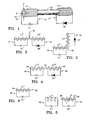
- Figure 1 is a diagram of a preferred embodiment of the frequency divider of the present invention.
- Figure 2 is a diagram of an alternative preferred embodiment of the frequency divider of the present invention.
- Figure 3 is a diagram of another alternative preferred embodiment of the frequency divider of the present invention.
- Figure 4 is a diagram of still another alternative preferred embodiment of the frequency divider of the present invention.
- Figure 5 is a diagram of yet another alternative preferred embodiment of the frequency divider of the present invention.
- Figure 6 is a diagram of a further alternative preferred embodiment of the frequency divider of the present invention.
- Figure 7 is a diagram of another preferred embodiment of the frequency divider of the present invention.
- Figure 7A is a schematic circuit diagram of the frequency divider of Figure 1.
- Figure 8 is a diagram of an alternative preferred embodiment of the frequency divider of the present invention.
- Figure 9 is a diagram of a presence detection system according to the present invention, including a tag according to the present invention.
- Referring to Figure 1, a preferred embodiment of a frequency divider according to the present invention includes a first
resonant circuit 10 consisting of a capacitor C1 connected in parallel with an inductance coil L1 wound about astraight ferrite rod 12; and a secondresonant circuit 14 consisting of a variable capacitance diode or varactor D2 connected in parallel with a second inductance coil L2 that is also wound about theferrite rod 12. - The first
resonant circuit 10 is resonant at a first frequency f1 for receiving electromagnetic radiation at the first frequency fi; and the secondresonant circuit 14 is resonant at a second frequency f2 that is one-half the first frequency f1 for transmitting electromagnetic radiation at the second frequency f2. Thefirst circuit 10 is coupled only magnetically by theferrite rod 12 and air to thesecond circuit 14 to transfer energy to thesecond circuit 14 at the first frequency f1 in response to receipt by thefirst circuit 10 of electromagnetic radiation at the first frequency f1. The variable capacitance diode or varactor D2 in thesecond circuit 14 is a variable reactance element in which the reactance varies with variations in energy transferred from thefirst circuit 10 for causing thesecond circuit 14 to transmit electromagnetic radiation at the second frequency f2 in response to the energy transferred from thefirst circuit 10 at the first frequency f, . - It is believed that the coil L1 of the first
resonant circuit 10 enhances the electromagnetic radiation at the first frequency f1 that is induced in the coil L2 of the secondresonant circuit 14, and thereby decreases the required field strength of electromagnetic radiation at the first frequency f1 necessary for accomplishing frequency division. - Because the values of the inductances in each of the
resonant circuits ferrite rod 12 in relation to each other and in relation to the ends of therod 12, theresonant circuits rod 12. - In order that the coils L1 and L2 are not so highly coupled to each other that adjusting the position of a coil in one resonant circuit so greatly affects the resonant frequency of the other resonant circuit as a result of the interactive coupling between the two coils as to make tuning of both resonant circuits difficult, the coils L1, L2 are wound with an inside dimension d' that is somewhat larger than the the cross-sectional dimension d" of the
ferrite rod 12. The coils L1, L2 are wound on a non-magnetic spacing element 16 that is adjustably mounted on theferrite rod 12. In the preferred embodiment, therod 12 has a diameter d" of approximately 0.125 inch (0.31 cm.); and the coils L1, L2 each have an inside diameter of approximately 0.15 inch (0.38 cm.). - It has been determined that in order to accomplish frequency division, the coupling coefficient "k" between the inductance coil L1 of the first
resonant circuit 10 and the inductance coil L2 of the secondresonant circuit 14 should be within a range of zero to 0.6; and that conversion of the energy of electromagnetic radiation at the first resonant frequency f1 received by the firstresonant circuit 10 into electromagnetic radiation radiated by the secondresonant circuit 14 at the second frequency f2 is most efficient when the coupling coefficient k is about 0.3. - In one example of the preferred embodiment of Figure 1, the coils L1 and L2 are wound on opposite ends of a 1.25 inch (3.2 cm.) long
straight ferrite rod 12 having a diameter of 0.125 inch (0.3 cm.). Each coil L1, L2 is approximately 0.375 inch (0.95 cm.) long, with the ends of the coils L1, L2 adjacent the respective ends of therod 12 being positioned ±0.125 inch from the ends of therod 12. The coils should be at least 0.375 inch apart to prevent such interactive coupling as would make tuning of bothresonant circuits rod 12. - The frequency divider of this example is activated at signal levels that are several orders of magnitude below those of prior art frequency dividers of similar size. Even more important the frequency division efficiency of this frequency divider as determined by its energy transfer function is very high, thereby enabling transmission of electromagnetic radiation at the frequency-divided second resonant frequency f2 having the same order of magnitude as provided by prior art frequency dividers that are many times larger.
- In this example, the capacitance C1 is a 680 pico-farad capacitor and the diode or varactor D1 has a varactor junction capacitance of approximately 600 pico-farads.
- A variable capacitance diode or varactor D1, which has one or a plurality of parallel varactor junctions that exhibit a large and nonlinear change in capacitance with small levels of applied alternating voltage, such as a zener diode, is utilized as the voltage-responsive-variable-reactance element in the second
resonant circuit 14 because of its low cost. In other embodiments some other device exhibiting the required large and nonlinear capacitance variation with applied alternating voltage, and having sufficiently low loss, and a high Q factor, could be substituted for a variable capacitance diode or varactor. - Low-magnetic-loss ferromagnetic materials other than ferrite can be utilized in the
rod 12 of the magnetic circuit means. - In an alternative embodiment (not shown), the magnetic circuit means used to couple the coils of the different resonant circuits is merely air. This embodiment is the least complex; and adequate magnetic coupling can be attained to provide a presence detection tag that is practical for some applications by disposing the coils in close proximity to one another. However, this embodiment may be more difficult to tune to the respective resonant frequencies in the absence of a ferrite core which enables fine adjustments of the resonant frequencies by adjustment of the positions of coils on the core, as discussed above.
- In various other preferred embodiments, the magnetic circuit means for coupling the coils of the different resonant circuits are ferrite elements having configurations other than that of a straight rod. By changing the shape of the magnetic circuit means, the orientation of the response of a tag containing the frequency divider may be tailored to specific applications and configurations of exciting electromagnetic fields at the first resonant frequency f1.
- In one such embodiment, as shown in Figure 2, the magnetic circuit means includes an L-
shaped ferrite element 20. In this embodiment, the frequency divider includes a firstresonant circuit 22 consisting of a capacitor C1' connected in parallel with an inductance coil L1' wound about one end of the L-shaped ferrite element 20; and a secondresonant circuit 24 consisting of a variable capacitance diode or varactor D2' connected in parallel with a second inductance coil L2' that is wound about the other end of the L-shaped ferrite element 20. In other respects the construction of the frequency divider of Figure 2 is subject to the conditions stated above with respect to the construction of the frequency divider of Figure 1, such that the operation of the frequency divider of Figure 2 is the same as the operation of the frequency divider of Figure 1. - In another such embodiment, as shown in Figure 3, more than two magnetic poles are incorporated into a
magnetic circuit element 30 for controlling the orientation and amount of coupling of the first resonant frequency f1 and the second resonant frequency f2 to the surrounding space. In this embodiment, the frequency divider includes a firstresonant circuit 32 consisting of a capacitor C1" connected in parallel with an inductance coil L 1" wound about one end of theferrite element 30; and a secondresonant circuit 34 consisting of a variable capacitance diode or varactor D2" connected in parallel with a second inductance coil L2" that is wound about the other end of theferrite element 30. In other respects the construction of the frequency divider of Figure 3 is subject to the conditions stated above with respect to the construction of the frequency divider of Figure 1, such that the operation of the frequency divider of Figure 3 is the same as the operation of the frequency divider of Figure 1. - The magnetic circuit means may include two or more separate ferrite rods that are closely magnetically coupled to each other to optimize performance and/or provide a magnetic circuit with a larger aperture than can be achieved with a single ferrite rod of the maximum manufacturable length. Currently ferrite rods cannot be cheaply manufactured with length-to-diameter ratios greater than ten or twelve. By disposing a plurality of straight ferrite rods end to end, the aperture of the magnetic circuit can be enlarged.
- Also by providing an air-gap in the magnetic circuit between separate ferrite rods upon which the coils of the separate resonant circuits are respectively disposed, the interactive magnetic coupling between the coils is decreased by decreasing the reluctance between the coils, thereby making the separate resonant circuits easier to tune by adjusting the positions of the coils on the rods.
- In one embodiment utilizing a plurality of ferromagnetic rods in the magnetic circuit, as shown in Figure 4, the magnetic circuit means include two straight
ferromagnetic rods air gap 44 therebetween. In this embodiment, the frequency divider includes a first resonant circuit 46 consisting of a capacitor C1 "' connected in parallel with an inductance coil L1 "' wound about one of theferrite rods 40; and a secondresonant circuit 48 consisting of a variable capacitance diode or varactor D2"' connected in parallel with a second inductance coil L2'" that is wound about the other of theferrite rods 42. In other respects the construction of the frequency divider of Figure 2 is subject to the conditions stated above with respect to the construction of the frequency divider of Figure 1, such that the operation of the frequency divider of Figure 4 is the same as the operation of the frequency divider of Figure 1. - In another embodiment of the present invention, as shown in Figure 5, the variable reactance element of the second resonant circuit is a variable inductance element rather than a variable capacitance element, as in the embodiment described above. In this embodiment, the frequency divider includes a first resonant circuit 50 consisting of a capacitor Cl* connected in parallel with an inductance coil Ll*; and a second
resonant circuit 52 consisting of a second capacitance C2* connected in parallel with a variable inductance element L2*. The first resonant circuit 50 and the secondresonant circuit 52 are coupled only magnetically by such magnetic circuit means as described above in relation to the description of the other embodiments. The variable inductance element L2* includes aninductance coil 56 and a low-lossferromagnetic material 58 that exhibits a large change in permeability within the desired voltage range of the incident electromagnetic radiation at the first predetermined frequency f1. The low-lossferromagnetic material 58 is placed in the magnetic circuit of theinductance coil 56. In this embodiment, not only are the bulk magnetic characteristics of theferromagnetic material 58 important, but also the physical shape of theferromagnetic material 58 has profound effects upon the frequency division characteristics of the secondresonant circuit 52. Ferrite materials are preferred for theferromagnetic material 58. The material formulation is selected to give the desired characteristics at the chosen operating frequency. With the proper design ofresonant circuits 50, 52, operation is possible from the low kilohertz region through the microwave region. In other respects the construction of the frequency divider of Figure 5 is subject to the conditions stated above with respect to the construction of the frequency divider of Figure 1, such that the operation of the frequency divider of Figure 5 is the same as the operation of the frequency divider of Figure 1. - In the embodiments of the frequency divider of the present invention described above, the resonant circuits have been described as including inductance coils and capacitances because the described embodiments are designed for use at relatively low frequencies. In embodiments of the frequency divider designed for use at high frequencies, such as those in the microwave region, the resonant circuits include elements embodying micro-strip, strip-line. and/or cavity technology.
- Also, in further embodiments of the frequency divider of the present invention, the second resonant circuit may be a device that mechanically resonates at the second frequency. A mechanically resonant device is equivalent to a parallel LC resonant circuit.
- In one such embodiment, as shown in Figure 6, the frequency divider includes a first resonant circuit 60 consisting of a capacitor C1" connected in parallel with an inductance coil L1"; and a second
resonant circuit 62 consisting ofstrip 64 of saturable magnetostrictive magnetic material that is mag- netomechanically resonant at a frequency f2 that is one-half the resonant frequency f1 of the first resonant circuit 60. The coil L1" of the first resonant circuit 60 is magnetically coupled to the mag- netomechanicallyresonant strip 64 by being wound around thestrip 64. The inside dimension of the coil L1" is spaced from thestrip 64 so as not to be so tightly wound around thestrip 64 as to make tuning of the first resonant circuit 60 difficult. - The
strip 64 is mechanically resonant in the length extensional mode and functions as a variable reactance core of field level variable permeability material to convert electromagnetic radiation received by the first resonant circuit 60 at the frequency f1 into electromagnetic radiation at the frequency f2 that is one-half the resonant frequency f1 of the first resonant circuit 60. - In the preferred embodiment the
strip 64 is a saturable magnetostrictive amorphous ferromagnetic material such as described in U.S. Patent No. 4,727,360 to Lucian G. Ferguson and Lincoln H. Charlot, Jr. - In other respects the construction of the frequency divider of Figure 6 is subject to the conditions stated above with respect to the construction of the frequency divider of Figure 1, such that the operation of the frequency divider of Figure 2 is the same as the operation of the frequency divider of Figure 1.
- Referring to Figure 7, a preferred embodiment of a frequency divider according to the present invention includes a first
resonant circuit 70 consisting of a variable capacitance diode or varactor D1 connected in parallel with an inductance coil L1 wound about astraight ferrite rod 72; and a secondresonant circuit 74 consisting of a variable capacitance diode or varactor D2 connected in parallel with a second inductance coil L2 that is also wound about theferrite rod 72. - The first
resonant circuit 70 is resonant at a first frequency f1 for receiving electromagnetic radiation at the first frequency fi; and the secondresonant circuit 74 is resonant at a second frequency f2 that is one-half the first frequency f1 for transmitting electromagnetic radiation at the second frequency f2. Thefirst circuit 70 is coupled only magnetically by theferrite rod 72 and air to thesecond circuit 74 to transfer energy to thesecond circuit 74 in response to receipt by thefirst circuit 70 of electromagnetic radiation at the first frequency f1. The variable capacitance diode or varactor D1 in thefirst circuit 70 is a variable reactance element in which the reactance varies with variations in energy received by thefirst circuit 70 for causing thesecond circuit 74 to vary in reactance mutual reactive coupling thereby causing the second circuit to transmit electromagnetic radiation at the second frequency f2 in response to the energy transferred from thefirst circuit 70 at the first frequency f1. The variable capacitance diode or varactor D2 in thesecond circuit 74 is a variable reactance element in which the reactance varies with variations in energy transferred from thefirst circuit 70 for causing thesecond circuit 74 to transmit electromagnetic radiation at the second frequency f2 in response to the energy transferred from thefirst circuit 70 and also aided by the mutual reactive coupling of the first circuit at the first frequency f, . - As best shown in Figure 7A, the sense of the windings of the coils L1 , L2 of the first and second
resonant circuits resonant circuit 70 is connected to the anode of the variable capacitance diode D1 , and the start of the winding of the coil L2 of the secondresonant circuit 74 is connected to the cathode of the variable capacitance diode D2 . This manner of connection achieves a power limiting action by reducing overloading effects at high input field levels as the variable capacitance diodes D1 , D2 tend to conduct in the forward diode region of their conductivity and thereby shunt some current across the respective coils L1 and L2 . - It is believed that the coil L1 of the first
resonant circuit 70 enhances the electromagnetic radiation at the first frequency f1 that is induced in the coil L2 of the secondresonant circuit 74, and thereby decreases the required field strength of electromagnetic radiation at the first frequency f1 necessary for accomplishing frequency division and also aides the varying of the reactance of the second resonant circuit by mutual coupling due to the varying reactance of the first resonant circuit. - Because the values of the inductances in each of the
resonant circuits ferrite rod 72 in relation to each other and in relation to the ends of therod 72, theresonant circuits rod 72. - In order that the coils L1 and L2 are not so highly coupled to each other that adjusting the position of a coil in one resonant circuit so greatly affects the resonant frequency of the other resonant circuit as a result of the interactive coupling between the two coils as to make tuning of both resonant circuits difficult, the coils L1 , L2 are wound with an inside dimension d' that is somewhat larger than the the cross-sectional dimension d" of the
ferrite rod 72. The coils L1 , L2 are wound on anon-magnetic spacing element 76 that is adjustably mounted on theferrite rod 72. - It has been determined that in order to accomplish frequency division, the coupling coefficient "k" between the inductance coil L1 of the first
resonant circuit 70 and the inductance coil L2 of the secondresonant circuit 74 should be within a range of zero to 0.6; and that conversion of the energy of electromagnetic radiation at the first resonant frequency f1 received by the firstresonant circuit 70 into electromagnetic radiation radiated by the secondresonant circuit 74 at the second frequency f2 is most efficient when the coupling coefficient k is about 0.3. - In one example of the preferred embodiment of Figure 7, the coils L1 and L2 are wound on opposite ends of a 1.25 inch (3.2 cm.) long
straight ferrite rod 72 having a diameter of 0.125 inch (0.3 cm.). Each coil L1 , L2 is approximately 0.375 inch (0.95 cm.) long, with the ends of the coils L1 , L2 adjacent the respective ends of therod 72 being positioned ±0.125 inch from the ends of therod 72. The coils should be at least 0.375 inch apart to prevent such interactive coupling as would make tuning of bothresonant circuits rod 72. - The frequency divider of this example is activated at signal levels that are several orders of magnitude below those of prior art frequency dividers of similar size. Even more important the frequency division efficiency of this frequency divider as determined by its energy transfer function is very high, thereby enabling transmission of electromagnetic radiation at the frequency-divided second resonant frequency f2 having the same order of magnitude as provided by prior art frequency dividers that are many times larger.
- In this example, the variable capacitance diode or varactor D1 has a varactor junction capacitance of approximately 600 pico-farads and the variable capacitance diode or varactor D2 has a varactor junction capacitance of approximately 800 pico-farads.
- In an integrated circuit embodiment, both of the variable capacitance diodes or varactors D1 , D2 are formed with a common cathode. In this embodiment frequency division occurs over a wider range because of limiting action of the variable capacitance diodes or varactors D1 , D2 .
- Variable capacitance diodes or varactors D1 , D2 which have one or a plurality of parallel varactor junctions that exhibit a large and nonlinear change in capacitance with small levels of applied alternating voltage, such as zener diodes, are utilized as the voltage-responsive-variable-reactance elements in the first and second
resonant circuits - Low-magnetic-loss ferromagnetic materials other than ferrite can be utilized in the
rod 72 of the magnetic circuit means. - In an alternative embodiment (not shown), the magnetic circuit means used to couple the coils of the different resonant circuits is merely air. This embodiment is the least complex; and adequate magnetic coupling can be attained to provide a presence detection tag that is practical for some applications by disposing the coils in close proximity to one another. However, this embodiment may be more difficult to tune to the respective resonant frequencies in the absence of a ferrite core with enables fine adjustments of the resonant frequencies by adjustment of the positions of coils on the core, as discussed above.
- In various other preferred embodiments (not shown), the magnetic circuit means for coupling the coils of the different resonant circuits are ferrite elements having configurations other than that of a straight rod. By changing the shape of the magnetic circuit means, the orientation of the response of a tag containing the frequency divider may be tailored to specific applications and configurations of exciting electromagnetic fields at the first resonant frequency fi. In one such embodiment, the magnetic circuit means includes an L-shaped ferrite element, with the inductance coil of one resonant circuit being wound about one end of the L-shaped ferrite element; and the inductance coil of the other resonant circuit being wound about the other end of the L-shaped ferrite element. In other respects the construction of such a frequency divider is subject to the conditions stated above with respect to the construction of the frequency divider of Figure 7, so that the operation of such a frequency divider is the same as the operation of the frequency divider of Figure 7.
- In another such embodiment, more than two ferrite rods are incorporated into a magnetic circuit element for controlling the orientation and amount of coupling of the first resonant frequency f1 and the second resonant frequency f2 to the surrounding space. In other respects the construction of the frequency divider of such an embodiment is subject to the conditions stated above with respect to the construction of the frequency divider of Figure 7, such that the operation of the frequency divider of such an embodiment is the same as the operation of the frequency divider of Figure 7.
- The magnetic circuit means may include two or more separate ferrite rods that are closely magnetically coupled to each other to optimize performance and/or provide a magnetic circuit with a larger aperture than can be achieved with a single ferrite rod of the maximum manufacturable length. Currently ferrite rods cannot be cheaply manufactured with length-to-diameter ratios greater than ten or twelve. By disposing a plurality of straight ferrite rods end to end, the aperture of the magnetic circuit can be enlarged.
- Also by providing an air-gap in the magnetic circuit between separate ferrite rods upon which the coils of the separate resonant circuits are respectively disposed, the interactive magnetic coupling between the coils is decreased by decreasing the reluctance between the coils, thereby making the separate resonant circuits easier to tune by adjusting the positions of the coils on the rods.
- In one embodiment utilizing a plurality of ferromagnetic rods in the magnetic circuit, the magnetic circuit means include two straight ferromagnetic rods disposed end to end with an air gap therebetween. In this embodiment, the inductance coil of the first resonant circuit is wound about one of the ferrite rods, and the inductance coil of the second resonant circuit is wound about the other of the ferrite rods. In other respects the construction of the frequency divider of such an embodiment is subject to the conditions stated above with respect to the construction of the frequency divider of Figure 7, so that the operation of the frequency divider of such an embodiment is the same as the operation of the frequency divider of Figure 7.
- In another embodiment of the present invention, as shown in Figure 8, a frequency divider according to the present invention includes a first
resonant circuit 80 consisting of a variable capacitance diode or varactor D1 connected in parallel with an inductance coil L1 wound about astraight ferrite rod 82; and a secondresonant circuit 84 consisting of a capacitance C2 connected in parallel with a second inductance coil L2 that is also wound about theferrite rod 82. - The first
resonant circuit 80 is resonant at a first frequency f1 for receiving electromagnetic radiation at the first frequency fi; and the secondresonant circuit 84 is resonant at a second frequency f2 that is one-half the first frequency f1 for transmitting electromagnetic radiation at the second frequency f2. Thefirst circuit 80 is coupled only magnetically by theferrite rod 82 and air to thesecond circuit 84 to transfer energy to thesecond circuit 84 in response to receipt by thefirst circuit 80 of electromagnetic radiation at the first frequency f1. The variable capacitance diode or varactor D1 in thefirst circuit 80 is a variable reactance element in which the reactance varies with variations in energy received by thefirst circuit 80 for causing thesecond circuit 84 to vary in reactance by mutual coupling to transmit electromagnetic radiation at the second frequency f2 in response to the energy transferred from thefirst circuit 80 at the first frequency f, . - Although the embodiment of Figure 8 is very inefficient in relation to the embodiments discussed above, it does function as a frequency divider because some variable reactance is reflected into the second
resonant circuit 84 by reason of the magnetic coupling of the tworesonant circuits - In other respects the construction of the frequency divider of Figure 8 is subject to the conditions stated above with respect to the construction of the frequency divider of Figure 7, such that the operation of the frequency divider of Figure 8 is the same as the operation of the frequency divider of Figure 7.
- In other embodiments of the frequency divider of the present invention, the inductance coils of the first and/or resonant circuits may also be variable reactance elements. Such variable inductance elements are provided in addition to the variable capacitance diode or varactor in the first resonant circuit in the embodiment of Figure 7, or in addition to the variable capacitance diodes or varactors in the first and second resonant circuits in the embodiment of Figure 7. A variable inductance element is formed by winding a coil about a low-loss
ferromagnetic material 58 that exhibits a large change in permeability within the desired voltage range of the incident electromagnetic radiation at the resonant frequency of the respective resonant circuit. In these embodiments, not only are the bulk magnetic characteristics of the ferromagnetic material important but also the physical shape of the ferromagnetic material has profound effects upon the frequency division characteristics of the resonant circuits. Ferrite materials are preferred for the ferromagnetic material. The material formulation is selected to give the desired characteristics at the chosen operating frequency. With proper design, operation is possible from the low kilohertz region through the microwave region. - In the embodiments of the frequency divider of the present invention described above, the resonant circuits have been described as including inductance coils and capacitances because the described embodiments are designed for use at relatively low frequencies. In embodiments of the frequency divider designed for use at high frequencies, such as those in the microwave region, the resonant circuits include elements embodying micro-strip, strip-line, and/or cavity technology.
- The frequency divider of the present invention is utilized in a preferred embodiment of a presence detection system according to the present invention, as shown in Figure 9. Such system includes a
transmitter 90, atag 91 and adetection system 92. - The transmitter transmits an
electromagnetic radiation signal 94 of a first predetermined frequency into asurveillance zone 96. - The
tag 91 is attached to an article (not shown) to be detected within thesurveillance zone 96. Thetag 91 includes a batteryless, portable frequency divider in accordance with the present invention, such as the frequency divider described above with reference to Figure 1 or Figure 7. - The
detection system 92 detectselectromagnetic radiation 98 in the surveillance zone 68 at a second predetermined frequency that is one-half the first predetermined frequency, and thereby detects the presence of the tag in thesurveillance zone 96. - The presence detection system utilizing a tag including the frequency divider of the present invention is used for various applications that take advantage of the size and efficiency of such frequency divider, including applications utilizing longer range tags, and applications utilizing small tags requiring only a short communication range.
- In one example, small tags including the frequency divider of the present invention are subcutaneously implanted in animals and such animals are counted by the presence detection system.
- In another example, small tags including the frequency divider of the present invention are implanted in non-metallic canisters of explosives and such canisters are detected by the presence detection system.
- In still another example, tags including embodiments of the frequency divider of the present invention that are relatively large in one dimension are implanted in non-metallic gun stocks and the guns are detected by the presence detection system.
Claims (10)
wherein the second circuit (74) includes a variable reactance element (D2 ) in which the reactance varies with variations in energy transferred from the first circuit for causing the second circuit to transmit electromagnetic radiation at the second frequency in response to the energy transferred from the first circuit at the first frequency.
Applications Claiming Priority (4)
| Application Number | Priority Date | Filing Date | Title |
|---|---|---|---|
| US562475 | 1990-08-03 | ||
| US07/562,471 US5065138A (en) | 1990-08-03 | 1990-08-03 | Magnetically-coupled two-resonant-circuit, frequency divider for presence-detection-system tag |
| US07/562,475 US5065137A (en) | 1990-08-03 | 1990-08-03 | Magnetically-coupled, two-resonant-circuit, frequency-division tag |
| US562471 | 1990-08-03 |
Publications (3)
| Publication Number | Publication Date |
|---|---|
| EP0469769A2 true EP0469769A2 (en) | 1992-02-05 |
| EP0469769A3 EP0469769A3 (en) | 1992-12-30 |
| EP0469769B1 EP0469769B1 (en) | 1997-05-07 |
Family
ID=27072966
Family Applications (1)
| Application Number | Title | Priority Date | Filing Date |
|---|---|---|---|
| EP91306658A Expired - Lifetime EP0469769B1 (en) | 1990-08-03 | 1991-07-22 | Magnetically-coupled, two-resonant-circuit, frequency-division tag |
Country Status (8)
| Country | Link |
|---|---|
| EP (1) | EP0469769B1 (en) |
| JP (1) | JP3224564B2 (en) |
| AT (1) | ATE152848T1 (en) |
| AU (1) | AU635654B2 (en) |
| CA (1) | CA2047559C (en) |
| DE (1) | DE69125985T2 (en) |
| ES (1) | ES2100934T3 (en) |
| NO (1) | NO912997L (en) |
Cited By (4)
| Publication number | Priority date | Publication date | Assignee | Title |
|---|---|---|---|---|
| EP0561559A1 (en) * | 1992-03-18 | 1993-09-22 | Security Tag Systems, Inc. | Electrically-and-magnetically-coupled, batteryless, portable frequency divider |
| US5751213A (en) * | 1994-02-07 | 1998-05-12 | Angstrom Sbrink; Leif | Theft detection alarm element for avoiding false alarms |
| WO2000004519A1 (en) * | 1998-07-14 | 2000-01-27 | Clan Holdings Ltd | Security tag |
| CN112041902A (en) * | 2018-03-05 | 2020-12-04 | 先讯美资电子有限责任公司 | RFID-enabled deactivation system and method for AM ferrite-based markers |
Families Citing this family (1)
| Publication number | Priority date | Publication date | Assignee | Title |
|---|---|---|---|---|
| US7199717B2 (en) * | 2004-02-17 | 2007-04-03 | Sensormatic Electronics Corporation | Frequency-division marker for an electronic article surveillance system |
Citations (2)
| Publication number | Priority date | Publication date | Assignee | Title |
|---|---|---|---|---|
| US4303910A (en) * | 1977-04-28 | 1981-12-01 | Parmeko Limited | Detection system |
| US4572976A (en) * | 1982-12-10 | 1986-02-25 | N.V. Nederlandsche Apparatenfabriek Nedap | Transponder for electromagnetic detection system with non-linear circuit |
Family Cites Families (3)
| Publication number | Priority date | Publication date | Assignee | Title |
|---|---|---|---|---|
| US4481428A (en) * | 1981-05-19 | 1984-11-06 | Security Tag Systems, Inc. | Batteryless, portable, frequency divider useful as a transponder of electromagnetic radiation |
| US4727360A (en) * | 1985-09-13 | 1988-02-23 | Security Tag Systems, Inc. | Frequency-dividing transponder and use thereof in a presence detection system |
| US4670740A (en) * | 1985-11-04 | 1987-06-02 | Security Tag Systems, Inc. | Portable, batteryless, frequency divider consisting of inductor and diode |
-
1991
- 1991-07-22 ES ES91306658T patent/ES2100934T3/en not_active Expired - Lifetime
- 1991-07-22 CA CA002047559A patent/CA2047559C/en not_active Expired - Fee Related
- 1991-07-22 EP EP91306658A patent/EP0469769B1/en not_active Expired - Lifetime
- 1991-07-22 DE DE69125985T patent/DE69125985T2/en not_active Expired - Fee Related
- 1991-07-22 AT AT91306658T patent/ATE152848T1/en not_active IP Right Cessation
- 1991-07-25 AU AU81325/91A patent/AU635654B2/en not_active Ceased
- 1991-08-01 NO NO91912997A patent/NO912997L/en unknown
- 1991-08-02 JP JP19434291A patent/JP3224564B2/en not_active Expired - Fee Related
Patent Citations (2)
| Publication number | Priority date | Publication date | Assignee | Title |
|---|---|---|---|---|
| US4303910A (en) * | 1977-04-28 | 1981-12-01 | Parmeko Limited | Detection system |
| US4572976A (en) * | 1982-12-10 | 1986-02-25 | N.V. Nederlandsche Apparatenfabriek Nedap | Transponder for electromagnetic detection system with non-linear circuit |
Cited By (4)
| Publication number | Priority date | Publication date | Assignee | Title |
|---|---|---|---|---|
| EP0561559A1 (en) * | 1992-03-18 | 1993-09-22 | Security Tag Systems, Inc. | Electrically-and-magnetically-coupled, batteryless, portable frequency divider |
| US5751213A (en) * | 1994-02-07 | 1998-05-12 | Angstrom Sbrink; Leif | Theft detection alarm element for avoiding false alarms |
| WO2000004519A1 (en) * | 1998-07-14 | 2000-01-27 | Clan Holdings Ltd | Security tag |
| CN112041902A (en) * | 2018-03-05 | 2020-12-04 | 先讯美资电子有限责任公司 | RFID-enabled deactivation system and method for AM ferrite-based markers |
Also Published As
| Publication number | Publication date |
|---|---|
| CA2047559A1 (en) | 1992-02-04 |
| DE69125985T2 (en) | 1997-12-11 |
| JPH04233696A (en) | 1992-08-21 |
| ES2100934T3 (en) | 1997-07-01 |
| CA2047559C (en) | 1999-07-06 |
| EP0469769A3 (en) | 1992-12-30 |
| ATE152848T1 (en) | 1997-05-15 |
| NO912997L (en) | 1992-02-04 |
| NO912997D0 (en) | 1991-08-01 |
| JP3224564B2 (en) | 2001-10-29 |
| AU635654B2 (en) | 1993-03-25 |
| DE69125985D1 (en) | 1997-06-12 |
| EP0469769B1 (en) | 1997-05-07 |
| AU8132591A (en) | 1992-02-06 |
Similar Documents
| Publication | Publication Date | Title |
|---|---|---|
| US5065137A (en) | Magnetically-coupled, two-resonant-circuit, frequency-division tag | |
| US5065138A (en) | Magnetically-coupled two-resonant-circuit, frequency divider for presence-detection-system tag | |
| US5241298A (en) | Electrically-and-magnetically-coupled, batteryless, portable, frequency divider | |
| US9406435B2 (en) | Misalignment insensitive wireless power transfer | |
| CN101828300A (en) | Transmitters and receivers for wireless energy transfer | |
| CA1223346A (en) | Antenna | |
| US20070296548A1 (en) | Resonant circuit tuning system using magnetic field coupled reactive elements | |
| GB2250893A (en) | Passive transponder system | |
| JP3866326B2 (en) | Signal powered frequency division transponder | |
| AU2002215265B2 (en) | An antenna device | |
| EP0469769B1 (en) | Magnetically-coupled, two-resonant-circuit, frequency-division tag | |
| AU2002215265A1 (en) | An antenna device | |
| US4929881A (en) | Probe for nuclear magnetic resonance apparatus | |
| KR20020062318A (en) | Cutoff transmission and/or reception antenna | |
| US20030076096A1 (en) | Apparatus and method of increasing the sensitivity of magnetic sensors used in magnetic field transmission and detection systems | |
| Zhuang et al. | Design and analysis of wireless power transfer systems insensitive to distance and position variation | |
| JPH03265305A (en) | Dual tuning antenna and signal generator having the antenna |
Legal Events
| Date | Code | Title | Description |
|---|---|---|---|
| PUAI | Public reference made under article 153(3) epc to a published international application that has entered the european phase |
Free format text: ORIGINAL CODE: 0009012 |
|
| AK | Designated contracting states |
Kind code of ref document: A2 Designated state(s): AT BE CH DE DK ES FR GB GR IT LI LU NL SE |
|
| PUAL | Search report despatched |
Free format text: ORIGINAL CODE: 0009013 |
|
| AK | Designated contracting states |
Kind code of ref document: A3 Designated state(s): AT BE CH DE DK ES FR GB GR IT LI LU NL SE |
|
| 17P | Request for examination filed |
Effective date: 19930213 |
|
| 17Q | First examination report despatched |
Effective date: 19940513 |
|
| GRAG | Despatch of communication of intention to grant |
Free format text: ORIGINAL CODE: EPIDOS AGRA |
|
| GRAH | Despatch of communication of intention to grant a patent |
Free format text: ORIGINAL CODE: EPIDOS IGRA |
|
| GRAH | Despatch of communication of intention to grant a patent |
Free format text: ORIGINAL CODE: EPIDOS IGRA |
|
| RAP1 | Party data changed (applicant data changed or rights of an application transferred) |
Owner name: SENSORMATIC ELECTRONICS CORPORATION |
|
| GRAA | (expected) grant |
Free format text: ORIGINAL CODE: 0009210 |
|
| AK | Designated contracting states |
Kind code of ref document: B1 Designated state(s): AT BE CH DE DK ES FR GB GR IT LI LU NL SE |
|
| PG25 | Lapsed in a contracting state [announced via postgrant information from national office to epo] |
Ref country code: IT Free format text: LAPSE BECAUSE OF FAILURE TO SUBMIT A TRANSLATION OF THE DESCRIPTION OR TO PAY THE FEE WITHIN THE PRESCRIBED TIME-LIMIT;WARNING: LAPSES OF ITALIAN PATENTS WITH EFFECTIVE DATE BEFORE 2007 MAY HAVE OCCURRED AT ANY TIME BEFORE 2007. THE CORRECT EFFECTIVE DATE MAY BE DIFFERENT FROM THE ONE RECORDED. Effective date: 19970507 Ref country code: GR Free format text: LAPSE BECAUSE OF FAILURE TO SUBMIT A TRANSLATION OF THE DESCRIPTION OR TO PAY THE FEE WITHIN THE PRESCRIBED TIME-LIMIT Effective date: 19970507 Ref country code: NL Free format text: LAPSE BECAUSE OF FAILURE TO SUBMIT A TRANSLATION OF THE DESCRIPTION OR TO PAY THE FEE WITHIN THE PRESCRIBED TIME-LIMIT Effective date: 19970507 Ref country code: AT Effective date: 19970507 Ref country code: BE Effective date: 19970507 Ref country code: LI Effective date: 19970507 Ref country code: CH Effective date: 19970507 Ref country code: DK Effective date: 19970507 |
|
| REF | Corresponds to: |
Ref document number: 152848 Country of ref document: AT Date of ref document: 19970515 Kind code of ref document: T |
|
| REG | Reference to a national code |
Ref country code: CH Ref legal event code: EP |
|
| REF | Corresponds to: |
Ref document number: 69125985 Country of ref document: DE Date of ref document: 19970612 |
|
| ET | Fr: translation filed | ||
| REG | Reference to a national code |
Ref country code: ES Ref legal event code: FG2A Ref document number: 2100934 Country of ref document: ES Kind code of ref document: T3 |
|
| PG25 | Lapsed in a contracting state [announced via postgrant information from national office to epo] |
Ref country code: LU Free format text: LAPSE BECAUSE OF NON-PAYMENT OF DUE FEES Effective date: 19970722 |
|
| NLV1 | Nl: lapsed or annulled due to failure to fulfill the requirements of art. 29p and 29m of the patents act | ||
| REG | Reference to a national code |
Ref country code: CH Ref legal event code: PL |
|
| PLBE | No opposition filed within time limit |
Free format text: ORIGINAL CODE: 0009261 |
|
| STAA | Information on the status of an ep patent application or granted ep patent |
Free format text: STATUS: NO OPPOSITION FILED WITHIN TIME LIMIT |
|
| 26N | No opposition filed | ||
| REG | Reference to a national code |
Ref country code: GB Ref legal event code: IF02 |
|
| REG | Reference to a national code |
Ref country code: FR Ref legal event code: CJ Ref country code: FR Ref legal event code: CD Ref country code: FR Ref legal event code: TP |
|
| REG | Reference to a national code |
Ref country code: ES Ref legal event code: PC2A |
|
| PGFP | Annual fee paid to national office [announced via postgrant information from national office to epo] |
Ref country code: ES Payment date: 20070726 Year of fee payment: 17 |
|
| PGFP | Annual fee paid to national office [announced via postgrant information from national office to epo] |
Ref country code: DE Payment date: 20070831 Year of fee payment: 17 |
|
| PGFP | Annual fee paid to national office [announced via postgrant information from national office to epo] |
Ref country code: GB Payment date: 20070727 Year of fee payment: 17 |
|
| PGFP | Annual fee paid to national office [announced via postgrant information from national office to epo] |
Ref country code: SE Payment date: 20070727 Year of fee payment: 17 |
|
| PGFP | Annual fee paid to national office [announced via postgrant information from national office to epo] |
Ref country code: FR Payment date: 20070717 Year of fee payment: 17 |
|
| EUG | Se: european patent has lapsed | ||
| GBPC | Gb: european patent ceased through non-payment of renewal fee |
Effective date: 20080722 |
|
| PG25 | Lapsed in a contracting state [announced via postgrant information from national office to epo] |
Ref country code: DE Free format text: LAPSE BECAUSE OF NON-PAYMENT OF DUE FEES Effective date: 20090203 |
|
| REG | Reference to a national code |
Ref country code: FR Ref legal event code: ST Effective date: 20090331 |
|
| PG25 | Lapsed in a contracting state [announced via postgrant information from national office to epo] |
Ref country code: GB Free format text: LAPSE BECAUSE OF NON-PAYMENT OF DUE FEES Effective date: 20080722 |
|
| PG25 | Lapsed in a contracting state [announced via postgrant information from national office to epo] |
Ref country code: FR Free format text: LAPSE BECAUSE OF NON-PAYMENT OF DUE FEES Effective date: 20080731 |
|
| REG | Reference to a national code |
Ref country code: ES Ref legal event code: FD2A Effective date: 20080723 |
|
| PG25 | Lapsed in a contracting state [announced via postgrant information from national office to epo] |
Ref country code: ES Free format text: LAPSE BECAUSE OF NON-PAYMENT OF DUE FEES Effective date: 20080723 |
|
| PG25 | Lapsed in a contracting state [announced via postgrant information from national office to epo] |
Ref country code: SE Free format text: LAPSE BECAUSE OF NON-PAYMENT OF DUE FEES Effective date: 20080723 |