EP0467656B1 - Method of operating an on-demand ink jet print head - Google Patents
Method of operating an on-demand ink jet print head Download PDFInfo
- Publication number
- EP0467656B1 EP0467656B1 EP91306471A EP91306471A EP0467656B1 EP 0467656 B1 EP0467656 B1 EP 0467656B1 EP 91306471 A EP91306471 A EP 91306471A EP 91306471 A EP91306471 A EP 91306471A EP 0467656 B1 EP0467656 B1 EP 0467656B1
- Authority
- EP
- European Patent Office
- Prior art keywords
- ink
- print head
- ink jet
- jet print
- drop
- Prior art date
- Legal status (The legal status is an assumption and is not a legal conclusion. Google has not performed a legal analysis and makes no representation as to the accuracy of the status listed.)
- Expired - Lifetime
Links
Images


Classifications
-
- B—PERFORMING OPERATIONS; TRANSPORTING
- B41—PRINTING; LINING MACHINES; TYPEWRITERS; STAMPS
- B41J—TYPEWRITERS; SELECTIVE PRINTING MECHANISMS, i.e. MECHANISMS PRINTING OTHERWISE THAN FROM A FORME; CORRECTION OF TYPOGRAPHICAL ERRORS
- B41J2/00—Typewriters or selective printing mechanisms characterised by the printing or marking process for which they are designed
- B41J2/005—Typewriters or selective printing mechanisms characterised by the printing or marking process for which they are designed characterised by bringing liquid or particles selectively into contact with a printing material
- B41J2/01—Ink jet
- B41J2/015—Ink jet characterised by the jet generation process
- B41J2/04—Ink jet characterised by the jet generation process generating single droplets or particles on demand
- B41J2/045—Ink jet characterised by the jet generation process generating single droplets or particles on demand by pressure, e.g. electromechanical transducers
- B41J2/04501—Control methods or devices therefor, e.g. driver circuits, control circuits
- B41J2/04516—Control methods or devices therefor, e.g. driver circuits, control circuits preventing formation of satellite drops
-
- B—PERFORMING OPERATIONS; TRANSPORTING
- B41—PRINTING; LINING MACHINES; TYPEWRITERS; STAMPS
- B41J—TYPEWRITERS; SELECTIVE PRINTING MECHANISMS, i.e. MECHANISMS PRINTING OTHERWISE THAN FROM A FORME; CORRECTION OF TYPOGRAPHICAL ERRORS
- B41J2/00—Typewriters or selective printing mechanisms characterised by the printing or marking process for which they are designed
- B41J2/005—Typewriters or selective printing mechanisms characterised by the printing or marking process for which they are designed characterised by bringing liquid or particles selectively into contact with a printing material
- B41J2/01—Ink jet
- B41J2/015—Ink jet characterised by the jet generation process
- B41J2/04—Ink jet characterised by the jet generation process generating single droplets or particles on demand
- B41J2/045—Ink jet characterised by the jet generation process generating single droplets or particles on demand by pressure, e.g. electromechanical transducers
- B41J2/04501—Control methods or devices therefor, e.g. driver circuits, control circuits
- B41J2/04581—Control methods or devices therefor, e.g. driver circuits, control circuits controlling heads based on piezoelectric elements
-
- B—PERFORMING OPERATIONS; TRANSPORTING
- B41—PRINTING; LINING MACHINES; TYPEWRITERS; STAMPS
- B41J—TYPEWRITERS; SELECTIVE PRINTING MECHANISMS, i.e. MECHANISMS PRINTING OTHERWISE THAN FROM A FORME; CORRECTION OF TYPOGRAPHICAL ERRORS
- B41J2/00—Typewriters or selective printing mechanisms characterised by the printing or marking process for which they are designed
- B41J2/005—Typewriters or selective printing mechanisms characterised by the printing or marking process for which they are designed characterised by bringing liquid or particles selectively into contact with a printing material
- B41J2/01—Ink jet
- B41J2/015—Ink jet characterised by the jet generation process
- B41J2/04—Ink jet characterised by the jet generation process generating single droplets or particles on demand
- B41J2/045—Ink jet characterised by the jet generation process generating single droplets or particles on demand by pressure, e.g. electromechanical transducers
- B41J2/04501—Control methods or devices therefor, e.g. driver circuits, control circuits
- B41J2/04588—Control methods or devices therefor, e.g. driver circuits, control circuits using a specific waveform
-
- B—PERFORMING OPERATIONS; TRANSPORTING
- B41—PRINTING; LINING MACHINES; TYPEWRITERS; STAMPS
- B41J—TYPEWRITERS; SELECTIVE PRINTING MECHANISMS, i.e. MECHANISMS PRINTING OTHERWISE THAN FROM A FORME; CORRECTION OF TYPOGRAPHICAL ERRORS
- B41J2/00—Typewriters or selective printing mechanisms characterised by the printing or marking process for which they are designed
- B41J2/005—Typewriters or selective printing mechanisms characterised by the printing or marking process for which they are designed characterised by bringing liquid or particles selectively into contact with a printing material
- B41J2/01—Ink jet
- B41J2/135—Nozzles
- B41J2/14—Structure thereof only for on-demand ink jet heads
- B41J2002/14387—Front shooter
-
- B—PERFORMING OPERATIONS; TRANSPORTING
- B41—PRINTING; LINING MACHINES; TYPEWRITERS; STAMPS
- B41J—TYPEWRITERS; SELECTIVE PRINTING MECHANISMS, i.e. MECHANISMS PRINTING OTHERWISE THAN FROM A FORME; CORRECTION OF TYPOGRAPHICAL ERRORS
- B41J2202/00—Embodiments of or processes related to ink-jet or thermal heads
- B41J2202/01—Embodiments of or processes related to ink-jet heads
- B41J2202/12—Embodiments of or processes related to ink-jet heads with ink circulating through the whole print head
Definitions
- the present invention relates to the operation of ink jet print heads and, in particular, to a method for generating a drive signal to control the operation of ink jet print heads.
- the present invention relates to printing with a drop-on-demand ("DOD") ink jet print head wherein ink drops are generated utilizing a drive signal that controls the operation of the ink jet print head to reduce rectified diffusion.
- Rectified diffusion is the growth of air bubbles dissolved in the ink from the repeated application of pressure pulses, at pressures below ambient pressure, to ink residing within the ink pressure chamber of the ink jet print head. Rectified diffusion results in print quality degradation over time.
- the drive signal may also simultaneously reduce rectified diffusion and enhance the consistency of drop flight time from the ink jet print head to print media over a wide range of drop ejection or drop repetition rates.
- Ink jet printers and in particular DOD ink jet printers having ink jet print heads with acoustic drivers for ink drop formation, are well known in the art.
- the principle behind an ink jet print head of this type is the generation of a pressure wave in and the resultant subsequent emission of ink droplets from an ink pressure chamber through a nozzle orifice or ink drop ejection orifice outlet.
- a wide variety of acoustic drivers is employed in ink jet print heads of this type.
- the drivers may consist of a pressure transducer formed by a piezoelectric ceramic material bonded to a thin diaphragm. In response to an applied voltage, the piezoelectric ceramic material deforms and causes the diaphragm to displace ink in the ink pressure chamber, which displacement results in a pressure wave and the flow of ink through one or more nozzles.
- Piezoelectric ceramic drivers may be of any suitable shape such as circular, polygonal, cylindrical, and annular-cylindrical. In addition, piezoelectric ceramic drivers may be operated in various modes of deflection, such as in the bending mode, shear mode, and longitudinal mode. Other types of acoustic drivers for generating pressure waves in ink include heater-bubble source drivers (so-called bubble or thermal ink jet print heads) and electromagnet-solenoid drivers. In general, it is desirable in an ink jet print head to employ a geometry that permits multiple nozzles to be positioned in a densely packed array, with each nozzle being driven by an associated acoustic driver.
- U.S. Patent No. 4,523,200 to Howkins describes one approach to operating an ink jet print head with the purpose of achieving high velocity ink drops free of satellites and orifice puddling and providing stabilized ink jet print head operation.
- an electromechanical transducer is coupled to an ink chamber and is driven by a composite signal including independent successive first and second electrical pulses of opposite polarity in one case and sometimes separated by a time delay.
- the first electrical pulse is an ejection pulse with a pulse width which is substantially greater than that of the second pulse.
- the illustrated second pulse in the case where the pulses are of opposite polarity has an exponentially decaying trailing edge.
- the application of the first pulse causes a rapid contraction of the ink chamber of the ink jet print head and initiates the ejection of an ink drop from the associated orifice.
- the application of the second pulse causes rapid expansion of the ink chamber and produces early break-off of an ink drop from the orifice.
- U.S. Patent No. 4,563,689 to Murakami et al. discloses an approach for operating an ink jet print head with the purpose of achieving different size drops on print media.
- a preceding pulse is applied to an electromechanical transducer prior to a main pulse.
- the preceding pulse is described as a voltage pulse that is applied to a piezoelectric transducer in order to oscillate ink in the nozzle.
- the energy contained in the voltage pulse is below the threshold necessary to eject a drop.
- the preceding pulse controls the position of the ink meniscus in the nozzle and thereby the ink drop size.
- the preceding and main pulses are of the same polarity, but in Figs. 9 and 11, these pulses are of opposite polarity.
- Murakami et al. also mentions that the typical delay time between the start of the preceding pulse to the start of the main pulse is on the order of 500 microseconds. Consequently, in this approach, drop ejection would be limited to relatively low repetition rates.
- the onset-period depends on the drop repetition rate, and, prior to the initiation of continuous ink jet print head operation, on the amount of air dissolved in the ink, the ink viscosity, the ink density, the diffusivity of air in the ink, and the radii of the air bubbles dissolved in the ink.
- a need also exists for a method that extends or eliminates the onset-period while simultaneously achieving high print quality at high printing rates.
- An object of the present invention is, therefore, to provide a method to control the operation of a DOD ink jet print head so that it may continue printing for an indefinite or extended period of time with little or no print quality degradation resulting from rectified diffusion.
- Another object of the present invention is to provide such a method to control the operation of the DOD ink jet print head so that it may print for a wide range of drop repetition rates, including high drop repetition rates.
- a drop-on-demand ink jet is described of the type having an ink chamber coupled to a source of ink, and ink drop forming orifice with an outlet, and in which the ink drop orifice is coupled to the ink chamber.
- An acoustic driver is used to produce a pressure wave in the ink to cause the ink to pass outwardly through the ink drop orifice and the outlet.
- the driver is operated to expand and contract he ink chamber to eject a drop of ink from the ink drop ejecting orifice outlet with the volume of the ink chamber first being expanded to refill the chamber with ink from a source of ink.
- ink is also withdrawn within the orifice toward the ink chamber and away from the ink drop ejection orifice outlet.
- a wait period is then established during which time the ink chamber is returning back to its original volume and the ink in the orifice to advance within the orifice away from the ink chamber and toward the ink drop ejection orifice outlet.
- the driver is then operated to contract the volume of the ink chamber to eject a drop of ink.
- each of the waiting steps may comprise the step of waiting until the ink in the orifice advances to substantially the same position within the orifice to which the ink advances during the other waiting steps before the ink chamber is contracted to eject an ink drop.
- the waiting step may comprise the step of waiting until the ink advances to a position substantially at the ink drop ejection orifice outlet, but not beyond such orifice outlet, before contracting the volume of the ink chamber to eject a drop of ink.
- the contracting step may conveniently occur at a time when the ink is advancing toward that is, has a forward component of motion toward, the ink drop ejection orifice outlet.
- the driver may comprise a piezoelectric driver which is driven by a drive pulse including first and second pulse components separated by a wait period, the first and second pulse components being of an opposite polarity.
- These pulse components or electric drive pulses may be of a square wave or trapezoidal wave form.
- the dominant acoustic resonance frequency of the ink jet may be determined in a known manner.
- the most significant factor affecting the acoustic resonance frequency of the ink jet is the length of ink passage from the outlet of the ink chamber to the orifice outlet of the ink jet.
- the energy content of the complete electric drive pulse at various frequencies is also determined.
- the complete electric drive pulse in this case includes the refill pulse components, the drive pulse components, and wait periods utilized in ejecting a drop of ink.
- a standard spectrum analyzer may be used to determine the energy content of the drive pulse at various frequencies.
- the drive pulse is then adjusted, preferably by adjusting the duration of the wait period and the first or refill pulse component, such that a minimum energy content of the drive pulse exists at the dominant acoustic resonance frequency of the ink jet.
- the dominant acoustic resonance frequency corresponds to the standing wave resonance frequency through liquid ink in the offset channel of the ink jet.
- the drive pulse may be adjusted, if necessary, such that the minimum energy content on the drive pulse at a frequency which substantially corresponds to the dominant acoustic frequency of the ink jet is at least about 20 db below the maximum energy content of the drive pulse at frequencies other than the frequency which substantially corresponds to the dominant acoustic resonance frequency.
- the drive pulse may be adjusted, such that the maximum energy content of the drive pulse does not occur at a frequency which is sufficiently close (for example, less than 10 KHz) to any of the major resonance frequencies of the ink jet print head.
- major resonance frequencies include the meniscus resonance frequency, Helmholtz resonance frequency, piezoelectric drive resonance frequency and various acoustic resonance frequencies of the different channels and passageways forming the ink jet print head.
- the drive pulse may have refill and ejection pulse components of a trapezoidal shape in which the pulse components have a different rate of rise to their maximum amplitude than the rate of fall from the maximum amplitude.
- the first electric drive pulse or refill pulse component may have a rise time from about 1 to about 4 microseconds, be at a maximum amplitude for from about 2 to about 7 microseconds, and may have a fall time from about 1 to about 7 microseconds.
- the wait period may be greater than about 8 microseconds.
- the second electric drive or eject pulse component may be within the same range of rise time, time at a maximum amplitude and fall time as the first electric drive pulse, but of opposite polarity.
- the rise time of the first and second electric drive pulse component may more preferably be from about 1 to about 2 microseconds, the first and second electric drive pulse component may be at its maximum amplitude for from about 4 to about 5 microseconds, and the first and second electric drive pulse may have a fall time of from about 2 to about 4 microseconds, with the wait period being from about 15 to about 22 microseconds.
- the present invention is constituted by a method to control the operation of a DOD ink jet print head to reduce print quality degradation resulting from rectified diffusion.
- the invention modifies the method of operating an ink jet print head recited earlier.
- the method described earlier summarized is a method of operating a DOD ink jet print head ("ink jet print head") having an ink pressure chamber coupled to a source of ink and having an ink drop ejecting orifice (“orifice") with an ink drop ejection orifice outlet (“orifice outlet”).
- the orifice of the ink jet print head is coupled to the ink pressure chamber.
- An acoustic driver operates to expand and contract the volume of the ink pressure chamber to eject a drop of ink from the orifice outlet.
- the acoustic driver applies a pressure wave to the ink residing within the ink pressure chamber to cause the ink to pass outwardly through the orifice and through the orifice outlet.
- the acoustic driver may comprise a piezoelectric ceramic material driven by voltage signal pulses.
- the acoustic driver Upon application of a first voltage pulse, called the "refill pulse component", the acoustic driver operates to increase the volume of the ink pressure chamber through chamber expansion to refill the chamber with ink from the ink source.
- the refill pulse component Upon application of a first voltage pulse, called the "refill pulse component", the acoustic driver operates to increase the volume of the ink pressure chamber through chamber expansion to refill the chamber with ink from the ink source.
- ink is also drawn back within the orifice toward the ink pressure chamber and away from the orifice outlet.
- a wait period state is then established during which time the ink pressure chamber returns to its original volume and the ink in the orifice advances within the orifice away from the ink pressure chamber and toward the orifice outlet.
- the acoustic driver Upon application of a second voltage pulse of opposite relative polarity, called the "ejection pulse component", the acoustic driver then operates to reduce the volume of the ink pressure chamber through chamber contraction to eject a drop of ink.
- a sequence of ink pressure chamber expansion, a wait period, and ink pressure chamber contraction accomplishes the ejection of ink drops.
- the refill pulse component, followed by the wait period state and the ejection pulse component comprise the drive signal.
- the refill pulse component and the ejection pulse component may be of a square wave or trapezoidal wave form.
- a preferred embodiment of the drive signal of the foregoing method comprises a bipolar electrical signal with refill and ejection pulse components varying about a zero amplitude reference voltage maintained during the wait period state; however, skilled persons would appreciate that the reference voltage need not have zero voltage amplitude.
- the drive signal may comprise pulse components of opposite relative polarity varying about a positive or negative reference voltage amplitude maintained during the wait period state.
- the drive signal is as mentioned earlier tuned to the characteristics of the ink jet printer head to avoid the presence of high energy components at the dominant acoustic resonant frequency of the ink jet print head, which may be determined in a known manner.
- the most significant factor affecting the dominant resonant frequency of the ink jet print head is the resonant frequency of the ink meniscus.
- a significant factor affecting the dominant acoustic resonant frequency of the ink jet print head is the length of the passage from the outlet of the ink pressure chamber to the orifice outlet of the ink jet print head. This passage is called
- the drive signal is tuned to the characteristics of the ink jet print head, preferably by adjusting the time duration of the wait period state and the time duration of the first or refill pulse component, including the rise time and fall time of the refill pulse component.
- the rise time and fall time for the refill pulse component is the transition time from zero voltage to the voltage amplitude of the refill pulse component and from the voltage amplitude of the refill pulse component to zero voltage, respectively.
- a standard spectrum analyzer may be used to determine the energy content of the drive signal at various frequencies. After a tuning adjustment, a minimum energy content of the drive signal coincides with the dominant acoustic resonant frequency of the ink jet print head.
- the method of the present invention for operating an ink jet print head to reduce print quality degradation resulting from rectified diffusion is accomplished by modifying the pulse components of the drive signal so that the pressure applied to the ink residing within the ink pressure chamber of the ink jet print head, such pressure being below ambient pressure, is less than the threshold pressure magnitude that leads to rectified diffusion.
- One approach to accomplish this entails generating a drive signal to achieve high print quality and high printing rates in accordance with the previously set forth description of the first aspect of the invention. When this approach is followed, the pulse components of the drive signal are then modified to reduce print quality degradation resulting from rectified diffusion.
- any drive signal may be modified so that the pressure below ambient pressure applied to the ink residing within the ink jet print head is less than the threshold pressure magnitude that leads to rectified diffusion.
- the magnitude of the voltage of the refill pulse component is reduced by fifty per cent, and the magnitude of the voltage of the ejection pulse component is reduced in relation to the newly established magnitude of the voltage of the refill pulse component.
- the magnitude of the voltage of the refill pulse component is less than 1.3 and greater than 1.15 of the magnitude of the voltage of the ejection pulse component.
- the relative polarities of the refill pulse component and the ejection pulse component may be reversed, depending upon the polarity of the pressure transducer.
- the time durations of the refill pulse and the ejection pulse components are then increased.
- the rise time and fall time for each of the refill and ejection pulse components are extended.
- the rise time and the fall time for each pulse component are the transition times, respectively, from zero voltage to the voltage amplitude of the pulse component and from the voltage amplitude to zero voltage.
- the rise and fall times for each of the refill and ejection pulse components are doubled.
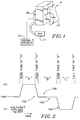
- a DOD ink jet print head 9 is illustrated with an internal ink pressure chamber (not shown in this figure) coupled to an ink source 11.
- the ink jet print head 9 has one or more ink drop ejection orifice outlets ("orifice outlets") 14, of which outlets 14a, 14b, and 14c are shown, coupled to or in communication with the ink pressure chamber by way of an ink drop ejecting orifice ("orifice").
- Ink passes through orifice outlets 14 during ink drop formation. Ink drops travel in a direction along a path from orifice outlets 14 toward a print medium 13, which is spaced from the orifice outlets.
- a typical ink jet printer includes a plurality of ink pressure chambers each coupled to one or more of the respective orifices and orifice outlets.
- An acoustic drive mechanism 36 is utilized for generating a pressure wave or pulse, which is applied to the ink residing within the ink pressure chamber to cause the ink to pass outwardly through the orifice and its associated orifice outlet 14.
- the acoustic driver 36 operates in response to signals from a signal source 37 to cause the pressure waves applied to the ink.
- the invention has particular applicability and benefits when piezoelectric ceramic drivers are used in ink drop formation.
- One preferred form of an ink jet print head using this type of acoustic driver is described in detail in US Patent Application No 07/430,213 (corresponding to European Patent Application No 90 311977.4).
- electromagnet-solenoid drivers as well as other shapes of piezoelectric ceramic drivers (eg, circular, polygonal, cylindrical, and annular-cylindrical) may be used.
- various modes of deflection of piezoelectric ceramic drivers may also be used, such as bending mode, shear mode, and longitudinal mode.
- one form of ink jet print head 9 in accordance with the disclosure of the patent application just referred to has a body 10 which defines an ink inlet 12 through which ink is delivered to the ink jet print head.
- the body 10 also defines an orifice outlet or nozzle 14 together with an ink flow path 28 from the ink inlet 12 to the nozzle 14.
- an ink jet print head of this type would preferably include an array of nozzles 14 which are proximately disposed, that is closely spaced from one another, for use in printing drops of ink onto a print medium.
- a typical colour ink jet print head has at least four such manifolds for receiving, respectively, black, cyan, magenta, and yellow ink for use in black plus three color subtraction printing.
- the number of such ink supply manifolds may be varied depending upon whether a printer is designed to print solely in black ink or with less than a full range of color.
- ink flows through an ink inlet channel 18, through an ink inlet 20 and into an ink pressure chamber 22.
- Ink leaves the ink pressure chamber 22 by way of an ink pressure chamber outlet 24 and flows through an ink passage 26 to the nozzle 14 from which ink drops are ejected.
- Arrows 28 diagram this ink flow path.
- the ink pressure chamber 22 is bounded on one side by a flexible diaphragm 34.
- the pressure transducer in this case a piezoelectric ceramic disc 36 secured to the diaphragm 34, as by epoxy, overlays the ink pressure chamber 22.
- the piezoelectric ceramic disc 36 has metal film layers 38 to which an electronic circuit driver, not shown in Fig. 3, but indicated at 37 in Fig. 1, is electrically connected.
- the illustrated transducer is operated in its bending mode. That is, when a voltage is applied across the piezoelectric ceramic disc, the disc attempts to change its dimensions. However, because it is securely and rigidly attached to the diaphragm 34, bending occurs.
- an optional ink outlet or purging channel 42 is also defined by the body 10 of ink jet print head 9.
- the purging channel 42 is coupled to the ink passage 26 at a location adjacent to, but interior to, the nozzle 14.
- the purging channel 42 communicates from ink passage 26 to an outlet or purging manifold 44 which is connected by a purging outlet passage 46 to a purging outlet port 48.
- the purging manifold 44 is typically connected by similar purging channels 42 to similar ink passages 26 associated with multiple nozzles 14.
- ink flows in a direction indicated by arrows 50, through purging channel 42, purging manifold 44, purging outlet passage 46 and to the purging outlet port 48.
- the body 10 is preferably formed of plural laminated plates or sheets, such as of stainless steel. These sheets are stacked in superposed relationship.
- these sheets or plates include a diaphragm plate 60, which forms the diaphragm and also defines the ink inlet 12 and purging outlet 48; and ink pressure chamber plate 62, which defines the ink pressure chamber 22, a portion of the ink supply manifold, and a portion of the purging passage 48; a separator plate 64, which defines a portion of the ink passage 26, bounds one side of the ink pressure chamber 22, defines the inlet 20 and outlet 24 to the ink pressure chamber, defines a portion of the ink supply manifold 16 and also defines a portion of the purging passage 46; an ink inlet plate 66, which defines a portion of the passage 26, the inlet channel 18, and a portion of the purging passage 46; another separator plate 68 which defines portions of the passages 26 and 46
- More or fewer plates than illustrated may be used to define the various ink flow passageways, manifolds and pressure chambers.
- multiple plates may be used to define an ink pressure chamber instead of a single plate as illustrated in FIG 3.
- not all the various features need be in separate sheets or layers of metal.
- Exemplary dimensions for elements of the ink jet print head of Fig. 3 are set forth in Table 1 below. TABLE 1 Representative Dimensions and Resonant Characteristics For Figure 3 Ink Jet Print Heads Feature Cross Section Length Frequency of Resonance Ink Supply Channel 18 008"x0.010" 0.268" 60-70KHz Diaphragm Plate 60 0.110"dia. 0.004" 160-180KHz Body Chamber 22 0.110"dia.
- the various layers forming the ink jet print head may be aligned and bonded in any suitable manner, including by the use of suitable mechanical fasteners.
- suitable mechanical fasteners include aluminum, copper, copper, and zinc.
- one approach for bonding the metal layers is described in US Patent No 4,883,219 to Anderson, et al, and entitled “Manufacture of Ink Jet Print Heads by Diffusion Bonding and Brazing.”
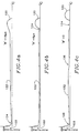
- Fig. 2 One form of drive signal for controlling the operation of ink jet print heads utilizing acoustic drivers to achieve high print quality and high printing rates is illustrated in Fig. 2.
- This particular drive signal is a bipolar electrical pulse 100 with a refill pulse component 102 and an ejection pulse component 104.
- the components 102 and 104 are voltages of opposite relative polarity of possibly different voltage amplitudes.
- These electrical pulses or pulse components 102, 104 are also separated by a wait period state indicated by 106.
- the time duration of the wait period 106 is indicated as "B" in Fig. 2.
- the relative polarities of the pulse components 102, 104 may be reversed from that shown in Fig. 2, depending upon the polarization of the piezoelectric ceramic driver mechanism 36 (Fig. 1).
- Fig. 1 One form of drive signal for controlling the operation of ink jet print heads utilizing acoustic drivers to achieve high print quality and high printing rates.
- FIG. 2 demonstrates the representative shape of the drive signal, but does not provide representative values for the various attributes of the signal or its pulse components, such as voltage amplitudes, time durations or rise times and fall times. Furthermore, although the pulse components of the drive signal shown in Fig. 2 have trapezoidal or square wave form, in actual operation these pulse components may exhibit exponentially rising leading edges and exponentially decaying trailing edges.
- a preferred embodiment of the drive signal comprises a bipolar electrical signal with refill and ejection pulse components varying about a zero voltage amplitude maintained during the wait period 106; however, the invention is not limited to this particular embodiment.
- the drive signal may comprise pulse components of opposite relative polarity varying about a positive or negative reference voltage amplitude maintained during the wait period state.
- the ink pressure chamber 22 expands upon the application of the refill pulse component 102 and draws ink into the ink pressure chamber 22 from the ink source 11 to refill the ink pressure chamber 22 following the ejection of a drop.
- the ink pressure chamber 22 begins to contract and moves the ink meniscus forward in the ink orifice 103 (Fig. 3) toward the orifice outlet 14.
- the ink meniscus continues toward the orifice outlet 14.
- the ejection pulse component 104 the ink pressure chamber 22 is rapidly constricted to cause the ejection of a drop of ink.
- the ink meniscus is once again drawn back into the ink orifice 103 away from the orifice outlet 14 as a result of the application of the refill pulse component 102.
- the time duration of the refill pulse component is less than the time required for the ink meniscus to return to a position adjacent to the orifice outlet 14 for ejection of a drop of ink.
- the time duration of the refill pulse component 102 is less than one-half of the time period associated with the resonant frequency of the ink meniscus. More preferably, this duration is less than about one-fifth of the time period associated with the resonant frequency of the ink meniscus.
- the resonant frequency of an ink meniscus in an orifice of an ink jet print head can be easily calculated from the properties of the ink, including the volume of the ink inside the ink jet print head, and the dimensions of the orifice in a known manner.
- the time duration of the wait period "B" increases, the ink meniscus moves closer to the orifice outlet 14 at the time the ejection pulse component 104 is applied.
- the time duration of the wait period 106 and of the ejection pulse component 104 is less than about one-half of the time period associated with the resonant frequency of the ink meniscus.
- typical time periods associated with the resonant frequency of the ink meniscus range from about 50 microseconds to about 160 microseconds, depending upon the configuration of the specific ink jet print head and the particular ink.
- the pulse components 102 and 104 of the drive signal controlling the operation of the ink jet print head to achieve high print quality and high printing rates are shown in Fig. 2 as being generally trapezoidal and of opposite polarity. Square wave pulse components may also be used. A conventional signal source 37 may be used to generate pulses of this shape. Other pulse shapes may also be used.
- a suitable refill pulse component 102 is one which results in increasing the volume of the ink pressure chamber 22 through the expansion of the chamber to refill the chamber with ink from the ink source 11 while withdrawing the ink in the ink orifice 103 back toward the ink pressure chamber 22 and away from the orifice outlet 14.
- the wait period 106 is a period during which essentially zero voltage is applied to the acoustic driver.
- the ejection pulse component 104 is of a shape which causes a rapid contraction of the ink pressure chamber 22 following the wait period 106 to reduce the volume of the chamber and eject a drop of ink.
- a drive signal composed of pulses of the form shown in Fig. 2 is repeatedly applied to cause the ejection of ink drops.
- One or more pulses may be applied to cause the formation of each drop, but, in a preferred embodiment, one such composite drive signal is used to form each of the drops.
- the time duration of the wait period 106 is typically set to allow the ink meniscus in the ink orifice 103 to advance to substantially the same position within the orifice during each wait period before contraction of the ink pressure chamber 22 to eject a drop. It is preferable that the ink meniscus have a remnant of forward velocity within ink orifice 103 toward orifice outlet 14 at the time of arrival of the pressure pulse in response to the ejection pulse component 104 of Fig. 2.
- the fluid column propelled out of the ink jet print head properly coalesces into a drop to thereby minimize the formation of satellite drops.
- the ink meniscus should not advance to a position beyond the orifice outlet 14. If ink is allowed to project beyond the orifice outlet 14 for a substantial period of time before the ejection pulse 104 is applied, it may wet the surface surrounding the orifice outlet. This wetting may cause an asymmetric deflection of ink drops and non-uniform drop formation as the various drops are formed and ejected. By positioning the ink meniscus at substantially the same position prior to the pressure pulse, uniformity of drop flight time to the print medium is enhanced over a wide range of drop ejection rates.
- the ink meniscus have a remnant of forward velocity within the orifice 103 toward outlet 14 at the time of arrival of the pressure pulse in response to the eject pulse component 104 of FIG 2.
- the eject pulse component 104 causes the diaphragm 34 of the pressure transducer to rapidly move inwardly toward the ink chamber 22 and results in a sudden pressure wave. This pressure wave ejects the drop of ink presented at the orifice outlet at the end of the wait period.
- diaphragm returns toward its original position and, in so doing, initiates a negative pressure wave which assists in breaking off an ink drop.
- Exemplary durations of the various pulse components for achieving high print quality and high printing rates are 5 microseconds for the "A" portion of the refill pulse component 102, with rise and fall times of respectively 1 microsecond and 3 microseconds; a wait period "B" of 15 microseconds; and an ejection pulse component 104 with a "C” portion of 5 microseconds and with rise and fall times like those of the refill pulse component 102.
- Fig. 2 demonstrates the representative shape of the drive signal, but does not provide representative values for its various attributes. To achieve high print quality and high print rates, it may sometimes be advantageous to reduce the duration of these time periods so that the fluidic system may be reinitialized as quickly as possible, thereby making faster printing rates possible.
- An alternative method to increase the drop repetition rate for the drive signal comprises reducing the time duration from the trailing edge of the ejection pulse component to the leading edge of the refill pulse component. This method has the advantage that it does not affect the time durations of the pulse components, including rise and fall times.
- Fig. 4 illustrates a simulation of the change in shape of an ejected ink column when an ink jet print head of the type illustrated in Fig. 3 is actuated by a drive signal composed of the exemplary durations above.
- Figs. 4a, 4b, and 4c demonstrate the effect of varying the wait period 106.
- the main volume of ink 120 forms a spherical head which is connected to a long tapering tail 122 with drop breakoff occurring at a location 124 between the tail of this filament and the orifice outlet 14.
- the tail 122 After drop breakoff the tail 122 starts to coalesce into the head 120 and does not form a spherical drop by the time it reaches the print medium. However, due to the relatively high speed of the ink column with respect to the print medium the resulting spot on the print medium is nearly spherical.
- the drop breakoff point 124 is adjacent to the main volume of ink 120 and results in a cleanly formed drop.
- the tail 122 of the drop breaks off subsequently to the orifice outlet 14 and forms a satellite drop which moves at a relatively smaller velocity than that of the main drop. Consequently, the main drop 120 and satellite drop 122 form two separate spots on the print medium.
- the drop breakoff point 124 occurs adjacent to the main drop volume 120.
- the remaining ink filament 122 has weak points, indicated at 126 and 128, corresponding to potential locations at which the filament may break off and form satellite drops.
- the Fig. 4 illustrations are the result of a theoretical model of the operation of the ink jet print head of Fig. 3 using the form of the drive signal shown in Fig. 2.
- the Fig. 4 illustrations show only the upper half of the formed drop above the center line of the ink orifice 103 in each of these figures.
- a pull back or refill pulse such as pulse component 102 alone, nor an eject pulse, such as component 104 alone, results in satisfactory print performance, even though drop ejection may be accomplished by either of the pulse components 104, 106 alone.
- using just a refill pulse component 104 would tend to severely limit the drop ejection speed, such as to about 3.5 meters per seconds or less.
- increasing the magnitude or duration of the refill pulse components 104 in an attempt to increase drop speed, would result in pulling the meniscus so far into the upstream edge of the ink orifice 103 that ingestion of air bubbles may result.
- High drop speeds are desirable, such as on the order of 6 meters per second or more, to increase the capacity of an ink jet printer to operate at high drop ejection rates.
- an eject pulse component 106 only results in a rhythmical variation in drop speed with changing drop ejection rates.
- the frequency of the rhythmical variations may be verified from the information in Table 1 to be the same as that of the reverberation resonance in the channel sections forming the ink flow path between the ink chamber 22 and the ink orifice outlet 14.
- an eject pulse component only drive signal may be designed which smooths the speed or flight time variations by using a drive pulse with a frequency spectrum which deliberately removes energy from the reverberations. However, in this case, the ink volume per drop declines as the ejection rate increases.
- the ink chamber does not adequately refill between drop ejections at all drop ejection rates.
- a further disadvantage is that, since the same amount of energy is imparted by the piezoelectric element to every drop ejected regardless of refilling, the smaller drops tend to travel at faster speeds. Thus, as shown in FIG 13, the drop speed generally increases (corresponding to a decrease in flight drop time) as the drop ejection rate increases, although the rhythmical drop speed variations prominent in FIG 12 are absent.
- the deficiencies of the eject only pulse component drive approach are overcome by actuating a refill pulse component 104 first to actively refill the ink chamber 22.
- the offset channel 71 in FIG 3 is also refilled if the ink jet print head is of a design having such a channel.
- the ink chamber may be passively refilled fully be enlarging the ink inlet 18, 20 from the ink supply reservoir (11 in FIG 1), without using an active refill pulse component 104.
- the pressure pulse set up in the ink chamber 22 would flow into the conduit leading to the orifice 26 and also into the ink inlet 18, 20 itself.
- the portion of the pressure wave travelling into the ink inlet would then represent energy unavailable for the ink drop formation.
- the use of an active refill pulse component permits a smaller inlet opening 20 which reduces this potential loss of energy available for drop formation and also isolates the body chamber 22 and passageway 26 from pressure pulse disturbances originating in the ink reservoir or manifold 16 if the jet is a member of an array. This isolation is progressively reduced as the inlet opening 20 is enlarged. A balance is thus struck among the size of the ink inlet 20, the strength of the refill pulse component 102 (FIG 2) and the strength of the eject pulse component 104. A strong refill pulse component 102 will pull ink through the inlet opening 20 into the pressure chamber 22.
- Too strong of a refill pulse component will cause the ingestion of a bubble through the orifice outlet.
- too strong of an eject pulse component 104 will eject more ink in a single drop than the refill pulse component may be able to draw through the ink inlet 20.
- One preferred interrelationship of these parameters is described in Table 1 and in the exemplary pulse component durations mentioned above.
- the inclusion of a refill pulse component 102 in the drive signal tends to draw ink back from the external surface surrounding the orifice outlet 14. This action minimizes the possibility of ink wetting the surface surrounding the outlet and distorting the travel or breakoff of ink drops at the orifice outlet.
- the preferred time duration of the wait period "B" is a combined function of the time for the retracted ink meniscus in ink orifice 103 to reach the orifice outlet 14 and the velocity of the ink at the instant of arrival of the pressure pulse initiated by the ejection pulse component 104. It is desired that the retracted ink meniscus reach the orifice outlet 14 with waning velocity just before the pressure pulse from the ejection pulse component 104 is applied.
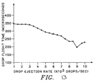
- Fig. 5 depicts the situation in which the ink jet print head is operated in the manner described to achieve high print quality and high printing rates.
- Fig. 5 is a plot of the drop flight time for an ink jet print head of the type shown in Fig. 3 versus drop ejection rate and is substantially constant over a range of drop ejection rates through and including ten thousand drops per second.
- the print medium was 1 mm from the ink jet print head orifice outlet 14, and drop speeds in excess of 6 meters per second were achieved.
- a maximum deviation of 30 microseconds was observed over an ink jet drop ejection rate ranging from 1,000 drops per second to 10,000 drops per second.
- the drop speeds are relatively fast with uniform drop sizes being available.
- the drop trajectories are substantially perpendicular to the orifice face plate for all drop ejection rates, inasmuch as the refill pulse component 102 of the drive signal assists in reducing wetting of the external surface surrounding the orifice outlet 14 which may cause a deflection of the ejected drops from a desired trajectory.
- satellite drop formation is minimized because this drive signal allows high viscosity ink, such as hot melt ink, within the conduit of the ink orifice 103 to behave as an intracavity acoustic absorber of pressure pulses reverberating in the offset channel 71 of an ink jet print head of the type shown in Fig. 3.
- the relatively simple drive signal of the type illustrated in Fig. 2 may be achieved with conventional off-the-shelf digital electronic drive signal sources.
- a preferred relationship between the drive pulse components 102, 104, and 106 has been experimentally determined for achieving high print quality and high printing rates. These preferred relationships, however, while achieving high print quality and high printing rates, ignore the potential effect on print quality degradation resulting from rectified diffusion.
- a wait period 106 of at least as great as and preferably greater than about 8 microseconds, uniform and consistent ink drop formation has been achieved. Shorter wait periods have been observed in some cases to increase the probability of formation of satellite drops.
- the time duration of the refill or expanding pulse component 102 is no more than about 16 to 20 microseconds.
- a greater refill pulse component time duration increases the possibility of ingesting bubbles into the orifice outlet 14.
- the refill pulse component time duration including rise time and fall time, need be no longer than necessary to replace the ink ejected during ink drop formation. Shorter refill pulse component time durations increase the drop repetition rate which may be achieved. However, as indicated, this ignores the effect that these shorter refill pulse component time durations may have upon print quality degradation resulting from rectified diffusion.
- the refill pulse component 102 has a time duration, including rise time and fall time, to achieve high print quality and high printing rates of no less than about 7 microseconds.
- the time duration of the ejection pulse component 104, including rise time and fall time, to achieve high print quality and high printing rates is typically no more than about 16 to 20 microseconds and no less than about 6 microseconds.
- ink jet print heads of the type shown in Fig. 3 have been operated at drop ejection rates through and including 10,000 drops per second, and higher, and at drop ejection speeds in excess of 6 meters per second.
- the drop speed nonuniformity has been observed at less than 15 percent over continuous and intermittent drop ejection conditions.
- the drop position error is much less than one-third of a pixel at 11.81 drops per mm printing with an 8 kilohertz maximum printing rate.
- the first pulse component, refill component 102 reaches a voltage amplitude and is maintained at this amplitude for a period of time prior to termination of the first or refill pulse component.
- the second or ejection pulse component 104 reaches a negative voltage amplitude and is maintained at this amplitude for a period of time prior to termination of the second pulse.
- these drive pulse components are trapezoidal in shape and have a different rise time to their respective voltage amplitudes from the fall time from their respective voltage amplitudes.
- the two pulse components 102, 104 have rise times from about one microsecond to about 4 microseconds, maintain their respective voltage amplitudes from about 2 microseconds to about 7 microseconds, with the wait period 106 being greater than about 8 microseconds.
- the rise time of the first pulse is about 2 microseconds
- the first pulse achieves its voltage amplitude from about 3 microseconds to about 7 microseconds
- the first pulse has a fall time from about 2 microseconds to about 4 microseconds
- the wait period 106 is from about 15 microseconds to about 22 microseconds.
- the ejection pulse component 104 is like the refill pulse component 102, except of opposite relative polarity.
- time durations may be varied for different ink jet print head designs and different inks. Again, it is desirable for the ink meniscus to be traveling forward and to be at a common location at the occurrence of each pressure wave resulting from the application of the ejection pulse component 104. The parameters of the drive signal may be varied to achieve these conditions.
- the dominant acoustic resonant frequency of the ink jet print head can be determined in a well-known manner.
- the dominant resonant frequency of the ink jet print head typically corresponds to the resonant frequency of the ink meniscus.
- the dominant acoustic resonant frequency in general corresponds to the standing wave resonant frequency through the liquid ink in the offset channel.
- the complete drive signal is an entire set of pulses used in the formation of a single ink drop.
- the complete signal includes the refill pulse component 102, the wait period 106, and the ejection pulse component 104.
- a conventional spectrum analyzer may be used in determining the energy content of the drive signal at various frequencies. This energy content will vary with frequency from highs or peaks to valleys or low points. A minimum energy content portion of the drive signal at certain frequencies is substantially less than the peak energy content at other frequencies. For example, a minimum energy content may be at least about 20 dB below the maximum energy content of the drive signal at other frequencies.
- the drive signal may be adjusted to shift the frequency of this minimum energy content to be substantially equal to the dominant acoustic resonant frequency of the ink jet print head.
- the drive signal adjusted in this manner, the energy of the drive signal at the dominant acoustic resonant frequency is minimized.
- the effect of resonant frequencies of the ink jet print head on ink drop formation is minimized.
- a preferred method of adjusting the drive signal to achieve high print quality and high printing rates comprises the step of adjusting the time duration of the first pulse, or refill pulse component 102, including rise time and fall time, and of the wait period 106. These pulse components are adjusted in duration until there is a minimum energy content of the drive signal at the frequency which is substantially equal to the dominant acoustic resonant frequency of the ink jet print head.
- Rectified diffusion is the growth of air bubbles dissolved in the ink caused by the repeated application of pressure pulses, at pressures below ambient pressure, to the ink residing within the ink pressure chamber of the ink jet print head.
- the ambient pressure generally corresponds to atmospheric pressure. Air bubble growth will result from the application of pressures below atmospheric pressure to the ink residing within the ink pressure chamber of the ink jet print head, as described.
- An aspect of the present invention reduces print quality degradation resulting from rectified diffusion.
- a preferred embodiment may simultaneously achieve uniformly high print quality at high printing rates.
- the period of time necessary for the onset of print quality degradation depends on the drop repetition rate and, prior to the initiation of continuous operation of the ink jet print head, on the amount of air dissolved in the ink, the ink viscosity, the ink density, the diffusivity of the air in the ink, and the radii of the air bubbles dissolved in the ink.
- Air bubble growth results when, for pressures below ambient pressure, pressure pulse magnitudes occur above a threshold pressure magnitude at a drop repetition rate above a threshold drop repetition rate.
- ink having an amount of dissolved air well below the saturation level of the ink for dissolved air it will typically take 10 minutes of continuous operation of the ink jet print head at a drop repetition rate of 8 kilohertz before the impairment of ink drop ejection and the associated print quality degradation.
- ink saturated with dissolved air it will typically take only 30 seconds at the same drop repetition rate for print quality degradation to occur.
- the present invention inhibits air bubble growth in DOD ink jet print heads by controlling the operation of the ink jet print head with a drive signal that, for pressures below ambient pressure, applies pressure to the ink at magnitudes less than the threshold pressure magnitude that leads to the air bubble growth.
- a drive signal that achieves high print quality at high printing rates is modified in accordance with the present invention so that the resulting drive signal simultaneously achieves uniformly high print quality for a wide range of drop ejection rates, including high rates.
- the resulting drive signal applies pressure below ambient pressure to the ink residing within the ink pressure chamber of the ink jet print head at magnitudes less than the threshold pressure magnitude that leads to rectified diffusion, while simultaneously achieving high print quality at high printing rates.
- other embodiments of the present invention may reduce print quality degradation resulting from recitified diffusion without achieving high print quality at high printing rates.
- the present invention is not limited to a bipolar drive signal; however, to accomplish the preferred embodiment, one may obtain a drive signal to control the operation of an ink jet print head by the method previously described, and make modifications to this drive signal that will result in the application of lower pressure magnitudes, at pressures below ambient pressure, to the ink residing within the ink pressure chamber of the ink jet print head.
- the preferred embodiment involves modifications to both the refill pulse component and the ejection pulse component
- other embodiments of the present invention may only modify one of these pulse components.
- the refill pulse component and the ejection pulse component have greater time durations, excluding rise and fall times, at their respective voltage amplitudes.
- the rise times and the fall times of the refill pulse component and the ejection pulse component of the modified drive signal are extended. This avoids inducing large pressure pulses below ambient pressure that occur in the ink pressure chamber with rapid changes in the voltage amplitude applied to the acoustic driver of the ink jet print head.
- both the rise time and the fall time of the pulse components are extended; however, extending at least one of these times will also reduce print quality degradation resulting from rectified diffusion.
- the respective voltages of the refill pulse component and the ejection pulse component are also reduced in magnitude. Furthermore, the magnitude of the voltage of the refill pulse component is reduced with respect to the magnitude of the voltage of the ejection pulse component to obtain the modified drive signal.
- Reducing the voltage amplitude of the refill pulse component relative to that of the ejection pulse component will reduce the magnitude of the pressures below ambient pressure applied to the ink residing within the ink pressure chamber of the ink jet print head; however, where the ink jet print head operates at high drop repetition rates, such voltage amplitude reduction may result in another problem also associated with prolonged operation of an ink jet print head.
- the ink jet print head operates at high ink flow rates.
- the refill pulse component serves various purposes, including providing adequate refill of the ink pressure chamber by overcoming the flow resistances present primarily through the inlet channel of the ink jet print head.
- the refill pulse component serves this purpose at low repetition rates as well; however, the ink flow resistances become more pronounced at high drop repetition rates due to the associated high ink flow rates.
- These flow resistances also become stronger in an ink jet print head array where several ink jet print heads are supplied ink through a common conduit. If all the ink jet print heads sharing the conduit are simultaneously operating at a high drop repetition rate the associated flow resistance may become significant.
- the ink jet print head array exhibits decreasing ink flow over time and the ink pressure chamber does not adequately refill.
- one or more ink jet print heads stop ejecting ink altogether and reach a state called "starvation.”
- One way to avoid “starvation” and provide adequate refill of the ink pressure chamber involves increasing the voltage amplitude of the refill pulse component relative to the voltage amplitude of the ejection pulse component.
- a potential trade-off exists between (1) lowering the relative voltage amplitude of the refill pulse component to reduce rectified diffusion by lowering the magnitude of the pressures below ambient pressure applied to the ink residing in the ink pressure chamber and (2) raising the relative voltage amplitude of the refill pulse component to avoid starvation.
- the preferred operating range of the ink jet print head regarding these relative voltage amplitudes may be characterized mathematically at the ratio of the magnitude of the voltage of the refill pulse component to the magnitude of the voltage of the ejection pulse component.
- the preferred embodiment of the present invention to ensure prolonged operation of an ink jet print head array at high drop repetition rates has an aspect ratio between 1.15 and 1.3.
- Other embodiments may provide prolonged operation for aspect ratios between 1.0 and 1.4.
- Controlling the operation of an ink jet print head by the modified drive signal described above will result in high print quality at high printing rates as previously described while simultaneously reducing print quality degradation resulting from rectified diffusion.
- the drive signal illustrated in Fig. 6 achieves high print quality while actuating an ink jet print head of the type illustrated in Fig. 3 at 10 kilohertz.
- the drive signal illustrated in Fig. 7 achieves high print quality and reduces print quality degradation from rectified diffusion by actuating an ink jet print head of the type illustrated in Fig. 3 at 8 kilohertz.
- Fig. 6 shows a drive signal of the type illustrated in Fig. 2 for an acoustic driver of a specific ink jet print head. It provides values for the time durations at the respective voltage amplitudes of the refill pulse component and the ejection pulse component, for the time duration of the wait period, and for the respective voltage amplitudes of the refill pulse component and the ejection pulse component. It also provides rise and fall times for the pulse components.
- Fig. 7 shows a modified drive signal in accordance with the present invention for the acoustic driver of the same ink jet print head.
- the modified drive signal of Fig. 7 consists of a refill pulse component, followed by a wait period and an ejection pulse component.
- the magnitude of the voltage of the refill pulse component is approximately 1.4 times the magnitude of the voltage of the ejection pulse component.
- the magnitude of the voltage of the refill pulse component of Fig. 7 is approximately 50 percent of the magnitude of the voltage shown for this pulse component in Fig. 6.
- the modified drive signal of Fig. 7 has greater ejection and refill pulse component time durations at these voltage amplitudes than those of the drive signal of Fig. 6.
- the rise and the fall times for the refill pulse component and the ejection pulse component for the modified drive signal of Fig. 7 are approximately twice as long as the corresponding rise and fall times in Fig. 6.
- the time duration for the refill pulse component and the wait period are chosen so that the frequency spectrum of the drive signal of Fig. 6 has minimum energy content at the dominant acoustic resonant frequency of the ink jet print head, in this case the standing wave resonant frequency through liquid ink in the offset channel of the ink jet print head.
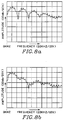
- Fig. 8 compares the frequency spectra for the drive signal of Fig. 6 and the modified drive signal of Fig. 7. Both achieve minimum energy content at a frequency substantially equal to 85 kilohertz, the standing wave resonant frequency for the specific ink jet print head and the particular ink employed.
- FIG. 9 is a plot of the pressure within the ink pressure chamber for the drive signal of Fig. 6 based upon this theoretical model.
- Fig. 10 is a plot of the pressure within the ink pressure chamber based upon the same model for the modified drive signal of Fig. 7.
- FIG. 11 shows theoretical model results for the drive signal of Fig. 6 and the modified drive signal of Fig. 7 repeated at a drop repetition rate of 8 kilohertz. It provides the threshold concentration of air dissolved in the ink, as a percentage of the ink's saturation concentration, for the onset of air bubble growth due to rectified diffusion for an air bubble of a given radius. According to the model, for ink having a concentration of dissolved air above 7 percent of the air saturation concentration of the ink, the drive signal of Fig.
- the threshold concentration for the onset of air bubble growth for a bubble with a 1 micron radius is 140 percent of the ink's saturation concentration.
- the modified drive signal of Fig. 7 reduces the pressure below ambient pressure applied to the ink residing within the ink pressure chamber of the ink jet print head and thereby inhibits the growth of air bubbles dissolved in the ink and the associated print quality degradation.
- Particular embodiments of the modified drive signal may, however, also result in wetting the orifice outlet of the ink jet print head. Ink jet print head performance problems associated with wetting the orifice outlet are described above. Empirical results indicate that this wetting of the orifice outlet occurs when the magnitude of the voltage of the refill pulse component is less than 0.7 times the magnitude of the voltage of the ejection pulse component.
- the present invention is applicable to ink jet print heads using a wide variety of inks.
- One example of a suitable phase change ink is disclosed in US Patent No 4,889,560, issued December 26, 1989 and entitled, "Phase Change Ink Carrier Composition and Phase Change Ink Produced Therefrom”.
Description
- The present invention relates to the operation of ink jet print heads and, in particular, to a method for generating a drive signal to control the operation of ink jet print heads.
- The present invention relates to printing with a drop-on-demand ("DOD") ink jet print head wherein ink drops are generated utilizing a drive signal that controls the operation of the ink jet print head to reduce rectified diffusion. Rectified diffusion is the growth of air bubbles dissolved in the ink from the repeated application of pressure pulses, at pressures below ambient pressure, to ink residing within the ink pressure chamber of the ink jet print head. Rectified diffusion results in print quality degradation over time. By controlling the operation of the ink jet print head, the drive signal may also simultaneously reduce rectified diffusion and enhance the consistency of drop flight time from the ink jet print head to print media over a wide range of drop ejection or drop repetition rates.
- Ink jet printers, and in particular DOD ink jet printers having ink jet print heads with acoustic drivers for ink drop formation, are well known in the art. The principle behind an ink jet print head of this type is the generation of a pressure wave in and the resultant subsequent emission of ink droplets from an ink pressure chamber through a nozzle orifice or ink drop ejection orifice outlet. A wide variety of acoustic drivers is employed in ink jet print heads of this type. For example, the drivers may consist of a pressure transducer formed by a piezoelectric ceramic material bonded to a thin diaphragm. In response to an applied voltage, the piezoelectric ceramic material deforms and causes the diaphragm to displace ink in the ink pressure chamber, which displacement results in a pressure wave and the flow of ink through one or more nozzles.
- Piezoelectric ceramic drivers may be of any suitable shape such as circular, polygonal, cylindrical, and annular-cylindrical. In addition, piezoelectric ceramic drivers may be operated in various modes of deflection, such as in the bending mode, shear mode, and longitudinal mode. Other types of acoustic drivers for generating pressure waves in ink include heater-bubble source drivers (so-called bubble or thermal ink jet print heads) and electromagnet-solenoid drivers. In general, it is desirable in an ink jet print head to employ a geometry that permits multiple nozzles to be positioned in a densely packed array, with each nozzle being driven by an associated acoustic driver.
- U.S. Patent No. 4,523,200 to Howkins describes one approach to operating an ink jet print head with the purpose of achieving high velocity ink drops free of satellites and orifice puddling and providing stabilized ink jet print head operation. In this approach, an electromechanical transducer is coupled to an ink chamber and is driven by a composite signal including independent successive first and second electrical pulses of opposite polarity in one case and sometimes separated by a time delay. The first electrical pulse is an ejection pulse with a pulse width which is substantially greater than that of the second pulse. The illustrated second pulse in the case where the pulses are of opposite polarity has an exponentially decaying trailing edge. The application of the first pulse causes a rapid contraction of the ink chamber of the ink jet print head and initiates the ejection of an ink drop from the associated orifice. The application of the second pulse causes rapid expansion of the ink chamber and produces early break-off of an ink drop from the orifice. There is no suggestion in this reference of controlling the position of an ink meniscus before drop ejection; therefore, problems in printing uniformly at high drop repetition rates would be expected.
- U.S. Patent No. 4,563,689 to Murakami et al. discloses an approach for operating an ink jet print head with the purpose of achieving different size drops on print media. In this approach, a preceding pulse is applied to an electromechanical transducer prior to a main pulse. The preceding pulse is described as a voltage pulse that is applied to a piezoelectric transducer in order to oscillate ink in the nozzle. The energy contained in the voltage pulse is below the threshold necessary to eject a drop. The preceding pulse controls the position of the ink meniscus in the nozzle and thereby the ink drop size. In Figs. 4 and 8 of Murakami et al., the preceding and main pulses are of the same polarity, but in Figs. 9 and 11, these pulses are of opposite polarity. Murakami et al. also mentions that the typical delay time between the start of the preceding pulse to the start of the main pulse is on the order of 500 microseconds. Consequently, in this approach, drop ejection would be limited to relatively low repetition rates.
- These prior art methods for operating ink jet print heads have difficulty achieving uniformly high print quality at high printing rates. Another potential problem associated with ink jet print heads is degradation in printing quality resulting from rectified diffusion. Rectified diffusion occurs when air bubbles dissolved in the ink grow from the repeated application of pressure waves or pulses, at pressures below ambient pressure, to ink residing within the ink pressure chamber of the ink jet print head. After a certain period of time, called the "onset-period," the printing quality degrades from continuously operating the ink jet print head in this manner. The onset-period depends on the drop repetition rate, and, prior to the initiation of continuous ink jet print head operation, on the amount of air dissolved in the ink, the ink viscosity, the ink density, the diffusivity of air in the ink, and the radii of the air bubbles dissolved in the ink. A need exists for a method of operating an ink jet print head that extends or eliminates the onset-period. A need also exists for a method that extends or eliminates the onset-period while simultaneously achieving high print quality at high printing rates.
- An object of the present invention is, therefore, to provide a method to control the operation of a DOD ink jet print head so that it may continue printing for an indefinite or extended period of time with little or no print quality degradation resulting from rectified diffusion.
- Another object of the present invention is to provide such a method to control the operation of the DOD ink jet print head so that it may print for a wide range of drop repetition rates, including high drop repetition rates.
- A drop-on-demand ink jet is described of the type having an ink chamber coupled to a source of ink, and ink drop forming orifice with an outlet, and in which the ink drop orifice is coupled to the ink chamber. An acoustic driver is used to produce a pressure wave in the ink to cause the ink to pass outwardly through the ink drop orifice and the outlet. The driver is operated to expand and contract he ink chamber to eject a drop of ink from the ink drop ejecting orifice outlet with the volume of the ink chamber first being expanded to refill the chamber with ink from a source of ink. During this expansion, ink is also withdrawn within the orifice toward the ink chamber and away from the ink drop ejection orifice outlet. A wait period is then established during which time the ink chamber is returning back to its original volume and the ink in the orifice to advance within the orifice away from the ink chamber and toward the ink drop ejection orifice outlet. In addition, the driver is then operated to contract the volume of the ink chamber to eject a drop of ink. Thus, a sequence of ink chamber expansion, a wait period, and ink chamber contraction is followed during the ejection of ink drops.
- In practice, of course, these drop ejection steps are repeated, for example at a high rate to achieve rapid printing. In addition, each of the waiting steps may comprise the step of waiting until the ink in the orifice advances to substantially the same position within the orifice to which the ink advances during the other waiting steps before the ink chamber is contracted to eject an ink drop.
- The waiting step may comprise the step of waiting until the ink advances to a position substantially at the ink drop ejection orifice outlet, but not beyond such orifice outlet, before contracting the volume of the ink chamber to eject a drop of ink.
- The contracting step may conveniently occur at a time when the ink is advancing toward that is, has a forward component of motion toward, the ink drop ejection orifice outlet.
- The driver may comprise a piezoelectric driver which is driven by a drive pulse including first and second pulse components separated by a wait period, the first and second pulse components being of an opposite polarity. These pulse components or electric drive pulses may be of a square wave or trapezoidal wave form.
- In accordance with the present invention, the dominant acoustic resonance frequency of the ink jet may be determined in a known manner. Typically, the most significant factor affecting the acoustic resonance frequency of the ink jet is the length of ink passage from the outlet of the ink chamber to the orifice outlet of the ink jet. The energy content of the complete electric drive pulse at various frequencies is also determined. The complete electric drive pulse in this case includes the refill pulse components, the drive pulse components, and wait periods utilized in ejecting a drop of ink. A standard spectrum analyzer may be used to determine the energy content of the drive pulse at various frequencies. The drive pulse is then adjusted, preferably by adjusting the duration of the wait period and the first or refill pulse component, such that a minimum energy content of the drive pulse exists at the dominant acoustic resonance frequency of the ink jet. If an ink jet of the type having an offset channel between the ink chamber and the ink drop ejection orifice outlet is used, the dominant acoustic resonance frequency corresponds to the standing wave resonance frequency through liquid ink in the offset channel of the ink jet. With this approach, the drive signal is tuned to the characteristics of the ink jet to avoid high energy components at the dominant resonance frequency of the ink jet.
- The drive pulse may be adjusted, if necessary, such that the minimum energy content on the drive pulse at a frequency which substantially corresponds to the dominant acoustic frequency of the ink jet is at least about 20 db below the maximum energy content of the drive pulse at frequencies other than the frequency which substantially corresponds to the dominant acoustic resonance frequency. In addition, the drive pulse may be adjusted, such that the maximum energy content of the drive pulse does not occur at a frequency which is sufficiently close (for example, less than 10 KHz) to any of the major resonance frequencies of the ink jet print head. Then major resonance frequencies include the meniscus resonance frequency, Helmholtz resonance frequency, piezoelectric drive resonance frequency and various acoustic resonance frequencies of the different channels and passageways forming the ink jet print head.
- The drive pulse may have refill and ejection pulse components of a trapezoidal shape in which the pulse components have a different rate of rise to their maximum amplitude than the rate of fall from the maximum amplitude. More specifically, the first electric drive pulse or refill pulse component may have a rise time from about 1 to about 4 microseconds, be at a maximum amplitude for from about 2 to about 7 microseconds, and may have a fall time from about 1 to about 7 microseconds. In addition, the wait period may be greater than about 8 microseconds. Furthermore, the second electric drive or eject pulse component may be within the same range of rise time, time at a maximum amplitude and fall time as the first electric drive pulse, but of opposite polarity. More specifically, the rise time of the first and second electric drive pulse component may more preferably be from about 1 to about 2 microseconds, the first and second electric drive pulse component may be at its maximum amplitude for from about 4 to about 5 microseconds, and the first and second electric drive pulse may have a fall time of from about 2 to about 4 microseconds, with the wait period being from about 15 to about 22 microseconds.
- The present invention is constituted by a method to control the operation of a DOD ink jet print head to reduce print quality degradation resulting from rectified diffusion. The invention modifies the method of operating an ink jet print head recited earlier.
- The method described earlier, summarized is a method of operating a DOD ink jet print head ("ink jet print head") having an ink pressure chamber coupled to a source of ink and having an ink drop ejecting orifice ("orifice") with an ink drop ejection orifice outlet ("orifice outlet"). The orifice of the ink jet print head is coupled to the ink pressure chamber. An acoustic driver operates to expand and contract the volume of the ink pressure chamber to eject a drop of ink from the orifice outlet. The acoustic driver applies a pressure wave to the ink residing within the ink pressure chamber to cause the ink to pass outwardly through the orifice and through the orifice outlet. The acoustic driver may comprise a piezoelectric ceramic material driven by voltage signal pulses. Upon application of a first voltage pulse, called the "refill pulse component", the acoustic driver operates to increase the volume of the ink pressure chamber through chamber expansion to refill the chamber with ink from the ink source. During ink pressure chamber expansion, ink is also drawn back within the orifice toward the ink pressure chamber and away from the orifice outlet. When the refill pulse component is no longer applied, a wait period state is then established during which time the ink pressure chamber returns to its original volume and the ink in the orifice advances within the orifice away from the ink pressure chamber and toward the orifice outlet. Upon application of a second voltage pulse of opposite relative polarity, called the "ejection pulse component", the acoustic driver then operates to reduce the volume of the ink pressure chamber through chamber contraction to eject a drop of ink. Thus, by applying these voltage pulses to the acoustic driver, a sequence of ink pressure chamber expansion, a wait period, and ink pressure chamber contraction accomplishes the ejection of ink drops.
- These steps are repeated at a high rate to achieve rapid printing. The refill pulse component, followed by the wait period state and the ejection pulse component comprise the drive signal. The refill pulse component and the ejection pulse component may be of a square wave or trapezoidal wave form.
- A preferred embodiment of the drive signal of the foregoing method comprises a bipolar electrical signal with refill and ejection pulse components varying about a zero amplitude reference voltage maintained during the wait period state; however, skilled persons would appreciate that the reference voltage need not have zero voltage amplitude. The drive signal may comprise pulse components of opposite relative polarity varying about a positive or negative reference voltage amplitude maintained during the wait period state. The drive signal is as mentioned earlier tuned to the characteristics of the ink jet printer head to avoid the presence of high energy components at the dominant acoustic resonant frequency of the ink jet print head, which may be determined in a known manner. Typically, the most significant factor affecting the dominant resonant frequency of the ink jet print head is the resonant frequency of the ink meniscus. A significant factor affecting the dominant acoustic resonant frequency of the ink jet print head is the length of the passage from the outlet of the ink pressure chamber to the orifice outlet of the ink jet print head. This passage is called the "offset channel".
- The drive signal is tuned to the characteristics of the ink jet print head, preferably by adjusting the time duration of the wait period state and the time duration of the first or refill pulse component, including the rise time and fall time of the refill pulse component. The rise time and fall time for the refill pulse component is the transition time from zero voltage to the voltage amplitude of the refill pulse component and from the voltage amplitude of the refill pulse component to zero voltage, respectively. A standard spectrum analyzer may be used to determine the energy content of the drive signal at various frequencies. After a tuning adjustment, a minimum energy content of the drive signal coincides with the dominant acoustic resonant frequency of the ink jet print head.
- The method of the present invention for operating an ink jet print head to reduce print quality degradation resulting from rectified diffusion is accomplished by modifying the pulse components of the drive signal so that the pressure applied to the ink residing within the ink pressure chamber of the ink jet print head, such pressure being below ambient pressure, is less than the threshold pressure magnitude that leads to rectified diffusion. One approach to accomplish this entails generating a drive signal to achieve high print quality and high printing rates in accordance with the previously set forth description of the first aspect of the invention. When this approach is followed, the pulse components of the drive signal are then modified to reduce print quality degradation resulting from rectified diffusion. To obtain the new drive signal from this initial drive signal, voltage amplitudes and time durations, including rise and fall times, of the refill and the ejection pulse components are, respectively, reduced and increased. Although the approach above begins with a drive signal to achieve high print quality and high printing rates in accordance with the description of the first aspect of the invention, any drive signal may be modified so that the pressure below ambient pressure applied to the ink residing within the ink jet print head is less than the threshold pressure magnitude that leads to rectified diffusion. Where the initial drive signal achieves high print quality and high printing rates in accordance with such aspect, to control the operation of the ink jet print head to reduce print quality degradation resulting from rectified diffusion, the magnitude of the voltage of the refill pulse component is reduced by fifty per cent, and the magnitude of the voltage of the ejection pulse component is reduced in relation to the newly established magnitude of the voltage of the refill pulse component. In a preferred form of the resulting drive signal, the magnitude of the voltage of the refill pulse component is less than 1.3 and greater than 1.15 of the magnitude of the voltage of the ejection pulse component. Furthermore, the relative polarities of the refill pulse component and the ejection pulse component may be reversed, depending upon the polarity of the pressure transducer.
- For the initial drive signal generated in accordance with the first aspect of the invention, the time durations of the refill pulse and the ejection pulse components, excluding rise and fall times, are then increased. In addition, the rise time and fall time for each of the refill and ejection pulse components are extended. The rise time and the fall time for each pulse component are the transition times, respectively, from zero voltage to the voltage amplitude of the pulse component and from the voltage amplitude to zero voltage. In a preferred form of the resulting drive signal, the rise and fall times for each of the refill and ejection pulse components are doubled.
- The above described adjustments of the voltage amplitudes, time durations, excluding rise and fall times, and rise and fall times of each pulse component are performed so that the frequency spectrum of the preferred embodiment of the drive signal has a minimum energy content at the dominant acoustic resonant frequency of the ink jet print head.
- The following specific description is intended to illustrate the invention, by way of example only, reference being made to the accompanying drawings, in which:-
- Fig. 1 is an illustration of one form of an ink jet print head with a print medium shown spaced from the ink jet print head.
- Fig. 2 illustrates one form of drive signal for an acoustic driver of an ink jet print head.
- Fig. 3 is a schematic illustration, showing in cross section, of one type of ink jet print head capable of being operated in accordance with the method of the present invention.
- Figs. 4a, 4b, and 4c, for various wait periods, illustrate a simulation of the change in shape of an ejected ink column at a point near breakoff of an ink drop from the column when an ink jet print head of the type illustrated in Fig. 3 is actuated by a single drive signal of the type shown in Fig. 2.
- Fig. 5 is a plot of drop flight time versus drop ejection rate for the continuous operation of an ink jet print head of the type illustrated in Fig. 3 when actuated by a drive signal of the type shown in Fig. 2, where the time duration of the ejection pulse component, including rise and fall times, has been adjusted so that the minimum energy content of the drive signal coincides with the dominant acoustic resonant frequency of the ink jet print head.
- Fig. 6 illustrates another form of drive signal for an acoustic driver of an ink jet print head of the type shown in Fig. 3, with values provided for the time durations of the refill and ejection pulse components, including rise and fall times, the time duration of the wait period, and the voltage amplitudes of the refill and ejection pulse components.
- Fig. 7 illustrates a drive signal for reducing rectified diffusion in accordance with the present invention for an acoustic driver of an ink jet print head of the type illustrated in Fig. 3.
- Fig. 8 illustrates the frequency spectra of the drive signal in Fig. 6 and the drive signal in Fig. 7 with minimum energy for both drive signals occurring at about 85 kilohertz, the dominant acoustic resonant frequency of the ink jet print head.
- Fig. 9 is a time-based plot, for a theoretical model of an ink jet print head of the type illustrated in Fig. 3, of the pressure applied to ink residing within the ink pressure chamber of an ink jet print head operated by the drive signal of Fig. 6.
- Fig. 10 is a time-based plot, for a theoretical model of an ink jet print head of the type illustrated in Fig. 3, of the pressure applied to ink residing within the ink pressure chamber of an ink jet print head operated by the drive signal of Fig. 7.
- Fig. 11 is a plot, for a theoretical model of rectified diffusion, of the threshold concentration of air dissolved in ink for the onset of air bubble growth resulting from rectified diffusion versus air bubble radius, the threshold concentration of air being expressed as a percentage of the saturation concentration of the ink.
- FIG 12 is a plot of the drop speed as a function of drop ejection rate for the continuous operation of an ink jet of the type shown in FIG 3 actuated by a drive pulse having only the eject pulse component "C" of the wave form of FIG 2.
- FIG 13 is a plot of the drop flight time as a function of drop ejection rate for the continuous operation of an ink jet of the type illustrated in FIG 3 actuated by a drive pulse having only the eject pulse component "C" of the wave form of FIG 2 and in which the eject pulse has been optimized for a specific ink jet print head.
- With reference to Fig. 1, a DOD ink
jet print head 9 is illustrated with an internal ink pressure chamber (not shown in this figure) coupled to anink source 11. The inkjet print head 9 has one or more ink drop ejection orifice outlets ("orifice outlets") 14, of whichoutlets orifice outlets 14 during ink drop formation. Ink drops travel in a direction along a path fromorifice outlets 14 toward aprint medium 13, which is spaced from the orifice outlets. A typical ink jet printer includes a plurality of ink pressure chambers each coupled to one or more of the respective orifices and orifice outlets. - An
acoustic drive mechanism 36 is utilized for generating a pressure wave or pulse, which is applied to the ink residing within the ink pressure chamber to cause the ink to pass outwardly through the orifice and its associatedorifice outlet 14. Theacoustic driver 36 operates in response to signals from asignal source 37 to cause the pressure waves applied to the ink. - The invention has particular applicability and benefits when piezoelectric ceramic drivers are used in ink drop formation. One preferred form of an ink jet print head using this type of acoustic driver is described in detail in US Patent Application No 07/430,213 (corresponding to European Patent Application No 90 311977.4). However, it is also possible to use other forms of ink jet printers and acoustic drivers in conjunction with the present invention. For example, electromagnet-solenoid drivers, as well as other shapes of piezoelectric ceramic drivers (eg, circular, polygonal, cylindrical, and annular-cylindrical) may be used. In addition, various modes of deflection of piezoelectric ceramic drivers may also be used, such as bending mode, shear mode, and longitudinal mode.
- With reference to Fig. 3, one form of ink
jet print head 9 in accordance with the disclosure of the patent application just referred to has abody 10 which defines anink inlet 12 through which ink is delivered to the ink jet print head. Thebody 10 also defines an orifice outlet ornozzle 14 together with anink flow path 28 from theink inlet 12 to thenozzle 14. In general, an ink jet print head of this type would preferably include an array ofnozzles 14 which are proximately disposed, that is closely spaced from one another, for use in printing drops of ink onto a print medium. - Ink entering the
ink inlet 12, eg, fromink supply 11 as shown in Fig. 1, passes to anink supply manifold 16. A typical colour ink jet print head has at least four such manifolds for receiving, respectively, black, cyan, magenta, and yellow ink for use in black plus three color subtraction printing. However, the number of such ink supply manifolds may be varied depending upon whether a printer is designed to print solely in black ink or with less than a full range of color. Fromink supply manifold 16, ink flows through anink inlet channel 18, through anink inlet 20 and into anink pressure chamber 22. Ink leaves theink pressure chamber 22 by way of an inkpressure chamber outlet 24 and flows through anink passage 26 to thenozzle 14 from which ink drops are ejected.Arrows 28 diagram this ink flow path. - The
ink pressure chamber 22 is bounded on one side by aflexible diaphragm 34. The pressure transducer, in this case a piezoelectricceramic disc 36 secured to thediaphragm 34, as by epoxy, overlays theink pressure chamber 22. In a conventional manner, the piezoelectricceramic disc 36 has metal film layers 38 to which an electronic circuit driver, not shown in Fig. 3, but indicated at 37 in Fig. 1, is electrically connected. Although other forms of pressure transducers may be used, the illustrated transducer is operated in its bending mode. That is, when a voltage is applied across the piezoelectric ceramic disc, the disc attempts to change its dimensions. However, because it is securely and rigidly attached to thediaphragm 34, bending occurs. This bending displaces ink in theink pressure chamber 22, causing the outward flow of ink through theink passage 26 and to thenozzle 14. Refill of theink pressure chamber 22 following the ejection of an ink drop can be augmented by reverse bending of thepressure transducer 36. - In addition to the
ink flow path 28 described above, an optional ink outlet or purgingchannel 42 is also defined by thebody 10 of inkjet print head 9. The purgingchannel 42 is coupled to theink passage 26 at a location adjacent to, but interior to, thenozzle 14. The purgingchannel 42 communicates fromink passage 26 to an outlet or purgingmanifold 44 which is connected by apurging outlet passage 46 to apurging outlet port 48. The purgingmanifold 44 is typically connected bysimilar purging channels 42 tosimilar ink passages 26 associated withmultiple nozzles 14. During a purging operation, ink flows in a direction indicated byarrows 50, through purgingchannel 42, purgingmanifold 44, purgingoutlet passage 46 and to thepurging outlet port 48. - To facilitate manufacture of the ink jet print head of FIG 3, the
body 10 is preferably formed of plural laminated plates or sheets, such as of stainless steel. These sheets are stacked in superposed relationship. In the illustrated FIG 3 form of ink jet print head, these sheets or plates include a diaphragm plate 60, which forms the diaphragm and also defines the ink inlet 12 and purging outlet 48; and ink pressure chamber plate 62, which defines the ink pressure chamber 22, a portion of the ink supply manifold, and a portion of the purging passage 48; a separator plate 64, which defines a portion of the ink passage 26, bounds one side of the ink pressure chamber 22, defines the inlet 20 and outlet 24 to the ink pressure chamber, defines a portion of the ink supply manifold 16 and also defines a portion of the purging passage 46; an ink inlet plate 66, which defines a portion of the passage 26, the inlet channel 18, and a portion of the purging passage 46; another separator plate 68 which defines portions of the passages 26 and 46; an offset channel plate 70, which defines a major or offset portion 71 of the passage 26 and a portion of the purging manifold 44; a separator plate 72 which defines portions of the passage 26 and purging manifold 44; an outlet plate 74 which defines the purging channel 42 and a portion of the purging manifold; a nozzle plate 76 which defines the nozzles 14 of the array; and an optional guard plate 78 which reinforces the nozzle plate and minimizes the possibility of scratching or other damage to the nozzle plate. - More or fewer plates than illustrated may be used to define the various ink flow passageways, manifolds and pressure chambers. For example, multiple plates may be used to define an ink pressure chamber instead of a single plate as illustrated in FIG 3. Also, not all the various features need be in separate sheets or layers of metal.
- Exemplary dimensions for elements of the ink jet print head of Fig. 3 are set forth in Table 1 below.
TABLE 1 Representative Dimensions and Resonant Characteristics For Figure 3 Ink Jet Print Heads Feature Cross Section Length Frequency of Resonance Ink Supply Channel 18008"x0.010" 0.268" 60- 70KHz Diaphragm Plate 60 0.110"dia. 0.004" 160- 180KHz Body Chamber 22 0.110"dia. 0.018" Separator Plate 640.040"x0.036" 0.022" Offset Channel 710.020"x0.036" 0.116" 65- 85KHz Purging Channel 42 0.004"x0.010" 0.350" 50- 55KHz Orifice Outlet 14 50-70µm 60-76µm 13-18KHz - The various layers forming the ink jet print head may be aligned and bonded in any suitable manner, including by the use of suitable mechanical fasteners. However, one approach for bonding the metal layers is described in US Patent No 4,883,219 to Anderson, et al, and entitled "Manufacture of Ink Jet Print Heads by Diffusion Bonding and Brazing."
- One form of drive signal for controlling the operation of ink jet print heads utilizing acoustic drivers to achieve high print quality and high printing rates is illustrated in Fig. 2. This particular drive signal is a bipolar
electrical pulse 100 with arefill pulse component 102 and anejection pulse component 104. Thecomponents pulse components wait period 106 is indicated as "B" in Fig. 2. The relative polarities of thepulse components - A preferred embodiment of the drive signal comprises a bipolar electrical signal with refill and ejection pulse components varying about a zero voltage amplitude maintained during the
wait period 106; however, the invention is not limited to this particular embodiment. The drive signal may comprise pulse components of opposite relative polarity varying about a positive or negative reference voltage amplitude maintained during the wait period state. - In the operation of an ink jet print head, utilizing the drive signal described above, the
ink pressure chamber 22 expands upon the application of therefill pulse component 102 and draws ink into theink pressure chamber 22 from theink source 11 to refill theink pressure chamber 22 following the ejection of a drop. As the voltage falls toward zero at the end of therefill pulse component 102, theink pressure chamber 22 begins to contract and moves the ink meniscus forward in the ink orifice 103 (Fig. 3) toward theorifice outlet 14. During the wait period "B", the ink meniscus continues toward theorifice outlet 14. Upon the application of theejection pulse component 104, theink pressure chamber 22 is rapidly constricted to cause the ejection of a drop of ink. After the ejection of the drop of ink, the ink meniscus is once again drawn back into theink orifice 103 away from theorifice outlet 14 as a result of the application of therefill pulse component 102. The time duration of the refill pulse component, including rise and fall times, is less than the time required for the ink meniscus to return to a position adjacent to theorifice outlet 14 for ejection of a drop of ink. - Typically, the time duration of the
refill pulse component 102, including rise time and fall time, is less than one-half of the time period associated with the resonant frequency of the ink meniscus. More preferably, this duration is less than about one-fifth of the time period associated with the resonant frequency of the ink meniscus. The resonant frequency of an ink meniscus in an orifice of an ink jet print head can be easily calculated from the properties of the ink, including the volume of the ink inside the ink jet print head, and the dimensions of the orifice in a known manner. - As the time duration of the wait period "B" increases, the ink meniscus moves closer to the
orifice outlet 14 at the time theejection pulse component 104 is applied. In general, the time duration of thewait period 106 and of theejection pulse component 104, including the rise time and fall time of the ejection pulse component, is less than about one-half of the time period associated with the resonant frequency of the ink meniscus. For controlling the operation of an ink jet print head to achieve high print quality and high printing rates by the drive signal described, typical time periods associated with the resonant frequency of the ink meniscus range from about 50 microseconds to about 160 microseconds, depending upon the configuration of the specific ink jet print head and the particular ink. - The
pulse components conventional signal source 37 may be used to generate pulses of this shape. Other pulse shapes may also be used. In general, a suitablerefill pulse component 102 is one which results in increasing the volume of theink pressure chamber 22 through the expansion of the chamber to refill the chamber with ink from theink source 11 while withdrawing the ink in theink orifice 103 back toward theink pressure chamber 22 and away from theorifice outlet 14. Thewait period 106 is a period during which essentially zero voltage is applied to the acoustic driver. It comprises a period during which theink pressure chamber 22 is allowed to return back to its original volume due to contraction of the chamber so as to allow the ink meniscus in theink orifice 103 to advance within the orifice away from theink pressure chamber 22 and toward theorifice outlet 14. Theejection pulse component 104 is of a shape which causes a rapid contraction of theink pressure chamber 22 following thewait period 106 to reduce the volume of the chamber and eject a drop of ink. - A drive signal composed of pulses of the form shown in Fig. 2 is repeatedly applied to cause the ejection of ink drops. One or more pulses may be applied to cause the formation of each drop, but, in a preferred embodiment, one such composite drive signal is used to form each of the drops. In addition, the time duration of the
wait period 106 is typically set to allow the ink meniscus in theink orifice 103 to advance to substantially the same position within the orifice during each wait period before contraction of theink pressure chamber 22 to eject a drop. It is preferable that the ink meniscus have a remnant of forward velocity withinink orifice 103 towardorifice outlet 14 at the time of arrival of the pressure pulse in response to theejection pulse component 104 of Fig. 2. Under these conditions, the fluid column propelled out of the ink jet print head properly coalesces into a drop to thereby minimize the formation of satellite drops. The ink meniscus should not advance to a position beyond theorifice outlet 14. If ink is allowed to project beyond theorifice outlet 14 for a substantial period of time before theejection pulse 104 is applied, it may wet the surface surrounding the orifice outlet. This wetting may cause an asymmetric deflection of ink drops and non-uniform drop formation as the various drops are formed and ejected. By positioning the ink meniscus at substantially the same position prior to the pressure pulse, uniformity of drop flight time to the print medium is enhanced over a wide range of drop ejection rates. - In addition, it is preferable that the ink meniscus have a remnant of forward velocity within the
orifice 103 towardoutlet 14 at the time of arrival of the pressure pulse in response to theeject pulse component 104 of FIG 2. Under these conditions, the fluid column propelled out of the ink jet print head properly coalesces into the drop to thereby minimize the formation of satellite drops. Theeject pulse component 104 causes thediaphragm 34 of the pressure transducer to rapidly move inwardly toward theink chamber 22 and results in a sudden pressure wave. This pressure wave ejects the drop of ink presented at the orifice outlet at the end of the wait period. Following the termination of theeject pulse component 104, diaphragm returns toward its original position and, in so doing, initiates a negative pressure wave which assists in breaking off an ink drop. - Exemplary durations of the various pulse components for achieving high print quality and high printing rates are 5 microseconds for the "A" portion of the
refill pulse component 102, with rise and fall times of respectively 1 microsecond and 3 microseconds; a wait period "B" of 15 microseconds; and anejection pulse component 104 with a "C" portion of 5 microseconds and with rise and fall times like those of therefill pulse component 102. As stated earlier, Fig. 2 demonstrates the representative shape of the drive signal, but does not provide representative values for its various attributes. To achieve high print quality and high print rates, it may sometimes be advantageous to reduce the duration of these time periods so that the fluidic system may be reinitialized as quickly as possible, thereby making faster printing rates possible. However, this ignores the print quality degradation resulting from rectified diffusion that reducing the duration of these time periods may cause or further degrade. An alternative method to increase the drop repetition rate for the drive signal comprises reducing the time duration from the trailing edge of the ejection pulse component to the leading edge of the refill pulse component. This method has the advantage that it does not affect the time durations of the pulse components, including rise and fall times. - Fig. 4 illustrates a simulation of the change in shape of an ejected ink column when an ink jet print head of the type illustrated in Fig. 3 is actuated by a drive signal composed of the exemplary durations above. Figs. 4a, 4b, and 4c demonstrate the effect of varying the
wait period 106. As shown in Fig. 4a, with the time duration of the wait period "B" at 18 microseconds, the main volume ofink 120 forms a spherical head which is connected to along tapering tail 122 with drop breakoff occurring at alocation 124 between the tail of this filament and theorifice outlet 14. After drop breakoff thetail 122 starts to coalesce into thehead 120 and does not form a spherical drop by the time it reaches the print medium. However, due to the relatively high speed of the ink column with respect to the print medium the resulting spot on the print medium is nearly spherical. - As shown in Fig. 4b, with a
wait period 106 of 8 microseconds, thedrop breakoff point 124 is adjacent to the main volume ofink 120 and results in a cleanly formed drop. In this case, thetail 122 of the drop breaks off subsequently to theorifice outlet 14 and forms a satellite drop which moves at a relatively smaller velocity than that of the main drop. Consequently, themain drop 120 andsatellite drop 122 form two separate spots on the print medium. - With reference to Fig. 4c, and with a
wait period 106 of zero microseconds, thedrop breakoff point 124 occurs adjacent to themain drop volume 120. However, the remainingink filament 122 has weak points, indicated at 126 and 128, corresponding to potential locations at which the filament may break off and form satellite drops. - The Fig. 4 illustrations are the result of a theoretical model of the operation of the ink jet print head of Fig. 3 using the form of the drive signal shown in Fig. 2. The Fig. 4 illustrations show only the upper half of the formed drop above the center line of the
ink orifice 103 in each of these figures. - Neither a pull back or refill pulse, such as
pulse component 102 alone, nor an eject pulse, such ascomponent 104 alone, results in satisfactory print performance, even though drop ejection may be accomplished by either of thepulse components refill pulse component 104 would tend to severely limit the drop ejection speed, such as to about 3.5 meters per seconds or less. In addition, increasing the magnitude or duration of therefill pulse components 104, in an attempt to increase drop speed, would result in pulling the meniscus so far into the upstream edge of theink orifice 103 that ingestion of air bubbles may result. High drop speeds are desirable, such as on the order of 6 meters per second or more, to increase the capacity of an ink jet printer to operate at high drop ejection rates. - As shown in FIG 12, the use of an
eject pulse component 106 only, without the refill pulse and wait period components, results in a rhythmical variation in drop speed with changing drop ejection rates. The frequency of the rhythmical variations may be verified from the information in Table 1 to be the same as that of the reverberation resonance in the channel sections forming the ink flow path between theink chamber 22 and theink orifice outlet 14. As shown in FIG 13, an eject pulse component only drive signal may be designed which smooths the speed or flight time variations by using a drive pulse with a frequency spectrum which deliberately removes energy from the reverberations. However, in this case, the ink volume per drop declines as the ejection rate increases. In other words, the ink chamber does not adequately refill between drop ejections at all drop ejection rates. A further disadvantage is that, since the same amount of energy is imparted by the piezoelectric element to every drop ejected regardless of refilling, the smaller drops tend to travel at faster speeds. Thus, as shown in FIG 13, the drop speed generally increases (corresponding to a decrease in flight drop time) as the drop ejection rate increases, although the rhythmical drop speed variations prominent in FIG 12 are absent. - The deficiencies of the eject only pulse component drive approach, are overcome by actuating a
refill pulse component 104 first to actively refill theink chamber 22. In addition, the offsetchannel 71 in FIG 3 is also refilled if the ink jet print head is of a design having such a channel. The ink chamber may be passively refilled fully be enlarging theink inlet refill pulse component 104. However, in this case upon movement of the diaphragm inwardly to cause a drop to issue from thedrop ejection orifice 14, the pressure pulse set up in theink chamber 22 would flow into the conduit leading to theorifice 26 and also into theink inlet body chamber 22 andpassageway 26 from pressure pulse disturbances originating in the ink reservoir or manifold 16 if the jet is a member of an array. This isolation is progressively reduced as theinlet opening 20 is enlarged. A balance is thus struck among the size of theink inlet 20, the strength of the refill pulse component 102 (FIG 2) and the strength of theeject pulse component 104. A strongrefill pulse component 102 will pull ink through the inlet opening 20 into thepressure chamber 22. Too strong of a refill pulse component will cause the ingestion of a bubble through the orifice outlet. Likewise, too strong of aneject pulse component 104 will eject more ink in a single drop than the refill pulse component may be able to draw through theink inlet 20. One preferred interrelationship of these parameters is described in Table 1 and in the exemplary pulse component durations mentioned above. - The inclusion of a
refill pulse component 102 in the drive signal tends to draw ink back from the external surface surrounding theorifice outlet 14. This action minimizes the possibility of ink wetting the surface surrounding the outlet and distorting the travel or breakoff of ink drops at the orifice outlet. The preferred time duration of the wait period "B" is a combined function of the time for the retracted ink meniscus inink orifice 103 to reach theorifice outlet 14 and the velocity of the ink at the instant of arrival of the pressure pulse initiated by theejection pulse component 104. It is desired that the retracted ink meniscus reach theorifice outlet 14 with waning velocity just before the pressure pulse from theejection pulse component 104 is applied. - Fig. 5 depicts the situation in which the ink jet print head is operated in the manner described to achieve high print quality and high printing rates. Fig. 5 is a plot of the drop flight time for an ink jet print head of the type shown in Fig. 3 versus drop ejection rate and is substantially constant over a range of drop ejection rates through and including ten thousand drops per second. In this Fig. 5 example, the print medium was 1 mm from the ink jet print
head orifice outlet 14, and drop speeds in excess of 6 meters per second were achieved. As also shown in Fig. 5, a maximum deviation of 30 microseconds was observed over an ink jet drop ejection rate ranging from 1,000 drops per second to 10,000 drops per second. In addition, at below 8,500 drops per second, this deviation was much less pronounced. Thus, by suitably selecting a drive signal having arefill pulse component 102, await period 106, and anejection pulse component 104, substantially constant drop flight times can be achieved over a wide range of drop ejection rates. Substantially constant drop flight times result in high print quality. - In addition, the drop speeds are relatively fast with uniform drop sizes being available. The drop trajectories are substantially perpendicular to the orifice face plate for all drop ejection rates, inasmuch as the
refill pulse component 102 of the drive signal assists in reducing wetting of the external surface surrounding theorifice outlet 14 which may cause a deflection of the ejected drops from a desired trajectory. Moreover, satellite drop formation is minimized because this drive signal allows high viscosity ink, such as hot melt ink, within the conduit of theink orifice 103 to behave as an intracavity acoustic absorber of pressure pulses reverberating in the offsetchannel 71 of an ink jet print head of the type shown in Fig. 3. The relatively simple drive signal of the type illustrated in Fig. 2 may be achieved with conventional off-the-shelf digital electronic drive signal sources. - A preferred relationship between the
drive pulse components wait period 106 of at least as great as and preferably greater than about 8 microseconds, uniform and consistent ink drop formation has been achieved. Shorter wait periods have been observed in some cases to increase the probability of formation of satellite drops. Preferably the time duration of the refill or expandingpulse component 102, including rise time and fall time, is no more than about 16 to 20 microseconds. A greater refill pulse component time duration increases the possibility of ingesting bubbles into theorifice outlet 14. To achieve high print quality and high printing rates, the refill pulse component time duration, including rise time and fall time, need be no longer than necessary to replace the ink ejected during ink drop formation. Shorter refill pulse component time durations increase the drop repetition rate which may be achieved. However, as indicated, this ignores the effect that these shorter refill pulse component time durations may have upon print quality degradation resulting from rectified diffusion. In general, therefill pulse component 102 has a time duration, including rise time and fall time, to achieve high print quality and high printing rates of no less than about 7 microseconds. The time duration of theejection pulse component 104, including rise time and fall time, to achieve high print quality and high printing rates is typically no more than about 16 to 20 microseconds and no less than about 6 microseconds. - Within these drive signal parameters that control the operation of an ink jet print head to achieve high print quality and high printing rates, ink jet print heads of the type shown in Fig. 3 have been operated at drop ejection rates through and including 10,000 drops per second, and higher, and at drop ejection speeds in excess of 6 meters per second. The drop speed nonuniformity has been observed at less than 15 percent over continuous and intermittent drop ejection conditions. As a result, the drop position error is much less than one-third of a pixel at 11.81 drops per mm printing with an 8 kilohertz maximum printing rate. In addition, a measured drop volume of 170 picoliters of ink per drop ± 15 picoliters (over the entire operating range of 1,000 to 10,000 drops per second) has been observed and is suitable for printing at 11.81 drops per mm addressability when using hot melt inks. Additionally, minimal or no satellite droplets occur under these conditions.
- As shown in Fig. 2, the first pulse component,
refill component 102, reaches a voltage amplitude and is maintained at this amplitude for a period of time prior to termination of the first or refill pulse component. In addition, the second orejection pulse component 104 reaches a negative voltage amplitude and is maintained at this amplitude for a period of time prior to termination of the second pulse. Although this may be varied, in the illustrated form to achieve high print quality and high printing rates, these drive pulse components are trapezoidal in shape and have a different rise time to their respective voltage amplitudes from the fall time from their respective voltage amplitudes. In a drive signal to achieve high print quality and high printing rates, the twopulse components wait period 106 being greater than about 8 microseconds. In an alternative drive signal to achieve high print quality and high printing rates, the rise time of the first pulse is about 2 microseconds, the first pulse achieves its voltage amplitude from about 3 microseconds to about 7 microseconds, the first pulse has a fall time from about 2 microseconds to about 4 microseconds, and thewait period 106 is from about 15 microseconds to about 22 microseconds. In addition, in this case theejection pulse component 104 is like therefill pulse component 102, except of opposite relative polarity. - It should be noted that to achieve high print quality at high printing rates these time durations may be varied for different ink jet print head designs and different inks. Again, it is desirable for the ink meniscus to be traveling forward and to be at a common location at the occurrence of each pressure wave resulting from the application of the
ejection pulse component 104. The parameters of the drive signal may be varied to achieve these conditions. - It has also been discovered that optimal print quality and printing rate performance is achieved when the drive signal is shaped so as to provide a minimum energy content at the dominant acoustic resonant frequency of the ink jet print head. That is, the dominant acoustic resonant frequency of the ink jet print head can be determined in a well-known manner. The dominant resonant frequency of the ink jet print head typically corresponds to the resonant frequency of the ink meniscus. When an ink jet print head of the type shown in Fig. 3 is used with an offset
channel 71, the dominant acoustic resonant frequency in general corresponds to the standing wave resonant frequency through the liquid ink in the offset channel. By using a drive signal with an energy content which is at a minimum at the dominant acoustic resonant frequency of the ink jet print head, reverberations at this dominant acoustic resonant frequency are minimized, such reverberations otherwise potentially interfering with the uniformity of flight time of drops from the ink jet print head to the print medium. - In general, to assist in adjusting the drive signal to achieve high print quality and high printing rates, a Fourier transform or spectral analysis is performed of the complete drive signal. The complete drive signal is an entire set of pulses used in the formation of a single ink drop. In the case of a drive signal of the type shown in Fig. 2, the complete signal includes the
refill pulse component 102, thewait period 106, and theejection pulse component 104. A conventional spectrum analyzer may be used in determining the energy content of the drive signal at various frequencies. This energy content will vary with frequency from highs or peaks to valleys or low points. A minimum energy content portion of the drive signal at certain frequencies is substantially less than the peak energy content at other frequencies. For example, a minimum energy content may be at least about 20 dB below the maximum energy content of the drive signal at other frequencies. - The drive signal may be adjusted to shift the frequency of this minimum energy content to be substantially equal to the dominant acoustic resonant frequency of the ink jet print head. With the drive signal adjusted in this manner, the energy of the drive signal at the dominant acoustic resonant frequency is minimized. As a result, the effect of resonant frequencies of the ink jet print head on ink drop formation is minimized. Although not limited to any specific approach, a preferred method of adjusting the drive signal to achieve high print quality and high printing rates comprises the step of adjusting the time duration of the first pulse, or refill
pulse component 102, including rise time and fall time, and of thewait period 106. These pulse components are adjusted in duration until there is a minimum energy content of the drive signal at the frequency which is substantially equal to the dominant acoustic resonant frequency of the ink jet print head. - Continuously operating an ink jet print head for a long period of time may lead to print quality degradation resulting from rectified diffusion, particularly when such operation occurs at high drop repetition rates. Rectified diffusion is the growth of air bubbles dissolved in the ink caused by the repeated application of pressure pulses, at pressures below ambient pressure, to the ink residing within the ink pressure chamber of the ink jet print head. When the ink jet print head operates in the open atmosphere the ambient pressure generally corresponds to atmospheric pressure. Air bubble growth will result from the application of pressures below atmospheric pressure to the ink residing within the ink pressure chamber of the ink jet print head, as described. An aspect of the present invention reduces print quality degradation resulting from rectified diffusion. A preferred embodiment may simultaneously achieve uniformly high print quality at high printing rates.
- The period of time necessary for the onset of print quality degradation, called the onset-period, depends on the drop repetition rate and, prior to the initiation of continuous operation of the ink jet print head, on the amount of air dissolved in the ink, the ink viscosity, the ink density, the diffusivity of the air in the ink, and the radii of the air bubbles dissolved in the ink. Air bubble growth results when, for pressures below ambient pressure, pressure pulse magnitudes occur above a threshold pressure magnitude at a drop repetition rate above a threshold drop repetition rate. With ink having an amount of dissolved air well below the saturation level of the ink for dissolved air, it will typically take 10 minutes of continuous operation of the ink jet print head at a drop repetition rate of 8 kilohertz before the impairment of ink drop ejection and the associated print quality degradation. For ink saturated with dissolved air, it will typically take only 30 seconds at the same drop repetition rate for print quality degradation to occur.
- The present invention inhibits air bubble growth in DOD ink jet print heads by controlling the operation of the ink jet print head with a drive signal that, for pressures below ambient pressure, applies pressure to the ink at magnitudes less than the threshold pressure magnitude that leads to the air bubble growth. In a preferred embodiment, a drive signal that achieves high print quality at high printing rates is modified in accordance with the present invention so that the resulting drive signal simultaneously achieves uniformly high print quality for a wide range of drop ejection rates, including high rates.
- The resulting drive signal applies pressure below ambient pressure to the ink residing within the ink pressure chamber of the ink jet print head at magnitudes less than the threshold pressure magnitude that leads to rectified diffusion, while simultaneously achieving high print quality at high printing rates. Nonetheless, other embodiments of the present invention may reduce print quality degradation resulting from recitified diffusion without achieving high print quality at high printing rates. For example, the present invention is not limited to a bipolar drive signal; however, to accomplish the preferred embodiment, one may obtain a drive signal to control the operation of an ink jet print head by the method previously described, and make modifications to this drive signal that will result in the application of lower pressure magnitudes, at pressures below ambient pressure, to the ink residing within the ink pressure chamber of the ink jet print head. Although the preferred embodiment involves modifications to both the refill pulse component and the ejection pulse component, other embodiments of the present invention may only modify one of these pulse components. In the modified drive signal, the refill pulse component and the ejection pulse component have greater time durations, excluding rise and fall times, at their respective voltage amplitudes. In addition, the rise times and the fall times of the refill pulse component and the ejection pulse component of the modified drive signal are extended. This avoids inducing large pressure pulses below ambient pressure that occur in the ink pressure chamber with rapid changes in the voltage amplitude applied to the acoustic driver of the ink jet print head. In the preferred embodiment both the rise time and the fall time of the pulse components are extended; however, extending at least one of these times will also reduce print quality degradation resulting from rectified diffusion. The respective voltages of the refill pulse component and the ejection pulse component are also reduced in magnitude. Furthermore, the magnitude of the voltage of the refill pulse component is reduced with respect to the magnitude of the voltage of the ejection pulse component to obtain the modified drive signal.
- Reducing the voltage amplitude of the refill pulse component relative to that of the ejection pulse component will reduce the magnitude of the pressures below ambient pressure applied to the ink residing within the ink pressure chamber of the ink jet print head; however, where the ink jet print head operates at high drop repetition rates, such voltage amplitude reduction may result in another problem also associated with prolonged operation of an ink jet print head.
- At high drop repetition rates the ink jet print head operates at high ink flow rates. During such operation, the refill pulse component serves various purposes, including providing adequate refill of the ink pressure chamber by overcoming the flow resistances present primarily through the inlet channel of the ink jet print head. The refill pulse component serves this purpose at low repetition rates as well; however, the ink flow resistances become more pronounced at high drop repetition rates due to the associated high ink flow rates. These flow resistances also become stronger in an ink jet print head array where several ink jet print heads are supplied ink through a common conduit. If all the ink jet print heads sharing the conduit are simultaneously operating at a high drop repetition rate the associated flow resistance may become significant. In such a situation, after prolonged operation, the ink jet print head array exhibits decreasing ink flow over time and the ink pressure chamber does not adequately refill. Ultimately, one or more ink jet print heads stop ejecting ink altogether and reach a state called "starvation."
- One way to avoid "starvation" and provide adequate refill of the ink pressure chamber involves increasing the voltage amplitude of the refill pulse component relative to the voltage amplitude of the ejection pulse component. Thus, a potential trade-off exists between (1) lowering the relative voltage amplitude of the refill pulse component to reduce rectified diffusion by lowering the magnitude of the pressures below ambient pressure applied to the ink residing in the ink pressure chamber and (2) raising the relative voltage amplitude of the refill pulse component to avoid starvation. The preferred operating range of the ink jet print head regarding these relative voltage amplitudes may be characterized mathematically at the ratio of the magnitude of the voltage of the refill pulse component to the magnitude of the voltage of the ejection pulse component. This ratio is termed the "aspect ratio." The preferred embodiment of the present invention to ensure prolonged operation of an ink jet print head array at high drop repetition rates has an aspect ratio between 1.15 and 1.3. Other embodiments may provide prolonged operation for aspect ratios between 1.0 and 1.4.
- Controlling the operation of an ink jet print head by the modified drive signal described above will result in high print quality at high printing rates as previously described while simultaneously reducing print quality degradation resulting from rectified diffusion. For example, the drive signal illustrated in Fig. 6 achieves high print quality while actuating an ink jet print head of the type illustrated in Fig. 3 at 10 kilohertz. The drive signal illustrated in Fig. 7 achieves high print quality and reduces print quality degradation from rectified diffusion by actuating an ink jet print head of the type illustrated in Fig. 3 at 8 kilohertz.
- Fig. 6 shows a drive signal of the type illustrated in Fig. 2 for an acoustic driver of a specific ink jet print head. It provides values for the time durations at the respective voltage amplitudes of the refill pulse component and the ejection pulse component, for the time duration of the wait period, and for the respective voltage amplitudes of the refill pulse component and the ejection pulse component. It also provides rise and fall times for the pulse components.
- Fig. 7 shows a modified drive signal in accordance with the present invention for the acoustic driver of the same ink jet print head. Like the drive signal of Fig. 6, the modified drive signal of Fig. 7 consists of a refill pulse component, followed by a wait period and an ejection pulse component. In Fig. 7 the magnitude of the voltage of the refill pulse component is approximately 1.4 times the magnitude of the voltage of the ejection pulse component. The magnitude of the voltage of the refill pulse component of Fig. 7 is approximately 50 percent of the magnitude of the voltage shown for this pulse component in Fig. 6. In addition, the modified drive signal of Fig. 7 has greater ejection and refill pulse component time durations at these voltage amplitudes than those of the drive signal of Fig. 6. Further, the rise and the fall times for the refill pulse component and the ejection pulse component for the modified drive signal of Fig. 7 are approximately twice as long as the corresponding rise and fall times in Fig. 6. These particular modifications to the initial drive signal apply to obtain the preferred embodiment of the present invention, more specifically when the initial drive signal achieves high print quality at high printing rates. Other modifications in accordance with the present invention would apply for other embodiments.
- As described previously, the time duration for the refill pulse component and the wait period are chosen so that the frequency spectrum of the drive signal of Fig. 6 has minimum energy content at the dominant acoustic resonant frequency of the ink jet print head, in this case the standing wave resonant frequency through liquid ink in the offset channel of the ink jet print head. The same adjustment has been performed on the modified drive signal of Fig. 7. Fig. 8 compares the frequency spectra for the drive signal of Fig. 6 and the modified drive signal of Fig. 7. Both achieve minimum energy content at a frequency substantially equal to 85 kilohertz, the standing wave resonant frequency for the specific ink jet print head and the particular ink employed. For an ink jet print head utilizing air-saturated ink and the modified drive signal shown in Fig. 7 at an 8 kilohertz drop repetition rate, print quality degradation will not occur even after one hour and ten minutes of continuous ink jet print head operation. In contrast, print quality will degrade within 30 seconds of continuous operation for the same ink jet print head and the same air-saturated ink driven by the signal displayed in Fig. 6.
- A theoretical model of ink jet print heads examines the pressure within the ink pressure chamber for a DOD ink jet print head of the type illustrated by Fig. 3. This theoretical model assumes a compressible fluid capable of withstanding fluid pressures below one atmosphere below ambient pressure. These pressures below atmospheric or ambient pressure are referred to as negative pressure. Fig. 9 is a plot of the pressure within the ink pressure chamber for the drive signal of Fig. 6 based upon this theoretical model. Fig. 10 is a plot of the pressure within the ink pressure chamber based upon the same model for the modified drive signal of Fig. 7. These theoretical model results presented in Figs. 9 and 10 show the occurrence of pressures below ambient pressure within the ink pressure chamber resulting from the refill pulse component and occurring soon after the completion of the ejection pulse component for both drive signals. These pressures below atmospheric or ambient pressure are associated with rectified diffusion. The pressures that occur in the ink pressure chamber above atmospheric or ambient pressure do not cause rectified diffusion because such pressures have the effect of compressing or shrinking the air bubbles dissolved in the ink. According to the theoretical model, the refill pulse component of the modified drive signal displayed in Fig. 7 applies pressure below ambient pressure to the ink residing within the ink pressure chamber at less than half the magnitude of the pressure below ambient pressure applied by the refill pulse component of the drive signal of Fig. 6.
- A theoretical model of rectified diffusion investigates air bubble growth for a single air bubble immersed in a fluid. This theoretical model continuously applies a pressure pulse to the fluid. Fig. 11 shows theoretical model results for the drive signal of Fig. 6 and the modified drive signal of Fig. 7 repeated at a drop repetition rate of 8 kilohertz. It provides the threshold concentration of air dissolved in the ink, as a percentage of the ink's saturation concentration, for the onset of air bubble growth due to rectified diffusion for an air bubble of a given radius. According to the model, for ink having a concentration of dissolved air above 7 percent of the air saturation concentration of the ink, the drive signal of Fig. 6 applied at an 8 kilohertz drop repetition rate will cause air bubble growth for a bubble with a 1 micron radius. For the modified drive signal of Fig. 7, the threshold concentration for the onset of air bubble growth for a bubble with a 1 micron radius is 140 percent of the ink's saturation concentration.
- The modified drive signal of Fig. 7 reduces the pressure below ambient pressure applied to the ink residing within the ink pressure chamber of the ink jet print head and thereby inhibits the growth of air bubbles dissolved in the ink and the associated print quality degradation. Particular embodiments of the modified drive signal may, however, also result in wetting the orifice outlet of the ink jet print head. Ink jet print head performance problems associated with wetting the orifice outlet are described above. Empirical results indicate that this wetting of the orifice outlet occurs when the magnitude of the voltage of the refill pulse component is less than 0.7 times the magnitude of the voltage of the ejection pulse component.
- Finally, it should be noted that the present invention is applicable to ink jet print heads using a wide variety of inks. Inks that are liquid at room temperature, as well as inks of the phase change type which are solid at room temperature, may be used. One example of a suitable phase change ink is disclosed in US Patent No 4,889,560, issued December 26, 1989 and entitled, "Phase Change Ink Carrier Composition and Phase Change Ink Produced Therefrom".
- Having illustrated and described the principles of the present invention with reference to its preferred embodiments, it will be apparent to those of ordinary skill in the art that the invention may be modified in arrangement and detail without departing from such principles.
Claims (19)
- An ink jet printing process wherein printing is effected by means of an ink jet print head (10) of the type having an ink pressure chamber (22) coupled to a source of hot melt ink and a driver (36) for expanding the volume of the ink pressure chamber (22) when subject to a first electrical pulse and for contracting the volume of the ink pressure chamber (22) when subjected to a second electrical pulse to eject a drop of ink from an ink drop ejection orifice outlet (14) of the ink jet print head (10), and wherein the operation of the ink jet print head (10) to reduce print quality degradation resulting from rectified diffusion is controlled by a method comprising (i) applying the first electrical pulse to the driver (36) to develop pressure below ambient pressure within the ink pressure chamber (22) and to expand the volume of the ink pressure chamber (22), the pressure being of sufficient amount to inhibit the growth over time of air bubbles dissolved in the ink residing within the ink pressure chamber (22); (ii) terminating the first electrical pulse and allowing the driver to remain in a wait period state; and (iii) following the wait period state, applying to the driver (36) the second electrical pulse to contract the volume of the ink pressure chamber (22) and eject a drop of ink from the ink jet print head (10), thereby to reduce the amount of rectified diffusion that causes print quality degradation.
- A process as claimed in claim 1 wherein the pressure below ambient pressure is developed within the ink pressure chamber (22) by adjusting the amplitude of the first electrical pulse.
- A process as claimed in claim 1 or claim 2 wherein the pressure below ambient pressure is developed within the ink pressure chamber (22) by adjusting the time duration of the first electrical pulse.
- A process as claimed in any preceding claim wherein the pressure below ambient pressure is developed within the ink pressure chamber (22) by adjusting the duration of the rise time and/or the fall time of the first electrical pulse.
- A process as claimed in any preceding claim wherein the frequency spectrum of a drive signal comprised of the first and second electrical pulses separated by the wait period state has a minimum energy content at a frequency that is substantially equal to the dominant acoustic resonant frequency of the ink jet print head (10).
- A process as claimed in any preceding claim wherein the second electrical pulse has an amplitude, a time duration, and rise and fall times of values that permit pressure below ambient pressure to develop within the ink pressure chamber (22) in a sufficient amount to inhibit the growth over time of air bubbles dissolved in the ink residing within the ink pressure chamber.
- A process as claimed in claim 6 wherein pressure below ambient pressure is developed within the ink pressure chamber (22) by adjusting the time duration of the second electrical pulse.
- A process as claimed in claim 6 wherein pressure below ambient pressure is developed within the ink pressure chamber (22) by adjusting rise time and/or the fall time of the second electrical pulse.
- A process as claimed in any preceding claim wherein the wait period state defines a reference signal amplitude and wherein the amplitude of the second electrical pulse relative to the reference signal amplitude is less than or equal to that of the first electrical pulse.
- A process as claimed in claim 9 wherein the amplitude of the first electrical pulse relative to the reference signal amplitude is of a sufficient amount for the ink pressure chamber (22) of the ink jet print head (10) to continue adequately to refill with ink from the source of ink during continued operation of the ink jet print head (10).
- A process as claimed in any preceding claim wherein the electrical pulses are of trapezoidal or square wave form with an exponentially rising leading edge and an exponentially decaying trailing edge.
- A process as claimed in claim 11 wherein the trapezoidal pulses have a different rate of rise to their maximum amplitude from the rate of fall from their maximum amplitude.
- A process as claimed in any preceding claim wherein the sequence of steps (i), (ii) and (iii) is repeated, each of the wait period states comprising the step of waiting until the ink in the orifice (14) advances to substantially the same position within the orifice (14) to which the ink has advanced during the other waiting steps, whereafter the volume of the ink pressure chamber (22) is contracted to eject an ink drop.
- A process as claimed in any preceding claim wherein the wait period states each comprise waiting until the ink advances to a position substantially to the ink drop ejection orifice outlet (14), but not beyond such orifice outlet, whereafter the volume of the ink chamber (22) is contracted to eject a drop of ink.
- A process as claimed in any preceding claim wherein the contracting step occurs at a time when the ink is advancing toward the ink drop ejection orifice outlet (14).
- A process as claimed in any preceding claim wherein said driver means (36) is piezoelectric driver means.
- A process as claimed in any preceding claim wherein the ink jet print head (10) is of a type having an offset channel (70) between the ink chamber (22) and the ink drop ejection orifice outlet (14), the dominant acoustic resonance frequency of the ink jet print head (10) corresponding to the standing wave resonance frequency through the liquid in the offset channel of the ink jet print head (10).
- A process as claimed in any preceding claim wherein the dominant acoustic resonance frequency of the ink jet print head (10) is determined, wherein the driver means (36) is driven with a drive pulse having a minimum energy content at a frequency which substantially corresponds to the dominant acoustic resonance frequency.
- A process as claimed in claim 18 wherein the drive pulse has a minimum energy content which is at least about 45db below the maximum energy content of the drive pulse, at frequencies other than a frequency which substantially corresponds to the dominant acoustic resonance frequency.
Applications Claiming Priority (4)
| Application Number | Priority Date | Filing Date | Title |
|---|---|---|---|
| US55349890A | 1990-07-16 | 1990-07-16 | |
| US553498 | 1990-07-16 | ||
| US07/665,615 US5155498A (en) | 1990-07-16 | 1991-03-06 | Method of operating an ink jet to reduce print quality degradation resulting from rectified diffusion |
| US665615 | 1991-03-06 |
Publications (3)
| Publication Number | Publication Date |
|---|---|
| EP0467656A2 EP0467656A2 (en) | 1992-01-22 |
| EP0467656A3 EP0467656A3 (en) | 1992-10-21 |
| EP0467656B1 true EP0467656B1 (en) | 1996-03-13 |
Family
ID=27070359
Family Applications (1)
| Application Number | Title | Priority Date | Filing Date |
|---|---|---|---|
| EP91306471A Expired - Lifetime EP0467656B1 (en) | 1990-07-16 | 1991-07-16 | Method of operating an on-demand ink jet print head |
Country Status (3)
| Country | Link |
|---|---|
| US (2) | US5155498A (en) |
| EP (1) | EP0467656B1 (en) |
| DE (1) | DE69117825T2 (en) |
Families Citing this family (53)
| Publication number | Priority date | Publication date | Assignee | Title |
|---|---|---|---|---|
| US5406318A (en) * | 1989-11-01 | 1995-04-11 | Tektronix, Inc. | Ink jet print head with electropolished diaphragm |
| GB2266751A (en) * | 1992-05-02 | 1993-11-10 | Westonbridge Int Ltd | Piezoelectric micropump excitation voltage control. |
| US5287126A (en) * | 1992-06-04 | 1994-02-15 | Xerox Corporation | Vacuum cleaner for acoustic ink printing |
| JPH0640031A (en) * | 1992-06-19 | 1994-02-15 | Sony Tektronix Corp | Driving method of ink-jet printing head |
| US5502468A (en) * | 1992-12-28 | 1996-03-26 | Tektronix, Inc. | Ink jet print head drive with normalization |
| US5495270A (en) * | 1993-07-30 | 1996-02-27 | Tektronix, Inc. | Method and apparatus for producing dot size modulated ink jet printing |
| US5736993A (en) * | 1993-07-30 | 1998-04-07 | Tektronix, Inc. | Enhanced performance drop-on-demand ink jet head apparatus and method |
| JP3099653B2 (en) * | 1993-10-19 | 2000-10-16 | 富士ゼロックス株式会社 | Fluid ejection device and method |
| US5474032A (en) * | 1995-03-20 | 1995-12-12 | Krietzman; Mark H. | Suspended feline toy and exerciser |
| US5659346A (en) * | 1994-03-21 | 1997-08-19 | Spectra, Inc. | Simplified ink jet head |
| US5748214A (en) * | 1994-08-04 | 1998-05-05 | Seiko Epson Corporation | Ink jet recording head |
| US5724079A (en) * | 1994-11-01 | 1998-03-03 | Internaional Business Machines Corporation | Combined black and color ink jet printing |
| US6217159B1 (en) | 1995-04-21 | 2001-04-17 | Seiko Epson Corporation | Ink jet printing device |
| JPH0952360A (en) * | 1995-04-21 | 1997-02-25 | Seiko Epson Corp | Ink jet recording apparatus |
| DE69717524T2 (en) | 1996-03-27 | 2003-07-31 | Canon Kk | Process for and apparatus for carrying out this process |
| US6742883B1 (en) * | 1997-03-28 | 2004-06-01 | Brother Kogyo Kabushiki Kaisha | Ink jet head capable of reliably removing air bubbles from ink |
| DE69808074T2 (en) * | 1997-05-15 | 2003-06-12 | Xaar Technology Ltd | OPERATION OF A DROPLET DEPOSITION DEVICE |
| JP3352949B2 (en) * | 1998-07-03 | 2002-12-03 | 日本碍子株式会社 | Material / fuel discharge device |
| EP1131307B1 (en) * | 1998-11-18 | 2004-08-25 | Basf Aktiengesellschaft | Method of producing 2-alkyl-3-(4,5-dihydroisoxazole-3-yl)-halobenzenes |
| JP2001191526A (en) * | 1999-05-28 | 2001-07-17 | Seiko Epson Corp | Method for driving ink jet recording head and ink jet recorder |
| US6488422B1 (en) | 2000-05-23 | 2002-12-03 | Silverbrook Research Pty Ltd | Paper thickness sensor in a printer |
| US7213989B2 (en) * | 2000-05-23 | 2007-05-08 | Silverbrook Research Pty Ltd | Ink distribution structure for a printhead |
| US6409323B1 (en) * | 2000-05-23 | 2002-06-25 | Silverbrook Research Pty Ltd | Laminated ink distribution assembly for a printer |
| US6786658B2 (en) * | 2000-05-23 | 2004-09-07 | Silverbrook Research Pty. Ltd. | Printer for accommodating varying page thicknesses |
| US6652078B2 (en) * | 2000-05-23 | 2003-11-25 | Silverbrook Research Pty Ltd | Ink supply arrangement for a printer |
| US6526658B1 (en) | 2000-05-23 | 2003-03-04 | Silverbrook Research Pty Ltd | Method of manufacture of an ink jet printhead having a moving nozzle with an externally arranged actuator |
| US6988840B2 (en) * | 2000-05-23 | 2006-01-24 | Silverbrook Research Pty Ltd | Printhead chassis assembly |
| AU4732900A (en) * | 2000-05-24 | 2001-12-03 | Silverbrook Res Pty Ltd | Laminated ink distribution assembly for a printer |
| AU2005201831B2 (en) * | 2000-05-24 | 2006-01-05 | Zamtec Limited | Printhead assembly having ink distribution structures |
| JP3920596B2 (en) * | 2001-06-25 | 2007-05-30 | 東芝テック株式会社 | Inkjet recording apparatus and inkjet recording method |
| US20030099379A1 (en) * | 2001-11-26 | 2003-05-29 | Monk Bruce C. | Validation and verification apparatus and method |
| US6520624B1 (en) * | 2002-06-18 | 2003-02-18 | Hewlett-Packard Company | Substrate with fluid passage supports |
| JP4247043B2 (en) * | 2002-06-28 | 2009-04-02 | 東芝テック株式会社 | Inkjet head drive device |
| US6932451B2 (en) | 2003-02-18 | 2005-08-23 | T.S.D. Llc | System and method for forming a pattern on plain or holographic metallized film and hot stamp foil |
| US6923866B2 (en) * | 2003-06-13 | 2005-08-02 | Spectra, Inc. | Apparatus for depositing droplets |
| US6997539B2 (en) | 2003-06-13 | 2006-02-14 | Dimatix, Inc. | Apparatus for depositing droplets |
| DE602004012502T2 (en) * | 2003-09-24 | 2009-06-10 | Fujifilm Corporation | Droplet ejection head and inkjet recording device |
| US7618128B2 (en) * | 2004-07-30 | 2009-11-17 | Fujifilm Corporation | Liquid ejection head, liquid ejection apparatus, and drive control method |
| US7517043B2 (en) * | 2004-12-16 | 2009-04-14 | Xerox Corporation | Fluidic structures |
| DE602006020799D1 (en) * | 2005-03-30 | 2011-05-05 | Brother Ind Ltd | Device for conveying liquid and method for producing the device for conveying liquid |
| JP5118485B2 (en) * | 2005-06-24 | 2013-01-16 | 京セラ株式会社 | Method for driving liquid ejection device and liquid ejection device using the method |
| EP1919709A1 (en) * | 2005-07-07 | 2008-05-14 | Xaar plc | Ink jet print head with improved reliability |
| EP1741556A1 (en) | 2005-07-07 | 2007-01-10 | Agfa-Gevaert | Ink jet print head with improved reliability |
| JP4680805B2 (en) | 2006-03-10 | 2011-05-11 | ブラザー工業株式会社 | Inkjet head |
| JP4761149B2 (en) * | 2006-08-28 | 2011-08-31 | 富士フイルム株式会社 | Liquid ejection apparatus and gas processing method |
| JP4806617B2 (en) * | 2006-09-29 | 2011-11-02 | 富士フイルム株式会社 | Inkjet recording device |
| JP5050638B2 (en) * | 2007-05-11 | 2012-10-17 | ブラザー工業株式会社 | Droplet discharge device |
| US8186790B2 (en) * | 2008-03-14 | 2012-05-29 | Purdue Research Foundation | Method for producing ultra-small drops |
| US9272514B2 (en) * | 2014-04-24 | 2016-03-01 | Ricoh Company, Ltd. | Inkjet head that circulates ink |
| EP3427953B1 (en) * | 2017-07-11 | 2021-02-24 | Canon Production Printing Holding B.V. | Method of operating a drop-on-demand jetting device |
| JP6987580B2 (en) * | 2017-09-22 | 2022-01-05 | 東芝テック株式会社 | Waveform generator and inkjet recording device |
| CN111347784B (en) * | 2018-12-21 | 2022-12-06 | 精工爱普生株式会社 | Liquid discharge head and liquid discharge apparatus |
| JP7259417B2 (en) * | 2019-03-04 | 2023-04-18 | セイコーエプソン株式会社 | Liquid ejection head and liquid ejection device |
Family Cites Families (20)
| Publication number | Priority date | Publication date | Assignee | Title |
|---|---|---|---|---|
| JPS5615365A (en) * | 1979-07-18 | 1981-02-14 | Fujitsu Ltd | Driving method for ink jet recorder |
| US4393384A (en) * | 1981-06-05 | 1983-07-12 | System Industries Inc. | Ink printhead droplet ejecting technique |
| US4387383A (en) * | 1981-11-12 | 1983-06-07 | Ncr Corporation | Multiple nozzle ink jet print head |
| US5182572A (en) * | 1981-12-17 | 1993-01-26 | Dataproducts Corporation | Demand ink jet utilizing a phase change ink and method of operating |
| US4490731A (en) * | 1982-11-22 | 1984-12-25 | Hewlett-Packard Company | Ink dispenser with "frozen" solid ink |
| US4523200A (en) * | 1982-12-27 | 1985-06-11 | Exxon Research & Engineering Co. | Method for operating an ink jet apparatus |
| US4563689A (en) * | 1983-02-05 | 1986-01-07 | Konishiroku Photo Industry Co., Ltd. | Method for ink-jet recording and apparatus therefor |
| JPS59176055A (en) * | 1983-03-25 | 1984-10-05 | Konishiroku Photo Ind Co Ltd | On-demand type ink jet recording apparatus |
| US4714935A (en) * | 1983-05-18 | 1987-12-22 | Canon Kabushiki Kaisha | Ink-jet head driving circuit |
| CA1259853A (en) * | 1985-03-11 | 1989-09-26 | Lisa M. Schmidle | Multipulsing method for operating an ink jet apparatus for printing at high transport speeds |
| US4730197A (en) * | 1985-11-06 | 1988-03-08 | Pitney Bowes Inc. | Impulse ink jet system |
| JPS6394849A (en) * | 1986-10-09 | 1988-04-25 | Canon Inc | Method of driving ink jet recorder |
| US4779099A (en) * | 1987-02-24 | 1988-10-18 | Dataproducts Corporation | Clamp for and method of fabricating a multi-layer ink jet apparatus |
| US4788556A (en) * | 1987-04-28 | 1988-11-29 | Spectra, Inc. | Deaeration of ink in an ink jet system |
| JPH01174461A (en) * | 1987-12-29 | 1989-07-11 | Nec Corp | Ink jet head drive method |
| US4947184A (en) * | 1988-02-22 | 1990-08-07 | Spectra, Inc. | Elimination of nucleation sites in pressure chamber for ink jet systems |
| US4995940A (en) * | 1988-11-18 | 1991-02-26 | Spectra, Inc. | Method for forming a gas removing device for an ink jet system |
| US5087930A (en) * | 1989-11-01 | 1992-02-11 | Tektronix, Inc. | Drop-on-demand ink jet print head |
| US5170177A (en) * | 1989-12-15 | 1992-12-08 | Tektronix, Inc. | Method of operating an ink jet to achieve high print quality and high print rate |
| DE69016396T2 (en) * | 1990-01-08 | 1995-05-18 | Tektronix Inc | Method and apparatus for printing with resizable ink drops using a responsive ink jet printhead. |
-
1991
- 1991-03-06 US US07/665,615 patent/US5155498A/en not_active Expired - Lifetime
- 1991-07-16 DE DE69117825T patent/DE69117825T2/en not_active Expired - Lifetime
- 1991-07-16 EP EP91306471A patent/EP0467656B1/en not_active Expired - Lifetime
-
1992
- 1992-10-08 US US07/958,989 patent/US5381162A/en not_active Expired - Lifetime
Also Published As
| Publication number | Publication date |
|---|---|
| DE69117825D1 (en) | 1996-04-18 |
| US5381162A (en) | 1995-01-10 |
| EP0467656A3 (en) | 1992-10-21 |
| EP0467656A2 (en) | 1992-01-22 |
| DE69117825T2 (en) | 1996-12-05 |
| US5155498A (en) | 1992-10-13 |
Similar Documents
| Publication | Publication Date | Title |
|---|---|---|
| EP0467656B1 (en) | Method of operating an on-demand ink jet print head | |
| US5170177A (en) | Method of operating an ink jet to achieve high print quality and high print rate | |
| EP0575204A2 (en) | Method of operating an ink jet to achieve high print quality and high print rate | |
| US6629741B1 (en) | Ink jet recording head drive method and ink jet recording apparatus | |
| EP2106349B1 (en) | Ejection of drops having variable drop size from an ink jet printer | |
| US4728969A (en) | Air assisted ink jet head with single compartment ink chamber | |
| CA1210990A (en) | Method for operating an ink jet apparatus | |
| JP3159188B2 (en) | Driving method of inkjet recording head | |
| US6402282B1 (en) | Operation of droplet deposition apparatus | |
| JP3920596B2 (en) | Inkjet recording apparatus and inkjet recording method | |
| GB2267255A (en) | ink-throttling arrangements in an ink-jet printer. | |
| JP2593940B2 (en) | Driving method of inkjet recording head | |
| US4549191A (en) | Multi-nozzle ink-jet print head of drop-on-demand type | |
| US6419336B1 (en) | Ink ejector | |
| EP1003643B1 (en) | High performance impulse ink jet method and apparatus | |
| JP2002144570A (en) | Method of ejecting liquid drop, method of forming image, liquid jet apparatus and head | |
| JP2658204B2 (en) | Ink jet recording device | |
| JPH0462157A (en) | Ink-jet recording device | |
| JP2936358B2 (en) | Driving method of inkjet print head | |
| JPS63139749A (en) | Ink jet recording head | |
| JP3169954B2 (en) | Driving method of inkjet recording apparatus | |
| JP3260351B2 (en) | Ink jet head and ink jet recording apparatus | |
| JP2711008B2 (en) | Ink jet recording method and apparatus | |
| JP4184065B2 (en) | Ink-jet head driving method | |
| JPH04263950A (en) | Ink jet head |
Legal Events
| Date | Code | Title | Description |
|---|---|---|---|
| PUAI | Public reference made under article 153(3) epc to a published international application that has entered the european phase |
Free format text: ORIGINAL CODE: 0009012 |
|
| AK | Designated contracting states |
Kind code of ref document: A2 Designated state(s): DE FR GB IT |
|
| PUAL | Search report despatched |
Free format text: ORIGINAL CODE: 0009013 |
|
| AK | Designated contracting states |
Kind code of ref document: A3 Designated state(s): DE FR GB IT |
|
| 17P | Request for examination filed |
Effective date: 19930319 |
|
| 17Q | First examination report despatched |
Effective date: 19940801 |
|
| GRAA | (expected) grant |
Free format text: ORIGINAL CODE: 0009210 |
|
| AK | Designated contracting states |
Kind code of ref document: B1 Designated state(s): DE FR GB IT |
|
| PG25 | Lapsed in a contracting state [announced via postgrant information from national office to epo] |
Ref country code: IT Free format text: LAPSE BECAUSE OF FAILURE TO SUBMIT A TRANSLATION OF THE DESCRIPTION OR TO PAY THE FEE WITHIN THE PRE;WARNING: LAPSES OF ITALIAN PATENTS WITH EFFECTIVE DATE BEFORE 2007 MAY HAVE OCCURRED AT ANY TIME BEFORE 2007. THE CORRECT EFFECTIVE DATE MAY BE DIFFERENT FROM THE ONE RECORDED.SCRIBED TIME-LIMIT Effective date: 19960313 |
|
| REF | Corresponds to: |
Ref document number: 69117825 Country of ref document: DE Date of ref document: 19960418 |
|
| ET | Fr: translation filed | ||
| PLBE | No opposition filed within time limit |
Free format text: ORIGINAL CODE: 0009261 |
|
| STAA | Information on the status of an ep patent application or granted ep patent |
Free format text: STATUS: NO OPPOSITION FILED WITHIN TIME LIMIT |
|
| 26N | No opposition filed | ||
| REG | Reference to a national code |
Ref country code: GB Ref legal event code: 732E |
|
| REG | Reference to a national code |
Ref country code: FR Ref legal event code: TP |
|
| REG | Reference to a national code |
Ref country code: GB Ref legal event code: IF02 |
|
| PGFP | Annual fee paid to national office [announced via postgrant information from national office to epo] |
Ref country code: FR Payment date: 20100805 Year of fee payment: 20 Ref country code: DE Payment date: 20100714 Year of fee payment: 20 |
|
| PGFP | Annual fee paid to national office [announced via postgrant information from national office to epo] |
Ref country code: GB Payment date: 20100714 Year of fee payment: 20 |
|
| REG | Reference to a national code |
Ref country code: DE Ref legal event code: R071 Ref document number: 69117825 Country of ref document: DE |
|
| REG | Reference to a national code |
Ref country code: DE Ref legal event code: R071 Ref document number: 69117825 Country of ref document: DE |
|
| REG | Reference to a national code |
Ref country code: GB Ref legal event code: PE20 Expiry date: 20110715 |
|
| PG25 | Lapsed in a contracting state [announced via postgrant information from national office to epo] |
Ref country code: GB Free format text: LAPSE BECAUSE OF EXPIRATION OF PROTECTION Effective date: 20110715 |
|
| PG25 | Lapsed in a contracting state [announced via postgrant information from national office to epo] |
Ref country code: DE Free format text: LAPSE BECAUSE OF EXPIRATION OF PROTECTION Effective date: 20110717 |