EP0467036B1 - Method and apparatus for radio identification and tracking - Google Patents
Method and apparatus for radio identification and tracking Download PDFInfo
- Publication number
- EP0467036B1 EP0467036B1 EP91107878A EP91107878A EP0467036B1 EP 0467036 B1 EP0467036 B1 EP 0467036B1 EP 91107878 A EP91107878 A EP 91107878A EP 91107878 A EP91107878 A EP 91107878A EP 0467036 B1 EP0467036 B1 EP 0467036B1
- Authority
- EP
- European Patent Office
- Prior art keywords
- tag
- signal
- transceivers
- transceiver
- period
- Prior art date
- Legal status (The legal status is an assumption and is not a legal conclusion. Google has not performed a legal analysis and makes no representation as to the accuracy of the status listed.)
- Expired - Lifetime
Links
Images


Classifications
-
- G—PHYSICS
- G06—COMPUTING; CALCULATING OR COUNTING
- G06K—GRAPHICAL DATA READING; PRESENTATION OF DATA; RECORD CARRIERS; HANDLING RECORD CARRIERS
- G06K7/00—Methods or arrangements for sensing record carriers, e.g. for reading patterns
- G06K7/10—Methods or arrangements for sensing record carriers, e.g. for reading patterns by electromagnetic radiation, e.g. optical sensing; by corpuscular radiation
- G06K7/10009—Methods or arrangements for sensing record carriers, e.g. for reading patterns by electromagnetic radiation, e.g. optical sensing; by corpuscular radiation sensing by radiation using wavelengths larger than 0.1 mm, e.g. radio-waves or microwaves
- G06K7/10316—Methods or arrangements for sensing record carriers, e.g. for reading patterns by electromagnetic radiation, e.g. optical sensing; by corpuscular radiation sensing by radiation using wavelengths larger than 0.1 mm, e.g. radio-waves or microwaves using at least one antenna particularly designed for interrogating the wireless record carriers
- G06K7/10346—Methods or arrangements for sensing record carriers, e.g. for reading patterns by electromagnetic radiation, e.g. optical sensing; by corpuscular radiation sensing by radiation using wavelengths larger than 0.1 mm, e.g. radio-waves or microwaves using at least one antenna particularly designed for interrogating the wireless record carriers the antenna being of the far field type, e.g. HF types or dipoles
-
- G—PHYSICS
- G01—MEASURING; TESTING
- G01S—RADIO DIRECTION-FINDING; RADIO NAVIGATION; DETERMINING DISTANCE OR VELOCITY BY USE OF RADIO WAVES; LOCATING OR PRESENCE-DETECTING BY USE OF THE REFLECTION OR RERADIATION OF RADIO WAVES; ANALOGOUS ARRANGEMENTS USING OTHER WAVES
- G01S13/00—Systems using the reflection or reradiation of radio waves, e.g. radar systems; Analogous systems using reflection or reradiation of waves whose nature or wavelength is irrelevant or unspecified
- G01S13/74—Systems using reradiation of radio waves, e.g. secondary radar systems; Analogous systems
- G01S13/76—Systems using reradiation of radio waves, e.g. secondary radar systems; Analogous systems wherein pulse-type signals are transmitted
- G01S13/767—Responders; Transponders
-
- G—PHYSICS
- G06—COMPUTING; CALCULATING OR COUNTING
- G06K—GRAPHICAL DATA READING; PRESENTATION OF DATA; RECORD CARRIERS; HANDLING RECORD CARRIERS
- G06K7/00—Methods or arrangements for sensing record carriers, e.g. for reading patterns
- G06K7/0008—General problems related to the reading of electronic memory record carriers, independent of its reading method, e.g. power transfer
-
- G—PHYSICS
- G06—COMPUTING; CALCULATING OR COUNTING
- G06K—GRAPHICAL DATA READING; PRESENTATION OF DATA; RECORD CARRIERS; HANDLING RECORD CARRIERS
- G06K7/00—Methods or arrangements for sensing record carriers, e.g. for reading patterns
- G06K7/10—Methods or arrangements for sensing record carriers, e.g. for reading patterns by electromagnetic radiation, e.g. optical sensing; by corpuscular radiation
- G06K7/10009—Methods or arrangements for sensing record carriers, e.g. for reading patterns by electromagnetic radiation, e.g. optical sensing; by corpuscular radiation sensing by radiation using wavelengths larger than 0.1 mm, e.g. radio-waves or microwaves
- G06K7/10019—Methods or arrangements for sensing record carriers, e.g. for reading patterns by electromagnetic radiation, e.g. optical sensing; by corpuscular radiation sensing by radiation using wavelengths larger than 0.1 mm, e.g. radio-waves or microwaves resolving collision on the communication channels between simultaneously or concurrently interrogated record carriers.
- G06K7/10029—Methods or arrangements for sensing record carriers, e.g. for reading patterns by electromagnetic radiation, e.g. optical sensing; by corpuscular radiation sensing by radiation using wavelengths larger than 0.1 mm, e.g. radio-waves or microwaves resolving collision on the communication channels between simultaneously or concurrently interrogated record carriers. the collision being resolved in the time domain, e.g. using binary tree search or RFID responses allocated to a random time slot
- G06K7/10059—Methods or arrangements for sensing record carriers, e.g. for reading patterns by electromagnetic radiation, e.g. optical sensing; by corpuscular radiation sensing by radiation using wavelengths larger than 0.1 mm, e.g. radio-waves or microwaves resolving collision on the communication channels between simultaneously or concurrently interrogated record carriers. the collision being resolved in the time domain, e.g. using binary tree search or RFID responses allocated to a random time slot transponder driven
-
- G—PHYSICS
- G01—MEASURING; TESTING
- G01S—RADIO DIRECTION-FINDING; RADIO NAVIGATION; DETERMINING DISTANCE OR VELOCITY BY USE OF RADIO WAVES; LOCATING OR PRESENCE-DETECTING BY USE OF THE REFLECTION OR RERADIATION OF RADIO WAVES; ANALOGOUS ARRANGEMENTS USING OTHER WAVES
- G01S13/00—Systems using the reflection or reradiation of radio waves, e.g. radar systems; Analogous systems using reflection or reradiation of waves whose nature or wavelength is irrelevant or unspecified
- G01S13/74—Systems using reradiation of radio waves, e.g. secondary radar systems; Analogous systems
- G01S13/75—Systems using reradiation of radio waves, e.g. secondary radar systems; Analogous systems using transponders powered from received waves, e.g. using passive transponders, or using passive reflectors
- G01S13/751—Systems using reradiation of radio waves, e.g. secondary radar systems; Analogous systems using transponders powered from received waves, e.g. using passive transponders, or using passive reflectors wherein the responder or reflector radiates a coded signal
-
- G—PHYSICS
- G01—MEASURING; TESTING
- G01S—RADIO DIRECTION-FINDING; RADIO NAVIGATION; DETERMINING DISTANCE OR VELOCITY BY USE OF RADIO WAVES; LOCATING OR PRESENCE-DETECTING BY USE OF THE REFLECTION OR RERADIATION OF RADIO WAVES; ANALOGOUS ARRANGEMENTS USING OTHER WAVES
- G01S13/00—Systems using the reflection or reradiation of radio waves, e.g. radar systems; Analogous systems using reflection or reradiation of waves whose nature or wavelength is irrelevant or unspecified
- G01S13/74—Systems using reradiation of radio waves, e.g. secondary radar systems; Analogous systems
- G01S13/76—Systems using reradiation of radio waves, e.g. secondary radar systems; Analogous systems wherein pulse-type signals are transmitted
- G01S13/765—Systems using reradiation of radio waves, e.g. secondary radar systems; Analogous systems wherein pulse-type signals are transmitted with exchange of information between interrogator and responder
Definitions
- the present invention relates to an apparatus and to a method for identifying items through transmission and receiption of signals according to the preamble of claims 1 and 8, respectively.
- this invention relates to a method and apparatus for tracking and identifying physical objects, and more particularly to radio frequency identification and tracking systems using product tags having built-in radio frequency transceivers.
- Optical barcode readers are typically used in supermarkets to track product movement.
- Optical character recognition systems are used in some department stores for the same purpose.
- Magnetic stripe readers are commonly used to identify bank cards in automated teller machines.
- Sophisticated security systems make use of voice recognition to identify humans.
- Radio Frequency Identification offers another approach to automatic identification and tracking.
- RF/ID systems have used one of two radio communication techniques.
- One type of system has used passive RF reflectors, and the other type has used magnetic couplers.
- tags are affixed to the products to be identified or tracked.
- the tags are energized by the incident RF energy.
- the illuminated tags reflect a portion of the RF back to a receiver, modifying some aspect of the RF in the process.
- the product is identified by the manner in which the incident RF energy is modified upon reflection.
- the passive reflector tags of the prior art have several inherent limitations.
- the signal-to-noise ratio of the resultant identification signal is dependent upon the incident power level of the illuminating RF source, the geometry of the reflector and the efficiency of the modulation and reflection process. It is therefore common for the identification signal to be substantially weaker (e.g., 100 dB weaker) than the illuminating signal.
- the identification signal is substantially weaker (e.g., 100 dB weaker) than the illuminating signal.
- very strong illuminating signals are required for the process to work even over limited ranges.
- passive reflector systems require directed illumination rather than omnidirectional illumination to achieve reasonable ranges.
- Omnidirectional illumination is generally preferred because it does not require prior knowledge of the location of the tag with respect to the illuminating source.
- the communication process of a passive reflector is fundamentally one-way.
- the purpose of the illuminator is not to communicate any information to the tag, but only to provide a source of activating energy. There is no method for "handshaking" between the product tag and the central system to verify that the proper identification has been made.
- the third disadvantage of passive reflector tags of the prior art is their inability to dynamically store data.
- the interrogator of such a system has no means to dynamically write data into the tag for later re-transmission by the tag. Effectively, the tag becomes a mere static identifier for the attached item.
- Such tags lack the capability to change characteristics appropriate to the dynamic environment of the tags.
- radio tags are energized by movement through a magnetic field, and the energized tags transmit magnetically-coupled energy back to the interrogator unit.
- Am alternating field generated by an induction coil may be employed to generate the requisite energizing magnetic field for this system.
- This communication is typically transmitted at very low frequencies (“VLF").
- Magnetically-coupled radio tags are inherently restricted to close-range communications. This is due to the coupling inefficiency of small loop antennas (necessitated by the tag size) at VLF frequencies.
- the EP-A-161 779 discloses a method for identifying and tracking items, wherein a transceiver tag is associated to each of the items to be tracked, an interrogation signal is transmitted to the transceiver tags, identification signals are selectively transmitted from the transceiver tags, the identification signals are received, a verification signal is transmitted and, if the tag identifying signal is not followed immediately by a tag acknowledgment signal that is recognized by the tag, the tag continuous repeatedly to send a tag identifying signal. According to this document tags continuously transmit signals without any reference or correlation to what other tags are doing.
- the present invention provides an apparatus and a method for identifying items through transmission and receiption of signals, comprising the features of claims 1 and 8, respectively.
- the method and apparatus of the present invention includes radio frequency reception and transmission capability at both the tag end and at the interrogation end of the system. Communication via active optical, infrared, UV, magnetic and acoustic media could also be used in accordance with the present invention.
- the method and apparatus of the present invention uses handshaking to verify the receipt of correct information from each individually tagged item.
- spatial, polarization, time and frequency diversity methods may be employed to overcome the limitations of multipath or multiple-device interference in the radio tag environment.
- the method and apparatus of the present invention use a intentional cellular communication range restriction to assist in the locating of said tags.
- a MESFET front end is coupled to a super-regenerative receiver.
- This electronic circuit configuration substantially reduces interference normally associated with super-regenerative receivers and permits the use of inexpensive super-regenerative receiver technology in the congested environment of closely associated radio tags.
- some characteristic of the intentional radiation e.g., phase, time-of-arrival, angle-of-arrival
- the method and apparatus of the present invention also increases the robustness of communications by handling situations in which signals from individual tags are time-coincident at the interrogation end.
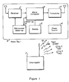
- FIG. 1 is a block diagram of the radio tag subsystem of apparatus in accordance with the present invention.
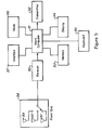
- Figure 2 shows the use of multiple interrogators in a cellular tag tracking system, in accordance with the present invention.
- FIG 3 is a block diagram of the MESFET front end of the tag receiver shown in Figure 1.
- Figure 4 is a schematic diagram of the micropower wake-up circuit shown in Figure 1.
- FIG. 5 is a block diagram of interrogator subsystem of apparatus in accordance with the present invention.
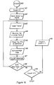
- FIG. 6 is a flowchart of the Batch Collection Protocol as implemented in the interrogator subsystem of Figure 5.
- FIG. 7 is a flowchart of the Batch Collection Protocol as implemented in the radio tag subsystem of Figure 1.
- Figure 8 is a timing diagram showing the operation of the random delay process.
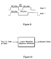
- FIG. 9 is description of the preferred data format for communications between the tag and interrogation subsystems in accordance with the present invention.
- Figure 10 is a functional block diagram of one embodiment of a linear recursive sequence generator in accordance with the present invention.
- the tag transceiver subsystem 8 is comprised of a receiver 1 to capture and demodulate the signal 10 from the interrogator 7 and a transmitter 3 to modulate and emit the signal 99 back to the interrogator 7. Further comprising this tag are a microcomputer 2, which processes data from the received signal, applies batch collection protocol to verify communications and controls the transmitter 3; a power source 6; an optional display 5; and a micropower wake-up circuit 4.
- the wake-up circuit 4 keeps the tag in a very low power state until a predefined wake-up signal is heard.
- the display 5 can be used to provide status information about the identification or tracking process, or to display other messages to personnel viewing the RF tag 1.
- interrogators 10 may be positioned and networked to create a cellular reception environment.
- Interrogators 10, 101, 102, 103 located in each of the cells 15, 12, 13, 14 communicate with a computer 11 via a network 110 of conventional design (wired-line, optical fiber, radio link, etc.), and also with all of the radio tags located within the communication cell of that interrogator.
- the cells 12, 13, 14, 15 correspond with the communication radius of the interrogators 101, 102, 103, 10, respectively.
- An array of these interrogator communication cells placed strategically around a facility provides the necessary communications structure to communicate with all of the tags located in the facility.
- the corresponding interrogator communicates the identification code to the monitoring computer, thereby identifying not only the tag, but the approximate location of the tag as well. If only identification information, and not location information, is required, a single cell system without a computer 11 or network 110 may be used, in accordance with the present invention.
- any type of receiver and transmitter can be used in accordance with the invention (e.g., infrared, acoustic, RF, optical, magnetic).
- RF at VHF is used.
- a receiver module 1 comprising a conventional superregenerative receiver 22 coupled to a MESFET front-end 21 and a conventional on/off keyed AM transmitter 3 are used.
- any type of microcomputer 2 can be used as long as the speed of the processor is sufficient to process the data and implement the necessary batch collection protocol.
- an 8-bit microcontroller is employed.
- the tag receiver 1 is a modified superregenerative receiver.
- the modification is shown in Figure 3 and involves the addition of an FET (field-effect transistor) front end 21 to a superregenerative receiver of the standard variety 22.
- FET field-effect transistor
- the superregenerative receiver would emit an RF signal (noise) back into the environment via the directly-connected antenna and would interfere with the reception capabilities of other close-proximity tags.
- FET circuits characteristically have extremely high reverse signal isolation, so the use of a FET front end substantially reduces leakage of RF and quench energy from the receiver and at the same time increases the sensitivity of the receiver.
- this design in accordance with the present invention permits the use of an inexpensive receiver design, such as a superregenerative circuit, in the demanding network environment of radio tag communications.
- the receiver module 1 in the tag subsystem 8 normally remains in a quiescent low-power state for all but a small fraction of the time. During the small time intervals that the receiver module 1 in the tag subsystem 8 is activated, the energizing power from the wake-up module 4 allows detection of the wakeup signal arriving from the interrogator 7. If no such signal is detected, the tag receiver subsystem 8 continues its sleep/wake cycle by returning to the low-power state. If, however, RF energy from the interrogator 7 is detected, the tag subsystem 8 changes to full power mode to prepare for communication with the interrogator 7.
- the micropower wake-up circuit 4 uses an extremely low-drain astable oscillator to strobe energy to the receiver.
- the design of the wake-up circuit 4 is based on a programmable opamp 30 used in an extremely-low power mode.
- a 50 megohm current-set resistor 31 is employed.
- High-speed switching diodes 32, 33 are configured in a quasi anti-parallel mode to provide a highly assymetric (low duty cycle) wakeup waveform.
- Resistors 37 and 38 are used to bias op-amp 30 at a level one half of the system voltage level.
- Resistor 34 and capacitor 35 are selected to provide an oscillator which is active for a short period (approximately 1 millisecond in the preferred embodiment) and inactive for a long period (approximately 1 second in the preferred embodiment).
- the oscillator signal then strobes a pair of high source-current logic gates 36, 37, which can then cleanly power the rest of the receiver circuit.
- the resulting power strobe circuit of Figure 4 has the ability to source the current (10 milliamps) necessary to power the receiver circuit, yet itself draws only 2 microamps on average during the 99 msec. that the receiver is not active.
- the interrogator apparatus consists of a receiver 50, a microcomputer 51, a transmitter 52, memory 53, and optionally a display 54, optional keypad 55, modem 56 and cable interface 57. All of these components are conventional in design except possibly for the receiver 50.
- the receiver 50 may be either of conventional superhetrodyne design or may be an FET-modified superregenerative receiver such as described in connection with Figure 3.
- Example techniques may be employed in accordance with the invention to improve the robustness of the communication against signal multipath and other interference.
- Example techniques include antenna diversity, frequency diversity, polarization diversity, and time diversity.
- a combination of antennas 59, 60, 61 employing both polarization diversity and spatial diversity are used in the front end module 58 to the receiver 50.
- a second mode of signal enhancement that may be employed in the interrogator apparatus is parameter enhancement. For instance, effective transmission power may be enhanced through the use of repeater apparatus, and other apparatus may be used to determine the direction and range from a repeater to a tag.
- certain relay units rebroadcast a tag signal to a more distant interrogator unit that has a particular association with that particular tag.
- the ranging and direction-finding enhancements may be implemented by employing acoustic transducers in one path of the two-way link between the tag and the interrogator. Acoustic waves propogate much more slowly than do electromagnetic waves and therefore can be used for more accurate short-range location using conventional echo-location techniques.
- multiple acoustic beams may be used to provide direction measurement using conventional triangulation techniques.
- a batch collection protocol or method is employed to handle situations in which multiple tag subsystems respond simultaneously to the presence of RF energy from an interrogation subsystem 7.
- a interrogation "wake-up" signal is transmitted by the interrogator 62.
- this signal is a VHF radio signal modulated at 62 KHz. This signal must be sent for a period equal to or greater than the micro-power scan period, or 1000 milliseconds in the preferred embodiment.
- the wake-up signal is received by the tag 1, the reset pin of the microcomputer 2 is activated. The reset wakes up the microcomputer from its low-power state and initiates the wake-up routine. The routine is called "Listen for Hello" 72.
- a "Hello” command is sent by the interrogator.
- the "Hello” is a signal that instructs all tags that have been awakened to begin their response protocol.
- the preferred format of the "Hello” signal, and all other data exhanges is a pulse-width modulated code which is configured with 80 microsecond pulses and 40 or 80 microsecond spaces, corresponding to a data information bandwidth not exceeding 25 kHz.
- other data exchange systems could also be used in accordance with the present invention.
- the reception of the "Hello" signal begins the send/acknowledge loop shown as steps 73, 74, 75 in Figure 7.
- a delay is computed 73. This delay needs to be as random as possible for the collision avoidance technique to work efficiently.
- a linear recursive sequence generator 90 seeded by the tag identification address is used to generate these delays, as shown in Figure 10.
- the tag responds at this delay time with its identification address 74 and then waits for acknowledgement 75.
- the interrogator places all of the identification codes heard during the cycle into a dynamic database 65.
- the listen cycle (assuming at least one ID code was heard) it transmits the list of received ID codes back to the tags 66. If no new tag signals were received 67, 68, 69 then the process ends.
- the tags collectively wait for acknowledgement that they were heard 75. If the unique ID code of a tag is properly received in the interrogator acknowledge cycle 66, 75 then this tag can return to stand by mode 76. If it is not acknowledged, then the tag tries again by sending its ID code back to the interrogator, albeit with a different delay period 72, 73, 74, 75.
- the probability of tag responses colliding on top of one another is small and gets even less probable as the process continues.
- the probability of collision of each cycle is determined by the duty cycle, the listen period, the number of tags heard and the degree of randomness of the transmit delay for each transmission.
- a probability of collision of one per one hundred tag units is defined.
- the collision iteration process occurs at approximately a square-law rate.
- the interrogator wakes-up all tags in the wake-up state 81, begins the listen cycle 82 by sending out a 'hello' command, acknowledges tags 83 and repeats the process 84, 85, 86 until all collisions have been resolved.
- the networking scheme described above can be further enhanced by the use of A) targeted wake-up [a special hello code is sent followed by an address code] which wakes up only that specific tag; B) messaging [the tag appends a message into its address in the listen cycle] and C) reverse messaging [the interrogator adds a message to a specific tag's acknowledgement].
- the collision avoidance method could employ randomization based on any of several communication parameters.
- response delay is used.
- the method could employ frequency, phase, amplitude or spatial variation as well.
- an identification and tracking system uses two-way communications between a central interrogator and individual radio transceiver tags to identify tagged items within the reception and transmission range of the interrogator.
Abstract
Description
- The present invention relates to an apparatus and to a method for identifying items through transmission and receiption of signals according to the preamble of
claims 1 and 8, respectively. (EP-A-161 779) - Generally, this invention relates to a method and apparatus for tracking and identifying physical objects, and more particularly to radio frequency identification and tracking systems using product tags having built-in radio frequency transceivers.
- A number of systems are known to exist that aid in the identification and tracking of physical objects in various environments. For instance, (1) Optical barcode readers are typically used in supermarkets to track product movement. (2) Optical character recognition systems are used in some department stores for the same purpose. (3) Magnetic stripe readers are commonly used to identify bank cards in automated teller machines. (4) Sophisticated security systems make use of voice recognition to identify humans. (5) Radio Frequency Identification ("RF/ID") offers another approach to automatic identification and tracking.
- Historically, RF/ID systems have used one of two radio communication techniques. One type of system has used passive RF reflectors, and the other type has used magnetic couplers.
- In the passive systems, RF-reflective "tags" are affixed to the products to be identified or tracked. When the products are positioned within sufficient range of an RF source, the tags are energized by the incident RF energy. The illuminated tags reflect a portion of the RF back to a receiver, modifying some aspect of the RF in the process. The product is identified by the manner in which the incident RF energy is modified upon reflection.
- The passive reflector tags of the prior art have several inherent limitations. The signal-to-noise ratio of the resultant identification signal is dependent upon the incident power level of the illuminating RF source, the geometry of the reflector and the efficiency of the modulation and reflection process. It is therefore common for the identification signal to be substantially weaker (e.g., 100 dB weaker) than the illuminating signal. Thus, very strong illuminating signals are required for the process to work even over limited ranges. Accordingly, passive reflector systems require directed illumination rather than omnidirectional illumination to achieve reasonable ranges. Omnidirectional illumination is generally preferred because it does not require prior knowledge of the location of the tag with respect to the illuminating source.
- Additionally, the communication process of a passive reflector is fundamentally one-way. The purpose of the illuminator is not to communicate any information to the tag, but only to provide a source of activating energy. There is no method for "handshaking" between the product tag and the central system to verify that the proper identification has been made.
- The third disadvantage of passive reflector tags of the prior art is their inability to dynamically store data. The interrogator of such a system has no means to dynamically write data into the tag for later re-transmission by the tag. Effectively, the tag becomes a mere static identifier for the attached item. Such tags lack the capability to change characteristics appropriate to the dynamic environment of the tags.
- In systems using magnetic coupling, radio tags are energized by movement through a magnetic field, and the energized tags transmit magnetically-coupled energy back to the interrogator unit. Am alternating field generated by an induction coil may be employed to generate the requisite energizing magnetic field for this system. This communication is typically transmitted at very low frequencies ("VLF").
- Magnetically-coupled radio tags are inherently restricted to close-range communications. This is due to the coupling inefficiency of small loop antennas (necessitated by the tag size) at VLF frequencies.
- The EP-A-161 779 discloses a method for identifying and tracking items, wherein a transceiver tag is associated to each of the items to be tracked, an interrogation signal is transmitted to the transceiver tags, identification signals are selectively transmitted from the transceiver tags, the identification signals are received, a verification signal is transmitted and, if the tag identifying signal is not followed immediately by a tag acknowledgment signal that is recognized by the tag, the tag continuous repeatedly to send a tag identifying signal. According to this document tags continuously transmit signals without any reference or correlation to what other tags are doing.
- The present invention provides an apparatus and a method for identifying items through transmission and receiption of signals, comprising the features of
claims 1 and 8, respectively. - To overcome the limitations of the prior art RF/ID systems, the method and apparatus of the present invention includes radio frequency reception and transmission capability at both the tag end and at the interrogation end of the system. Communication via active optical, infrared, UV, magnetic and acoustic media could also be used in accordance with the present invention. The method and apparatus of the present invention uses handshaking to verify the receipt of correct information from each individually tagged item. In accordance with the present invention, spatial, polarization, time and frequency diversity methods may be employed to overcome the limitations of multipath or multiple-device interference in the radio tag environment. The method and apparatus of the present invention use a intentional cellular communication range restriction to assist in the locating of said tags. In accordance with the present invention a MESFET front end is coupled to a super-regenerative receiver. This electronic circuit configuration substantially reduces interference normally associated with super-regenerative receivers and permits the use of inexpensive super-regenerative receiver technology in the congested environment of closely associated radio tags. In accordance with the present invention some characteristic of the intentional radiation (e.g., phase, time-of-arrival, angle-of-arrival) is used to determine the location of the tag relative to the interrogator within a cell. The method and apparatus of the present invention also increases the robustness of communications by handling situations in which signals from individual tags are time-coincident at the interrogation end.
- Figure 1 is a block diagram of the radio tag subsystem of apparatus in accordance with the present invention.
- Figure 2 shows the use of multiple interrogators in a cellular tag tracking system, in accordance with the present invention.
- Figure 3 is a block diagram of the MESFET front end of the tag receiver shown in Figure 1.
- Figure 4 is a schematic diagram of the micropower wake-up circuit shown in Figure 1.
- Figure 5 is a block diagram of interrogator subsystem of apparatus in accordance with the present invention.
- Figure 6 is a flowchart of the Batch Collection Protocol as implemented in the interrogator subsystem of Figure 5.
- Figure 7 is a flowchart of the Batch Collection Protocol as implemented in the radio tag subsystem of Figure 1.
- Figure 8 is a timing diagram showing the operation of the random delay process.
- Figure 9 is description of the preferred data format for communications between the tag and interrogation subsystems in accordance with the present invention.
- Figure 10 is a functional block diagram of one embodiment of a linear recursive sequence generator in accordance with the present invention.
- Referring now to Figure 1, a block diagram for apparatus in accordance with the present invention is shown. Two major types of subsystems comprise the apparatus: the
tag transceiver subsystems 8, 120, 130, 140 and the interrogator subsystem 7. The tag transceiver subsystem 8 is comprised of areceiver 1 to capture and demodulate the signal 10 from the interrogator 7 and atransmitter 3 to modulate and emit the signal 99 back to the interrogator 7. Further comprising this tag are amicrocomputer 2, which processes data from the received signal, applies batch collection protocol to verify communications and controls thetransmitter 3; a power source 6; an optional display 5; and a micropower wake-up circuit 4. The wake-up circuit 4 keeps the tag in a very low power state until a predefined wake-up signal is heard. The display 5 can be used to provide status information about the identification or tracking process, or to display other messages to personnel viewing theRF tag 1. - Referring now to Figure 2, multiple interrogators may be positioned and networked to create a cellular reception environment.
Interrogators cells computer 11 via anetwork 110 of conventional design (wired-line, optical fiber, radio link, etc.), and also with all of the radio tags located within the communication cell of that interrogator. Thecells interrogators computer 11 ornetwork 110 may be used, in accordance with the present invention. - Referring now to Figure 1 and Figure 3, any type of receiver and transmitter can be used in accordance with the invention (e.g., infrared, acoustic, RF, optical, magnetic). In the preferred embodiment RF at VHF is used. A
receiver module 1 comprising aconventional superregenerative receiver 22 coupled to a MESFET front-end 21 and a conventional on/off keyedAM transmitter 3 are used. Also, any type ofmicrocomputer 2 can be used as long as the speed of the processor is sufficient to process the data and implement the necessary batch collection protocol. In the preferred embodiment, an 8-bit microcontroller is employed. - In the preferred embodiment, the
tag receiver 1 is a modified superregenerative receiver. The modification is shown in Figure 3 and involves the addition of an FET (field-effect transistor) front end 21 to a superregenerative receiver of thestandard variety 22. Without the use of the FET front-end, the superregenerative receiver would emit an RF signal (noise) back into the environment via the directly-connected antenna and would interfere with the reception capabilities of other close-proximity tags. FET circuits characteristically have extremely high reverse signal isolation, so the use of a FET front end substantially reduces leakage of RF and quench energy from the receiver and at the same time increases the sensitivity of the receiver. As a result, this design in accordance with the present invention permits the use of an inexpensive receiver design, such as a superregenerative circuit, in the demanding network environment of radio tag communications. - Referring now to Figures 1 and 4, to increase the service life of the power source 6, which is typically a small battery, the
receiver module 1 in the tag subsystem 8 normally remains in a quiescent low-power state for all but a small fraction of the time. During the small time intervals that thereceiver module 1 in the tag subsystem 8 is activated, the energizing power from the wake-upmodule 4 allows detection of the wakeup signal arriving from the interrogator 7. If no such signal is detected, the tag receiver subsystem 8 continues its sleep/wake cycle by returning to the low-power state. If, however, RF energy from the interrogator 7 is detected, the tag subsystem 8 changes to full power mode to prepare for communication with the interrogator 7. - Referring now to Figure 1 and Figure 4, in the preferred embodiment, the micropower wake-
up circuit 4 uses an extremely low-drain astable oscillator to strobe energy to the receiver. The design of the wake-up circuit 4 is based on a programmable opamp 30 used in an extremely-low power mode. In the preferred embodiment, a 50 megohm current-setresistor 31 is employed. High-speed switching diodes Resistor 34 andcapacitor 35 are selected to provide an oscillator which is active for a short period (approximately 1 millisecond in the preferred embodiment) and inactive for a long period (approximately 1 second in the preferred embodiment). The oscillator signal then strobes a pair of high source-current logic gates 36, 37, which can then cleanly power the rest of the receiver circuit. - The resulting power strobe circuit of Figure 4 has the ability to source the current (10 milliamps) necessary to power the receiver circuit, yet itself draws only 2 microamps on average during the 99 msec. that the receiver is not active.
- Referring now to Figure 5, the interrogator apparatus consists of a receiver 50, a microcomputer 51, a transmitter 52, memory 53, and optionally a
display 54,optional keypad 55,modem 56 andcable interface 57. All of these components are conventional in design except possibly for the receiver 50. The receiver 50 may be either of conventional superhetrodyne design or may be an FET-modified superregenerative receiver such as described in connection with Figure 3. - Various techniques may be employed in accordance with the invention to improve the robustness of the communication against signal multipath and other interference. Example techniques include antenna diversity, frequency diversity, polarization diversity, and time diversity. In the preferred embodiment, a combination of
antennas front end module 58 to the receiver 50. - A second mode of signal enhancement that may be employed in the interrogator apparatus is parameter enhancement. For instance, effective transmission power may be enhanced through the use of repeater apparatus, and other apparatus may be used to determine the direction and range from a repeater to a tag. To implement the repeater enhancement, certain relay units rebroadcast a tag signal to a more distant interrogator unit that has a particular association with that particular tag. Such a system increases the effective range between tags and their associated interrogators. The ranging and direction-finding enhancements may be implemented by employing acoustic transducers in one path of the two-way link between the tag and the interrogator. Acoustic waves propogate much more slowly than do electromagnetic waves and therefore can be used for more accurate short-range location using conventional echo-location techniques. In addition, multiple acoustic beams may be used to provide direction measurement using conventional triangulation techniques.
- Referring now to Figures 6, 7 and 8, in accordance with the invention, a batch collection protocol or method is employed to handle situations in which multiple tag subsystems respond simultaneously to the presence of RF energy from an interrogation subsystem 7.
- Many common applications of the present invention would not require constant interrogation of all tags within radio range of the interrogator 7. In such applications, all tags normally remain in low-power standby mode, as previously discussed. When interrogation is desired, a interrogation "wake-up" signal is transmitted by the
interrogator 62. In the preferred embodiment this signal is a VHF radio signal modulated at 62 KHz. This signal must be sent for a period equal to or greater than the micro-power scan period, or 1000 milliseconds in the preferred embodiment. When the wake-up signal is received by thetag 1, the reset pin of themicrocomputer 2 is activated. The reset wakes up the microcomputer from its low-power state and initiates the wake-up routine. The routine is called "Listen for Hello" 72. - After a delay sufficient for all tags to get to
state 72, a "Hello" command is sent by the interrogator. The "Hello" is a signal that instructs all tags that have been awakened to begin their response protocol. Referring now to Figure 9, the preferred format of the "Hello" signal, and all other data exhanges, is a pulse-width modulated code which is configured with 80 microsecond pulses and 40 or 80 microsecond spaces, corresponding to a data information bandwidth not exceeding 25 kHz. However, other data exchange systems could also be used in accordance with the present invention. - The reception of the "Hello" signal begins the send/acknowledge loop shown as
steps - The tag responds at this delay time with its identification address 74 and then waits for
acknowledgement 75. During this fixed listen cycle 64, the interrogator places all of the identification codes heard during the cycle into a dynamic database 65. At the end of the listen cycle (assuming at least one ID code was heard) it transmits the list of received ID codes back to thetags 66. If no new tag signals were received 67, 68, 69 then the process ends. - The tags collectively wait for acknowledgement that they were heard 75. If the unique ID code of a tag is properly received in the interrogator acknowledge
cycle different delay period - Since the transmission time of the identification packet is small relative to the listen period (see Figure 7), the probability of tag responses colliding on top of one another is small and gets even less probable as the process continues. The probability of collision of each cycle is determined by the duty cycle, the listen period, the number of tags heard and the degree of randomness of the transmit delay for each transmission.
- For the preferred embodiment, a probability of collision of one per one hundred tag units is defined.
- Typically, with a well balanced collision protocol, the collision iteration process occurs at approximately a square-law rate.
- The timing of this process is demonstrated graphically in Figure 8. The interrogator wakes-up all tags in the wake-up state 81, begins the listen cycle 82 by sending out a 'hello' command, acknowledges tags 83 and repeats the process 84, 85, 86 until all collisions have been resolved.
- The networking scheme described above can be further enhanced by the use of A) targeted wake-up [a special hello code is sent followed by an address code] which wakes up only that specific tag; B) messaging [the tag appends a message into its address in the listen cycle] and C) reverse messaging [the interrogator adds a message to a specific tag's acknowledgement].
- In accordance with the present invention, the collision avoidance method could employ randomization based on any of several communication parameters. In the preferred embodiment, response delay is used. However, the method could employ frequency, phase, amplitude or spatial variation as well.
- Therefore, an identification and tracking system uses two-way communications between a central interrogator and individual radio transceiver tags to identify tagged items within the reception and transmission range of the interrogator.
Claims (12)
- Apparatus for identifying items through transmission and reception of signals comprising:a plurality of tag transceivers (8; 120, 130, 140), one for each of said items, each of said tag transceivers (8; 120, 130, 140) including signal receiving means (1; 21, 22) and sending means (3);an interrogation transceiver (7) for communicating with said tag transceivers, said interrogation transceiver (7) including signal sending means (52) and receiving means (50);wherein said tag transceivers and said interrogation transceiver communicate with a communication protocol, characterized in thatsaid communication protocol is a batch protocol including a sequence, common to all tag transceivers, havinga listen period during which each of said plurality of tag transceivers can communicate a tag identifying signal to said interrogation transceiver andan acknowledge period during which said interrogation transceiver can communicate acknowledge signals to said tag transceivers; and thatsaid signal sending means (52) of said interrogation transceiver are adapted for sending a start signal to the tag transceivers to signal the commencement of the listen period, said receiving means (50) of said interrogation transceiver are adapted to receive tag identifying signals during said listen period from a subset of said tag transceivers, and said signal sending means (52) of said interrogation transceiver are further adapted for sending acknowledge signals during said acknowledge period to said subset of said tag transceivers; andsaid signal receiving means (1; 21, 22) of said tag transceivers are adapted for receiving the start signal from the signal sending means (52) of said interrogation transceiver so as to identify the start of the listen period, said sending means (3) of said tag transceivers are adapted for sending a tag identifying signal during the listen period, and said signal receiving means (1; 21, 22) of said tag transceivers are adapted for receiving an acknowledge signal from said interrogation transceiver during the acknowledged period.
- Apparatus as in claim 1, characterized in that the tag transceivers (8,120,130,140) remain in a low-power standby mode until activated by said start signal (81) from the interrogation transceiver (7).
- Apparatus as in claims 1 or 2, characterized in that the tag identifying signal from each tag transceiver (8,120,130,140) is unique.
- Apparatus as in one of the preceding claims, characterized in that a power strobe circuit periodically provides a signal to a microprocessor in each tag transceiver to cause low-power standby operation.
- Apparatus as in one of the preceding claims, characterized in that the tag transceivers (8,120,130,140) comprise means (2) for delaying the transmission of the tag identifying signal by any remaining tag transceivers for a particular period of time after the interrogation transceiver signals that retransmission will be required.
- Apparatus as in claim 5, characterized in that the particular period of time is different for each remaining tag transceiver and is determined in a pseudorandom manner.
- Apparatus as in one of the preceding claims, further characterized in that the apparatus comprises means for determining the location of tag transceivers tags (8,120,130,140).
- Method for identifying items through transmission and reception of signals in a system comprising:a plurality of tag transceivers (8; 120, 130, 140), one for each of said items,an interrogation transceiver (7) for communicating with said tag transceivers,wherein said tag transceivers and said interrogation transceiver communicate with a communication protocol, characterized in thatsaid communication protocol is a batch protocol including a sequence, havinga listen period during which each of said plurality of tag transceivers can communicate a tag identifying signal to said interrogation transceiver and having an acknowledge period during which said interrogation transceiver can communicate acknowledge signals to said tag transceivers; and thatsaid interrogation transceiver sends a start signal to the tag transceivers to signal the commencement of the listen period, receives tag identifying signals during said listen period from a subset of said tag transceivers, and sends acknowledge signals during said acknowledge period to said subset of said tag transceivers; and thatsaid tag transceivers receives the start signal from said interrogation transceiver so as to identify the start of the listen period, sends a tag identifying signal during the listen period, and receives an acknowledge signal from said interrogation transceiver during the acknowledged period.
- The method according to claim 8, characterized in that the start signal and the acknowledge signals are transmitted by a central interrogation transceiver subsystem.
- The method according to claims 8 or 9, characterized in that all tag transceivers within a receiving range of the start signal transmit identification signals.
- The method according to claims 8, 9 or 10, characterized in that the step of transmitting tag identifying signals further comprises the step of each tag transceiver delaying the initiation of transmission of the tag identifying signal a particular amount of time after receipt of the start signal.
- The method as in claim 11, characterized in that the particular amount of time is determined in a pseudorandom manner.
Applications Claiming Priority (2)
| Application Number | Priority Date | Filing Date | Title |
|---|---|---|---|
| US53854690A | 1990-06-15 | 1990-06-15 | |
| US538546 | 1990-06-15 |
Publications (3)
| Publication Number | Publication Date |
|---|---|
| EP0467036A2 EP0467036A2 (en) | 1992-01-22 |
| EP0467036A3 EP0467036A3 (en) | 1992-04-22 |
| EP0467036B1 true EP0467036B1 (en) | 1996-02-07 |
Family
ID=24147358
Family Applications (1)
| Application Number | Title | Priority Date | Filing Date |
|---|---|---|---|
| EP91107878A Expired - Lifetime EP0467036B1 (en) | 1990-06-15 | 1991-05-15 | Method and apparatus for radio identification and tracking |
Country Status (7)
| Country | Link |
|---|---|
| EP (1) | EP0467036B1 (en) |
| JP (1) | JPH04232488A (en) |
| AT (1) | ATE134044T1 (en) |
| DE (1) | DE69116946T2 (en) |
| DK (1) | DK0467036T3 (en) |
| ES (1) | ES2082885T3 (en) |
| GR (1) | GR3019842T3 (en) |
Cited By (20)
| Publication number | Priority date | Publication date | Assignee | Title |
|---|---|---|---|---|
| DE112005000319T5 (en) | 2004-02-06 | 2008-07-03 | Zih Corp. | Selection and arbitration method and system |
| US7639118B2 (en) | 1998-11-07 | 2009-12-29 | Ian J Forster | Receiver circuit |
| US7800503B2 (en) | 2006-05-11 | 2010-09-21 | Axcess International Inc. | Radio frequency identification (RFID) tag antenna design |
| US7841120B2 (en) | 2004-03-22 | 2010-11-30 | Wilcox Industries Corp. | Hand grip apparatus for firearm |
| US7928843B2 (en) | 2001-02-12 | 2011-04-19 | Symbol Technologies, Inc. | Method, system, and apparatus for communications in a RFID system |
| CN101467157B (en) * | 2006-06-13 | 2011-09-28 | Nxp股份有限公司 | Method, RFID reader, RFID tag and RFID system for secure communication |
| US8068807B2 (en) | 2000-12-22 | 2011-11-29 | Terahop Networks, Inc. | System for supplying container security |
| US8078139B2 (en) | 2000-12-22 | 2011-12-13 | Terahop Networks, Inc. | Wireless data communications network system for tracking container |
| US8207848B2 (en) | 2008-05-16 | 2012-06-26 | Google Inc. | Locking system for shipping container including bolt seal and electronic device with arms for receiving bolt seal |
| US8223680B2 (en) | 2007-02-21 | 2012-07-17 | Google Inc. | Mesh network control using common designation wake-up |
| US8279067B2 (en) | 2008-05-16 | 2012-10-02 | Google Inc. | Securing, monitoring and tracking shipping containers |
| US8280345B2 (en) | 2000-12-22 | 2012-10-02 | Google Inc. | LPRF device wake up using wireless tag |
| US8284741B2 (en) | 2000-12-22 | 2012-10-09 | Google Inc. | Communications and systems utilizing common designation networking |
| US8300551B2 (en) | 2009-01-28 | 2012-10-30 | Google Inc. | Ascertaining presence in wireless networks |
| US8315565B2 (en) | 2000-12-22 | 2012-11-20 | Google Inc. | LPRF device wake up using wireless tag |
| US8325016B2 (en) | 2000-02-28 | 2012-12-04 | Magellan Technology Pty Limited | Radio frequency identification transponder |
| US8638194B2 (en) | 2008-07-25 | 2014-01-28 | Axcess International, Inc. | Multiple radio frequency identification (RFID) tag wireless wide area network (WWAN) protocol |
| US8705523B2 (en) | 2009-02-05 | 2014-04-22 | Google Inc. | Conjoined class-based networking |
| US9083580B2 (en) | 2008-07-02 | 2015-07-14 | Frank Schmidt | Receiver device, system, and method for low-energy reception of data |
| US9532310B2 (en) | 2008-12-25 | 2016-12-27 | Google Inc. | Receiver state estimation in a duty cycled radio |
Families Citing this family (112)
| Publication number | Priority date | Publication date | Assignee | Title |
|---|---|---|---|---|
| JP3100716B2 (en) * | 1991-01-04 | 2000-10-23 | シーエスアイアール | Identification device |
| GB2259227B (en) * | 1991-08-30 | 1995-10-18 | Marconi Gec Ltd | Improvements in or relating to transponders |
| EP0623219B1 (en) * | 1992-01-23 | 1999-03-24 | Saab-Scania Combitech Aktiebolag | Device for wireless transfer of information |
| SE9201864D0 (en) * | 1992-06-17 | 1992-06-17 | Saab Scania Combitech Ab | SYSTEM FOR INFORMATION TRANSFER WITH MULTIPLE TRANSPONDERS |
| JPH05273338A (en) * | 1992-03-27 | 1993-10-22 | Sharp Corp | Traveling object identifying device |
| SE470241B (en) | 1992-05-11 | 1993-12-13 | Tony Westman | Transponder system for locating an object |
| CA2103288C (en) * | 1992-11-18 | 2004-08-17 | Michael John Camille Marsh | Detection of multiple articles |
| US5790946A (en) | 1993-07-15 | 1998-08-04 | Rotzoll; Robert R. | Wake up device for a communications system |
| US5530702A (en) * | 1994-05-31 | 1996-06-25 | Ludwig Kipp | System for storage and communication of information |
| US5550547A (en) * | 1994-09-12 | 1996-08-27 | International Business Machines Corporation | Multiple item radio frequency tag identification protocol |
| IT1279591B1 (en) * | 1995-05-12 | 1997-12-16 | Marposs Spa | SYSTEM AND METHOD OF TRANSMISSION OF SIGNALS OVER ETHER FOR CONTROL PROBES |
| FR2734381B1 (en) * | 1995-05-17 | 1997-07-04 | Applic Electroniques Et De Tel | REMOTE COMMUNICATION DEVICE AND METHOD FOR TRACKING MOVING PRODUCTS |
| DE19526353A1 (en) * | 1995-07-19 | 1997-01-23 | Anatoli Stobbe | Process for the automatic identification of an unknown number of transponders by a reader and identification system for carrying out the process |
| GB2309132B (en) * | 1996-01-11 | 2000-09-20 | Hugh Malcolm Ian Bell | Object location system |
| US6812824B1 (en) | 1996-10-17 | 2004-11-02 | Rf Technologies, Inc. | Method and apparatus combining a tracking system and a wireless communication system |
| CA2268951A1 (en) | 1996-10-17 | 1998-04-23 | Pinpoint Corporation | Article tracking system |
| GB2319698B (en) * | 1996-11-21 | 2001-08-08 | Motorola Inc | Method for communicating with a plurality of contactless data carriers and contactless data carrier for use therein |
| DE19652227A1 (en) | 1996-12-16 | 1998-06-18 | Bosch Gmbh Robert | Method and device for assigning a remote control to a base station |
| US6104333A (en) * | 1996-12-19 | 2000-08-15 | Micron Technology, Inc. | Methods of processing wireless communication, methods of processing radio frequency communication, and related systems |
| US6034603A (en) * | 1997-01-24 | 2000-03-07 | Axcess, Inc. | Radio tag system and method with improved tag interference avoidance |
| US6570487B1 (en) | 1997-01-24 | 2003-05-27 | Axcess Inc. | Distributed tag reader system and method |
| FR2759190B1 (en) * | 1997-02-04 | 1999-04-23 | Francois Legrain | SYSTEM FOR THE INDIVIDUAL IDENTIFICATION OF ANIMALS OR OBJECTS HOLDING A BADGE |
| US5883582A (en) * | 1997-02-07 | 1999-03-16 | Checkpoint Systems, Inc. | Anticollision protocol for reading multiple RFID tags |
| GB2323252A (en) * | 1997-03-11 | 1998-09-16 | Nicholas John Nelson | Radio frequency tagging of stock items |
| GB2325141A (en) | 1997-05-14 | 1998-11-18 | British Tech Group | Automatic milking system |
| BR9808714A (en) | 1997-05-14 | 2000-07-11 | Btg Int Ltd | Enhanced identification system |
| EP1662423A3 (en) * | 1997-08-28 | 2006-08-02 | Supersensor (Proprietary) Limited | Reader arrangement for an electronic identification system |
| CN1161709C (en) | 1997-09-26 | 2004-08-11 | 数据投资有限公司 | Delayed reset mode model for electronic identification systems |
| GB9724183D0 (en) * | 1997-11-14 | 1998-01-14 | British Tech Group | Identification system |
| US7035818B1 (en) | 1997-11-21 | 2006-04-25 | Symbol Technologies, Inc. | System and method for electronic inventory |
| US7844505B1 (en) | 1997-11-21 | 2010-11-30 | Symbol Technologies, Inc. | Automated real-time distributed tag reader network |
| EP0924635A3 (en) * | 1997-12-15 | 2001-01-10 | Data Investments Limited | Electronic indentification system including a reader and a plurality of transponders |
| GB2333623B (en) * | 1998-01-24 | 2000-04-26 | Plessey Telecomm | Transaction system |
| US6252886B1 (en) | 1998-07-06 | 2001-06-26 | Sony Corporation | Bandwidth reservation |
| JP2002520903A (en) * | 1998-07-06 | 2002-07-09 | ソニー株式会社 | How to secure bandwidth |
| US6177861B1 (en) * | 1998-07-17 | 2001-01-23 | Lucent Technologies, Inc | System for short range wireless data communication to inexpensive endpoints |
| US6480143B1 (en) * | 1998-11-09 | 2002-11-12 | Supersensor (Proprietary) Limited | Electronic identification system |
| US6535109B1 (en) * | 1998-12-01 | 2003-03-18 | Texas Instruments Sensors And Controls, Inc. | System and method for communicating with multiple transponders |
| US6294953B1 (en) | 1999-02-26 | 2001-09-25 | Axcess, Inc. | High sensitivity demodulator for a radio tag and method |
| JP2003500975A (en) * | 1999-05-21 | 2003-01-07 | ケーナー,ラルフ・ジェイ | Identification system for monitoring the presence / absence of members of a defined set |
| EP1734461A2 (en) | 1999-07-12 | 2006-12-20 | Matsushita Electric Industrial Co., Ltd. | Mobile body discrimination apparatus for rapidly acquiring respective data sets transmitted through modulation of reflected radio waves by transponders which are within a communication region of an interrogator apparatus |
| US7005985B1 (en) | 1999-07-20 | 2006-02-28 | Axcess, Inc. | Radio frequency identification system and method |
| US7286158B1 (en) | 1999-12-22 | 2007-10-23 | Axcess International Inc. | Method and system for providing integrated remote monitoring services |
| US6377203B1 (en) | 2000-02-01 | 2002-04-23 | 3M Innovative Properties Company | Collision arbitration method and apparatus for reading multiple radio frequency identification tags |
| US7248145B2 (en) | 2000-02-28 | 2007-07-24 | Magellan Technology Oty Limited | Radio frequency identification transponder |
| US7768546B1 (en) | 2000-05-12 | 2010-08-03 | Axcess International, Inc. | Integrated security system and method |
| US6329944B1 (en) | 2000-05-12 | 2001-12-11 | Northrop Grumman Corporation | Tag communication protocol & system |
| GB0015211D0 (en) * | 2000-06-21 | 2000-08-09 | Bath Med Eng Inst | Electronic device |
| CN1214338C (en) * | 2000-07-31 | 2005-08-10 | 皇家菲利浦电子有限公司 | Communication system and data carrier with improved acknowledgement measures |
| US6765484B2 (en) | 2000-09-07 | 2004-07-20 | Savi Technology, Inc. | Method and apparatus for supplying commands to a tag |
| US6720888B2 (en) | 2000-09-07 | 2004-04-13 | Savi Technology, Inc. | Method and apparatus for tracking mobile devices using tags |
| US6940392B2 (en) | 2001-04-24 | 2005-09-06 | Savi Technology, Inc. | Method and apparatus for varying signals transmitted by a tag |
| US7705747B2 (en) | 2005-08-18 | 2010-04-27 | Terahop Networks, Inc. | Sensor networks for monitoring pipelines and power lines |
| US7783246B2 (en) | 2005-06-16 | 2010-08-24 | Terahop Networks, Inc. | Tactical GPS denial and denial detection system |
| US7830273B2 (en) | 2005-08-18 | 2010-11-09 | Terahop Networks, Inc. | Sensor networks for pipeline monitoring |
| US7907941B2 (en) | 2006-01-01 | 2011-03-15 | Terahop Networks, Inc. | Determining presence of radio frequency communication device |
| US7742772B2 (en) | 2005-10-31 | 2010-06-22 | Terahop Networks, Inc. | Determining relative elevation using GPS and ranging |
| US6747558B1 (en) * | 2001-11-09 | 2004-06-08 | Savi Technology, Inc. | Method and apparatus for providing container security with a tag |
| EP1316814A1 (en) | 2001-11-30 | 2003-06-04 | Cross Point RFAPP B.V. i.o. | Tracing of transponder-tagged objects |
| DE10158615A1 (en) * | 2001-11-29 | 2003-07-03 | Siemens Ag | activation unit |
| US7009496B2 (en) | 2002-04-01 | 2006-03-07 | Symbol Technologies, Inc. | Method and system for optimizing an interrogation of a tag population |
| GB0213724D0 (en) * | 2002-06-14 | 2002-07-24 | Turner Christopher G G | Electronic identification system |
| EP1372103A1 (en) * | 2002-06-14 | 2003-12-17 | Christopher Gordon Gervase Turner | Electronic identification system |
| AU2003242885A1 (en) | 2002-06-26 | 2004-01-19 | Nokia Corporation | Device for directing the operation of a user's personal communication apparatus |
| FR2851836B1 (en) * | 2003-02-27 | 2006-03-03 | France Telecom | METHOD AND SYSTEM FOR IDENTIFYING AN OBJECT BELOW A LIST OF OBJECTS AND INFORMATION RECORDING MEDIA FOR PERFORMING THE METHOD. |
| US7259669B2 (en) | 2003-04-18 | 2007-08-21 | Savi Technology, Inc. | Method and apparatus for detecting unauthorized intrusion into a container |
| KR101297503B1 (en) | 2003-10-27 | 2013-08-16 | 사비 테크날러지 인코퍼레이티드 | Container security and monitoring |
| US7317387B1 (en) | 2003-11-07 | 2008-01-08 | Savi Technology, Inc. | Method and apparatus for increased container security |
| JP4795970B2 (en) | 2003-12-18 | 2011-10-19 | アルティエレ・コーポレーション | Low power wireless display tag system and method |
| SE0400556D0 (en) * | 2004-03-05 | 2004-03-05 | Pricer Ab | Electronic shelf labeling system, electronic label, handheld device and method in an electronic labeling system |
| EP1510960A1 (en) * | 2004-03-23 | 2005-03-02 | Siemens Transit Telematic Systems AG | Anticollision method in a contactless interrogation system |
| US7142107B2 (en) | 2004-05-27 | 2006-11-28 | Lawrence Kates | Wireless sensor unit |
| US8258950B2 (en) | 2004-07-15 | 2012-09-04 | Savi Technology, Inc. | Method and apparatus for control or monitoring of a container |
| US7362212B2 (en) | 2004-09-24 | 2008-04-22 | Battelle Memorial Institute | Communication methods, systems, apparatus, and devices involving RF tag registration |
| WO2006109700A1 (en) * | 2005-04-07 | 2006-10-19 | Nec Corporation | Rfid system, reader, control program and transmission method |
| WO2007100343A1 (en) | 2005-06-03 | 2007-09-07 | Terahop Networks Inc. | Remote sensor interface (rsi) stepped wake-up sequence |
| EP1905200A1 (en) | 2005-07-01 | 2008-04-02 | Terahop Networks, Inc. | Nondeterministic and deterministic network routing |
| JP4514676B2 (en) * | 2005-08-31 | 2010-07-28 | 富士通株式会社 | Information access system |
| US7538672B2 (en) | 2005-11-01 | 2009-05-26 | Savi Technology, Inc. | Method and apparatus for capacitive sensing of door position |
| US7808383B2 (en) | 2005-11-03 | 2010-10-05 | Savi Technology, Inc. | Method and apparatus for monitoring an environmental condition with a tag |
| US9285471B2 (en) * | 2005-11-21 | 2016-03-15 | Hewlett-Packard Development Company, L.P. | Method and apparatus for localization of RFID tags |
| US9813867B2 (en) | 2005-12-15 | 2017-11-07 | Polte Corporation | Angle of arrival (AOA) positioning method and system for positional finding and tracking objects using reduced attenuation RF technology |
| US7969311B2 (en) | 2005-12-15 | 2011-06-28 | Invisitrack, Inc. | Multi-path mitigation in rangefinding and tracking objects using reduced attenuation RF technology |
| US10091616B2 (en) | 2005-12-15 | 2018-10-02 | Polte Corporation | Angle of arrival (AOA) positioning method and system for positional finding and tracking objects using reduced attenuation RF technology |
| US10281557B2 (en) | 2005-12-15 | 2019-05-07 | Polte Corporation | Partially synchronized multilateration/trilateration method and system for positional finding using RF |
| US7561048B2 (en) * | 2005-12-15 | 2009-07-14 | Invisitrack, Inc. | Methods and system for reduced attenuation in tracking objects using RF technology |
| US9288623B2 (en) | 2005-12-15 | 2016-03-15 | Invisitrack, Inc. | Multi-path mitigation in rangefinding and tracking objects using reduced attenuation RF technology |
| US9913244B2 (en) | 2005-12-15 | 2018-03-06 | Polte Corporation | Partially synchronized multilateration or trilateration method and system for positional finding using RF |
| US9699607B2 (en) | 2005-12-15 | 2017-07-04 | Polte Corporation | Multi-path mitigation in rangefinding and tracking objects using reduced attenuation RF technology |
| US10834531B2 (en) | 2005-12-15 | 2020-11-10 | Polte Corporation | Multi-path mitigation in rangefinding and tracking objects using reduced attenuation RF technology |
| US7872583B1 (en) * | 2005-12-15 | 2011-01-18 | Invisitrack, Inc. | Methods and system for multi-path mitigation in tracking objects using reduced attenuation RF technology |
| US20090129306A1 (en) | 2007-02-21 | 2009-05-21 | Terahop Networks, Inc. | Wake-up broadcast including network information in common designation ad hoc wireless networking |
| US7667597B2 (en) | 2007-03-09 | 2010-02-23 | Savi Technology, Inc. | Method and apparatus using magnetic flux for container security |
| JP5134020B2 (en) * | 2007-03-23 | 2013-01-30 | モジクス, インコーポレイティッド | RFID system using distributed exciter network |
| JP5088606B2 (en) * | 2007-03-27 | 2012-12-05 | セイコーエプソン株式会社 | Wireless communication system |
| US8258927B1 (en) | 2007-04-06 | 2012-09-04 | Eigent Technologies, Inc. | Method and system for inventorying wireless transponders providing anti-eavesdropping anti-collision |
| KR100958239B1 (en) * | 2008-03-10 | 2010-05-17 | 엘에스산전 주식회사 | Rfid tag |
| US8427282B2 (en) | 2008-07-15 | 2013-04-23 | Zih Corp. | Identification system |
| AU2009273748A1 (en) | 2008-07-21 | 2010-01-28 | Sato Holdings Corporation | A device having data storage |
| EP2367021A1 (en) * | 2010-03-17 | 2011-09-21 | The Swatch Group Research and Development Ltd. | Method and system for locating objects |
| EP2509027B1 (en) | 2011-04-04 | 2019-02-06 | Nxp B.V. | Method for handling collision in an identification system |
| JP6166260B2 (en) | 2011-08-03 | 2017-07-19 | ポルテ・コーポレイションPoLTE Corporation | Multipath mitigation in object ranging and tracking using RF techniques with reduced attenuation |
| US11835639B2 (en) | 2011-08-03 | 2023-12-05 | Qualcomm Technologies, Inc. | Partially synchronized multilateration or trilateration method and system for positional finding using RF |
| US11125850B2 (en) | 2011-08-03 | 2021-09-21 | Polte Corporation | Systems and methods for determining a timing offset of emitter antennas in a wireless network |
| US10845453B2 (en) | 2012-08-03 | 2020-11-24 | Polte Corporation | Network architecture and methods for location services |
| US10863313B2 (en) | 2014-08-01 | 2020-12-08 | Polte Corporation | Network architecture and methods for location services |
| US10440512B2 (en) | 2012-08-03 | 2019-10-08 | Polte Corporation | Angle of arrival (AOA) positioning method and system for positional finding and tracking objects using reduced attenuation RF technology |
| US9112790B2 (en) | 2013-06-25 | 2015-08-18 | Google Inc. | Fabric network |
| WO2015198753A1 (en) * | 2014-06-26 | 2015-12-30 | 古野電気株式会社 | Signal processing device, transponder device, radar device, and signal processing method |
| JP6881157B2 (en) * | 2017-08-24 | 2021-06-02 | 日本製鉄株式会社 | Monitoring system, monitoring device, information processing method and program |
| US11255945B2 (en) | 2018-03-27 | 2022-02-22 | Polte Corporation | Multi-path mitigation in tracking objects using compressed RF data |
| TWI755138B (en) * | 2020-11-02 | 2022-02-11 | 凌通科技股份有限公司 | Radio frequency identification communication method for collision reduction with low power consumption and radio frequency identification communication system using the same |
Family Cites Families (5)
| Publication number | Priority date | Publication date | Assignee | Title |
|---|---|---|---|---|
| US4177466A (en) * | 1977-11-16 | 1979-12-04 | Lo-Jack Corporation | Auto theft detection system |
| GB8408538D0 (en) * | 1984-04-03 | 1984-05-16 | Senelco Ltd | Transmitter-responder systems |
| US4818998A (en) * | 1986-03-31 | 1989-04-04 | Lo-Jack Corporation | Method of and system and apparatus for locating and/or tracking stolen or missing vehicles and the like |
| DE3716320A1 (en) * | 1987-05-15 | 1988-11-24 | Bosch Gmbh Robert | METHOD FOR DETERMINING THE APPROXIMATE LOCATION OF A MOBILE RADIO STATION |
| GB2207787B (en) * | 1987-08-06 | 1991-10-30 | James Terence Barker | Retrieval of lost road vehicles and other articles |
-
1991
- 1991-05-15 DE DE69116946T patent/DE69116946T2/en not_active Expired - Lifetime
- 1991-05-15 ES ES91107878T patent/ES2082885T3/en not_active Expired - Lifetime
- 1991-05-15 DK DK91107878.0T patent/DK0467036T3/en active
- 1991-05-15 EP EP91107878A patent/EP0467036B1/en not_active Expired - Lifetime
- 1991-05-15 AT AT91107878T patent/ATE134044T1/en not_active IP Right Cessation
- 1991-06-14 JP JP3143178A patent/JPH04232488A/en active Pending
-
1996
- 1996-05-07 GR GR960401217T patent/GR3019842T3/en unknown
Cited By (24)
| Publication number | Priority date | Publication date | Assignee | Title |
|---|---|---|---|---|
| US7639118B2 (en) | 1998-11-07 | 2009-12-29 | Ian J Forster | Receiver circuit |
| US8325016B2 (en) | 2000-02-28 | 2012-12-04 | Magellan Technology Pty Limited | Radio frequency identification transponder |
| US8078139B2 (en) | 2000-12-22 | 2011-12-13 | Terahop Networks, Inc. | Wireless data communications network system for tracking container |
| US8315565B2 (en) | 2000-12-22 | 2012-11-20 | Google Inc. | LPRF device wake up using wireless tag |
| US8284741B2 (en) | 2000-12-22 | 2012-10-09 | Google Inc. | Communications and systems utilizing common designation networking |
| US8280345B2 (en) | 2000-12-22 | 2012-10-02 | Google Inc. | LPRF device wake up using wireless tag |
| US8238826B2 (en) | 2000-12-22 | 2012-08-07 | Google Inc. | Method for supplying container security |
| US8068807B2 (en) | 2000-12-22 | 2011-11-29 | Terahop Networks, Inc. | System for supplying container security |
| US7928843B2 (en) | 2001-02-12 | 2011-04-19 | Symbol Technologies, Inc. | Method, system, and apparatus for communications in a RFID system |
| US7965189B2 (en) | 2001-02-12 | 2011-06-21 | Symbol Technologies, Inc. | Radio frequency identification architecture |
| DE112005000319B4 (en) | 2004-02-06 | 2023-03-30 | Zebra Technologies Corporation | Selection and Arbitration Procedure and System |
| DE112005000319T5 (en) | 2004-02-06 | 2008-07-03 | Zih Corp. | Selection and arbitration method and system |
| US8981909B2 (en) | 2004-02-06 | 2015-03-17 | Zih Corp. | RFID group selection method |
| US7841120B2 (en) | 2004-03-22 | 2010-11-30 | Wilcox Industries Corp. | Hand grip apparatus for firearm |
| US7800503B2 (en) | 2006-05-11 | 2010-09-21 | Axcess International Inc. | Radio frequency identification (RFID) tag antenna design |
| CN101467157B (en) * | 2006-06-13 | 2011-09-28 | Nxp股份有限公司 | Method, RFID reader, RFID tag and RFID system for secure communication |
| US8223680B2 (en) | 2007-02-21 | 2012-07-17 | Google Inc. | Mesh network control using common designation wake-up |
| US8279067B2 (en) | 2008-05-16 | 2012-10-02 | Google Inc. | Securing, monitoring and tracking shipping containers |
| US8207848B2 (en) | 2008-05-16 | 2012-06-26 | Google Inc. | Locking system for shipping container including bolt seal and electronic device with arms for receiving bolt seal |
| US9083580B2 (en) | 2008-07-02 | 2015-07-14 | Frank Schmidt | Receiver device, system, and method for low-energy reception of data |
| US8638194B2 (en) | 2008-07-25 | 2014-01-28 | Axcess International, Inc. | Multiple radio frequency identification (RFID) tag wireless wide area network (WWAN) protocol |
| US9532310B2 (en) | 2008-12-25 | 2016-12-27 | Google Inc. | Receiver state estimation in a duty cycled radio |
| US8300551B2 (en) | 2009-01-28 | 2012-10-30 | Google Inc. | Ascertaining presence in wireless networks |
| US8705523B2 (en) | 2009-02-05 | 2014-04-22 | Google Inc. | Conjoined class-based networking |
Also Published As
| Publication number | Publication date |
|---|---|
| JPH04232488A (en) | 1992-08-20 |
| EP0467036A2 (en) | 1992-01-22 |
| DE69116946T2 (en) | 1996-06-20 |
| DE69116946D1 (en) | 1996-03-21 |
| ATE134044T1 (en) | 1996-02-15 |
| DK0467036T3 (en) | 1996-03-11 |
| ES2082885T3 (en) | 1996-04-01 |
| GR3019842T3 (en) | 1996-08-31 |
| EP0467036A3 (en) | 1992-04-22 |
Similar Documents
| Publication | Publication Date | Title |
|---|---|---|
| EP0467036B1 (en) | Method and apparatus for radio identification and tracking | |
| US6456191B1 (en) | Tag system with anti-collision features | |
| US5528232A (en) | Method and apparatus for locating items | |
| US6034603A (en) | Radio tag system and method with improved tag interference avoidance | |
| US5686902A (en) | Communication system for communicating with tags | |
| US7023356B2 (en) | System and method for monitoring individuals and objects associated with wireless identification tags | |
| EP1017005B1 (en) | A system and method for communicating with multiple transponders | |
| EP0789254B1 (en) | Detection of multiple articles | |
| US5751223A (en) | Electronic identification system | |
| CA2079112C (en) | Locating system | |
| US6538563B1 (en) | RF transponder identification system and protocol | |
| US6127928A (en) | Method and apparatus for locating and tracking documents and other objects | |
| US6726099B2 (en) | RFID tag having multiple transceivers | |
| US7295115B2 (en) | Radio-frequency identification (RFID) tag employing unique reception window and method therefor | |
| US6104279A (en) | Method of communication between a plurality of remote units and a control unit | |
| DE69923645D1 (en) | Electronic identification system | |
| EP1342382B1 (en) | Method for reading multiple transponders in an rfid system | |
| US20060220791A1 (en) | Method and system for RF activation of RF interrogators | |
| CA2299053C (en) | A method of detecting objects within range of a receiver | |
| EP1946147B1 (en) | Short-distance ranging system | |
| JP4478648B2 (en) | Method and apparatus for long distance reading of passive tags in a radio frequency identification system | |
| CA2266337C (en) | Tag system with anti-collision features | |
| WO2000046771A1 (en) | Technique for filtering signals in a local positioning system | |
| WO2001065481A1 (en) | Radio tag system and method with tag interference avoidance | |
| JPH04208890A (en) | Communication method for moving body recognizer |
Legal Events
| Date | Code | Title | Description |
|---|---|---|---|
| PUAI | Public reference made under article 153(3) epc to a published international application that has entered the european phase |
Free format text: ORIGINAL CODE: 0009012 |
|
| AK | Designated contracting states |
Kind code of ref document: A2 Designated state(s): AT BE CH DE DK ES FR GB GR IT LI LU NL SE |
|
| PUAL | Search report despatched |
Free format text: ORIGINAL CODE: 0009013 |
|
| AK | Designated contracting states |
Kind code of ref document: A3 Designated state(s): AT BE CH DE DK ES FR GB GR IT LI LU NL SE |
|
| 17P | Request for examination filed |
Effective date: 19921009 |
|
| 17Q | First examination report despatched |
Effective date: 19940707 |
|
| GRAA | (expected) grant |
Free format text: ORIGINAL CODE: 0009210 |
|
| AK | Designated contracting states |
Kind code of ref document: B1 Designated state(s): AT BE CH DE DK ES FR GB GR IT LI LU NL SE |
|
| REF | Corresponds to: |
Ref document number: 134044 Country of ref document: AT Date of ref document: 19960215 Kind code of ref document: T |
|
| ITF | It: translation for a ep patent filed |
Owner name: PORTA CHECCACCI E BOTTI S.R.L. |
|
| REG | Reference to a national code |
Ref country code: DK Ref legal event code: T3 |
|
| REF | Corresponds to: |
Ref document number: 69116946 Country of ref document: DE Date of ref document: 19960321 |
|
| REG | Reference to a national code |
Ref country code: CH Ref legal event code: NV Representative=s name: TROESCH SCHEIDEGGER WERNER AG |
|
| REG | Reference to a national code |
Ref country code: ES Ref legal event code: FG2A Ref document number: 2082885 Country of ref document: ES Kind code of ref document: T3 |
|
| ET | Fr: translation filed | ||
| REG | Reference to a national code |
Ref country code: GR Ref legal event code: FG4A Free format text: 3019842 |
|
| PLBE | No opposition filed within time limit |
Free format text: ORIGINAL CODE: 0009261 |
|
| STAA | Information on the status of an ep patent application or granted ep patent |
Free format text: STATUS: NO OPPOSITION FILED WITHIN TIME LIMIT |
|
| 26N | No opposition filed | ||
| REG | Reference to a national code |
Ref country code: CH Ref legal event code: PUE Owner name: SAVI TECHNOLOGY, INC. TRANSFER- TEXAS INSTRUMENTS Ref country code: CH Ref legal event code: PFA Free format text: RAYTHEON TI SYSTEMS, INC. TRANSFER- RAYTHEON COMPANY |
|
| REG | Reference to a national code |
Ref country code: GB Ref legal event code: IF02 |
|
| REG | Reference to a national code |
Ref country code: CH Ref legal event code: PUE Owner name: SAVI TECHNOLOGY, INC. Free format text: RAYTHEON COMPANY#2501 SOUTH HIGHWAY 121#LEWISVILLE/TX 75067 (US) -TRANSFER TO- SAVI TECHNOLOGY, INC.#450 NATIONAL AVENUE#MOUNTAIN VIEW, CA 94043 (US) |
|
| REG | Reference to a national code |
Ref country code: FR Ref legal event code: CA |
|
| REG | Reference to a national code |
Ref country code: CH Ref legal event code: PFA Owner name: SAVI TECHNOLOGY, INC. Free format text: SAVI TECHNOLOGY, INC.#450 NATIONAL AVENUE#MOUNTAIN VIEW, CA 94043 (US) -TRANSFER TO- SAVI TECHNOLOGY, INC.#615 TASMAN DRIVE#SUNNYVALE, CA 94089 (US) |
|
| PGFP | Annual fee paid to national office [announced via postgrant information from national office to epo] |
Ref country code: FR Payment date: 20100601 Year of fee payment: 20 Ref country code: LU Payment date: 20100602 Year of fee payment: 20 Ref country code: ES Payment date: 20100526 Year of fee payment: 20 Ref country code: DK Payment date: 20100527 Year of fee payment: 20 |
|
| PGFP | Annual fee paid to national office [announced via postgrant information from national office to epo] |
Ref country code: IT Payment date: 20100526 Year of fee payment: 20 Ref country code: NL Payment date: 20100524 Year of fee payment: 20 Ref country code: DE Payment date: 20100527 Year of fee payment: 20 Ref country code: AT Payment date: 20100519 Year of fee payment: 20 |
|
| PGFP | Annual fee paid to national office [announced via postgrant information from national office to epo] |
Ref country code: CH Payment date: 20100525 Year of fee payment: 20 Ref country code: BE Payment date: 20100525 Year of fee payment: 20 |
|
| PGFP | Annual fee paid to national office [announced via postgrant information from national office to epo] |
Ref country code: SE Payment date: 20100527 Year of fee payment: 20 Ref country code: GB Payment date: 20100525 Year of fee payment: 20 |
|
| PGFP | Annual fee paid to national office [announced via postgrant information from national office to epo] |
Ref country code: GR Payment date: 20100528 Year of fee payment: 20 |
|
| REG | Reference to a national code |
Ref country code: DE Ref legal event code: R071 Ref document number: 69116946 Country of ref document: DE |
|
| REG | Reference to a national code |
Ref country code: NL Ref legal event code: V4 Effective date: 20110515 |
|
| REG | Reference to a national code |
Ref country code: DK Ref legal event code: EUP |
|
| BE20 | Be: patent expired |
Owner name: *SAVI TECHNOLOGY INC. Effective date: 20110515 |
|
| REG | Reference to a national code |
Ref country code: CH Ref legal event code: PL |
|
| REG | Reference to a national code |
Ref country code: GB Ref legal event code: PE20 Expiry date: 20110514 |
|
| REG | Reference to a national code |
Ref country code: SE Ref legal event code: EUG |
|
| PG25 | Lapsed in a contracting state [announced via postgrant information from national office to epo] |
Ref country code: NL Free format text: LAPSE BECAUSE OF EXPIRATION OF PROTECTION Effective date: 20110515 Ref country code: GB Free format text: LAPSE BECAUSE OF EXPIRATION OF PROTECTION Effective date: 20110514 |
|
| PG25 | Lapsed in a contracting state [announced via postgrant information from national office to epo] |
Ref country code: DE Free format text: LAPSE BECAUSE OF EXPIRATION OF PROTECTION Effective date: 20110515 |
|
| REG | Reference to a national code |
Ref country code: ES Ref legal event code: FD2A Effective date: 20140826 |
|
| PG25 | Lapsed in a contracting state [announced via postgrant information from national office to epo] |
Ref country code: ES Free format text: LAPSE BECAUSE OF EXPIRATION OF PROTECTION Effective date: 20110516 |