EP0466157A2 - Pump sprayable dispensing system for vegetable oil based pan coatings - Google Patents
Pump sprayable dispensing system for vegetable oil based pan coatings Download PDFInfo
- Publication number
- EP0466157A2 EP0466157A2 EP91111565A EP91111565A EP0466157A2 EP 0466157 A2 EP0466157 A2 EP 0466157A2 EP 91111565 A EP91111565 A EP 91111565A EP 91111565 A EP91111565 A EP 91111565A EP 0466157 A2 EP0466157 A2 EP 0466157A2
- Authority
- EP
- European Patent Office
- Prior art keywords
- conduit
- passageway
- cross sectional
- fluid
- sprayer according
- Prior art date
- Legal status (The legal status is an assumption and is not a legal conclusion. Google has not performed a legal analysis and makes no representation as to the accuracy of the status listed.)
- Granted
Links
Images

Classifications
-
- B—PERFORMING OPERATIONS; TRANSPORTING
- B05—SPRAYING OR ATOMISING IN GENERAL; APPLYING FLUENT MATERIALS TO SURFACES, IN GENERAL
- B05B—SPRAYING APPARATUS; ATOMISING APPARATUS; NOZZLES
- B05B11/00—Single-unit hand-held apparatus in which flow of contents is produced by the muscular force of the operator at the moment of use
- B05B11/0005—Components or details
-
- B—PERFORMING OPERATIONS; TRANSPORTING
- B05—SPRAYING OR ATOMISING IN GENERAL; APPLYING FLUENT MATERIALS TO SURFACES, IN GENERAL
- B05B—SPRAYING APPARATUS; ATOMISING APPARATUS; NOZZLES
- B05B1/00—Nozzles, spray heads or other outlets, with or without auxiliary devices such as valves, heating means
- B05B1/26—Nozzles, spray heads or other outlets, with or without auxiliary devices such as valves, heating means with means for mechanically breaking-up or deflecting the jet after discharge, e.g. with fixed deflectors; Breaking-up the discharged liquid or other fluent material by impinging jets
-
- B—PERFORMING OPERATIONS; TRANSPORTING
- B05—SPRAYING OR ATOMISING IN GENERAL; APPLYING FLUENT MATERIALS TO SURFACES, IN GENERAL
- B05B—SPRAYING APPARATUS; ATOMISING APPARATUS; NOZZLES
- B05B11/00—Single-unit hand-held apparatus in which flow of contents is produced by the muscular force of the operator at the moment of use
- B05B11/01—Single-unit hand-held apparatus in which flow of contents is produced by the muscular force of the operator at the moment of use characterised by the means producing the flow
- B05B11/10—Pump arrangements for transferring the contents from the container to a pump chamber by a sucking effect and forcing the contents out through the dispensing nozzle
- B05B11/1042—Components or details
- B05B11/1052—Actuation means
- B05B11/1056—Actuation means comprising rotatable or articulated levers
- B05B11/1057—Triggers, i.e. actuation means consisting of a single lever having one end rotating or pivoting around an axis or a hinge fixedly attached to the container, and another end directly actuated by the user
Definitions
- the field of the invention is vegetable oil based pan coatings and in particular a dispensing system for viscous pan coatings containing vegetable oil and lecithin.
- Lecithin has been recognized as an advantageous cooking lubricant and release agent. Commonly lecithin is combined with vegetable oil to provide a edible pan release agent. However, there have been difficulties encountered in providing a readily sprayable pan release agent. The lecithin, vegetable oil compositions have rather high viscosity and have proved difficult to pump. For example, a 90% vegetable oil (soybean oil) mixed with 10% lecithin would have an approximate viscosity at 66°F of 87 cps.
- Aerosol compositions have been provided in the prior art. Many of such compositions employ the use of chlorofluoro hydrocarbon propellant or other hydrocarbon propellants. For example, U.S. Patent No. 3,896,975 (Follmer) shows such an aerosol composition.
- Ethyl alcohol is considered a volatile organic compound (VOC). It is environmentally desirable to remove VOC from products used by the consumer because VOC is a component of smog. Thus, it would be desirable to remove the aerosol hydrocarbon propellants and alcohol solvents altogether from pan coating and have a pump sprayable product.
- the prior art shows that a 6% lecithin, 94 soybean oil composition has a viscosity of about 82 cps at 66°F, a 10% lecithin, 90% soybean oil composition has a viscosity of 87 cps at 66°F, and 100% soybean oil has a viscosity of 75 cps at 66° F.
- a viscosity of 60 cps is generally considered as the upper limit for pump spraying.
- Nozzle devices for pressurized containers have been proposed where the fluid exits the nozzle from two outlets.
- the exits for the outlets are on skew lines such that the output of the orifices meets tangentially outside the nozzle.
- the resulting turbulence is said to effect the breakup of the particles or agglomerates of liquids or solids in the propelling gas stream.
- U.S. Patent No. 3,406,913 (Frangos).
- Spray nozzles for fuel burners and water jets having converging jet passages outside the nozzle head are also shown in the prior art.
- U.S. Patent No. 1,055,789 Papa-Fedoroff
- U.S. Patent No. 2,785,926 Latase
- Spray nozzles having converging jet-forming passages inside the nozzle head have also been proposed.
- U.S. Patent No. 3,568,933 (Benson).
- the present invention is directed to an improved pan coating dispensing system.
- the invention also relates to a method and apparatus for dispensing viscous pan coatings without the need to use aerosol propellants or to dilute the product with ethyl alcohol or other VOC pollutants.
- the hand pumpable, sprayable pan coating is water free and free of VOC's, and free of chlorofluoro hydrocarbons and is non-flammable.
- a hand pump sprayer preferably of the trigger type is provided which is particularly useful on viscous fluids having a viscosity in excess of 60 cps.
- a spray nozzle is also provided.
- pan. coatings dispensing system that is water free. It is an object of the invention to provide a pan coating system that is free of chlorofluoro hydrocarbon and other aerosol propellants.
- a dispensing system for viscous pan coatings which includes a reservoir for holding a pan coating for dispensing.
- the viscous pan coating is preferably a lecithin, vegetable oil mixture having from 1 to 15% lecithin and 99 to 85% vegetable oil.
- a hand pump sprayer for delivering the pan coating under the pressure from reservoir preferably a container to a delivery conduit is provided.
- the hand pump sprayer is of the trigger type.
- a nozzle assembly is interconnected with the delivery passageway or conduit from the hand pump sprayer.
- the nozzle assembly has a first and second passageway, preferably conduits which are connected to the delivery passageway or conduit and splits the fluid preferably pan coating exiting from the delivery passageway or conduit into two streams.
- the cross sectional flow area of the first and second conduit means is smaller than the cross sectional flow area of the delivery conduit so that the velocity of the pan coating increases upon entry into the first and second conduits located in the nozzle assembly.
- Each conduit has a fluid outlet to the atmosphere which directs the fluid from the conduit to the atmosphere.
- the first and second conduits in combination with said fluid outlets define a discharge axis.
- the first fluid conduit discharge axis intersects the second fluid discharge axis at an impingement angle ⁇ of from 10° to 170° preferably from 60° to 140° so that the pan coating exiting each outlet intersects at a point exterior to the nozzle.
- the impingement angle should be sufficiently high so that there is sufficient collision of the streams to form fine drops while at the same time preserving a sufficient forward velocity so that the pan coating can be sprayed on a cooking surface between 6 inches and 24 inches from the nozzle.
- the reduction in the cross sectional area between the delivery passageway and the fluid outlets is about 1/2 to 1/200 of the cross sectional area of the delivery passageway.
- this reduction is from 1/4 to 1/100 and desirably about 1/50.
- a third and fourth passageway preferably conduits are provided which are located in the nozzle assembly.
- the third and fourth conduits are connected to the first and second conduits intermediate the first and second conduits and the first and second fluid outlets.
- the third and fourth conduits have a smaller cross sectional flow area than does the first and second conduits so that the velocity of the pan coating travelling from the first and second conduit into the third and fourth conduit increases.
- the velocity of the pan coating is increased from the discharge conduit provided from the hand pump sprayer two times, once in the discharge to the first and second conduit, from the delivery conduit or passageway and a second time from the discharge from the first and second conduit to the smaller third and fourth conduits.
- the resulting pan coating dispensing system can dispense viscous pan coatings having viscosity above 60 cps in fine drops to provide improved spray coverage for the cooking surface.
- a hand pump sprayer of the trigger type which is particularly useful for the spraying of viscous fluids, particularly those having a viscosity of greater than 60 cps.
- the hand pump sprayer includes the nozzle assembly described above.
- a nozzle assembly for introduction into hand pump spray dispensers as described above is provided.
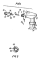
- Fig. 1 is an exploded perspective view of a hand pump sprayer in accordance with the invention.
- Fig. 2 is a section of the nozzle assembly for use in the invention looking down from the top.
- Fig. 3 is a sideview of the nozzle assembly for use in the invention.
- Fig. 4 is a front view of the nozzle assembly of the present invention.
- Fig. 5 is a front view of the nozzle cap according to the present invention.
- Fig. 6 is a section of an alternative embodiment of the nozzle assembly looking down from the top nozzle assembly.
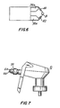
- Fig. 7 is a perspective view of a hand pump sprayer according to the invention having the nozzle assembly installed.
- the present invention is directed to an improved pan coating system for dispensing effective pan coatings without the use of hydrocarbon propellants or VOC solvents such as ethanol and without the use of water.
- a dispensing system for viscous pan coatings having a viscosity above 60 cps preferably from 60 cps to 100 cps most preferably from 70 to 85 cps is provided.
- a hand pump sprayer for pumping viscous liquids is provided.
- a spray nozzle is provided.
- a viscous pan coating preferably a vegetable oil, lecithin mixture of 1 to 15% lecithin and 99 to 85% vegetable oil is placed in a reservoir or container for pumping.
- a hand pump sprayer preferably of the trigger type is provided for delivering the pan coating under pressure from the container to a delivery passageway or conduit.
- a nozzle assembly is interconnected with the delivery conduit from the hand pump sprayer. Included within the nozzle assembly is a first and second passageway preferably conduits which are connected to the delivery conduit to split the pan coating exiting from the delivery conduit into two streams.
- the cross sectional flow area of the first and second conduits is smaller than the cross sectional flow area of the delivery passageway.
- cross sectional area of the flow path of the pan coating decreases as it passes from the delivery passageway to first and second passageway.
- some of the cross sectional area of the first and second passageway is between 1/200 (.005) and 1/2 (.5) of that of the delivery passageway and preferably between 1/100 (.01) and 1/4 (.25) of the cross sectional area of the delivery passageway and most preferably about 1/50 (0.02) the cross sectional area of the delivery passageway.
- the first and second conduits have a fluid outlet to the atmosphere.
- Each fluid outlet has a discharge axis such that the pan coating exiting the first fluid outlet intersects the pan coating exiting the second fluid outlet at a point exterior to the nozzle assembly.
- the pan coating exiting from the first outlet collides with the pan coating exiting from the second outlet to break the pan coating into small droplets and to form a wide angle spray of fine droplets preferably generally rectangular in nature for application to a cooking surface.
- Fig. 1 is an exploded perspective representation of a trigger type spray pumper according to the subject invention.
- a hand sprayer 10 of the trigger type which is operated by moving the trigger handle 12 back and forth to pump liquid from a container 14 through tube 16 to supply a fluid under pressure to delivery conduit 18, is provided.
- Particularly useful in the invention is continental Industrial Sprayer 922 which is modified in the nozzle area to accommodate the nozzle assembly hereinafter described. This sprayer is generally described in U.S. Patent No. 3,701,478.
- the trigger moves a piston reciprocally within a cylindrical chamber to provide fluid under pressure from a reservoir to a delivery channel.
- a nozzle assembly 30 having a fluid inlet 54 and fluid outlets 44 and 46 is inserted within delivery conduit 18 of hand pump sprayer 10 for receipt of pressured fluid preferably pan coating flowing in delivery conduit 18 upon the pumping of trigger 12.
- Nozzle assembly 30 has a generally tubular body 31 and snugly slips into delivery conduit 18 and receive the end of valve spring 70 which is connected to valve 72 associated with the pump sprayer. See for example, the pump sprayer of U.S. Patent No. 3,701,487 which is incorporated herein by reference.
- an annular collar 56 located between to inlet 54 and outlets 44 and 46, is provided to engage the side wall of sprayer housing 22 to prevent the nozzle assembly 30 from travelling too far into delivery conduit 18.
- Nozzle assembly 30 includes at its outlet end, projections 64 and 66 preferably twin projections which are separated by v-shaped notch 58. Outlets 44 and 46 are located at the top of the slanting side wall of v-shaped notch 58.
- Cap 20 includes annular member 68 which in installation will engage annular collar 56 to prevent nozzle assembly 30 from being dislodged from delivery conduit 18 during spraying.
- Nozzle cap 20 is provided for threaded mounting on the outside of sprayer housing 22. Referring to Fig. 4, nozzle cap 20 has a hollow threaded end 60 for mounting and threaded engagement about sprayer housing 22.
- Aperture 62 is provided for receipt of the head of nozzle assembly 30 which projects outwardly from nozzle cap 20 so that outlets 44 and 46 extend outside the top surface of the nozzle cap 20 to assure that the colliding pan coating and the resulting mist are not subjected to interference from the walls of nozzle cap 20.
- the nozzle assembly 30 has a wide channel 32 which is substantially the same diameter as that of the delivery conduit 18 aside from thin walls 34.
- the channel 32 can optionally be funnel shaped.
- a first fluid conduit 36 and a second fluid conduit 38 are provided to split the pan coating flowing through conduit 32 into two flowing paths.
- the cross sectional area of the first and second conduits 36 and 38 are smaller than the cross sectional area of conduit 32 and of delivery conduit 18.
- the conduits 36 and 38 are twins that is, each is the same size and the same cross sectional area and are located in the same location on the left and right side of channel 32. Desirably the sum of the cross sectional areas of conduits 36 and 38 is about 0.25 that of channel 32.
- the velocity of the pressurized pan coating from delivery conduit 18 is increased as a result of the restriction on the cross sectional flow area as it passes through the first and second conduits.
- a third conduit 40 and a fourth conduit 42 are provided at the end of conduits 36 and 38 to receive the speeded up pan coating flowing therein.
- Channels 40 and 42 have a cross sectional area smaller than that of channels 36 and 38.
- third conduit 40 and fourth conduit 42 are mirror images of one another.
- third conduit 40 is located in the same relative position to first conduit 36 as is fourth conduit 42 to second conduit 38.
- Desirably channels 40 and 42 have a cross sectional area which is about one-twelfth the cross sectional area of the first conduit 36 and second conduit 38.
- three or more passageways and outlets may be substituted for the two passageways shown to split the fluid into multiple paths. The discharge axises for the three or more passageways should then intersect as do the two passageways shown herein so that the exiting fluid paths collide.
- first and second conduits 36A and 38A can be generally rectangular in shape.
- the conduits can be tapered at the outlet end to more efficiently funnel the fluid to third and fourth conduits, 40 and 42.
- Fig. 7 shows the nozzle assembly in place in sprayer 10. Projections 64 and 66 of nozzle assembly 30 project outward from Cap 20 to deliver the pan coating. It should be noted that in Fig. 7 the projections have been rotated so that they may be seen in the Figure whereas in operation the projection would be generally horizontal, that is rotated 90° from the position in Fig. 7.
- the pump sprayer 10 delivers pressurized pan coating through delivery conduit 18 by the action of trigger 12 and associated pistons and valves.
- the pan coating then travels through wide channel 32 to first and second conduits 36 and 38, wherein pan coating velocity is increased.
- the pan coating then travels through third and fourth conduits 40 and 42 where its velocity once again increases.
- the pan coating is dispensed through outlets 44 and 46.
- the discharge axis 50 of conduit 40 and discharge axis 52 of conduit 42 are oriented such that the pan coating exiting outlets 44 and 46 intersect at a point 48 outside the nozzle assembly.
- the intersection point 48 is preferably within one-half inch of outlets 44 and 46 most preferably within one-quarter of an inch of outlets 44 and 46.
- the speeding pan coating from outlets 44 and 46 collides and is broken into small droplets to create a wide angled spray preferably in a generally rectangular pattern for coverage of the cooking area needing application.
- the angle formed by the intersection of the discharge axises and shown in Fig. 2 as ⁇ is referred to as the impingement angle.
- the third and fourth conduits 40 and 42 are oriented such that the discharge axis 50 and 52 form an impingement angle ⁇ which is from 10° to 170°. Preferably the angle is from 60° to 140°. An impingement angle of about 90° as shown in Fig. 2 is desirable.
- the pan coating is a vegetable oil, lecithin composition preferably from 1 to 15% lecithin and the remainder, vegetable oil.
- the pan coating most preferably is composed of 4 to 8% lecithin and the remaining vegetable oil.
- the vegetable oil component can be selected from a wide range of vegetable oils such as soybean oil, corn oil, safflower oil, sunflower oil, coconut oil, canola oil, olive oil, peanut oil; preferably a mixture of soybean oil and canola oil.
- the pan coating composition is 87 parts by weight soybean oil, 6 parts by weight canola oil and 6 parts by weight lecithin and has a viscosity of about 81 cps at 66° F.
- a spray nozzle was constructed according to the invention.
- the wide channel 32 had an inside diameter of 0.185 inches and a length of 0.29 inches.
- First and second conduits 36 and 38 had inside diameters of 0.062 inches and a length of 0.11 inches.
- Third and fourth conduits 40 and 42 had inside diameters of 0.018 inches and lengths of 0.06 inches.
- the angle of impingement ⁇ was about 90°.
- the resulting nozzle was installed in a Continental 922 trigger spray.
- the sprayability of a pan coating composed of about 7 percent lecithin and about 93 percent vegetable oil having a viscosity of about 81 cps at 66° was tested. The pan coating was easily sprayed upon pumping the trigger.
- the spray pattern was generally rectangular and covered a wide surface area with fine drops of pan coatings.
- pan coating dispensing system of Example 1 was superior to the Continental 922. There was a two-thirds decrease in the area where there was an undesirable high concentration of pan coating applied to the pan with the Example 1 system. In addition, there was a 40% increase in area covered per spray when using the Example 1 system.
Abstract
Description
- The field of the invention is vegetable oil based pan coatings and in particular a dispensing system for viscous pan coatings containing vegetable oil and lecithin.
- Lecithin has been recognized as an advantageous cooking lubricant and release agent. Commonly lecithin is combined with vegetable oil to provide a edible pan release agent. However, there have been difficulties encountered in providing a readily sprayable pan release agent. The lecithin, vegetable oil compositions have rather high viscosity and have proved difficult to pump. For example, a 90% vegetable oil (soybean oil) mixed with 10% lecithin would have an approximate viscosity at 66°F of 87 cps.
- Considerable efforts have been made to provide spray dispensable lecithin, vegetable oil compositions. Aerosol compositions have been provided in the prior art. Many of such compositions employ the use of chlorofluoro hydrocarbon propellant or other hydrocarbon propellants. For example, U.S. Patent No. 3,896,975 (Follmer) shows such an aerosol composition.
- Considering the possible harmful effects of fluorocarbons on the ozone layer, it is now desirable to avoid their uses in food products. Efforts to eliminate the use of the chlorofluoro hydrocarbons have resulted in the substitution of such propellant with isobutane or propane or other hydrocarbon propellants. In addition, it has been found to have a sprayable composition in such a form, it is necessary to dilute the composition with a solvent such as ethyl alcohol. See for example, U.S. Patent No. 4,188,412 (Sejpal). However, substitution of the chlorofluoro hydrocarbons with other hydrocarbons and the use of an ethyl alcohol solvent still results in the use of volatile hydrocarbons which can have adverse environmental effects and may be flammable. Ethyl alcohol is considered a volatile organic compound (VOC). It is environmentally desirable to remove VOC from products used by the consumer because VOC is a component of smog. Thus, it would be desirable to remove the aerosol hydrocarbon propellants and alcohol solvents altogether from pan coating and have a pump sprayable product.
- Pump sprayable pan coatings products have been developed in the prior art. It has been recognized that products having a viscosity in excess of 60 cps are not suitable for use in pump sprayers. See U.S. Patent No. 4,142,003 (Sejpal). This has created a problem in obtaining pump sprayable pan coating because pan coatings often have a viscosity in excess of 60 cps. Thus, for example the prior art shows that a 6% lecithin, 94 soybean oil composition has a viscosity of about 82 cps at 66°F, a 10% lecithin, 90% soybean oil composition has a viscosity of 87 cps at 66°F, and 100% soybean oil has a viscosity of 75 cps at 66° F. A viscosity of 60 cps is generally considered as the upper limit for pump spraying.
- Some prior art products have added ethyl alcohol as a diluent to reduce the viscosity of vegetable oil, lecithin composition to a point where it can be pump sprayed. See for example, U.S. Patent No. 4,142,003 (Sejpal) and U.S. Patent No. 4,127,419 (Szuhaj). Other diluents have been used to provide pump sprayable product for example, white mineral oil. See U.S. Patent No. 4,155,770 (Doumani). However, ethanol containing compositions can cause difficulties. The ethanol can be present in amounts up to 15%. Since ethanol is a VOC, it is an undesirable pollutant and a component of smog. In addition, the pan coatings sprays are used in cooking and the use of the ethanol can be an undesirable fire hazard. Thus, it would be desirable to remove all VOC from pan coatings.
- Water has been proposed as a diluent to provide a pump sprayable product. However, vegetable oil, water products have proved undesirable in the pump spray environment since the water promotes the growth of bacteria in the product. Thus, a pump sprayable system containing vegetable oil and lecithin which is water free and does not employ hydrocarbon pollutant diluents or hydrocarbons aerosol propellants would be a desirable product as a pan coating.
- Pump sprayers of the trigger type have been widely used to spray liquids. For example, U.S. Patent No. 3,701,478 (Tada) and U.S. Patent No. 4,646,969 (Tada) and U.S. Patent No. 4,591,077 (Corsette). However, such devices have proven ineffective for the application of a viscous pan coating which needs to be applied over a wide area as a mist without pooling.
- Nozzle devices for pressurized containers have been proposed where the fluid exits the nozzle from two outlets. The exits for the outlets are on skew lines such that the output of the orifices meets tangentially outside the nozzle. The resulting turbulence is said to effect the breakup of the particles or agglomerates of liquids or solids in the propelling gas stream. See U.S. Patent No. 3,406,913 (Frangos). Spray nozzles for fuel burners and water jets having converging jet passages outside the nozzle head are also shown in the prior art. See U.S. Patent No. 1,055,789 (Papa-Fedoroff), U.S. Patent No. 2,785,926 (Latase). Spray nozzles having converging jet-forming passages inside the nozzle head have also been proposed. U.S. Patent No. 3,568,933 (Benson).
- The present invention is directed to an improved pan coating dispensing system. The invention also relates to a method and apparatus for dispensing viscous pan coatings without the need to use aerosol propellants or to dilute the product with ethyl alcohol or other VOC pollutants. In addition, the hand pumpable, sprayable pan coating is water free and free of VOC's, and free of chlorofluoro hydrocarbons and is non-flammable. In another aspect of the invention a hand pump sprayer preferably of the trigger type is provided which is particularly useful on viscous fluids having a viscosity in excess of 60 cps. In addition, according to the invention, a spray nozzle is also provided.
- It is an object of the invention to provide a pan coating dispensing system which can dispense viscous pan coatings without the need to dilute the pan coating with VOC solvents such as ethanol.
- It is another object of the invention to provide pan. coatings dispensing system that is water free. It is an object of the invention to provide a pan coating system that is free of chlorofluoro hydrocarbon and other aerosol propellants.
- It is a further object of the invention to provide a hand pump sprayer which can readily spray viscous products having a viscosity over 60 cps in fine droplets.
- Other, further objects will become apparent from the Specifications, Drawings and Claims.
- According to the invention a dispensing system for viscous pan coatings is provided which includes a reservoir for holding a pan coating for dispensing. The viscous pan coating is preferably a lecithin, vegetable oil mixture having from 1 to 15% lecithin and 99 to 85% vegetable oil. A hand pump sprayer for delivering the pan coating under the pressure from reservoir preferably a container to a delivery conduit is provided. Preferably the hand pump sprayer is of the trigger type.
- A nozzle assembly is interconnected with the delivery passageway or conduit from the hand pump sprayer. The nozzle assembly has a first and second passageway, preferably conduits which are connected to the delivery passageway or conduit and splits the fluid preferably pan coating exiting from the delivery passageway or conduit into two streams. The cross sectional flow area of the first and second conduit means is smaller than the cross sectional flow area of the delivery conduit so that the velocity of the pan coating increases upon entry into the first and second conduits located in the nozzle assembly.
- Each conduit has a fluid outlet to the atmosphere which directs the fluid from the conduit to the atmosphere. The first and second conduits in combination with said fluid outlets define a discharge axis. The first fluid conduit discharge axis intersects the second fluid discharge axis at an impingement angle β of from 10° to 170° preferably from 60° to 140° so that the pan coating exiting each outlet intersects at a point exterior to the nozzle. As a result the pan coating exiting the first outlet collides with the pan coating exiting from the second outlet to break the pan coating into small droplets to form a wide angle mist for application to a cooking surface. The impingement angle should be sufficiently high so that there is sufficient collision of the streams to form fine drops while at the same time preserving a sufficient forward velocity so that the pan coating can be sprayed on a cooking surface between 6 inches and 24 inches from the nozzle.
- Desirably, the reduction in the cross sectional area between the delivery passageway and the fluid outlets is about 1/2 to 1/200 of the cross sectional area of the delivery passageway. Preferably this reduction is from 1/4 to 1/100 and desirably about 1/50.
- According to another aspect of the invention, a third and fourth passageway preferably conduits are provided which are located in the nozzle assembly. The third and fourth conduits are connected to the first and second conduits intermediate the first and second conduits and the first and second fluid outlets. The third and fourth conduits have a smaller cross sectional flow area than does the first and second conduits so that the velocity of the pan coating travelling from the first and second conduit into the third and fourth conduit increases. According to this embodiment prior to reaching the fluid outlets, the velocity of the pan coating is increased from the discharge conduit provided from the hand pump sprayer two times, once in the discharge to the first and second conduit, from the delivery conduit or passageway and a second time from the discharge from the first and second conduit to the smaller third and fourth conduits. The resulting pan coating dispensing system can dispense viscous pan coatings having viscosity above 60 cps in fine drops to provide improved spray coverage for the cooking surface.
- In another aspect of the invention, a hand pump sprayer of the trigger type is provided which is particularly useful for the spraying of viscous fluids, particularly those having a viscosity of greater than 60 cps. The hand pump sprayer includes the nozzle assembly described above.
- In still a further aspect of the invention, a nozzle assembly for introduction into hand pump spray dispensers as described above is provided.
- The preferred embodiment of the present invention is illustrated in the drawings and examples. However, it should be expressly understood that the present invention should not be limited solely to the illustrative embodiment.
- Fig. 1 is an exploded perspective view of a hand pump sprayer in accordance with the invention.
- Fig. 2 is a section of the nozzle assembly for use in the invention looking down from the top.
- Fig. 3 is a sideview of the nozzle assembly for use in the invention.
- Fig. 4 is a front view of the nozzle assembly of the present invention.
- Fig. 5 is a front view of the nozzle cap according to the present invention.
- Fig. 6 is a section of an alternative embodiment of the nozzle assembly looking down from the top nozzle assembly.
- Fig. 7 is a perspective view of a hand pump sprayer according to the invention having the nozzle assembly installed.
- The present invention is directed to an improved pan coating system for dispensing effective pan coatings without the use of hydrocarbon propellants or VOC solvents such as ethanol and without the use of water. According to the invention, a dispensing system for viscous pan coatings having a viscosity above 60 cps preferably from 60 cps to 100 cps most preferably from 70 to 85 cps is provided. In another aspect of the invention a hand pump sprayer for pumping viscous liquids is provided. In a still further aspect of the invention a spray nozzle is provided.
- A viscous pan coating, preferably a vegetable oil, lecithin mixture of 1 to 15% lecithin and 99 to 85% vegetable oil is placed in a reservoir or container for pumping. A hand pump sprayer preferably of the trigger type is provided for delivering the pan coating under pressure from the container to a delivery passageway or conduit. A nozzle assembly is interconnected with the delivery conduit from the hand pump sprayer. Included within the nozzle assembly is a first and second passageway preferably conduits which are connected to the delivery conduit to split the pan coating exiting from the delivery conduit into two streams. The cross sectional flow area of the first and second conduits is smaller than the cross sectional flow area of the delivery passageway. As a result the velocity of the flowing pan coating is speeded up as it travels through the first and second conduits.
- According to the invention of cross sectional area of the flow path of the pan coating decreases as it passes from the delivery passageway to first and second passageway. Preferably some of the cross sectional area of the first and second passageway is between 1/200 (.005) and 1/2 (.5) of that of the delivery passageway and preferably between 1/100 (.01) and 1/4 (.25) of the cross sectional area of the delivery passageway and most preferably about 1/50 (0.02) the cross sectional area of the delivery passageway.
- The first and second conduits have a fluid outlet to the atmosphere. Each fluid outlet has a discharge axis such that the pan coating exiting the first fluid outlet intersects the pan coating exiting the second fluid outlet at a point exterior to the nozzle assembly. As a result the pan coating exiting from the first outlet collides with the pan coating exiting from the second outlet to break the pan coating into small droplets and to form a wide angle spray of fine droplets preferably generally rectangular in nature for application to a cooking surface.
- Referring now to the drawings, Fig. 1 is an exploded perspective representation of a trigger type spray pumper according to the subject invention. According to the invention, a
hand sprayer 10 of the trigger type which is operated by moving the trigger handle 12 back and forth to pump liquid from acontainer 14 throughtube 16 to supply a fluid under pressure todelivery conduit 18, is provided. Particularly useful in the invention is continental Industrial Sprayer 922 which is modified in the nozzle area to accommodate the nozzle assembly hereinafter described. This sprayer is generally described in U.S. Patent No. 3,701,478. In the 922 sprayer, the trigger moves a piston reciprocally within a cylindrical chamber to provide fluid under pressure from a reservoir to a delivery channel. - Referring to Figs. 1 and 2 and as best seen in Fig. 2, a
nozzle assembly 30 having afluid inlet 54 andfluid outlets delivery conduit 18 ofhand pump sprayer 10 for receipt of pressured fluid preferably pan coating flowing indelivery conduit 18 upon the pumping of trigger 12.Nozzle assembly 30 has a generallytubular body 31 and snugly slips intodelivery conduit 18 and receive the end of valve spring 70 which is connected tovalve 72 associated with the pump sprayer. See for example, the pump sprayer of U.S. Patent No. 3,701,487 which is incorporated herein by reference. Preferably integral with thenozzle assembly 30, anannular collar 56, located between toinlet 54 andoutlets sprayer housing 22 to prevent thenozzle assembly 30 from travelling too far intodelivery conduit 18.Nozzle assembly 30 includes at its outlet end,projections notch 58.Outlets notch 58. -
Cap 20 includesannular member 68 which in installation will engageannular collar 56 to preventnozzle assembly 30 from being dislodged fromdelivery conduit 18 during spraying.Nozzle cap 20 is provided for threaded mounting on the outside ofsprayer housing 22. Referring to Fig. 4,nozzle cap 20 has a hollow threadedend 60 for mounting and threaded engagement aboutsprayer housing 22.Aperture 62 is provided for receipt of the head ofnozzle assembly 30 which projects outwardly fromnozzle cap 20 so thatoutlets nozzle cap 20 to assure that the colliding pan coating and the resulting mist are not subjected to interference from the walls ofnozzle cap 20. - The
nozzle assembly 30 has awide channel 32 which is substantially the same diameter as that of thedelivery conduit 18 aside fromthin walls 34. Thechannel 32 can optionally be funnel shaped. A firstfluid conduit 36 and a secondfluid conduit 38 are provided to split the pan coating flowing throughconduit 32 into two flowing paths. The cross sectional area of the first andsecond conduits conduit 32 and ofdelivery conduit 18. Preferably theconduits channel 32. Desirably the sum of the cross sectional areas ofconduits channel 32. The velocity of the pressurized pan coating fromdelivery conduit 18 is increased as a result of the restriction on the cross sectional flow area as it passes through the first and second conduits. - A
third conduit 40 and afourth conduit 42 are provided at the end ofconduits Channels channels third conduit 40 andfourth conduit 42 are mirror images of one another. Preferablythird conduit 40 is located in the same relative position tofirst conduit 36 as isfourth conduit 42 tosecond conduit 38. Most preferablythird conduit 40 andfourth conduit 42 and both the same size and have the same cross sectional area.Desirably channels first conduit 36 andsecond conduit 38. As a result, the velocity of the pan coating fluid traveling throughthird conduit 40 andfourth conduit 42, increases. Optionally three or more passageways and outlets may be substituted for the two passageways shown to split the fluid into multiple paths. The discharge axises for the three or more passageways should then intersect as do the two passageways shown herein so that the exiting fluid paths collide. - Optionally as shown in Figs. 6 the first and second conduits 36A and 38A can be generally rectangular in shape. The conduits can be tapered at the outlet end to more efficiently funnel the fluid to third and fourth conduits, 40 and 42.
- Fig. 7 shows the nozzle assembly in place in
sprayer 10.Projections nozzle assembly 30 project outward fromCap 20 to deliver the pan coating. It should be noted that in Fig. 7 the projections have been rotated so that they may be seen in the Figure whereas in operation the projection would be generally horizontal, that is rotated 90° from the position in Fig. 7. - In operation the
pump sprayer 10 delivers pressurized pan coating throughdelivery conduit 18 by the action of trigger 12 and associated pistons and valves. The pan coating then travels throughwide channel 32 to first andsecond conduits fourth conduits outlets discharge axis 50 ofconduit 40 anddischarge axis 52 ofconduit 42 are oriented such that the pancoating exiting outlets outlets outlets outlets - The angle formed by the intersection of the discharge axises and shown in Fig. 2 as β is referred to as the impingement angle. The third and
fourth conduits discharge axis - Desirably, the pan coating is a vegetable oil, lecithin composition preferably from 1 to 15% lecithin and the remainder, vegetable oil. The pan coating most preferably is composed of 4 to 8% lecithin and the remaining vegetable oil. The vegetable oil component can be selected from a wide range of vegetable oils such as soybean oil, corn oil, safflower oil, sunflower oil, coconut oil, canola oil, olive oil, peanut oil; preferably a mixture of soybean oil and canola oil. Most preferably the pan coating composition is 87 parts by weight soybean oil, 6 parts by weight canola oil and 6 parts by weight lecithin and has a viscosity of about 81 cps at 66° F.
- A spray nozzle was constructed according to the invention. The
wide channel 32 had an inside diameter of 0.185 inches and a length of 0.29 inches. First andsecond conduits fourth conduits - A comparison of two different pan coating dispensing systems was made. VEGALENE brand pan coating which is 6 to 7% lecithin, 93 to 94% vegetable oil, was sprayed with the Continental 922 sprayer and with the sprayer of Example 1. A pan 13" x 18" was used in the test. The pan coating was sprayed at a distance of 10" from the pan. The results of the tests were as follows:

- As shown in the above data, the pan coating dispensing system of Example 1 was superior to the Continental 922. There was a two-thirds decrease in the area where there was an undesirable high concentration of pan coating applied to the pan with the Example 1 system. In addition, there was a 40% increase in area covered per spray when using the Example 1 system.
- The foregoing is considered as illustrative only to the principles of the invention. Further, since numerous changes and modifications will occur to those skilled in the art, it is not desired to limit the invention to the exact construction and operation shown and described above, and accordingly all suitable modifications and equivalents may be resorted to, falling within the scope of the invention.
Claims (20)
- A hand pump sprayer of the trigger type wherein pressurized fluid is brought from a reservoir to the outlet of a delivery passageway, said sprayer comprising:
a nozzle assembly having an inlet and an outlet end;
said nozzle assembly inlet interconnected with said delivery conduit outlet;
a first and second passageway located in said nozzle assembly to split the fluid in said delivery passageway into two streams;
each said first and second passageway having a cross sectional area less than one half the cross sectional of the delivery passageway so that the velocity of said fluid increases in the first and second passageway from its velocity in said delivery passageway;
a first and second discharge means in fluid communication with said first and second passageway and having a discharge axis to dispense the fluid from said nozzle assembly;
said discharge axis of first discharge means and said discharge axis of said second discharge means intersecting at a collision point exterior to said nozzle assembly so that when said fluid is pumped from said reservoir and discharged to the atmosphere the fluid exiting from said first discharge means collides with the fluid exiting from said second discharge means to break the fluid into small droplets to form a wide angle mist for application to a surface. - Sprayer according to claim 1 wherein the fluid is a pan coating composed of a vegetable oil, lecithin mixture having 1 % to 15 % lecithin and 99 % to 85 % vegetable oil.
- Sprayer according to claim 1 or 2 further comprising:
a third and fourth passageway located in said nozzle assembly adjacent to and in fluid communication with said first and second passageway;
the cross sectional areas of said third and fourth passageway being smaller than that of said first and second passageway so that the velocity of the fluid increases from its velocity in said first and second passageway;
said third and fourth passageway located intermediate to said first and second passageway and said first and second discharge means. - Sprayer according to any of claims 1 to 3 wherein said first and second passageway are conduit means.
- Sprayer according to any of claims 1 to 4 wherein said third and fourth passageways are conduit means.
- Sprayer according to any of claims 1 to 5 wherein the sum of cross sectional areas of said first conduit and said second conduit is from 1/2 to 1/200 of the cross sectional area of said delivery passageway.
- Sprayer according to any of claims 1 to 6 wherein the sum of the cross sectional areas of said first and second conduit is 1/4 to 1/100 of the cross sectional area of said delivery passageway.
- Sprayer according to any of claims 1 to 7 wherein the sum of the cross sectional areas of said first and second conduits is 1/4 to about 1/50 of the cross sectional area of said delivery passageway.
- Sprayer according to any of claims 1 to 8 wherein the cross sectional areas of said third and fourth conduits is between 1/2 and 1/200 of the cross sectional area of said delivery passageway.
- Sprayer according to any of claims 1 to 9 wherein the first and second conduits are the same size and the sum of the cross sectional areas of said first and second conduits is about one-quarter of the cross sectional area of the delivery conduits.
- Sprayer according to any of claims 1 to 10 wherein the cross sectional area of said third conduit is about one-twelfth the cross sectional area of said first conduit and the cross sectional area of said fourth conduit is about one-twelfth of the cross sectional area of the second conduit.
- Sprayer according to any of claims 1 to 11 wherein said collision point is located less than one-half inch from said first and second discharge means.
- Sprayer according to any of claims 1 to 12 wherein said collision point is located about one-quarter inch from said discharge means.
- Sprayer according to any of claims 1 to 13 further comprising an annular collar located on said nozzle assembly to hold said nozzle assembly in fluid communication with said delivery passageway.
- Sprayer according to any of claims 1 to 14 further comprising:
a first projection and a second projection located on the outlet end of said nozzle assembly;
a v-shaped notch separating said first and second projections;
said first and second discharge means located on opposite side walls of said v-shaped notch. - Sprayer according to any of claims 1 to 15 further comprising:
a threaded sprayer housing surrounding said delivery conduit;
a nozzle cap for threaded engagement on said threaded spray housing;
said nozzle cap having an aperture for receiving said projections so that said projections protrude from the surface of said cap;
an annular sleeve integral with and adjacent to the top of said cap for engagement of said annular collar of said nozzle assembly to prevent outward movement of said nozzle assembly during spraying. - Sprayer according to any of claims 1 to 16 wherein said colliding fluid provides a generally rectangular spray pattern.
- Sprayer according to any of claims 1 to 17 further comprising a trigger for moving a piston reciprocally within a cylindrical chamber to provide the liquid to be sprayed under pressure to a delivery channel.
- Sprayer according to any of claims 1 to 18 wherein the impingement angle β is from 10° to 170°, preferably from 60° to 140°, and further preferred about 90°.
- Dispensing system for the application of a fluid to a cooking surface, comprising a sprayer according to any one of claims 1 to 19 and a reservoir for holding said fluid for dispensing.
Applications Claiming Priority (3)
| Application Number | Priority Date | Filing Date | Title |
|---|---|---|---|
| US553786 | 1983-11-18 | ||
| US07/553,786 US5088649A (en) | 1990-07-12 | 1990-07-12 | Pump sprayable dispensing system for vegetable oil based pan coatings |
| CA002055240A CA2055240C (en) | 1990-07-12 | 1991-11-13 | Pump sprayable dispensing system for vegetable oil based pan coatings |
Publications (3)
| Publication Number | Publication Date |
|---|---|
| EP0466157A2 true EP0466157A2 (en) | 1992-01-15 |
| EP0466157A3 EP0466157A3 (en) | 1992-07-15 |
| EP0466157B1 EP0466157B1 (en) | 1996-01-31 |
Family
ID=25674852
Family Applications (1)
| Application Number | Title | Priority Date | Filing Date |
|---|---|---|---|
| EP91111565A Expired - Lifetime EP0466157B1 (en) | 1990-07-12 | 1991-07-11 | Pump sprayable dispensing system for vegetable oil based pan coatings |
Country Status (3)
| Country | Link |
|---|---|
| US (1) | US5088649A (en) |
| EP (1) | EP0466157B1 (en) |
| CA (1) | CA2055240C (en) |
Cited By (10)
| Publication number | Priority date | Publication date | Assignee | Title |
|---|---|---|---|---|
| WO1995005244A1 (en) * | 1993-08-18 | 1995-02-23 | The Procter & Gamble Company | Improved atomization systems for high viscosity products |
| WO1995008400A1 (en) * | 1993-09-22 | 1995-03-30 | The Procter & Gamble Company | High pressure atomization systems for high viscosity products |
| US5516045A (en) * | 1992-05-21 | 1996-05-14 | L'oreal | Pushbutton intended to be fitted to a valve or a pump equipping a dispenser, and dispenser including such a pushbutton |
| WO1997002896A1 (en) * | 1995-07-07 | 1997-01-30 | The Procter & Gamble Company | Pump sprayer for viscous or solids laden liquids |
| US5639025A (en) * | 1995-07-07 | 1997-06-17 | The Procter & Gamble Company | High Viscosity pump sprayer utilizing fan spray nozzle |
| US5890655A (en) * | 1997-01-06 | 1999-04-06 | The Procter & Gamble Company | Fan spray nozzles having elastomeric dome-shaped tips |
| WO2005097345A1 (en) * | 2004-04-05 | 2005-10-20 | Andrey Leonidovich Dushkin | Liquid atomizer |
| EP2189224A1 (en) | 2008-11-22 | 2010-05-26 | Grundfos Management A/S | Jet |
| WO2016075433A1 (en) * | 2014-11-14 | 2016-05-19 | The Technology Partnership Plc | Low cost impinging jet nozzle |
| KR20230110724A (en) * | 2022-01-11 | 2023-07-25 | 가부시키가이샤 사이엔스 | mist generating nozzle |
Families Citing this family (26)
| Publication number | Priority date | Publication date | Assignee | Title |
|---|---|---|---|---|
| SG45171A1 (en) * | 1990-03-21 | 1998-01-16 | Boehringer Ingelheim Int | Atomising devices and methods |
| US5249747A (en) * | 1990-07-12 | 1993-10-05 | Par-Way Group | Sprayable dispensing system for viscous vegetable oils and apparatus therefor |
| IL100224A (en) * | 1990-12-04 | 1994-10-21 | Dmw Tech Ltd | Atomising nozzles |
| AU659618B2 (en) * | 1990-12-04 | 1995-05-25 | Boeringer Ingelheim International Gmbh | Nozzle assembly for preventing back-flow |
| CA2120357A1 (en) * | 1991-10-08 | 1993-04-15 | Edwin I. Stoltz | Non-aerosol, uniform spray dispersion system for oil-based products |
| US5492275A (en) * | 1994-05-16 | 1996-02-20 | Par-Way Group | Hand pump sprayer with rotating nozzle and system for dispensing viscous liquids |
| US5740964A (en) * | 1994-05-16 | 1998-04-21 | Par-Way Group | Hand held spray dispenser with adjustable pressure delivery system and rotating nozzle |
| US5570840A (en) * | 1994-10-14 | 1996-11-05 | Fourth And Long, Inc. | Hand-held spraying apparatus |
| US5779156A (en) * | 1995-11-13 | 1998-07-14 | Par-Way Group | Spray dispenser and system for spraying viscous liquids |
| US5718383A (en) * | 1996-02-29 | 1998-02-17 | Par Way Group | Viscous liquid spray dispensing systems |
| US5829682A (en) * | 1996-04-26 | 1998-11-03 | Spraying Systems Co. | Air-assisted spray nozzle assembly |
| US5890661A (en) * | 1996-11-27 | 1999-04-06 | Par-Way Group | Colliding stream spray dispensing system with a moldable nozzle |
| US5753310A (en) * | 1997-04-29 | 1998-05-19 | Bakalar; Marvin | Protective coating for vehicles |
| US5964380A (en) * | 1997-08-07 | 1999-10-12 | University Of Massachussets | Viscous liquid applicator |
| AU3490999A (en) * | 1999-01-11 | 2000-08-01 | Graves Spray Supply, Inc. | Liquid impingement nozzle with paired openings |
| US6365211B1 (en) * | 1999-06-18 | 2002-04-02 | The Procter & Gamble Co. | Cooking aid with reduced foaming |
| GB0012356D0 (en) * | 2000-05-22 | 2000-07-12 | Textron Automotive Company Lim | Fluid spray nozzle |
| US6484923B2 (en) | 2001-02-27 | 2002-11-26 | Miguel Figueroa-Rivera | Hand held flux and solder feeding tool |
| NZ525880A (en) * | 2003-05-14 | 2005-11-25 | Methven Ltd | Method and apparatus for producing droplet spray |
| US6817493B1 (en) * | 2003-08-22 | 2004-11-16 | S. C. Johnson & Son, Inc. | Spray nozzle |
| US7219849B1 (en) * | 2005-12-13 | 2007-05-22 | Graves Spray Supply, Inc. | Liquid impingement nozzle with paired openings |
| US8210399B2 (en) * | 2007-11-27 | 2012-07-03 | Conagra Foods Rdm, Inc. | Spray dispenser |
| US9138753B1 (en) | 2010-09-02 | 2015-09-22 | Hiroshi Takahara | Spray nozzle and the application |
| FR2984857B1 (en) * | 2011-12-23 | 2015-02-13 | Rexam Dispensing Sys | PUSH BUTTON FOR A SYSTEM FOR DISTRIBUTING A PRESSURIZED PRODUCT |
| DE102016014269A1 (en) | 2016-11-30 | 2018-05-30 | Dürr Systems Ag | Nozzle device with at least two nozzle plates and at least three openings |
| DE102016014270A1 (en) * | 2016-11-30 | 2018-05-30 | Dürr Systems Ag | A nozzle device for emitting two approaching jets of a delivery medium |
Citations (3)
| Publication number | Priority date | Publication date | Assignee | Title |
|---|---|---|---|---|
| US3406913A (en) * | 1966-09-01 | 1968-10-22 | Revlon | Mechanical break-up actuator for fluid dispensers |
| FR2495022A1 (en) * | 1980-12-01 | 1982-06-04 | Bailly Comte Ets | Spray gun with moulded head - is integral with hand lever which displaces piston to lift sprung piston valve off seat and permit spray through piston cap |
| FR2558743A3 (en) * | 1984-01-26 | 1985-08-02 | Fumakilla Ltd | PUSH BUTTON SPRAYER |
Family Cites Families (16)
| Publication number | Priority date | Publication date | Assignee | Title |
|---|---|---|---|---|
| US1055789A (en) * | 1911-12-30 | 1913-03-11 | Michael Papa-Fedoroff | Fuel-spray diffuser. |
| US2302021A (en) * | 1941-11-06 | 1942-11-17 | Rockwood Sprinkler Co | Nozzle for generating fog |
| FR1087714A (en) * | 1953-11-23 | 1955-02-28 | Spray method and device | |
| US2742326A (en) * | 1953-11-23 | 1956-04-17 | Borges Florentino | Atomizer heads |
| US2812213A (en) * | 1956-02-16 | 1957-11-05 | James A Bede | Spray nozzle |
| US2930532A (en) * | 1958-12-19 | 1960-03-29 | Oce W Johnson | Spray gun nozzle |
| US3125298A (en) * | 1963-01-31 | 1964-03-17 | Harukichi iwata | |
| US3366337A (en) * | 1965-05-27 | 1968-01-30 | Binks Mfg Co | Airless spray gun using diametrically opposed impingement orifices |
| US3568933A (en) * | 1969-03-05 | 1971-03-09 | Oxford Ind Group | Spray nozzles |
| US3701478A (en) * | 1970-10-08 | 1972-10-31 | Tetsuya Tada | Hand sprayer |
| US3761022A (en) * | 1972-04-04 | 1973-09-25 | H Kondo | A spring pressure accumulative spray device |
| US4127419A (en) * | 1977-01-12 | 1978-11-28 | Central Soya Company, Inc. | Pan release agent |
| US4142003A (en) * | 1977-08-22 | 1979-02-27 | American Home Products Corporation | Non-aerosol vegetable oil compositions containing lecithin and pure ethyl alcohol |
| US4155770A (en) * | 1978-04-03 | 1979-05-22 | Blue Cross Laboratories | Mineral oil modified lecithin cookware spray composition |
| CS242610B1 (en) * | 1982-11-19 | 1986-05-15 | Miloslav Sorm | Double acting mechanical pump for liquid spray |
| US4591077A (en) * | 1985-01-28 | 1986-05-27 | Corsette Douglas Frank | Continuous discharge dispenser |
-
1990
- 1990-07-12 US US07/553,786 patent/US5088649A/en not_active Expired - Lifetime
-
1991
- 1991-07-11 EP EP91111565A patent/EP0466157B1/en not_active Expired - Lifetime
- 1991-11-13 CA CA002055240A patent/CA2055240C/en not_active Expired - Lifetime
Patent Citations (3)
| Publication number | Priority date | Publication date | Assignee | Title |
|---|---|---|---|---|
| US3406913A (en) * | 1966-09-01 | 1968-10-22 | Revlon | Mechanical break-up actuator for fluid dispensers |
| FR2495022A1 (en) * | 1980-12-01 | 1982-06-04 | Bailly Comte Ets | Spray gun with moulded head - is integral with hand lever which displaces piston to lift sprung piston valve off seat and permit spray through piston cap |
| FR2558743A3 (en) * | 1984-01-26 | 1985-08-02 | Fumakilla Ltd | PUSH BUTTON SPRAYER |
Cited By (12)
| Publication number | Priority date | Publication date | Assignee | Title |
|---|---|---|---|---|
| US5516045A (en) * | 1992-05-21 | 1996-05-14 | L'oreal | Pushbutton intended to be fitted to a valve or a pump equipping a dispenser, and dispenser including such a pushbutton |
| WO1995005244A1 (en) * | 1993-08-18 | 1995-02-23 | The Procter & Gamble Company | Improved atomization systems for high viscosity products |
| WO1995008400A1 (en) * | 1993-09-22 | 1995-03-30 | The Procter & Gamble Company | High pressure atomization systems for high viscosity products |
| WO1997002896A1 (en) * | 1995-07-07 | 1997-01-30 | The Procter & Gamble Company | Pump sprayer for viscous or solids laden liquids |
| US5639025A (en) * | 1995-07-07 | 1997-06-17 | The Procter & Gamble Company | High Viscosity pump sprayer utilizing fan spray nozzle |
| US5642860A (en) * | 1995-07-07 | 1997-07-01 | The Procter & Gamble Company | Pump sprayer for viscous or solids laden liquids |
| CN1073471C (en) * | 1995-07-07 | 2001-10-24 | Ach食品有限公司 | Pump sprayer for viscous or solid laden liquids |
| US5890655A (en) * | 1997-01-06 | 1999-04-06 | The Procter & Gamble Company | Fan spray nozzles having elastomeric dome-shaped tips |
| WO2005097345A1 (en) * | 2004-04-05 | 2005-10-20 | Andrey Leonidovich Dushkin | Liquid atomizer |
| EP2189224A1 (en) | 2008-11-22 | 2010-05-26 | Grundfos Management A/S | Jet |
| WO2016075433A1 (en) * | 2014-11-14 | 2016-05-19 | The Technology Partnership Plc | Low cost impinging jet nozzle |
| KR20230110724A (en) * | 2022-01-11 | 2023-07-25 | 가부시키가이샤 사이엔스 | mist generating nozzle |
Also Published As
| Publication number | Publication date |
|---|---|
| CA2055240C (en) | 1994-08-16 |
| EP0466157B1 (en) | 1996-01-31 |
| CA2055240A1 (en) | 1993-05-14 |
| EP0466157A3 (en) | 1992-07-15 |
| US5088649A (en) | 1992-02-18 |
Similar Documents
| Publication | Publication Date | Title |
|---|---|---|
| US5088649A (en) | Pump sprayable dispensing system for vegetable oil based pan coatings | |
| US5249747A (en) | Sprayable dispensing system for viscous vegetable oils and apparatus therefor | |
| US6056213A (en) | Modular system for atomizing a liquid | |
| US5645198A (en) | Spray texturing apparatus and method | |
| US8820665B2 (en) | Fluid dispensing nozzle | |
| US7237697B2 (en) | Apparatus for dispensing an atomized liquid product | |
| US5388766A (en) | High pressure atomization systems for high viscosity products | |
| CN106999958B (en) | Spray nozzle for high viscosity (e.g. oil) spray applications with uniform spray distribution | |
| US3764069A (en) | Method and apparatus for spraying | |
| US6042025A (en) | Two hole dispenser with baffles | |
| KR0128257B1 (en) | Dip tube vapor tap compressed gas aerosol system | |
| CA2637867C (en) | Aerosol dispenser assembly having voc-free propellant and dispensing mechanism therefor | |
| EP0684081A1 (en) | Hand pump sprayer with rotating nozzle and system for dispensing viscous liquids | |
| US5722598A (en) | Spraying nozzle for regulating the rate of flow per unit of time | |
| US5890661A (en) | Colliding stream spray dispensing system with a moldable nozzle | |
| CN1201408A (en) | High pressure swirl atomizer | |
| US20200139385A1 (en) | Aerosol nozzle assembly and nozzle cup member for spraying viscous newtonian fluids | |
| US20120126034A1 (en) | Impingement Mixing Liquid Dispensing Apparatus and Methods | |
| JP2010540372A (en) | System for pressurized delivery of fluid | |
| JPS60232265A (en) | Air type spray nozzle device | |
| KR950700127A (en) | CONSUMER PRODUCT PACKAGE INCORPORATIMG A SPRAY DEVICE UTILIZING LARGE DIAMETER BUBBLES | |
| KR100353177B1 (en) | A fire fighting installation for discharging a liquid-gas fog | |
| US3635400A (en) | Paint spraying method and apparatus | |
| US20070278327A1 (en) | Fluids mixing nozzle | |
| US5779156A (en) | Spray dispenser and system for spraying viscous liquids |
Legal Events
| Date | Code | Title | Description |
|---|---|---|---|
| PUAI | Public reference made under article 153(3) epc to a published international application that has entered the european phase |
Free format text: ORIGINAL CODE: 0009012 |
|
| AK | Designated contracting states |
Kind code of ref document: A2 Designated state(s): AT BE CH DE DK ES FR GB GR IT LI LU NL SE |
|
| PUAL | Search report despatched |
Free format text: ORIGINAL CODE: 0009013 |
|
| AK | Designated contracting states |
Kind code of ref document: A3 Designated state(s): AT BE CH DE DK ES FR GB GR IT LI LU NL SE |
|
| 17P | Request for examination filed |
Effective date: 19921223 |
|
| 17Q | First examination report despatched |
Effective date: 19940225 |
|
| GRAA | (expected) grant |
Free format text: ORIGINAL CODE: 0009210 |
|
| AK | Designated contracting states |
Kind code of ref document: B1 Designated state(s): AT BE CH DE DK ES FR GB GR IT LI LU NL SE |
|
| PG25 | Lapsed in a contracting state [announced via postgrant information from national office to epo] |
Ref country code: LI Effective date: 19960131 Ref country code: AT Effective date: 19960131 Ref country code: NL Free format text: LAPSE BECAUSE OF FAILURE TO SUBMIT A TRANSLATION OF THE DESCRIPTION OR TO PAY THE FEE WITHIN THE PRESCRIBED TIME-LIMIT Effective date: 19960131 Ref country code: CH Effective date: 19960131 Ref country code: DK Effective date: 19960131 Ref country code: ES Free format text: THE PATENT HAS BEEN ANNULLED BY A DECISION OF A NATIONAL AUTHORITY Effective date: 19960131 Ref country code: GR Free format text: LAPSE BECAUSE OF FAILURE TO SUBMIT A TRANSLATION OF THE DESCRIPTION OR TO PAY THE FEE WITHIN THE PRESCRIBED TIME-LIMIT Effective date: 19960131 |
|
| REF | Corresponds to: |
Ref document number: 133588 Country of ref document: AT Date of ref document: 19960215 Kind code of ref document: T |
|
| ITF | It: translation for a ep patent filed |
Owner name: PROROGA CONCESSA IN DATA: 01.04.96;JACOBACCI & PER |
|
| REF | Corresponds to: |
Ref document number: 69116754 Country of ref document: DE Date of ref document: 19960314 |
|
| PG25 | Lapsed in a contracting state [announced via postgrant information from national office to epo] |
Ref country code: SE Effective date: 19960430 |
|
| ET | Fr: translation filed | ||
| NLV1 | Nl: lapsed or annulled due to failure to fulfill the requirements of art. 29p and 29m of the patents act | ||
| PG25 | Lapsed in a contracting state [announced via postgrant information from national office to epo] |
Ref country code: LU Free format text: LAPSE BECAUSE OF NON-PAYMENT OF DUE FEES Effective date: 19960731 |
|
| REG | Reference to a national code |
Ref country code: CH Ref legal event code: PL |
|
| PLBE | No opposition filed within time limit |
Free format text: ORIGINAL CODE: 0009261 |
|
| STAA | Information on the status of an ep patent application or granted ep patent |
Free format text: STATUS: NO OPPOSITION FILED WITHIN TIME LIMIT |
|
| 26N | No opposition filed | ||
| REG | Reference to a national code |
Ref country code: GB Ref legal event code: IF02 |
|
| PGFP | Annual fee paid to national office [announced via postgrant information from national office to epo] |
Ref country code: FR Payment date: 20050719 Year of fee payment: 15 |
|
| PGFP | Annual fee paid to national office [announced via postgrant information from national office to epo] |
Ref country code: BE Payment date: 20050725 Year of fee payment: 15 |
|
| PGFP | Annual fee paid to national office [announced via postgrant information from national office to epo] |
Ref country code: DE Payment date: 20050831 Year of fee payment: 15 |
|
| PG25 | Lapsed in a contracting state [announced via postgrant information from national office to epo] |
Ref country code: BE Free format text: LAPSE BECAUSE OF NON-PAYMENT OF DUE FEES Effective date: 20060731 |
|
| PGFP | Annual fee paid to national office [announced via postgrant information from national office to epo] |
Ref country code: IT Payment date: 20060731 Year of fee payment: 16 |
|
| PG25 | Lapsed in a contracting state [announced via postgrant information from national office to epo] |
Ref country code: DE Free format text: LAPSE BECAUSE OF NON-PAYMENT OF DUE FEES Effective date: 20070201 |
|
| REG | Reference to a national code |
Ref country code: FR Ref legal event code: ST Effective date: 20070330 |
|
| BERE | Be: lapsed |
Owner name: *PAR-WAY GROUP Effective date: 20060731 |
|
| PG25 | Lapsed in a contracting state [announced via postgrant information from national office to epo] |
Ref country code: FR Free format text: LAPSE BECAUSE OF NON-PAYMENT OF DUE FEES Effective date: 20060731 |
|
| PG25 | Lapsed in a contracting state [announced via postgrant information from national office to epo] |
Ref country code: IT Free format text: LAPSE BECAUSE OF NON-PAYMENT OF DUE FEES Effective date: 20070711 |
|
| PGFP | Annual fee paid to national office [announced via postgrant information from national office to epo] |
Ref country code: GB Payment date: 20100727 Year of fee payment: 20 |
|
| REG | Reference to a national code |
Ref country code: GB Ref legal event code: PE20 Expiry date: 20110710 |
|
| PG25 | Lapsed in a contracting state [announced via postgrant information from national office to epo] |
Ref country code: GB Free format text: LAPSE BECAUSE OF EXPIRATION OF PROTECTION Effective date: 20110710 |