EP0465145A2 - Vertical cavity laser with mirror having controllable reflectivity - Google Patents
Vertical cavity laser with mirror having controllable reflectivity Download PDFInfo
- Publication number
- EP0465145A2 EP0465145A2 EP91305859A EP91305859A EP0465145A2 EP 0465145 A2 EP0465145 A2 EP 0465145A2 EP 91305859 A EP91305859 A EP 91305859A EP 91305859 A EP91305859 A EP 91305859A EP 0465145 A2 EP0465145 A2 EP 0465145A2
- Authority
- EP
- European Patent Office
- Prior art keywords
- laser
- mirror
- region
- reflectivity
- active region
- Prior art date
- Legal status (The legal status is an assumption and is not a legal conclusion. Google has not performed a legal analysis and makes no representation as to the accuracy of the status listed.)
- Granted
Links
Images
Classifications
-
- H—ELECTRICITY
- H01—ELECTRIC ELEMENTS
- H01S—DEVICES USING THE PROCESS OF LIGHT AMPLIFICATION BY STIMULATED EMISSION OF RADIATION [LASER] TO AMPLIFY OR GENERATE LIGHT; DEVICES USING STIMULATED EMISSION OF ELECTROMAGNETIC RADIATION IN WAVE RANGES OTHER THAN OPTICAL
- H01S5/00—Semiconductor lasers
- H01S5/10—Construction or shape of the optical resonator, e.g. extended or external cavity, coupled cavities, bent-guide, varying width, thickness or composition of the active region
- H01S5/18—Surface-emitting [SE] lasers, e.g. having both horizontal and vertical cavities
- H01S5/183—Surface-emitting [SE] lasers, e.g. having both horizontal and vertical cavities having only vertical cavities, e.g. vertical cavity surface-emitting lasers [VCSEL]
- H01S5/18308—Surface-emitting [SE] lasers, e.g. having both horizontal and vertical cavities having only vertical cavities, e.g. vertical cavity surface-emitting lasers [VCSEL] having a special structure for lateral current or light confinement
-
- H—ELECTRICITY
- H01—ELECTRIC ELEMENTS
- H01S—DEVICES USING THE PROCESS OF LIGHT AMPLIFICATION BY STIMULATED EMISSION OF RADIATION [LASER] TO AMPLIFY OR GENERATE LIGHT; DEVICES USING STIMULATED EMISSION OF ELECTROMAGNETIC RADIATION IN WAVE RANGES OTHER THAN OPTICAL
- H01S5/00—Semiconductor lasers
- H01S5/02—Structural details or components not essential to laser action
- H01S5/0206—Substrates, e.g. growth, shape, material, removal or bonding
- H01S5/0208—Semi-insulating substrates
-
- H—ELECTRICITY
- H01—ELECTRIC ELEMENTS
- H01S—DEVICES USING THE PROCESS OF LIGHT AMPLIFICATION BY STIMULATED EMISSION OF RADIATION [LASER] TO AMPLIFY OR GENERATE LIGHT; DEVICES USING STIMULATED EMISSION OF ELECTROMAGNETIC RADIATION IN WAVE RANGES OTHER THAN OPTICAL
- H01S5/00—Semiconductor lasers
- H01S5/06—Arrangements for controlling the laser output parameters, e.g. by operating on the active medium
- H01S5/0607—Arrangements for controlling the laser output parameters, e.g. by operating on the active medium by varying physical parameters other than the potential of the electrodes, e.g. by an electric or magnetic field, mechanical deformation, pressure, light, temperature
- H01S5/0614—Arrangements for controlling the laser output parameters, e.g. by operating on the active medium by varying physical parameters other than the potential of the electrodes, e.g. by an electric or magnetic field, mechanical deformation, pressure, light, temperature controlled by electric field, i.e. whereby an additional electric field is used to tune the bandgap, e.g. using the Stark-effect
-
- H—ELECTRICITY
- H01—ELECTRIC ELEMENTS
- H01S—DEVICES USING THE PROCESS OF LIGHT AMPLIFICATION BY STIMULATED EMISSION OF RADIATION [LASER] TO AMPLIFY OR GENERATE LIGHT; DEVICES USING STIMULATED EMISSION OF ELECTROMAGNETIC RADIATION IN WAVE RANGES OTHER THAN OPTICAL
- H01S5/00—Semiconductor lasers
- H01S5/10—Construction or shape of the optical resonator, e.g. extended or external cavity, coupled cavities, bent-guide, varying width, thickness or composition of the active region
- H01S5/18—Surface-emitting [SE] lasers, e.g. having both horizontal and vertical cavities
- H01S5/183—Surface-emitting [SE] lasers, e.g. having both horizontal and vertical cavities having only vertical cavities, e.g. vertical cavity surface-emitting lasers [VCSEL]
- H01S5/18302—Surface-emitting [SE] lasers, e.g. having both horizontal and vertical cavities having only vertical cavities, e.g. vertical cavity surface-emitting lasers [VCSEL] comprising an integrated optical modulator
-
- H—ELECTRICITY
- H01—ELECTRIC ELEMENTS
- H01S—DEVICES USING THE PROCESS OF LIGHT AMPLIFICATION BY STIMULATED EMISSION OF RADIATION [LASER] TO AMPLIFY OR GENERATE LIGHT; DEVICES USING STIMULATED EMISSION OF ELECTROMAGNETIC RADIATION IN WAVE RANGES OTHER THAN OPTICAL
- H01S5/00—Semiconductor lasers
- H01S5/10—Construction or shape of the optical resonator, e.g. extended or external cavity, coupled cavities, bent-guide, varying width, thickness or composition of the active region
- H01S5/18—Surface-emitting [SE] lasers, e.g. having both horizontal and vertical cavities
- H01S5/183—Surface-emitting [SE] lasers, e.g. having both horizontal and vertical cavities having only vertical cavities, e.g. vertical cavity surface-emitting lasers [VCSEL]
- H01S5/18361—Structure of the reflectors, e.g. hybrid mirrors
-
- H—ELECTRICITY
- H01—ELECTRIC ELEMENTS
- H01S—DEVICES USING THE PROCESS OF LIGHT AMPLIFICATION BY STIMULATED EMISSION OF RADIATION [LASER] TO AMPLIFY OR GENERATE LIGHT; DEVICES USING STIMULATED EMISSION OF ELECTROMAGNETIC RADIATION IN WAVE RANGES OTHER THAN OPTICAL
- H01S5/00—Semiconductor lasers
- H01S5/20—Structure or shape of the semiconductor body to guide the optical wave ; Confining structures perpendicular to the optical axis, e.g. index or gain guiding, stripe geometry, broad area lasers, gain tailoring, transverse or lateral reflectors, special cladding structures, MQW barrier reflection layers
- H01S5/2054—Methods of obtaining the confinement
- H01S5/2059—Methods of obtaining the confinement by means of particular conductivity zones, e.g. obtained by particle bombardment or diffusion
- H01S5/2063—Methods of obtaining the confinement by means of particular conductivity zones, e.g. obtained by particle bombardment or diffusion obtained by particle bombardment
Definitions
- This invention relates to the field of semiconductor lasers which have a mirror with controllable reflectivity for adjusting the lasing threshold and the intensity of the emitted radiation.
- Semiconductor lasers have found widespread use in modern technology as the light source of choice in, e.g., communications systems, compact disc players, etc.
- the typical semiconductor laser is a double heterostructure with a narrow bandgap, high refractive index layer surrounded on opposed major surfaces by wide bandgap, low refractive index layers.
- the low bandgap layer is termed the "active layer,” and the bandgap and refractive index differences serve to confine both charge carriers and optical energy to the active layer or region.
- Opposite ends of the active layer have mirror facets which form the laser cavity.
- the cladding layers have opposite conductivity types and when current is passed through the structure, electrons and holes combine in the active layer to generate light.
- the active layer has a longitudinal axis which runs parallel to the major surfaces of the structure and substrate and the light is emitted in a direction generally parallel to the longitudinal axis; i.e., the structure is an edge emitting device.
- the device be a surface emitting device.
- surface emitting devices can be fabricated in arrays with relative ease while edge emitting devices can not be so fabricated.
- Such arrays are potentially useful in such diverse applications as, for example, image processing, inter-chip communications, i.e., optical interconnects, etc.
- the laser is typically turned ON and OFF by varying the current flow through the device. This requires a relatively large change in the current through the device which is undesirable.
- the laser described has an active region with one or more quantum well layers.
- the quantum well layers are interleaved with barrier layers.
- mirror stacks which are formed by interleaved semiconductor layers having properties, such that each layer is typically a quarter wavelength thick at the wavelength (in the medium) of interest thereby forming the mirrors for the laser cavity.
- conductivity type regions on opposite sides of the active region, and the laser is turned ON and OFF by varying the current through the active region. Variations, including dielectric and metal mirrors and metal contact, have been demonstrated.
- An array of lasers is fabricated by growing the desired layers on a substrate and then patterning the layers to form the array. Individual lasers may be separately contacted with appropriate contacts. Laser densities in excess of a million lasers per square centimeter can presently be obtained.
- a laser comprising a vertical cavity surface emitting laser having an active region, first and second mirrors on opposite sides of said active region, at least one of said minors on one side of said active region having controllable reflectivity, and a means for injecting carriers into said active region.
- Means for injecting may comprise first and second regions having first and second conductivity types on opposite sides of said active region.
- the active region comprises at least one quantum well with quantum well barrier layers matched in conductivity to the adjacent mirror regions.
- the mirror having controllable reflectivity comprises a region having voltage controlled optical properties.
- the optical property is absorption.
- the minor having controllable reflectivity further comprises at least one quantum well and a region having a first conductivity type on the side of the quantum well away from the active region.
- the quantum well is in an intrinsic conductivity region which is adjacent to the second conductivity type region of the means for injecting carriers into the active region.
- the laser thus has regions of first, second, intrinsic, and first conductivity types.
- the mirror uses the quantum-confined Stark effect to change the optical absorption of the mirror and thus control the reflectivity of the minor.
- the mirror may have its reflectivity controlled either optically or electrically.
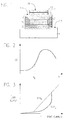
- FIG. 1 An exemplary embodiment of our invention using a vertical cavity surface emitting laser is depicted in a sectional view in FIG. 1.
- substrate 1 region 3 having a first conductivity type
- active region 5 regions 7 and 9 having a second conductivity type
- quantum well region 11 regions 7 and 9 having a second conductivity type
- region 13 having a region of first conductivity type.
- Region 11 has intrinsic conductivity and comprises one or more quantum wells.
- Regions 3, 7, 9, and 13 comprise mirrors which are depicted as interference mirrors.
- Region 3 comprises a first mirror.
- regions 3 and 7 have first and second conductivity types, respectively. The remaining portions may have conductivity of the same type or have intrinsic conductivity. Appropriate regions of different conductivity types will be readily selected by those skilled in the art. Regions 7, 9, 11, and 13 form a second, distributed mirror with controllable reflectivity.
- the active region typically comprises one or more quantum well regions which are interleaved with barrier layers, i.e., layers having a bandgap greater than the bandgap of the quantum well region. However, the use of bulk semiconductors is not precluded. There are first, second, and third electrical contacts 15, 17, and 19, to regions 3 and 7, and to layer 13, respectively.
- Isolation region 21 restricts the area of the current flow through the active region to the area generally under region 13.
- Isolation region 21 can be formed by, e.g., deep ion implantation. Other forms of current and optical confinement are contemplated.
- the portions of regions 3 and 7 having first and second conductivity types form means for injecting carriers into the active region.
- the first interference mirror comprises, and the second interference mirror further comprises, a plurality of interleaved first and second semiconductor layers with each layer having characteristics such that it is typically a quarter wavelength thick at the medium wavelength of interest thereby forming an interference mirror.
- the individual layers of the active region and the interference mirrors are not individually depicted as those skilled in the art know the structure of these elements.
- the substrate is semi-insulating GaAs; regions 3, 7, 9, and 13 comprise alternating layers of AlAs and AlGaAs with properties as described in the previous paragraph.
- the active region comprises between 1 and 4 GaAs quantum wells interleaved with AlGaAs barrier layers.
- Quantum well region 11 is optically coupled to region 7; i.e., the absorption due to the quantum wells is within the distributed mirror.
- Region 11 has at least one quantum well of GaAs, separated by barrier layers of AlGaAs, and positioned in an intrinsic conductivity region of AlGaAs.
- Region 13 comprises interference mirror layers of, e.g., AlAs and AlGaAs, and has a first conductivity type.
- Those skilled in the art will readily select appropriate layer thicknesses and these parameters need not be described in detail.
- the use of other semiconductors is contemplated and appropriate choices will readily be made by those skilled in the art. For example, other Group III-IV semiconductors may be used.
- the intensity of the light emitted from the device can be vied by controlling the reflectivity of the mirror.
- An exemplary embodiment using the quantum-confined Stark effect will be described. This effect is now well known and understood by those skilled in the art; the effect is described in a chapter written by Miller, Chemla and Schmitt-Rink in Optical Nonlinearities and Instabilities in Semiconductors, pp. 339-347, Academic Press, 1988.
- the exciton absorption depends on the magnitude of the electric field in the quantum well.
- FIG. 2 plots the absorption coefficient of the quantum well region vertically versus the applied voltage horizontally for a wavelength longer than that of the zero field exciton.
- the voltage is between contacts 19 and 17, i.e., a reverse bias p-i-n junction, and that an increasing voltage corresponds to an increasing electric field and vice versa.
- Arbitrary units are used for purposes of exposition.
- the initial voltage is V b and it will be assumed that the laser is OFF at that voltage. As can be seen, the absorption coefficient can be vied a significant amount with a relatively small change in the voltage.
- a vertical cavity surface-emitting laser needs relatively large reflectivities in both mirror stacks for lasing; typically, mirror stack reflectivities should be 99 per cent or greater.
- the quantum well region should have minimal absorption when the laser is ON for efficient operation of the laser.
- the quantum well region is, as previously described, desirably incorporated into an intrinsic conductivity region which forms part of a reverse bias p-i-n structure.
- a small voltage change is needed to vary the reflectivity of the mirror.
- the magnitude of the current supplied through contacts 15 and 17 remain essentially constant as the laser is turned ON and OFF. This simplifies the design of the power supply (not shown) for the array and minimizes any problems that might otherwise arise due to the varying heat generated in the vertical cavity laser array, to the varying carrier density in the active region, and to the resulting index changes in the optical cavity.
- the optical spatial field distribution of the surface emitting laser and the position of the quantum well absorber are both engineering parameters. More or less absorption can be obtained by placing the absober near a node or antinode, respectively. More or less absorption can also be obtained by increasing or decreasing the reflectivity of region 7, thereby coupling relatively less or more of the quantum well absorption into the distributed mirror. Additionally, the design and number of the quantum wells can be varied from that described. Those skilled in the art will readily select appropriate parameters.
- the laser may be used in a self latching mode. After the laser is turned ON at some drive current, the intensity of the optical field may be sufficiently great in the quantum well absorber so that the quantum well absorber is bleached, i.e., saturated, even when the bias is returned to V b .
- the precise behavior will depend upon the absorption coefficient and the laser power as well as other parameters. In general terms, the explanation is as follows. Before lasing occurs at an appropriate laser drive current, the absorption in the quantum well region is high and the cavity Q is spoiled. The bias is now reduced to zero volts and the gain in the vertical cavity exceeds the loss and the laser turns ON. The high optical intensity saturates the absorber and the bias will likely have to be increased to, e.g., 2 V b , to turn the laser OFF as V b will no longer suffice.
- controllable mirror may use any voltage controllable effect.
- the light may be emitted through either the substrate or the top mirror.
- vertical is used to mean perpendicular to the major surfaces of the substrate.
- the means for rejecting can have first and second conductivity types on opposite sides of the active region, either along the axis formed by the first mirror, active region and second mirror, or along some other axis.
Abstract
Description
- This invention relates to the field of semiconductor lasers which have a mirror with controllable reflectivity for adjusting the lasing threshold and the intensity of the emitted radiation.
- Semiconductor lasers have found widespread use in modern technology as the light source of choice in, e.g., communications systems, compact disc players, etc. The typical semiconductor laser is a double heterostructure with a narrow bandgap, high refractive index layer surrounded on opposed major surfaces by wide bandgap, low refractive index layers. The low bandgap layer is termed the "active layer," and the bandgap and refractive index differences serve to confine both charge carriers and optical energy to the active layer or region. Opposite ends of the active layer have mirror facets which form the laser cavity. The cladding layers have opposite conductivity types and when current is passed through the structure, electrons and holes combine in the active layer to generate light.
- While perfectly adequate for many applications, the structure described has two drawbacks which are pertinent to this invention. First, the active layer has a longitudinal axis which runs parallel to the major surfaces of the structure and substrate and the light is emitted in a direction generally parallel to the longitudinal axis; i.e., the structure is an edge emitting device. However, for many purposes, it is desirable that light be emitted in a direction perpendicular to the substrate; i.e., that the device be a surface emitting device. For example, surface emitting devices can be fabricated in arrays with relative ease while edge emitting devices can not be so fabricated. Such arrays are potentially useful in such diverse applications as, for example, image processing, inter-chip communications, i.e., optical interconnects, etc. Second, the laser is typically turned ON and OFF by varying the current flow through the device. This requires a relatively large change in the current through the device which is undesirable.
- Several types of surface emitting lasers have been developed. One such laser of special promise is termed a "vertical cavity surface emitting laser." See, for example, Optical Engineering, 29, pp. 210-214, March 1990 for a description of this laser. Also, see Electronics Letters, 26, pp. 710-711, March 24, 1990. The laser described has an active region with one or more quantum well layers. The quantum well layers are interleaved with barrier layers. On opposite sides of the active region are mirror stacks which are formed by interleaved semiconductor layers having properties, such that each layer is typically a quarter wavelength thick at the wavelength (in the medium) of interest thereby forming the mirrors for the laser cavity. There are opposite conductivity type regions on opposite sides of the active region, and the laser is turned ON and OFF by varying the current through the active region. Variations, including dielectric and metal mirrors and metal contact, have been demonstrated.
- An array of lasers is fabricated by growing the desired layers on a substrate and then patterning the layers to form the array. Individual lasers may be separately contacted with appropriate contacts. Laser densities in excess of a million lasers per square centimeter can presently be obtained.
- However, a technique for turning the laser ON and OFF and for varying the intensity of the emitted radiation from a vertical cavity surface emitting laser which is easily monolithically integrated with the laser would be desirable.
- A laser comprising a vertical cavity surface emitting laser having an active region, first and second mirrors on opposite sides of said active region, at least one of said minors on one side of said active region having controllable reflectivity, and a means for injecting carriers into said active region. Means for injecting may comprise first and second regions having first and second conductivity types on opposite sides of said active region. In one embodiment, the active region comprises at least one quantum well with quantum well barrier layers matched in conductivity to the adjacent mirror regions.
- In a preferred embodiment, the mirror having controllable reflectivity comprises a region having voltage controlled optical properties. In one embodiment, the optical property is absorption. In a further preferred embodiment, the minor having controllable reflectivity further comprises at least one quantum well and a region having a first conductivity type on the side of the quantum well away from the active region. The quantum well is in an intrinsic conductivity region which is adjacent to the second conductivity type region of the means for injecting carriers into the active region. The laser thus has regions of first, second, intrinsic, and first conductivity types. In this embodiment, the mirror uses the quantum-confined Stark effect to change the optical absorption of the mirror and thus control the reflectivity of the minor. The mirror may have its reflectivity controlled either optically or electrically.
-
- FIG. 1 is a sectional view of a laser according to this invention;
- FIG. 2 plots the absorption coefficient vertically versus the voltage horizontally for an exemplary quantum-confined Stark effect region useful in this invention; and,
- FIG. 3 plots the light output versus the drive current for two different reflectivity conditions produced by two voltage levels.
- For reasons of clarity, the elements depicted are not drawn to scale.
- An exemplary embodiment of our invention using a vertical cavity surface emitting laser is depicted in a sectional view in FIG. 1. As will be appreciated by those skilled in the art, some elements which are not essential to an understanding of the invention are either not depicted or described in detail. For example, only a single laser is depicted, although it will be readily appreciated that an array of lasers will typically be present. Depicted are substrate 1,
region 3 having a first conductivity type,active region 5, regions 7 and 9 having a second conductivity type,quantum well region 11, andregion 13 having a region of first conductivity type.Region 11 has intrinsic conductivity and comprises one or more quantum wells.Regions Region 3 comprises a first mirror. Only several layers are shown for reasons of clarity. At least parts ofregions 3 and 7 have first and second conductivity types, respectively. The remaining portions may have conductivity of the same type or have intrinsic conductivity. Appropriate regions of different conductivity types will be readily selected by those skilled in the art.Regions electrical contacts regions 3 and 7, and tolayer 13, respectively. Contact 15 may be physically made to substrate 1 if the substrate is conducting and not semi-insulating.Isolation region 21 restricts the area of the current flow through the active region to the area generally underregion 13.Isolation region 21 can be formed by, e.g., deep ion implantation. Other forms of current and optical confinement are contemplated. The portions ofregions 3 and 7 having first and second conductivity types form means for injecting carriers into the active region. The first interference mirror comprises, and the second interference mirror further comprises, a plurality of interleaved first and second semiconductor layers with each layer having characteristics such that it is typically a quarter wavelength thick at the medium wavelength of interest thereby forming an interference mirror. The individual layers of the active region and the interference mirrors are not individually depicted as those skilled in the art know the structure of these elements. - In an exemplary embodiment, the substrate is semi-insulating GaAs;
regions regions 3 and 7 which are doped with Si and Be to give the regions first and second conductivity types, respectively.Quantum well region 11 is optically coupled to region 7; i.e., the absorption due to the quantum wells is within the distributed mirror.Region 11 has at least one quantum well of GaAs, separated by barrier layers of AlGaAs, and positioned in an intrinsic conductivity region of AlGaAs.Region 13 comprises interference mirror layers of, e.g., AlAs and AlGaAs, and has a first conductivity type. Those skilled in the art will readily select appropriate layer thicknesses and these parameters need not be described in detail. The use of other semiconductors is contemplated and appropriate choices will readily be made by those skilled in the art. For example, other Group III-IV semiconductors may be used. - Conventional and well known epitaxial growth techniques, such as molecular beam epitaxy or metallo-organic chemical vapor deposition, may be used to grow the layers described. After the layers have been grown, conventional patterning techniques are then used to form the individual lasers in the array. Electrical contacts to the individual lasers are also fabricated. Those skilled in the art will readily select appropriate patterning and contacting techniques.
- The intensity of the light emitted from the device can be vied by controlling the reflectivity of the mirror. An exemplary embodiment using the quantum-confined Stark effect will be described. This effect is now well known and understood by those skilled in the art; the effect is described in a chapter written by Miller, Chemla and Schmitt-Rink in Optical Nonlinearities and Instabilities in Semiconductors, pp. 339-347, Academic Press, 1988. Basically, the exciton absorption depends on the magnitude of the electric field in the quantum well. FIG. 2 plots the absorption coefficient of the quantum well region vertically versus the applied voltage horizontally for a wavelength longer than that of the zero field exciton. It will be readily appreciated that the voltage is between
contacts - This property is used in our laser as follows. A vertical cavity surface-emitting laser needs relatively large reflectivities in both mirror stacks for lasing; typically, mirror stack reflectivities should be 99 per cent or greater. The quantum well region functions as a bias dependent mirror and, by appropriately varying the bias, the laser can be turned ON or OFF as the value of the absorption is shifted. For example, assume the laser is OFF at Vb with drive current I₁. Reducing the voltage to zero reduces the absorption and thereby restores the reflectivity of the mirror stack. The laser then turns ON, with light output appropriate for the low absorption, high reflectivity state. This is shown in FIG. 3 as V=Va. As will be readily appreciated, the quantum well region should have minimal absorption when the laser is ON for efficient operation of the laser. The quantum well region is, as previously described, desirably incorporated into an intrinsic conductivity region which forms part of a reverse bias p-i-n structure. A small voltage change is needed to vary the reflectivity of the mirror. However, the magnitude of the current supplied through
contacts - The optical spatial field distribution of the surface emitting laser and the position of the quantum well absorber are both engineering parameters. More or less absorption can be obtained by placing the absober near a node or antinode, respectively. More or less absorption can also be obtained by increasing or decreasing the reflectivity of region 7, thereby coupling relatively less or more of the quantum well absorption into the distributed mirror. Additionally, the design and number of the quantum wells can be varied from that described. Those skilled in the art will readily select appropriate parameters.
- The laser may be used in a self latching mode. After the laser is turned ON at some drive current, the intensity of the optical field may be sufficiently great in the quantum well absorber so that the quantum well absorber is bleached, i.e., saturated, even when the bias is returned to Vb. The precise behavior will depend upon the absorption coefficient and the laser power as well as other parameters. In general terms, the explanation is as follows. Before lasing occurs at an appropriate laser drive current, the absorption in the quantum well region is high and the cavity Q is spoiled. The bias is now reduced to zero volts and the gain in the vertical cavity exceeds the loss and the laser turns ON. The high optical intensity saturates the absorber and the bias will likely have to be increased to, e.g., 2 Vb, to turn the laser OFF as Vb will no longer suffice.
- Variations of the embodiment described are contemplated. For example, the controllable mirror may use any voltage controllable effect. The light may be emitted through either the substrate or the top mirror. It will also be understood that the term, "vertical," is used to mean perpendicular to the major surfaces of the substrate. The means for rejecting can have first and second conductivity types on opposite sides of the active region, either along the axis formed by the first mirror, active region and second mirror, or along some other axis.
Claims (8)
- A laser comprising a vertical cavity surface emitting laser having an active region (e.g. 5);
first (e.g. 3) and second (e.g. 7, 9, 11, 13) mirrors on opposite sides of said active region (e.g. 5), at least one of said mirrors having controllable reflectivity; and means for injecting carriers (e.g. 17, 15) into said active region (e.g. 5). - A laser as recited in claim 1 in which said means for injecting comprises first and second regions (e.g. 3, 7) having first and second conductivity types on opposite sides of said active region (e.g. 5).
- A laser as recited in claim 2 in which said mirror having controllable reflectivity further comprises at least one quantum well (e.g. 11) and a region having a first conductivity type (e.g. 13), said region of second conductivity type (e.g. 7) being between said regions of first conductivity types (e.g. 3, 13,).
- A laser as recited in claim 3 further comprising an intrinsic conductivity region (e.g. 11), said at least one quantum well (e.g. 11) being in said region.
- A laser as recited in claim 1 in which the reflectivity of said mirror (e.g. 7, 9, 11, 13) is controlled optically.
- A laser as recited in claim 1 in which the reflectivity of said mirror (e.g. 7, 9, 11, 13) is controlled electrically.
- A laser as recited in claim 2 in which at least one of said mirrors comprises an interference mirror.
- A laser as recited in claim 1 in which said active region (e.g. 5) comprises at least one quantum well.
Applications Claiming Priority (2)
| Application Number | Priority Date | Filing Date | Title |
|---|---|---|---|
| US07/548,033 US5056098A (en) | 1990-07-05 | 1990-07-05 | Vertical cavity laser with mirror having controllable reflectivity |
| US548033 | 1995-10-25 |
Publications (3)
| Publication Number | Publication Date |
|---|---|
| EP0465145A2 true EP0465145A2 (en) | 1992-01-08 |
| EP0465145A3 EP0465145A3 (en) | 1992-07-22 |
| EP0465145B1 EP0465145B1 (en) | 1995-09-20 |
Family
ID=24187135
Family Applications (1)
| Application Number | Title | Priority Date | Filing Date |
|---|---|---|---|
| EP91305859A Expired - Lifetime EP0465145B1 (en) | 1990-07-05 | 1991-06-28 | Vertical cavity laser with mirror having controllable reflectivity |
Country Status (4)
| Country | Link |
|---|---|
| US (1) | US5056098A (en) |
| EP (1) | EP0465145B1 (en) |
| JP (1) | JP2545165B2 (en) |
| DE (1) | DE69113141T2 (en) |
Cited By (2)
| Publication number | Priority date | Publication date | Assignee | Title |
|---|---|---|---|---|
| EP0618651A2 (en) * | 1993-03-31 | 1994-10-05 | Fujitsu Limited | Surface emitting laser provided with light modulator |
| FR2805902A1 (en) * | 2000-03-03 | 2001-09-07 | Centre Nat Rech Scient | Semiconductor opto-electronic device has three semiconductor layers and spacers with respective thicknesses and compositions selected such that transfer function can be electrically adjustable |
Families Citing this family (40)
| Publication number | Priority date | Publication date | Assignee | Title |
|---|---|---|---|---|
| JPH04107976A (en) * | 1990-08-28 | 1992-04-09 | Mitsubishi Electric Corp | Semiconductor laser device |
| US5365541A (en) * | 1992-01-29 | 1994-11-15 | Trw Inc. | Mirror with photonic band structure |
| US5245622A (en) * | 1992-05-07 | 1993-09-14 | Bandgap Technology Corporation | Vertical-cavity surface-emitting lasers with intra-cavity structures |
| US5574738A (en) * | 1995-06-07 | 1996-11-12 | Honeywell Inc. | Multi-gigahertz frequency-modulated vertical-cavity surface emitting laser |
| JPH0964334A (en) * | 1995-08-28 | 1997-03-07 | Toshiba Corp | Integrated element of light emitting element and external modulator |
| US5978401A (en) * | 1995-10-25 | 1999-11-02 | Honeywell Inc. | Monolithic vertical cavity surface emitting laser and resonant cavity photodetector transceiver |
| US5764674A (en) * | 1996-06-28 | 1998-06-09 | Honeywell Inc. | Current confinement for a vertical cavity surface emitting laser |
| US5774487A (en) * | 1996-10-16 | 1998-06-30 | Honeywell Inc. | Filamented multi-wavelength vertical-cavity surface emitting laser |
| US5757837A (en) * | 1996-10-16 | 1998-05-26 | The Regents Of The University Of California | Intracavity quantum well photodetector integrated within a vertical-cavity surface-emitting laser and method of operating same |
| US6064683A (en) * | 1997-12-12 | 2000-05-16 | Honeywell Inc. | Bandgap isolated light emitter |
| US6341138B1 (en) | 1999-06-16 | 2002-01-22 | Gore Enterprise Holdings, Inc. | Constant temperature performance laser |
| US6990135B2 (en) * | 2002-10-28 | 2006-01-24 | Finisar Corporation | Distributed bragg reflector for optoelectronic device |
| US6905900B1 (en) | 2000-11-28 | 2005-06-14 | Finisar Corporation | Versatile method and system for single mode VCSELs |
| US7065124B2 (en) | 2000-11-28 | 2006-06-20 | Finlsar Corporation | Electron affinity engineered VCSELs |
| US6836501B2 (en) * | 2000-12-29 | 2004-12-28 | Finisar Corporation | Resonant reflector for increased wavelength and polarization control |
| TWI227799B (en) * | 2000-12-29 | 2005-02-11 | Honeywell Int Inc | Resonant reflector for increased wavelength and polarization control |
| US6782027B2 (en) | 2000-12-29 | 2004-08-24 | Finisar Corporation | Resonant reflector for use with optoelectronic devices |
| US6727520B2 (en) * | 2000-12-29 | 2004-04-27 | Honeywell International Inc. | Spatially modulated reflector for an optoelectronic device |
| DE10102458A1 (en) * | 2001-01-15 | 2002-07-25 | Infineon Technologies Ag | Laser diode for scanning media has fading absorber means for irradiating a vertical resonator and absorber material integrated into a sequence of layers. |
| US6606199B2 (en) | 2001-10-10 | 2003-08-12 | Honeywell International Inc. | Graded thickness optical element and method of manufacture therefor |
| US6816526B2 (en) * | 2001-12-28 | 2004-11-09 | Finisar Corporation | Gain guide implant in oxide vertical cavity surface emitting laser |
| US6965626B2 (en) | 2002-09-03 | 2005-11-15 | Finisar Corporation | Single mode VCSEL |
| US6813293B2 (en) | 2002-11-21 | 2004-11-02 | Finisar Corporation | Long wavelength VCSEL with tunnel junction, and implant |
| US7298942B2 (en) | 2003-06-06 | 2007-11-20 | Finisar Corporation | Pluggable optical optic system having a lens fiber stop |
| US7433381B2 (en) | 2003-06-25 | 2008-10-07 | Finisar Corporation | InP based long wavelength VCSEL |
| US7054345B2 (en) | 2003-06-27 | 2006-05-30 | Finisar Corporation | Enhanced lateral oxidation |
| US7075962B2 (en) | 2003-06-27 | 2006-07-11 | Finisar Corporation | VCSEL having thermal management |
| US7277461B2 (en) | 2003-06-27 | 2007-10-02 | Finisar Corporation | Dielectric VCSEL gain guide |
| US6961489B2 (en) | 2003-06-30 | 2005-11-01 | Finisar Corporation | High speed optical system |
| US7149383B2 (en) | 2003-06-30 | 2006-12-12 | Finisar Corporation | Optical system with reduced back reflection |
| US7210857B2 (en) | 2003-07-16 | 2007-05-01 | Finisar Corporation | Optical coupling system |
| US6887801B2 (en) | 2003-07-18 | 2005-05-03 | Finisar Corporation | Edge bead control method and apparatus |
| US7031363B2 (en) | 2003-10-29 | 2006-04-18 | Finisar Corporation | Long wavelength VCSEL device processing |
| US7829912B2 (en) * | 2006-07-31 | 2010-11-09 | Finisar Corporation | Efficient carrier injection in a semiconductor device |
| US7596165B2 (en) * | 2004-08-31 | 2009-09-29 | Finisar Corporation | Distributed Bragg Reflector for optoelectronic device |
| US7920612B2 (en) * | 2004-08-31 | 2011-04-05 | Finisar Corporation | Light emitting semiconductor device having an electrical confinement barrier near the active region |
| US8031752B1 (en) | 2007-04-16 | 2011-10-04 | Finisar Corporation | VCSEL optimized for high speed data |
| EP2525450B1 (en) | 2011-05-17 | 2017-10-04 | Danmarks Tekniske Universitet | Reflectivity-modulated grating-mirror |
| DK2729997T3 (en) | 2011-07-04 | 2016-01-25 | Univ Danmarks Tekniske | Laser devices |
| US9557556B2 (en) | 2013-03-18 | 2017-01-31 | Si-Ware Systems | Integrated apertured micromirror and applications thereof |
Citations (6)
| Publication number | Priority date | Publication date | Assignee | Title |
|---|---|---|---|---|
| DE1206526B (en) * | 1961-08-18 | 1965-12-09 | Standard Elektrik Lorenz Ag | Modulable optical transmitter |
| JPS59115583A (en) * | 1982-12-22 | 1984-07-04 | Sanyo Electric Co Ltd | Semiconductor laser |
| JPS6032381A (en) * | 1983-08-01 | 1985-02-19 | Matsushita Electric Ind Co Ltd | Surface light emitting semiconductor laser device |
| JPS60154693A (en) * | 1984-01-25 | 1985-08-14 | Fujitsu Ltd | Semiconductor light emitting device |
| JPS6179280A (en) * | 1984-09-27 | 1986-04-22 | Agency Of Ind Science & Technol | Surface light-emitting type semiconductor laser device and manufacture thereof |
| JPH0311689A (en) * | 1989-06-08 | 1991-01-18 | Fujikura Ltd | Surface light-emitting type wavelength-control dbr laser |
Family Cites Families (5)
| Publication number | Priority date | Publication date | Assignee | Title |
|---|---|---|---|---|
| JPH0793473B2 (en) * | 1987-10-06 | 1995-10-09 | 古河電気工業株式会社 | Optical semiconductor device |
| JPS6446996A (en) * | 1988-08-03 | 1989-02-21 | Agency Ind Science Techn | Method for realizing optical bistable function and optical bistable function element |
| US4943970A (en) * | 1988-10-24 | 1990-07-24 | General Dynamics Corporation, Electronics Division | Surface emitting laser |
| US4873696A (en) * | 1988-10-31 | 1989-10-10 | The Regents Of The University Of California | Surface-emitting lasers with periodic gain and a parallel driven nipi structure |
| US4949350A (en) * | 1989-07-17 | 1990-08-14 | Bell Communications Research, Inc. | Surface emitting semiconductor laser |
-
1990
- 1990-07-05 US US07/548,033 patent/US5056098A/en not_active Expired - Lifetime
-
1991
- 1991-06-28 DE DE69113141T patent/DE69113141T2/en not_active Expired - Fee Related
- 1991-06-28 EP EP91305859A patent/EP0465145B1/en not_active Expired - Lifetime
- 1991-07-05 JP JP3191251A patent/JP2545165B2/en not_active Expired - Fee Related
Patent Citations (6)
| Publication number | Priority date | Publication date | Assignee | Title |
|---|---|---|---|---|
| DE1206526B (en) * | 1961-08-18 | 1965-12-09 | Standard Elektrik Lorenz Ag | Modulable optical transmitter |
| JPS59115583A (en) * | 1982-12-22 | 1984-07-04 | Sanyo Electric Co Ltd | Semiconductor laser |
| JPS6032381A (en) * | 1983-08-01 | 1985-02-19 | Matsushita Electric Ind Co Ltd | Surface light emitting semiconductor laser device |
| JPS60154693A (en) * | 1984-01-25 | 1985-08-14 | Fujitsu Ltd | Semiconductor light emitting device |
| JPS6179280A (en) * | 1984-09-27 | 1986-04-22 | Agency Of Ind Science & Technol | Surface light-emitting type semiconductor laser device and manufacture thereof |
| JPH0311689A (en) * | 1989-06-08 | 1991-01-18 | Fujikura Ltd | Surface light-emitting type wavelength-control dbr laser |
Non-Patent Citations (7)
| Title |
|---|
| APPLIED PHYSICS LETTERS. vol. 50, no. 18, 4 May 1987, NEW YORK US pages 1225 - 1227; P.L. GOURLEY ET AL.: 'Visible, room-temperature, surface-emitting laser using an epitaxial Fabry-Perot resonator with AlGaAs/AlAs quarter-wave high reflectors and AlGaAs/GaAs multiple quantum wells' * |
| APPLIED PHYSICS LETTERS. vol. 51, no. 11, 14 September 1987, NEW YORK US pages 826 - 827; K. TAI ET AL.: 'Chemical beam epitaxially grown InP/InGaAsP interference mirror for use near 1.55 mum wavelength' * |
| PATENT ABSTRACTS OF JAPAN vol. 10, no. 251 (E-432)28 August 1986 & JP-A-61 079 280 ( AGENCY OF IND. SCIENCE & TECHNOL. ) * |
| PATENT ABSTRACTS OF JAPAN vol. 15, no. 125 (E-1050)27 March 1991 & JP-A-3 011 689 ( FUJIKURA LTD. ) * |
| PATENT ABSTRACTS OF JAPAN vol. 8, no. 235 (E-275)27 October 1984 & JP-A-59 115 583 ( SANYO DENKI K.K. ) * |
| PATENT ABSTRACTS OF JAPAN vol. 9, no. 154 (E-325)28 June 1985 & JP-A-60 032 381 ( MATSUSHITA DENKI SANGYO K.K. ) * |
| PATENT ABSTRACTS OF JAPAN vol. 9, no. 321 (E-367)17 December 1985 & JP-A-60 154 693 ( FUJITSU K.K. ) * |
Cited By (6)
| Publication number | Priority date | Publication date | Assignee | Title |
|---|---|---|---|---|
| EP0618651A2 (en) * | 1993-03-31 | 1994-10-05 | Fujitsu Limited | Surface emitting laser provided with light modulator |
| EP0618651A3 (en) * | 1993-03-31 | 1994-12-21 | Fujitsu Ltd | Surface emitting laser provided with light modulator. |
| US5408486A (en) * | 1993-03-31 | 1995-04-18 | Fujitsu Limited | Surface emitting laser provided with light modulator |
| FR2805902A1 (en) * | 2000-03-03 | 2001-09-07 | Centre Nat Rech Scient | Semiconductor opto-electronic device has three semiconductor layers and spacers with respective thicknesses and compositions selected such that transfer function can be electrically adjustable |
| WO2001065301A1 (en) * | 2000-03-03 | 2001-09-07 | Centre National De La Recherche Scientifique (Cnrs) | Semiconductor optoelectronic device with electrically adjustable transfer function |
| CN100442101C (en) * | 2000-03-03 | 2008-12-10 | 国家科研中心 | Semiconductor optoelectronic device with electrically adjustable transfer function |
Also Published As
| Publication number | Publication date |
|---|---|
| JP2545165B2 (en) | 1996-10-16 |
| JPH04233293A (en) | 1992-08-21 |
| DE69113141T2 (en) | 1996-05-09 |
| DE69113141D1 (en) | 1995-10-26 |
| EP0465145A3 (en) | 1992-07-22 |
| EP0465145B1 (en) | 1995-09-20 |
| US5056098A (en) | 1991-10-08 |
Similar Documents
| Publication | Publication Date | Title |
|---|---|---|
| US5056098A (en) | Vertical cavity laser with mirror having controllable reflectivity | |
| US5412680A (en) | Linear polarization of semiconductor laser | |
| EP0830718B1 (en) | Multi-gigahertz frequency-modulated vertical-cavity surface emitting laser | |
| US5212706A (en) | Laser diode assembly with tunnel junctions and providing multiple beams | |
| US6040590A (en) | Semiconductor device with electrostatic control | |
| US5287376A (en) | Independently addressable semiconductor diode lasers with integral lowloss passive waveguides | |
| US4594718A (en) | Combination index/gain guided semiconductor lasers | |
| US4829357A (en) | PNPN thyristor | |
| EP0337688B1 (en) | Phase-locked array of semiconductor lasers using closely spaced antiguides | |
| EP1048081B1 (en) | Bandgap isolated light emitter | |
| US4845725A (en) | Window laser with high power reduced divergence output | |
| WO1996032766A1 (en) | Long wavelength, vertical cavity surface emitting laser with vertically integrated optical pump | |
| EP0397691B1 (en) | Current injection laser | |
| US6031859A (en) | Mode-locked semiconductor laser | |
| US4982408A (en) | Variable oscillation wavelength semiconduction laser device | |
| EP0935319B1 (en) | Surface-emitting laser device | |
| EP0493104B1 (en) | Laser arrays | |
| US4719632A (en) | Single contact tailored gain chirped arrays of diode lasers for supermode control with single-lobed farfield patterns | |
| US4965806A (en) | Semiconductor laser devices having lateral refractive index tailoring | |
| JPH05283809A (en) | Improved array and method of activating modulated solid-state laser array having reduced thermal crosstalk | |
| US6795470B1 (en) | Semiconductor laser light source with photocurrent feedback control for single mode operation | |
| EP0284684B1 (en) | Inverted channel substrate planar semiconductor laser | |
| US6560265B2 (en) | Method and apparatus for polarizing light in a VCSEL | |
| US4380075A (en) | Mode stable injection laser diode | |
| Ide et al. | Continuous output beam steering in vertical-cavity surface-emitting lasers with two p-type electrodes by controlling injection current profile |
Legal Events
| Date | Code | Title | Description |
|---|---|---|---|
| PUAI | Public reference made under article 153(3) epc to a published international application that has entered the european phase |
Free format text: ORIGINAL CODE: 0009012 |
|
| AK | Designated contracting states |
Kind code of ref document: A2 Designated state(s): DE FR GB |
|
| PUAL | Search report despatched |
Free format text: ORIGINAL CODE: 0009013 |
|
| AK | Designated contracting states |
Kind code of ref document: A3 Designated state(s): DE FR GB |
|
| 17P | Request for examination filed |
Effective date: 19930107 |
|
| 17Q | First examination report despatched |
Effective date: 19930608 |
|
| RAP3 | Party data changed (applicant data changed or rights of an application transferred) |
Owner name: AT&T CORP. |
|
| GRAA | (expected) grant |
Free format text: ORIGINAL CODE: 0009210 |
|
| AK | Designated contracting states |
Kind code of ref document: B1 Designated state(s): DE FR GB |
|
| REF | Corresponds to: |
Ref document number: 69113141 Country of ref document: DE Date of ref document: 19951026 |
|
| ET | Fr: translation filed | ||
| PLBE | No opposition filed within time limit |
Free format text: ORIGINAL CODE: 0009261 |
|
| STAA | Information on the status of an ep patent application or granted ep patent |
Free format text: STATUS: NO OPPOSITION FILED WITHIN TIME LIMIT |
|
| 26N | No opposition filed | ||
| PGFP | Annual fee paid to national office [announced via postgrant information from national office to epo] |
Ref country code: GB Payment date: 20010525 Year of fee payment: 11 Ref country code: FR Payment date: 20010525 Year of fee payment: 11 |
|
| PGFP | Annual fee paid to national office [announced via postgrant information from national office to epo] |
Ref country code: DE Payment date: 20010629 Year of fee payment: 11 |
|
| REG | Reference to a national code |
Ref country code: GB Ref legal event code: IF02 |
|
| PG25 | Lapsed in a contracting state [announced via postgrant information from national office to epo] |
Ref country code: GB Free format text: LAPSE BECAUSE OF NON-PAYMENT OF DUE FEES Effective date: 20020628 |
|
| PG25 | Lapsed in a contracting state [announced via postgrant information from national office to epo] |
Ref country code: DE Free format text: LAPSE BECAUSE OF NON-PAYMENT OF DUE FEES Effective date: 20030101 |
|
| PG25 | Lapsed in a contracting state [announced via postgrant information from national office to epo] |
Ref country code: FR Free format text: LAPSE BECAUSE OF NON-PAYMENT OF DUE FEES Effective date: 20030228 |
|
| REG | Reference to a national code |
Ref country code: FR Ref legal event code: ST |