EP0460873A1 - Apparatus for displaying an image - Google Patents
Apparatus for displaying an image Download PDFInfo
- Publication number
- EP0460873A1 EP0460873A1 EP91304918A EP91304918A EP0460873A1 EP 0460873 A1 EP0460873 A1 EP 0460873A1 EP 91304918 A EP91304918 A EP 91304918A EP 91304918 A EP91304918 A EP 91304918A EP 0460873 A1 EP0460873 A1 EP 0460873A1
- Authority
- EP
- European Patent Office
- Prior art keywords
- image
- apparent
- retroreflector
- retroreflectors
- original
- Prior art date
- Legal status (The legal status is an assumption and is not a legal conclusion. Google has not performed a legal analysis and makes no representation as to the accuracy of the status listed.)
- Granted
Links
Images


Classifications
-
- G—PHYSICS
- G02—OPTICS
- G02B—OPTICAL ELEMENTS, SYSTEMS OR APPARATUS
- G02B30/00—Optical systems or apparatus for producing three-dimensional [3D] effects, e.g. stereoscopic images
- G02B30/50—Optical systems or apparatus for producing three-dimensional [3D] effects, e.g. stereoscopic images the image being built up from image elements distributed over a 3D volume, e.g. voxels
- G02B30/56—Optical systems or apparatus for producing three-dimensional [3D] effects, e.g. stereoscopic images the image being built up from image elements distributed over a 3D volume, e.g. voxels by projecting aerial or floating images
Definitions
- the present invention relates to apparatus for displaying an image and has particular, though not exclusive, relevance to apparatus for displaying a television screen image.
- apparatus for displaying an apparent three dimensional image of an object or original image, the apparatus comprising; at least one array of retroreflectors and at least one beamsplitter; arranged to produce from the object or original image, a real image suspended in space for viewing as the apparent three dimensional image.
- a real image in space is formed without the use of large and expensive lenses or curved mirrors with their associated distortions and aberrations, without the same degree of limitation on the viewing angles imposed in practice by the numerical apertures of such lenses or curved mirrors and without the need for a projection screen to scatter or diffuse the real image in order to make it visible.
- the retroreflector is in the form of an array of corner-cubes formed as protrusions or depressions on a major surface of a sheet of suitable material, such as a plastics material.
- Corner-cubes formed as protrusions on the surface of a transparent material may optionally be coated with a reflective metal, such as aluminium. This allows for enhanced resolution of the image suspended in space.
- an arrangement with the corner-cubes formed as protrusions on the surface of a transparent material may simply make use of total internal reflection within the solid transparent material.
- corner-cubes are formed as depressions on the surface of the sheet, they should be made reflective by coating with a reflective metal such as aluminium.
- This construction has the advantage that undesirable specular reflections from the front surface of the sheet are avoided and that any beam spreading of a retroflected ray, due to manufacturing tolerances in making the corner-cube array, is not exaggerated by refraction when emerging from the transparent material.
- the array of retroreflectors may be in the form of a sheet of the glass bead type and may include such beads as have a graded index of refraction such as are present in Luneberg lenses.
- a graded index of refraction such as are present in Luneberg lenses.
- the flatness cues in the original image are sufficiently weakened that perception of the depth cues recorded pictorially in the real image dominates and 3-D perception is achieved. Solid objects may also pass through the real image without hindrance.
- the beam splitter is a partially transparent semi-reflective mirror. This allows the image of the original scene to be split into two channels, each of which may be retroreflected then recombined to produce the real image in space.
- the invention also provides for the formation of an apparent three dimensional real image suspended in space from a conventional television receiver without the need for any adjustment or modification of the image displayed on the television screen except, possibly, for increasing its brightness.
- any suitable two dimensional scene may be employed such as video or computer-generated image.
- a method for displaying an apparent three dimensional image of an object or original object or image comprising; projecting light beams from the original image via at least one beam splitter so as to strike at least one retroreflector array and reforming retroreflected light beams thereby to produce a real image suspended in space for viewing as the apparent three dimensional image.
- the invention is based on the perception of depth by humans based on the assimilation of depth cues perceived in the original scene.
- pictorial depth cues are: perspective, foreshortening, interposition, accommodation, motion parallax, and kinetic interposition. Those skilled in the art will appreciate that many more depth cues exist, and the above are given by way of example only.
- pictorial depth cues are inherent within any representation or picture of a scene, in principle they can be used in order to create a perception of depth within that picture.
- humans perceive, for example, a television screen image as being flat or two dimensional because either there are too many flatness cues, (for example, stereoscopic disparity, convergence, accommodation and framing effects) present in the image or that the number and strength of depth cues is too small.
- the apparatus of the present invention tends to weaken flatness cues sufficiently for the human eye/brain combination to utilise the pictorial depth cues and to perceive depth within the image formed.
- This weakening of the flatness cues derives from a number of contributory factors, for example, the absence of reflections or scattering from the real image as it is suspended in space, its detachment from any surrounding frame and its unusual occurrence suspended in front of the retroreflectors or superimposed on the real world beyond. This is achieved by the use of retroreflectors.
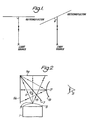
- retroreflectors The principles of retroreflectors are shown diagrammatically in Figure 1. It can be seen that light incident upon a retroreflector is substantially reflected back along its original path, whatever the angle of incidence (with limits defined by the type of retroreflector employed).
- the apparatus includes a conventional television set 1 arranged to lie so that its screen 3 is in a horizontal plane. Directly above the screen 3 and also in a horizontal plane is positioned a retroreflector 5a. Orthogonal to this retroreflector 5a and in a vertical plane there is arranged a further retroreflector 5b.
- the type of retroreflector chosen in this apparatus is of the corner-cube type such as is manufactured by the Reflexite Inc. company.
- a beam splitter Positioned between and at 45° to both retroreflectors 5a, 5b, is a beam splitter in the form of a partially transparent semi-reflective mirror 7.
- a television screen image is simply an array of such pixels, and as such a projected image of the whole television screen image may be viewed by an observer 21, the image of the television screen 3 appearing suspended in space at 19. Because many depth cues were present in the original image, they are also present in the real image suspended in space. However, because this real image is suspended in space, it has the appearance of viewing a scene through a window, and the flatness cues become weakened and allow the observer to use the image depth cues to create an effect of three dimensional viewing.
- Retroreflective surfaces as opposed to the large mirrors or lenses described in the prior art, a large numerical aperture is obtained which allows a wide viewing angle, and the high costs of large lenses and curved mirrors and their associated aberrations and distortions are avoided.
- Retroreflective sheets are available commercially in large sizes and at modest cost. Their positioning and orientations are not critical matters, in strict contrast to the use of lenses or curved mirrors which may distort the image produced if they are not accurately aligned and oriented.
- FIG. 4 With reference now also to Figure 4, it will be seen how an increased viewing angle is obtained.
- the apparatus of Figure 4 is similar to that of Figure 2, but with the inclusion of two plane mirrors 23a, 23b.
- the mirrors 23a, 23b, flank both retroreflectors 5a, 5b and the beamsplitter 7.
- the mirrors 23a, 23b are arranged such that they fit against both retroreflectors 5a, 5b and beamsplitter 7.
- each retroreflector 5a, 5b is necessarily in a direct optical line with the pixel 9 and beamsplitter 7, i.e. light from pixel 9 emitted at an elevated angle to the plane of the paper such that it passed through the beamsplitter 7 but did not strike either retroreflector 5a, 5b would not then form an apparent 3-D image.
- mirrors 23a, 23b need not be orthogonal to each other but may be angled and still allow an increased viewing angle.
- retroreflective surfaces Whilst in the example given hereinbefore, two retroreflective surfaces have been used, it will be apparent to those skilled in the art that any number or arrangement of retroreflectors will enable the successful working of the invention such as a retroreflective surface formed on the inside surface of an apertured sphere. Indeed, if one of the above mentioned retroreflectors, 5a or 5b is removed from the system, then a viewable image 19 will continue to be produced, but will be reduced in brightness by approximately half. Also, by removing one of the retroreflectors in the above example, it is possible to combine another image, real or virtual, with the apparent 3-D image 19, thus enabling the 3-D image to be overlaid over a background or foreground scene.
- An increase in brightness of the image 19 may be achieved by replacing the semi-reflective mirror 7 with a polarisation splitting layer or a circularly dichroic beam splitter such as one or more layers of circularly dichroic cholesteric or smectic liquid crystals or liquid crystal polymers and optionally, if required, quarter wave retarders placed in front of the retroreflective walls. Transmission or reflection of right-hand circularly polarised or left-hand circularly polarised light respectively by the layer is achieved, the light being reversed in polarisation upon being retroreflected (through the quarter wave retarder, if required,) and then respectively reflected and transmitted so that it recombines to give an unpolarised image having greater brightness than if the semi-reflective mirror 7 had been used.
- a polarisation splitting layer or a circularly dichroic beam splitter such as one or more layers of circularly dichroic cholesteric or smectic liquid crystals or liquid crystal polymers and optionally, if required, quarter wave retarders placed in front of the retro
- an apparent 3-D image suspended in space may be formed by an alternative arrangement to those detailed herebefore and which employs the properties of such polarisation splitter.
- Screen 3 is overlaid by a circular polariser 25 such that light from a pixel 9 having passed through polariser 25 is circular polarised in one sense, say, right hand circular polarised.
- the divergent right hand circularly polarised light then passes through a half-silvered retroreflector 27 and on to strike a circularly dichroic beamsplitter in the form of a cholesteric liquid crystal layer 29.
- Layer 29 has the optical property of transmitting light polarised in one circular sense, say left, and reflecting light of the other sense, right.
- the right circularly polarised light which strikes layer 29 will be reflected as a divergent beam towards the half-silvered retroreflector 27.
- retroreflector 27 On striking retroreflector 27 a portion of the light will be reflected back along its original path but (as will be apparent to those skilled in the art). Consequently, the sense of circular polarisation of the retroreflected light will have changed from right to left.
- the now left hand circularly polarised light impinges on layer 29 it will be transmitted and so from an apparent 3-D image for viewing at 21.
- the sheets of retroreflectors may be made very large and used to cover the walls and ceiling of a room in order to bring the real image of a movie or video recording of a life-size artiste out into the room for perception as three dimensional, this image may then be approached and even walked through, or viewed through a lens, e.g. a magnifying glass.
- the invention may equally well be employed to produce a 3-D image of a 3-D object, for example public display of precious jewellery in a shop window, with the real image brought through the glass and into the street for prospective customers to examine but not remove.
- Another example where the invention may be adopted is to create a real image, suspended in space, of one or more real lamps or light sources. It should be noted that a three dimensional object is turned inside out in the real image, thus a face produces a real image resembling a hollow mask.
- a true apparent 3-D image may be created by having two of the described embodiments arranged in a "back-to-back" format, that is such that the output (apparent 3-D image) of one becomes the input (object) for the other.
- retroreflector may be incorporated into the present invention, such as the glass bead type as manufactured by the 3M company under the trade mark "Scotchlite".
- the original object or image to be displayed is not limited to the examples given hereinbefore.
- Other suitable objects are computer generated pictures, visual display units, movie or cine pictures on a screen or a slide projection.
- the invention described hereinbefore provides an apparatus and method to produce an apparent 3-D image of an original scene based on the perception of depth cues present in the original scene, and by employing retroreflectors.
Abstract
Description
- The present invention relates to apparatus for displaying an image and has particular, though not exclusive, relevance to apparatus for displaying a television screen image.
- Methods of image display in order to produce stereoscopic or apparent three dimensional (3-D) displays are well known.
- One method generally requires the use of visual aids to separate stereoscopically disparate channels so that each image reaches appropriate eyes of a viewer. Such a method is described in U.K. Patent Application number GB 1523436 A. This disloses a system displaying two slightly differing images framed sequentially onto a single cathode ray tube. The images are formed in conjunction with a liquid crystal polarisation switch and viewed with polarising spectacles.
- However, not only can the use of visual aids such as the above mentioned spectacles be uncomfortable for the viewer, but the requirement for disparate images to be viewed by the appropriate eyes means that this type of method is not compatible with existing photographic or television images, and the like which are all based on the provision of a single two-dimensional (2-D) picture. This latter restriction also applies to the various known methods of producing stereoscopic or panoramic 3-D dimensional images using slit masks or lenticular screens and also to so called "cubic" 3-D image displays which cause light to be emitted from various points within a 'cubic' volume, for example, by reflecting a cathode ray tube in a vibrating mirror so that its image moves to describe the volume. None of the above methods is therefore retro-compatible with existing practices of television and photography which conventionally produce a flat, 2-D image.
- One other imaging method tends to use large lenses or mirrors to form real or virtual images of a single picture. This technique is known as "vue d'optique", a term well known in this art. One example of such a technique is described in U.K. Patent number GB 2062281 B. In this Patent is described the use of a large tilted Fresnel lens to form a real image of a single picture on a bell-shaped or saddle-shaped imaging surface. The formed image is distorted due to its formation on a tilted or curved surface, and the angle through which the image may be viewed is limited due to the finite numerical aperture of the mirror or lens, and to parallax between the image created and the edges of the mirror or lens.
- It is an object of the present invention to provide apparatus to produce a real image suspended in space for direct viewing and derived from an original image such as a two dimensional scene, or from an object, for perception as three dimensional. This is achieved by reducing the depth cues present in the original image which contribute to its perception as being flat or two dimensional, for example, stereoscopic binocular disparity, convergence, accommodation and motion parallax.
- It is a further object of the present invention to provide a method of producing a real image in space, derived from an object or original image such as a two dimensional scene, for perception as three dimensional.
- According to a first aspect of the present invention there is provided apparatus for displaying an apparent three dimensional image of an object or original image, the apparatus comprising; at least one array of retroreflectors and at least one beamsplitter; arranged to produce from the object or original image, a real image suspended in space for viewing as the apparent three dimensional image.
- Thus a real image in space is formed without the use of large and expensive lenses or curved mirrors with their associated distortions and aberrations, without the same degree of limitation on the viewing angles imposed in practice by the numerical apertures of such lenses or curved mirrors and without the need for a projection screen to scatter or diffuse the real image in order to make it visible.
- Preferably, the retroreflector is in the form of an array of corner-cubes formed as protrusions or depressions on a major surface of a sheet of suitable material, such as a plastics material.
- Corner-cubes formed as protrusions on the surface of a transparent material may optionally be coated with a reflective metal, such as aluminium. This allows for enhanced resolution of the image suspended in space.
- Alternatively, an arrangement with the corner-cubes formed as protrusions on the surface of a transparent material may simply make use of total internal reflection within the solid transparent material.
- If the corner-cubes are formed as depressions on the surface of the sheet, they should be made reflective by coating with a reflective metal such as aluminium. This construction has the advantage that undesirable specular reflections from the front surface of the sheet are avoided and that any beam spreading of a retroflected ray, due to manufacturing tolerances in making the corner-cube array, is not exaggerated by refraction when emerging from the transparent material.
- Alternatively, the array of retroreflectors may be in the form of a sheet of the glass bead type and may include such beads as have a graded index of refraction such as are present in Luneberg lenses. By the use of small diameter glass bead retroreflectors, retroreflective properties for a large range of angles of incidence, down to almost grazing incidence, are possible, and because this allows for a very large numerical aperture, large viewing angles are available.
- By the use of retroreflectors within the apparatus to create the real image suspended in space, the flatness cues in the original image are sufficiently weakened that perception of the depth cues recorded pictorially in the real image dominates and 3-D perception is achieved. Solid objects may also pass through the real image without hindrance.
- Preferably, the beam splitter is a partially transparent semi-reflective mirror. This allows the image of the original scene to be split into two channels, each of which may be retroreflected then recombined to produce the real image in space.
- Thus the invention also provides for the formation of an apparent three dimensional real image suspended in space from a conventional television receiver without the need for any adjustment or modification of the image displayed on the television screen except, possibly, for increasing its brightness. Furthermore, any suitable two dimensional scene may be employed such as video or computer-generated image.
- According to a second aspect of the present invention there is provided a method for displaying an apparent three dimensional image of an object or original object or image, the method comprising; projecting light beams from the original image via at least one beam splitter so as to strike at least one retroreflector array and reforming retroreflected light beams thereby to produce a real image suspended in space for viewing as the apparent three dimensional image.
- The invention will now be described, by way of example only, with reference to the accompanying drawings of which:-
- Figure 1 illustrates, in schematic form, the optical property of a retroreflector utilised in the present invention and,
- Figure 2 shows schematically an optical arrangement of the present invention, and,
- Figure 3 shows schematically a further arrangement of the present invention,
- Figure 4 illustrates an exploded view of yet a further arrangement of the present invention, and;
- Figure 5 illustrates an alternative arrangement to that of Figure 4.
- The invention is based on the perception of depth by humans based on the assimilation of depth cues perceived in the original scene.
- Many depth cues exist, only two of which - stereo-disparity and convergence - fundamentally require the use of both eyes. All the other depth cues - and they are well known to those skilled in the art - can be perceived with one eye only. Thus many of these other depth cues are able to be captured by a video camera or on a photograph or the like and many can be generated by a computer or artist and displayed in a photograph, painting or the like.
- Examples of such pictorial depth cues are: perspective, foreshortening, interposition, accommodation, motion parallax, and kinetic interposition. Those skilled in the art will appreciate that many more depth cues exist, and the above are given by way of example only.
- Since some or many of these pictorial depth cues are inherent within any representation or picture of a scene, in principle they can be used in order to create a perception of depth within that picture. However, humans perceive, for example, a television screen image as being flat or two dimensional because either there are too many flatness cues, (for example, stereoscopic disparity, convergence, accommodation and framing effects) present in the image or that the number and strength of depth cues is too small. The apparatus of the present invention tends to weaken flatness cues sufficiently for the human eye/brain combination to utilise the pictorial depth cues and to perceive depth within the image formed. This weakening of the flatness cues derives from a number of contributory factors, for example, the absence of reflections or scattering from the real image as it is suspended in space, its detachment from any surrounding frame and its unusual occurrence suspended in front of the retroreflectors or superimposed on the real world beyond. This is achieved by the use of retroreflectors.
- The principles of retroreflectors are shown diagrammatically in Figure 1. It can be seen that light incident upon a retroreflector is substantially reflected back along its original path, whatever the angle of incidence (with limits defined by the type of retroreflector employed).
- By referring now to Figure 2, it will be seen that the present invention involves creating a real image suspended in space.
- In this preferred embodiment, the apparatus includes a conventional television set 1 arranged to lie so that its
screen 3 is in a horizontal plane. Directly above thescreen 3 and also in a horizontal plane is positioned aretroreflector 5a. Orthogonal to thisretroreflector 5a and in a vertical plane there is arranged afurther retroreflector 5b. - The type of retroreflector chosen in this apparatus is of the corner-cube type such as is manufactured by the Reflexite Inc. company.
- Positioned between and at 45° to both
retroreflectors semi-reflective mirror 7. - Considering now a
pixel 9 on thescreen 3. Light from thepixel 9 will be emitted in divergent rays and strike thesemi-reflective mirror 7. In Figure 2, three such rays only 11, 13 and 15 are shown for clarity. The light is then split by thesemi-reflective mirror 7 wherein some light is reflected toretroreflector 5b and some light is transmitted toretroreflector 5a. Bothretroreflectors semi-reflective mirror 7. These light rays are once more split by thesemi-reflective mirror 7, but because the rays have been retroreflected when diverging, they now become convergent and so combine or reform to come to afocus 17, and form a suspended real image of the pixel in space. - Whilst the example above refers to a
single pixel 9, a television screen image is simply an array of such pixels, and as such a projected image of the whole television screen image may be viewed by anobserver 21, the image of thetelevision screen 3 appearing suspended in space at 19. Because many depth cues were present in the original image, they are also present in the real image suspended in space. However, because this real image is suspended in space, it has the appearance of viewing a scene through a window, and the flatness cues become weakened and allow the observer to use the image depth cues to create an effect of three dimensional viewing. - Furthermore, by utilising retroreflective surfaces as opposed to the large mirrors or lenses described in the prior art, a large numerical aperture is obtained which allows a wide viewing angle, and the high costs of large lenses and curved mirrors and their associated aberrations and distortions are avoided. Retroreflective sheets are available commercially in large sizes and at modest cost. Their positioning and orientations are not critical matters, in strict contrast to the use of lenses or curved mirrors which may distort the image produced if they are not accurately aligned and oriented.
- With reference now also to Figure 4, it will be seen how an increased viewing angle is obtained. The apparatus of Figure 4 is similar to that of Figure 2, but with the inclusion of two
plane mirrors mirrors retroreflectors beamsplitter 7. Themirrors retroreflectors beamsplitter 7. - In Figure 2, in order for an apparent 3-D image to be formed, each
retroreflector pixel 9 andbeamsplitter 7, i.e. light frompixel 9 emitted at an elevated angle to the plane of the paper such that it passed through thebeamsplitter 7 but did not strike eitherretroreflector - The arrangement of Figure 4 obviates this problem because light reflected from either
mirror beamsplitter 7 orretroreflector 5a or 5d dependent upon whether the point at which the light strikes the mirror is before or after passing throughbeamsplitter 7. - It will be apparent that the
mirrors - It will be apparent to those skilled in the art, by consideration of simple optical geometry that the
mirrors - It has also been found that by shielding the television screen from the view of the observer 21 a more dramatic 3-D effect is observed for the real image suspended in space. By referring to Figure 3, it may be seen that this is achieved by covering the
screen 3 with a louvre-screen 23 or the like. This louvre screen allows light to pass through it but only over a limited range of angles. Thus near normal light may pass through to reach the retroreflectors and form the real image, whilst obliquely emitted light from the original image, namely thescreen 3, is absorbed and the original image cannot be seen directly. - Whilst in the example given hereinbefore, two retroreflective surfaces have been used, it will be apparent to those skilled in the art that any number or arrangement of retroreflectors will enable the successful working of the invention such as a retroreflective surface formed on the inside surface of an apertured sphere. Indeed, if one of the above mentioned retroreflectors, 5a or 5b is removed from the system, then a
viewable image 19 will continue to be produced, but will be reduced in brightness by approximately half. Also, by removing one of the retroreflectors in the above example, it is possible to combine another image, real or virtual, with the apparent 3-D image 19, thus enabling the 3-D image to be overlaid over a background or foreground scene. An increase in brightness of theimage 19 may be achieved by replacing thesemi-reflective mirror 7 with a polarisation splitting layer or a circularly dichroic beam splitter such as one or more layers of circularly dichroic cholesteric or smectic liquid crystals or liquid crystal polymers and optionally, if required, quarter wave retarders placed in front of the retroreflective walls. Transmission or reflection of right-hand circularly polarised or left-hand circularly polarised light respectively by the layer is achieved, the light being reversed in polarisation upon being retroreflected (through the quarter wave retarder, if required,) and then respectively reflected and transmitted so that it recombines to give an unpolarised image having greater brightness than if thesemi-reflective mirror 7 had been used. - With reference now to Figure 5, it will be seen that an apparent 3-D image suspended in space may be formed by an alternative arrangement to those detailed herebefore and which employs the properties of such polarisation splitter.
-
Screen 3 is overlaid by acircular polariser 25 such that light from apixel 9 having passed throughpolariser 25 is circular polarised in one sense, say, right hand circular polarised. The divergent right hand circularly polarised light then passes through a half-silvered retroreflector 27 and on to strike a circularly dichroic beamsplitter in the form of a cholestericliquid crystal layer 29.Layer 29 has the optical property of transmitting light polarised in one circular sense, say left, and reflecting light of the other sense, right. - Hence, the right circularly polarised light which strikes
layer 29 will be reflected as a divergent beam towards the half-silvered retroreflector 27. On striking retroreflector 27 a portion of the light will be reflected back along its original path but (as will be apparent to those skilled in the art). Consequently, the sense of circular polarisation of the retroreflected light will have changed from right to left. Thus when the now left hand circularly polarised light impinges onlayer 29 it will be transmitted and so from an apparent 3-D image for viewing at 21. - Similar embodiments are envisaged using a non-corner cube type retroreflector which separates orthogonal linearly polarised components of the incident light and may also, optionally if required, use quarter wave retarders.
- It will be appreciated that if the distance between the
screen 3 andbeamsplitter 7 is increased, a corresponding increase in the distance between thebeam splitter 7 and the suspendedimage 19 will ensue, in line with conventional optics. Theobserver 21 may interact with theimage 19 or even walk right through it. It is envisaged that this effect will be of value in advertising displays or special effects. Furthermore, the sheets of retroreflectors may be made very large and used to cover the walls and ceiling of a room in order to bring the real image of a movie or video recording of a life-size artiste out into the room for perception as three dimensional, this image may then be approached and even walked through, or viewed through a lens, e.g. a magnifying glass. - The invention may equally well be employed to produce a 3-D image of a 3-D object, for example public display of precious jewellery in a shop window, with the real image brought through the glass and into the street for prospective customers to examine but not remove. Another example where the invention may be adopted is to create a real image, suspended in space, of one or more real lamps or light sources. It should be noted that a three dimensional object is turned inside out in the real image, thus a face produces a real image resembling a hollow mask.
- Thus it will be apparent that a true apparent 3-D image may be created by having two of the described embodiments arranged in a "back-to-back" format, that is such that the output (apparent 3-D image) of one becomes the input (object) for the other.
- It will be appreciated that other types of retroreflector may be incorporated into the present invention, such as the glass bead type as manufactured by the 3M company under the trade mark "Scotchlite".
- Additionally, it is envisaged that other forms of retroreflector may equally well be employed within the present invention.
- It will be further appreciated that the original object or image to be displayed is not limited to the examples given hereinbefore. Other suitable objects are computer generated pictures, visual display units, movie or cine pictures on a screen or a slide projection.
- Thus the invention described hereinbefore provides an apparatus and method to produce an apparent 3-D image of an original scene based on the perception of depth cues present in the original scene, and by employing retroreflectors.
Claims (15)
- Apparatus for displaying an apparent three-dimensional image of an object or original image, the apparatus comprising; at least one array of retroreflectors and at least one beamsplitter, arranged to produce from the object or original image, a real image suspended in space for viewing as the apparent three-dimensional image.
- Apparatus according to claim 1 wherein the retroreflector is in the form of a material having an array of corner cubes formed as protrusions or depressions on a major surface of the material.
- Apparatus according to claim 1 wherein the array of retroreflectors is in the form of a sheet of beads or microlenses.
- Apparatus according to any one of the preceding claims wherein the beamsplitter is in the form of a semi-reflective mirror.
- Apparatus according to any one of claims 1-3 wherein the beamsplitter is in the form of a polarisation splitter.
- Apparatus according to claim 5 wherein the polarisation splitter includes dichroic cholesteric or smectic liquid crystals.
- Apparatus according to any one of the preceding claims including louvre means arranged such that the object or original image may not be viewed directly.
- Apparatus according to any one of the preceding claims including at least one plane mirror arranged for increasing the viewing angle associated with the image suspended in space.
- Apparatus according to any one of the preceding claims wherein first and second arrays of retroreflectors are arranged to meet at respective ends thereof oriented substantially orthogonal to each other, and one beamsplitter is arranged in between the retroreflectors and at substantially 45° to each retroreflector; such that the object or original image for view is situated substantially orthogonal to the first retroreflector, and the apparent three-dimensional image is viewed from a position substantially orthogonal to the second retroreflector.
- Apparatus according to claim 5 further including a circular polarising means and wherein the at least one array of retroreflectors is half-silvered.
- Apparatus according to claim 10 wherein the circular polarising means is arranged directly between the object or original image and a half-silvered retroreflector; such that light from the object or original image which passes through the half-silvered retroreflector is circularly polarised and arranged to impinge upon the polarisation splitter thereby to effect reflection of polarised light of a first circular sense and transmit polarised light of a second circular sense for viewing as the apparent three dimensional image.
- Apparatus according to any one of the preceding claims wherein the object or original image comprises a television display system.
- A system according to claim 12 wherein signals applied to the television system include video and/or computer-generated signals.
- A method for displaying an apparent three-dimensional image of an object or original object or image, the method comprising; projecting light beams from the original image via at least one beamsplitter so as to strike at least one retroreflective array, and reforming retroreflected light beams thereby to form a real image suspended in space for viewing as the apparent three-dimensional image.
- A method for displaying an apparent three-dimensional image of an object or original object or image, the method comprising; projecting light beams from the original image via a circular polarising means and a half-silvered retroreflector so as to impinge upon a polarisation-splitting means thereby to effect reflection of polarised light beams of a first circular sens and transmit polarised light of a second circular sense for viewing as the apparent three-dimensional image.
Applications Claiming Priority (2)
| Application Number | Priority Date | Filing Date | Title |
|---|---|---|---|
| GB909012667A GB9012667D0 (en) | 1990-06-07 | 1990-06-07 | Apparatus for displaying an image |
| GB9012667 | 1990-06-07 |
Publications (2)
| Publication Number | Publication Date |
|---|---|
| EP0460873A1 true EP0460873A1 (en) | 1991-12-11 |
| EP0460873B1 EP0460873B1 (en) | 1995-04-05 |
Family
ID=10677189
Family Applications (1)
| Application Number | Title | Priority Date | Filing Date |
|---|---|---|---|
| EP91304918A Expired - Lifetime EP0460873B1 (en) | 1990-06-07 | 1991-05-31 | Apparatus for displaying an image |
Country Status (8)
| Country | Link |
|---|---|
| US (1) | US5764411A (en) |
| EP (1) | EP0460873B1 (en) |
| JP (1) | JPH04339488A (en) |
| KR (1) | KR100228116B1 (en) |
| AT (1) | ATE120918T1 (en) |
| CA (1) | CA2043924A1 (en) |
| DE (1) | DE69108609T2 (en) |
| GB (1) | GB9012667D0 (en) |
Cited By (19)
| Publication number | Priority date | Publication date | Assignee | Title |
|---|---|---|---|---|
| WO1994025899A1 (en) * | 1993-05-04 | 1994-11-10 | Xenotech Research Pty. Ltd. | Stereoscopic display unit |
| GB2284680A (en) * | 1993-12-13 | 1995-06-14 | Central Research Lab Ltd | Apparatus for displaying a suspended image |
| FR2716982A1 (en) * | 1994-03-05 | 1995-09-08 | Central Research Lab Ltd | Device for displaying an image |
| FR2730070A1 (en) * | 1995-02-01 | 1996-08-02 | Maurel Olivier | Stereoscopic viewer using volume of transparent liquid |
| US5552934A (en) * | 1994-03-18 | 1996-09-03 | Spm Corporation | Background reflection-reducing plano-beam splitter for use in real image projecting system |
| ES2109883A1 (en) * | 1995-10-20 | 1998-01-16 | Genebre Sa | Three-dimensional image projector. |
| WO1998037450A1 (en) * | 1997-02-19 | 1998-08-27 | Central Research Laboratories Limited | Apparatus for displaying an image suspended in space |
| US5886818A (en) * | 1992-12-03 | 1999-03-23 | Dimensional Media Associates | Multi-image compositing |
| WO1999053359A1 (en) * | 1998-04-09 | 1999-10-21 | Central Research Laboratories Limited | Apparatus for displaying an image suspended in space |
| WO1999063391A1 (en) * | 1998-06-03 | 1999-12-09 | Central Research Laboratories Limited | Apparatus for displaying a suspended image |
| EP1031010A1 (en) * | 1997-11-12 | 2000-08-30 | PLX Inc. | Monolithic optical assembly and associated retroreflector with beamsplitter assembly |
| WO2000055834A1 (en) * | 1999-03-17 | 2000-09-21 | Central Research Laboratories Limited | Apparatus for displaying a real image in space |
| US6318868B1 (en) | 1997-05-01 | 2001-11-20 | Larussa Joseph A. | Interactive virtual image store window |
| DE102008022011A1 (en) | 2008-05-02 | 2009-11-05 | Becker, Stefanie | Device for virtual representation of a light source and use of this |
| WO2013186107A1 (en) | 2012-06-14 | 2013-12-19 | Igor Nikitin | Device for generating a virtual light image |
| WO2015130868A1 (en) * | 2014-02-28 | 2015-09-03 | Microsoft Technology Licensing, Llc | Control of polarization and diffractive artifact resolution in retro-imaging systems |
| CN107272211A (en) * | 2016-03-31 | 2017-10-20 | 株式会社日本显示器 | Display device |
| CN107710053A (en) * | 2015-06-12 | 2018-02-16 | 日本电石工业株式会社 | Image display device |
| JP2021047440A (en) * | 2015-12-07 | 2021-03-25 | 国立大学法人宇都宮大学 | Display device and display method of aerial image |
Families Citing this family (24)
| Publication number | Priority date | Publication date | Assignee | Title |
|---|---|---|---|---|
| US6147805A (en) * | 1994-08-24 | 2000-11-14 | Fergason; James L. | Head mounted display and viewing system using a remote retro-reflector and method of displaying and viewing an image |
| US6008945A (en) * | 1996-09-19 | 1999-12-28 | Fergason; James L. | Display system using conjugate optics and accommodation features and method of displaying and viewing an image |
| US6891960B2 (en) | 2000-08-12 | 2005-05-10 | Facet Technology | System for road sign sheeting classification |
| US6674878B2 (en) * | 2001-06-07 | 2004-01-06 | Facet Technology Corp. | System for automated determination of retroreflectivity of road signs and other reflective objects |
| DE10123933C1 (en) * | 2001-05-11 | 2002-11-21 | Codixx Ag | Stereoscopic information representation method uses laser beam for scanning projection surface with structured pixel elements |
| US7590310B2 (en) | 2004-05-05 | 2009-09-15 | Facet Technology Corp. | Methods and apparatus for automated true object-based image analysis and retrieval |
| WO2006086223A2 (en) * | 2005-02-08 | 2006-08-17 | Blue Belt Technologies, Inc. | Augmented reality device and method |
| US7451041B2 (en) | 2005-05-06 | 2008-11-11 | Facet Technology Corporation | Network-based navigation system having virtual drive-thru advertisements integrated with actual imagery from along a physical route |
| JP5177483B2 (en) * | 2007-06-21 | 2013-04-03 | 独立行政法人情報通信研究機構 | Real mirror imaging optical system |
| JP2009042337A (en) * | 2007-08-07 | 2009-02-26 | National Institute Of Information & Communication Technology | Two-point image formation optical device |
| GB2455373B (en) * | 2007-12-06 | 2010-03-03 | Leif Levon | Versatile ornament |
| ES2306616B1 (en) | 2008-02-12 | 2009-07-24 | Fundacion Cidaut | PROCEDURE FOR DETERMINATION OF THE LUMINANCE OF TRAFFIC SIGNS AND DEVICE FOR THEIR REALIZATION. |
| US9599757B2 (en) | 2014-10-10 | 2017-03-21 | Microsoft Technology Licensing, Llc | Increased accuracy corner cube arrays for high resolution retro-reflective imaging applications |
| JP2017032644A (en) * | 2015-07-29 | 2017-02-09 | 株式会社ジャパンディスプレイ | Display |
| WO2017099116A1 (en) | 2015-12-07 | 2017-06-15 | 国立大学法人宇都宮大学 | Display device, and display method for aerial image |
| JP2017151214A (en) * | 2016-02-23 | 2017-08-31 | 株式会社ジャパンディスプレイ | Display |
| JP6634330B2 (en) * | 2016-04-05 | 2020-01-22 | 株式会社ジャパンディスプレイ | Display device |
| CN108181714A (en) * | 2016-12-08 | 2018-06-19 | 未来(北京)黑科技有限公司 | For the system being imaged in the air |
| US10684492B2 (en) * | 2016-12-08 | 2020-06-16 | Futurus Technology Co., Ltd. | System for imaging in the air |
| CN108181712A (en) * | 2016-12-08 | 2018-06-19 | 未来(北京)黑科技有限公司 | For the system being imaged in the air |
| CN108181713A (en) * | 2016-12-08 | 2018-06-19 | 未来(北京)黑科技有限公司 | For the system being imaged in the air |
| US10940800B2 (en) * | 2018-08-30 | 2021-03-09 | Panasonic Intellectual Property Management Co., Ltd. | Display system, electronic mirror system, and moving vehicle |
| CN111829449B (en) * | 2019-04-23 | 2022-04-12 | 上海图漾信息科技有限公司 | Depth data measuring head, measuring device and measuring method |
| CN110612471A (en) * | 2019-06-19 | 2019-12-24 | 深圳盈天下视觉科技有限公司 | Aerial imaging system and aerial imaging method for increasing visual range |
Citations (4)
| Publication number | Priority date | Publication date | Assignee | Title |
|---|---|---|---|---|
| US4073569A (en) * | 1976-03-25 | 1978-02-14 | John Rizzo | Prismatic stereoscopic viewer |
| GB2062281A (en) * | 1979-10-16 | 1981-05-20 | Secr Defence | Method and apparatus for producing three-dimensional displays |
| WO1983003019A1 (en) | 1982-02-12 | 1983-09-01 | Michiel Kassies | Real image projection device |
| US4550978A (en) * | 1984-05-07 | 1985-11-05 | Friedle Alvin A | Three-dimensional viewing device |
Family Cites Families (9)
| Publication number | Priority date | Publication date | Assignee | Title |
|---|---|---|---|---|
| GB1321303A (en) * | 1970-03-31 | 1973-06-27 | Pilkington Perkin Elmer Ltd | Optical systems |
| FR2304933A1 (en) * | 1975-03-21 | 1976-10-15 | Baliozian Mardick | OPTICAL DEVICE ALLOWING TO FOCUS THE LIGHT ON A DETERMINED SURFACE OR POINT, FOR THE TRANSFER OR OBSERVATION OF AN IMAGE |
| US4550970A (en) * | 1983-09-07 | 1985-11-05 | Kobishi Electric Co., Ltd. | Electric terminal |
| GB8517663D0 (en) * | 1985-07-12 | 1985-09-18 | Living Images Ltd | Display unit |
| US4702603A (en) * | 1985-07-23 | 1987-10-27 | Cmx Systems, Inc. | Optical phase decoder for interferometers |
| US4859031A (en) * | 1987-08-03 | 1989-08-22 | Kaiser Electronics | Optical collimating apparatus |
| US5050966A (en) * | 1988-07-06 | 1991-09-24 | Kaiser Aerospace & Electronics Corporation | Optical combiner collimating apparatus |
| GB8826766D0 (en) * | 1988-11-16 | 1988-12-21 | Scient Applied Research Sar | Improvements in/relating to holograms |
| US5036512A (en) * | 1989-05-08 | 1991-07-30 | At&T Bell Laboratories | Optical apparatus for combining light beam arrays having different wavelengths |
-
1990
- 1990-06-07 GB GB909012667A patent/GB9012667D0/en active Pending
-
1991
- 1991-05-31 AT AT91304918T patent/ATE120918T1/en not_active IP Right Cessation
- 1991-05-31 DE DE69108609T patent/DE69108609T2/en not_active Expired - Fee Related
- 1991-05-31 EP EP91304918A patent/EP0460873B1/en not_active Expired - Lifetime
- 1991-06-05 CA CA002043924A patent/CA2043924A1/en not_active Abandoned
- 1991-06-07 JP JP3162318A patent/JPH04339488A/en active Pending
- 1991-06-07 KR KR1019910009381A patent/KR100228116B1/en not_active IP Right Cessation
-
1993
- 1993-08-09 US US08/103,165 patent/US5764411A/en not_active Expired - Fee Related
Patent Citations (5)
| Publication number | Priority date | Publication date | Assignee | Title |
|---|---|---|---|---|
| US4073569A (en) * | 1976-03-25 | 1978-02-14 | John Rizzo | Prismatic stereoscopic viewer |
| GB2062281A (en) * | 1979-10-16 | 1981-05-20 | Secr Defence | Method and apparatus for producing three-dimensional displays |
| GB2062281B (en) | 1979-10-16 | 1983-06-22 | Secr Defence | Method and apparatus for producing three-dimensional displays |
| WO1983003019A1 (en) | 1982-02-12 | 1983-09-01 | Michiel Kassies | Real image projection device |
| US4550978A (en) * | 1984-05-07 | 1985-11-05 | Friedle Alvin A | Three-dimensional viewing device |
Cited By (32)
| Publication number | Priority date | Publication date | Assignee | Title |
|---|---|---|---|---|
| US5886818A (en) * | 1992-12-03 | 1999-03-23 | Dimensional Media Associates | Multi-image compositing |
| US5671992A (en) * | 1993-04-28 | 1997-09-30 | Xenotech Research Pty. Ltd. | Stereoscopic display unit |
| WO1994025899A1 (en) * | 1993-05-04 | 1994-11-10 | Xenotech Research Pty. Ltd. | Stereoscopic display unit |
| GB2284680A (en) * | 1993-12-13 | 1995-06-14 | Central Research Lab Ltd | Apparatus for displaying a suspended image |
| WO1995016935A1 (en) * | 1993-12-13 | 1995-06-22 | Central Research Laboratories Limited | Apparatus for displaying an image |
| KR100362921B1 (en) * | 1993-12-13 | 2003-02-11 | 센트랄 리서치 라보레토리스 리미티드 | Image Display Device |
| FR2716982A1 (en) * | 1994-03-05 | 1995-09-08 | Central Research Lab Ltd | Device for displaying an image |
| GB2287549A (en) * | 1994-03-05 | 1995-09-20 | Central Research Lab Ltd | Apparatus for displaying a suspended image |
| GB2287549B (en) * | 1994-03-05 | 1997-05-28 | Central Research Lab Ltd | Apparatus for displaying a suspended image |
| US5552934A (en) * | 1994-03-18 | 1996-09-03 | Spm Corporation | Background reflection-reducing plano-beam splitter for use in real image projecting system |
| FR2730070A1 (en) * | 1995-02-01 | 1996-08-02 | Maurel Olivier | Stereoscopic viewer using volume of transparent liquid |
| ES2109883A1 (en) * | 1995-10-20 | 1998-01-16 | Genebre Sa | Three-dimensional image projector. |
| US6204973B1 (en) * | 1997-02-19 | 2001-03-20 | Central Research Labs, Ltd. | Apparatus for displaying an image suspended in space |
| WO1998037450A1 (en) * | 1997-02-19 | 1998-08-27 | Central Research Laboratories Limited | Apparatus for displaying an image suspended in space |
| US6318868B1 (en) | 1997-05-01 | 2001-11-20 | Larussa Joseph A. | Interactive virtual image store window |
| EP1031010A1 (en) * | 1997-11-12 | 2000-08-30 | PLX Inc. | Monolithic optical assembly and associated retroreflector with beamsplitter assembly |
| EP1031010A4 (en) * | 1997-11-12 | 2001-09-26 | Plx Inc | Monolithic optical assembly and associated retroreflector with beamsplitter assembly |
| WO1999053359A1 (en) * | 1998-04-09 | 1999-10-21 | Central Research Laboratories Limited | Apparatus for displaying an image suspended in space |
| WO1999063391A1 (en) * | 1998-06-03 | 1999-12-09 | Central Research Laboratories Limited | Apparatus for displaying a suspended image |
| WO2000055834A1 (en) * | 1999-03-17 | 2000-09-21 | Central Research Laboratories Limited | Apparatus for displaying a real image in space |
| DE102008022011A1 (en) | 2008-05-02 | 2009-11-05 | Becker, Stefanie | Device for virtual representation of a light source and use of this |
| WO2013186107A1 (en) | 2012-06-14 | 2013-12-19 | Igor Nikitin | Device for generating a virtual light image |
| US9588347B2 (en) | 2012-06-14 | 2017-03-07 | Igor Nikitin | Device for generating a virtual light image |
| WO2015130868A1 (en) * | 2014-02-28 | 2015-09-03 | Microsoft Technology Licensing, Llc | Control of polarization and diffractive artifact resolution in retro-imaging systems |
| CN106062615A (en) * | 2014-02-28 | 2016-10-26 | 微软技术许可有限责任公司 | Control of polarization and diffractive artifact resolution in retro-imaging systems |
| KR20160128331A (en) * | 2014-02-28 | 2016-11-07 | 마이크로소프트 테크놀로지 라이센싱, 엘엘씨 | Control of polarization and diffractive artifact resolution in retro-imaging systems |
| US9798154B2 (en) | 2014-02-28 | 2017-10-24 | Microsoft Technology Licensing, Llc | Control of polarization and diffractive artifact resolution in retro-imaging systems |
| CN106062615B (en) * | 2014-02-28 | 2019-01-22 | 微软技术许可有限责任公司 | Return reflective display and its display system |
| CN107710053A (en) * | 2015-06-12 | 2018-02-16 | 日本电石工业株式会社 | Image display device |
| JP2021047440A (en) * | 2015-12-07 | 2021-03-25 | 国立大学法人宇都宮大学 | Display device and display method of aerial image |
| CN107272211A (en) * | 2016-03-31 | 2017-10-20 | 株式会社日本显示器 | Display device |
| CN107272211B (en) * | 2016-03-31 | 2019-09-03 | 株式会社日本显示器 | Display device |
Also Published As
| Publication number | Publication date |
|---|---|
| CA2043924A1 (en) | 1991-12-08 |
| KR100228116B1 (en) | 1999-11-01 |
| DE69108609D1 (en) | 1995-05-11 |
| ATE120918T1 (en) | 1995-04-15 |
| US5764411A (en) | 1998-06-09 |
| AU7819991A (en) | 1991-12-12 |
| GB9012667D0 (en) | 1990-08-01 |
| AU636228B2 (en) | 1993-04-22 |
| JPH04339488A (en) | 1992-11-26 |
| DE69108609T2 (en) | 1995-11-30 |
| EP0460873B1 (en) | 1995-04-05 |
Similar Documents
| Publication | Publication Date | Title |
|---|---|---|
| US5764411A (en) | Apparatus for displaying an image | |
| US5726800A (en) | Autostereoscopic directional display apparatus | |
| US4671625A (en) | Optical apparatus for producing a natural, viewable and optically interactive image in free space | |
| US4736214A (en) | Apparatus and method for producing three-dimensional images from two-dimensional sources | |
| TWI572906B (en) | Three-dimension light field construction apparatus | |
| JP3269823B2 (en) | Optical system for two-dimensional and three-dimensional display of information | |
| US5828495A (en) | Lenticular image displays with extended depth | |
| US20070139767A1 (en) | Stereoscopic image display apparatus | |
| CN111105735A (en) | All-solid-state holographic projector | |
| JPH07504766A (en) | Image forming system with two sets of screens | |
| WO1999063391A1 (en) | Apparatus for displaying a suspended image | |
| JPH11504729A (en) | 3D display device | |
| US8717425B2 (en) | System for stereoscopically viewing motion pictures | |
| KR102172408B1 (en) | Three-dimensional image projection apparatus | |
| US8267520B2 (en) | Method for aerial display of images | |
| JP3528392B2 (en) | Pseudo three-dimensional image display device | |
| Jang et al. | 100-inch 3D real-image rear-projection display system based on Fresnel lens | |
| JP3463960B2 (en) | 3D image display device | |
| KR102204074B1 (en) | 3D spatial image display system | |
| JP4103308B2 (en) | 3D live-action video shooting and presentation system | |
| KR102012454B1 (en) | Three-dimensional image projection apparatus | |
| CA2404985A1 (en) | Split image stereoscopic system and method | |
| KR100233801B1 (en) | Image display apparatus for displaying plane and three dimensional images | |
| Ohshima et al. | Stereoscopic projection display using curved directional reflection screen | |
| Geri et al. | Helmet-mounted conjugate optical display system: Design considerations |
Legal Events
| Date | Code | Title | Description |
|---|---|---|---|
| PUAI | Public reference made under article 153(3) epc to a published international application that has entered the european phase |
Free format text: ORIGINAL CODE: 0009012 |
|
| AK | Designated contracting states |
Kind code of ref document: A1 Designated state(s): AT BE CH DE DK ES FR GB GR IT LI LU NL SE |
|
| 17P | Request for examination filed |
Effective date: 19920506 |
|
| 17Q | First examination report despatched |
Effective date: 19940610 |
|
| GRAA | (expected) grant |
Free format text: ORIGINAL CODE: 0009210 |
|
| AK | Designated contracting states |
Kind code of ref document: B1 Designated state(s): AT BE CH DE DK ES FR GB GR IT LI LU NL SE |
|
| PG25 | Lapsed in a contracting state [announced via postgrant information from national office to epo] |
Ref country code: IT Free format text: LAPSE BECAUSE OF FAILURE TO SUBMIT A TRANSLATION OF THE DESCRIPTION OR TO PAY THE FEE WITHIN THE PRE;WARNING: LAPSES OF ITALIAN PATENTS WITH EFFECTIVE DATE BEFORE 2007 MAY HAVE OCCURRED AT ANY TIME BEFORE 2007. THE CORRECT EFFECTIVE DATE MAY BE DIFFERENT FROM THE ONE RECORDED.SCRIBED TIME-LIMIT Effective date: 19950405 Ref country code: BE Effective date: 19950405 Ref country code: AT Effective date: 19950405 Ref country code: DK Effective date: 19950405 Ref country code: CH Effective date: 19950405 Ref country code: ES Free format text: THE PATENT HAS BEEN ANNULLED BY A DECISION OF A NATIONAL AUTHORITY Effective date: 19950405 Ref country code: NL Free format text: LAPSE BECAUSE OF NON-PAYMENT OF DUE FEES Effective date: 19950405 Ref country code: LI Effective date: 19950405 Ref country code: GR Free format text: LAPSE BECAUSE OF FAILURE TO SUBMIT A TRANSLATION OF THE DESCRIPTION OR TO PAY THE FEE WITHIN THE PRESCRIBED TIME-LIMIT Effective date: 19950405 |
|
| REF | Corresponds to: |
Ref document number: 120918 Country of ref document: AT Date of ref document: 19950415 Kind code of ref document: T |
|
| REF | Corresponds to: |
Ref document number: 69108609 Country of ref document: DE Date of ref document: 19950511 |
|
| PG25 | Lapsed in a contracting state [announced via postgrant information from national office to epo] |
Ref country code: LU Free format text: LAPSE BECAUSE OF NON-PAYMENT OF DUE FEES Effective date: 19950531 |
|
| ET | Fr: translation filed | ||
| PG25 | Lapsed in a contracting state [announced via postgrant information from national office to epo] |
Ref country code: SE Effective date: 19950705 |
|
| REG | Reference to a national code |
Ref country code: CH Ref legal event code: PL |
|
| NLV1 | Nl: lapsed or annulled due to failure to fulfill the requirements of art. 29p and 29m of the patents act | ||
| PLBE | No opposition filed within time limit |
Free format text: ORIGINAL CODE: 0009261 |
|
| STAA | Information on the status of an ep patent application or granted ep patent |
Free format text: STATUS: NO OPPOSITION FILED WITHIN TIME LIMIT |
|
| 26N | No opposition filed | ||
| REG | Reference to a national code |
Ref country code: GB Ref legal event code: 732E |
|
| REG | Reference to a national code |
Ref country code: FR Ref legal event code: TP Free format text: CORRECTION |
|
| PGFP | Annual fee paid to national office [announced via postgrant information from national office to epo] |
Ref country code: DE Payment date: 20010726 Year of fee payment: 11 |
|
| PGFP | Annual fee paid to national office [announced via postgrant information from national office to epo] |
Ref country code: FR Payment date: 20010820 Year of fee payment: 11 |
|
| REG | Reference to a national code |
Ref country code: GB Ref legal event code: IF02 |
|
| PGFP | Annual fee paid to national office [announced via postgrant information from national office to epo] |
Ref country code: GB Payment date: 20020415 Year of fee payment: 12 |
|
| PG25 | Lapsed in a contracting state [announced via postgrant information from national office to epo] |
Ref country code: DE Free format text: LAPSE BECAUSE OF NON-PAYMENT OF DUE FEES Effective date: 20021203 |
|
| PG25 | Lapsed in a contracting state [announced via postgrant information from national office to epo] |
Ref country code: FR Free format text: LAPSE BECAUSE OF NON-PAYMENT OF DUE FEES Effective date: 20030331 |
|
| REG | Reference to a national code |
Ref country code: FR Ref legal event code: ST |
|
| PG25 | Lapsed in a contracting state [announced via postgrant information from national office to epo] |
Ref country code: GB Free format text: LAPSE BECAUSE OF NON-PAYMENT OF DUE FEES Effective date: 20030531 |
|
| GBPC | Gb: european patent ceased through non-payment of renewal fee |
Effective date: 20030531 |
|
| PG25 | Lapsed in a contracting state [announced via postgrant information from national office to epo] |
Ref country code: FR Free format text: LAPSE BECAUSE OF NON-PAYMENT OF DUE FEES Effective date: 20020531 |