EP0460320A2 - Artificial retina device - Google Patents
Artificial retina device Download PDFInfo
- Publication number
- EP0460320A2 EP0460320A2 EP90308575A EP90308575A EP0460320A2 EP 0460320 A2 EP0460320 A2 EP 0460320A2 EP 90308575 A EP90308575 A EP 90308575A EP 90308575 A EP90308575 A EP 90308575A EP 0460320 A2 EP0460320 A2 EP 0460320A2
- Authority
- EP
- European Patent Office
- Prior art keywords
- layer
- retinal
- retina
- photodiodes
- space
- Prior art date
- Legal status (The legal status is an assumption and is not a legal conclusion. Google has not performed a legal analysis and makes no representation as to the accuracy of the status listed.)
- Granted
Links
- 210000001525 retina Anatomy 0.000 title claims abstract description 51
- 230000002207 retinal effect Effects 0.000 claims abstract description 44
- 230000004438 eyesight Effects 0.000 claims abstract description 8
- 229910052710 silicon Inorganic materials 0.000 claims abstract description 7
- 239000010703 silicon Substances 0.000 claims abstract description 7
- 239000000758 substrate Substances 0.000 claims abstract description 6
- 210000004027 cell Anatomy 0.000 claims description 23
- 239000007943 implant Substances 0.000 claims description 19
- 210000003583 retinal pigment epithelium Anatomy 0.000 claims description 13
- 210000004126 nerve fiber Anatomy 0.000 claims description 11
- 238000001356 surgical procedure Methods 0.000 claims description 10
- 238000003780 insertion Methods 0.000 claims description 9
- 230000037431 insertion Effects 0.000 claims description 9
- 230000000638 stimulation Effects 0.000 claims description 8
- 206010025421 Macule Diseases 0.000 claims description 7
- 208000003098 Ganglion Cysts Diseases 0.000 claims description 6
- 208000005400 Synovial Cyst Diseases 0.000 claims description 6
- 239000000463 material Substances 0.000 claims description 6
- 229910021420 polycrystalline silicon Inorganic materials 0.000 claims description 6
- 229920005591 polysilicon Polymers 0.000 claims description 6
- 210000002287 horizontal cell Anatomy 0.000 claims description 5
- 210000003786 sclera Anatomy 0.000 claims description 5
- VYZAMTAEIAYCRO-UHFFFAOYSA-N Chromium Chemical compound [Cr] VYZAMTAEIAYCRO-UHFFFAOYSA-N 0.000 claims description 4
- 229910052804 chromium Inorganic materials 0.000 claims description 4
- 239000011651 chromium Substances 0.000 claims description 4
- PCHJSUWPFVWCPO-UHFFFAOYSA-N gold Chemical compound [Au] PCHJSUWPFVWCPO-UHFFFAOYSA-N 0.000 claims description 4
- 229910052737 gold Inorganic materials 0.000 claims description 4
- 239000010931 gold Substances 0.000 claims description 4
- 238000004519 manufacturing process Methods 0.000 claims description 4
- 238000000034 method Methods 0.000 claims description 4
- BASFCYQUMIYNBI-UHFFFAOYSA-N platinum Chemical compound [Pt] BASFCYQUMIYNBI-UHFFFAOYSA-N 0.000 claims description 4
- 230000002123 temporal effect Effects 0.000 claims description 3
- 241000278713 Theora Species 0.000 claims description 2
- 229910052782 aluminium Inorganic materials 0.000 claims description 2
- XAGFODPZIPBFFR-UHFFFAOYSA-N aluminium Chemical compound [Al] XAGFODPZIPBFFR-UHFFFAOYSA-N 0.000 claims description 2
- 210000000411 amacrine cell Anatomy 0.000 claims description 2
- 239000003855 balanced salt solution Substances 0.000 claims description 2
- 229910052697 platinum Inorganic materials 0.000 claims description 2
- 210000005166 vasculature Anatomy 0.000 claims description 2
- XUIMIQQOPSSXEZ-UHFFFAOYSA-N Silicon Chemical compound [Si] XUIMIQQOPSSXEZ-UHFFFAOYSA-N 0.000 abstract description 6
- 230000002950 deficient Effects 0.000 abstract 1
- 230000004283 retinal dysfunction Effects 0.000 abstract 1
- 108091008695 photoreceptors Proteins 0.000 description 10
- 210000003161 choroid Anatomy 0.000 description 9
- 210000001775 bruch membrane Anatomy 0.000 description 5
- 201000004569 Blindness Diseases 0.000 description 4
- 230000005540 biological transmission Effects 0.000 description 3
- 210000004556 brain Anatomy 0.000 description 3
- 238000005286 illumination Methods 0.000 description 3
- 150000002500 ions Chemical class 0.000 description 3
- 230000005012 migration Effects 0.000 description 3
- 238000013508 migration Methods 0.000 description 3
- 208000017442 Retinal disease Diseases 0.000 description 2
- 210000003986 cell retinal photoreceptor Anatomy 0.000 description 2
- 230000006378 damage Effects 0.000 description 2
- 238000000151 deposition Methods 0.000 description 2
- 210000005081 epithelial layer Anatomy 0.000 description 2
- 238000002513 implantation Methods 0.000 description 2
- 238000005468 ion implantation Methods 0.000 description 2
- 210000001328 optic nerve Anatomy 0.000 description 2
- 239000000790 retinal pigment Substances 0.000 description 2
- 230000004936 stimulating effect Effects 0.000 description 2
- 210000001519 tissue Anatomy 0.000 description 2
- 230000004393 visual impairment Effects 0.000 description 2
- 208000032843 Hemorrhage Diseases 0.000 description 1
- 239000004677 Nylon Substances 0.000 description 1
- 241000283973 Oryctolagus cuniculus Species 0.000 description 1
- 239000004698 Polyethylene Substances 0.000 description 1
- BUGBHKTXTAQXES-UHFFFAOYSA-N Selenium Chemical compound [Se] BUGBHKTXTAQXES-UHFFFAOYSA-N 0.000 description 1
- 239000004809 Teflon Substances 0.000 description 1
- 229920006362 Teflon® Polymers 0.000 description 1
- 208000027418 Wounds and injury Diseases 0.000 description 1
- PBZHKWVYRQRZQC-UHFFFAOYSA-N [Si+4].[O-][N+]([O-])=O.[O-][N+]([O-])=O.[O-][N+]([O-])=O.[O-][N+]([O-])=O Chemical compound [Si+4].[O-][N+]([O-])=O.[O-][N+]([O-])=O.[O-][N+]([O-])=O.[O-][N+]([O-])=O PBZHKWVYRQRZQC-UHFFFAOYSA-N 0.000 description 1
- 230000009471 action Effects 0.000 description 1
- 230000004913 activation Effects 0.000 description 1
- 239000000853 adhesive Substances 0.000 description 1
- 230000001070 adhesive effect Effects 0.000 description 1
- 230000017531 blood circulation Effects 0.000 description 1
- 210000005056 cell body Anatomy 0.000 description 1
- 239000004568 cement Substances 0.000 description 1
- 238000006243 chemical reaction Methods 0.000 description 1
- 150000001875 compounds Chemical class 0.000 description 1
- 239000004020 conductor Substances 0.000 description 1
- 238000010276 construction Methods 0.000 description 1
- 238000005520 cutting process Methods 0.000 description 1
- 230000007850 degeneration Effects 0.000 description 1
- 230000008021 deposition Effects 0.000 description 1
- 238000009792 diffusion process Methods 0.000 description 1
- 201000010099 disease Diseases 0.000 description 1
- 208000037265 diseases, disorders, signs and symptoms Diseases 0.000 description 1
- 238000002224 dissection Methods 0.000 description 1
- 239000000835 fiber Substances 0.000 description 1
- 230000006870 function Effects 0.000 description 1
- 230000035876 healing Effects 0.000 description 1
- 208000014674 injury Diseases 0.000 description 1
- 230000001788 irregular Effects 0.000 description 1
- 230000002262 irrigation Effects 0.000 description 1
- 238000003973 irrigation Methods 0.000 description 1
- 230000007246 mechanism Effects 0.000 description 1
- 229940127554 medical product Drugs 0.000 description 1
- 210000004379 membrane Anatomy 0.000 description 1
- 239000012528 membrane Substances 0.000 description 1
- 230000001537 neural effect Effects 0.000 description 1
- 229920001778 nylon Polymers 0.000 description 1
- 239000013307 optical fiber Substances 0.000 description 1
- 230000037361 pathway Effects 0.000 description 1
- 230000008447 perception Effects 0.000 description 1
- -1 polyethylene Polymers 0.000 description 1
- 229920000573 polyethylene Polymers 0.000 description 1
- 108020003175 receptors Proteins 0.000 description 1
- 230000000284 resting effect Effects 0.000 description 1
- 230000004233 retinal vasculature Effects 0.000 description 1
- 231100000241 scar Toxicity 0.000 description 1
- 229910052711 selenium Inorganic materials 0.000 description 1
- 239000011669 selenium Substances 0.000 description 1
- 239000004065 semiconductor Substances 0.000 description 1
- 230000000153 supplemental effect Effects 0.000 description 1
- 230000002792 vascular Effects 0.000 description 1
- 230000000007 visual effect Effects 0.000 description 1
- 230000004382 visual function Effects 0.000 description 1
- 210000004127 vitreous body Anatomy 0.000 description 1
Images


Classifications
-
- A—HUMAN NECESSITIES
- A61—MEDICAL OR VETERINARY SCIENCE; HYGIENE
- A61N—ELECTROTHERAPY; MAGNETOTHERAPY; RADIATION THERAPY; ULTRASOUND THERAPY
- A61N1/00—Electrotherapy; Circuits therefor
- A61N1/02—Details
- A61N1/04—Electrodes
- A61N1/05—Electrodes for implantation or insertion into the body, e.g. heart electrode
- A61N1/0526—Head electrodes
- A61N1/0543—Retinal electrodes
-
- A—HUMAN NECESSITIES
- A61—MEDICAL OR VETERINARY SCIENCE; HYGIENE
- A61F—FILTERS IMPLANTABLE INTO BLOOD VESSELS; PROSTHESES; DEVICES PROVIDING PATENCY TO, OR PREVENTING COLLAPSING OF, TUBULAR STRUCTURES OF THE BODY, e.g. STENTS; ORTHOPAEDIC, NURSING OR CONTRACEPTIVE DEVICES; FOMENTATION; TREATMENT OR PROTECTION OF EYES OR EARS; BANDAGES, DRESSINGS OR ABSORBENT PADS; FIRST-AID KITS
- A61F2/00—Filters implantable into blood vessels; Prostheses, i.e. artificial substitutes or replacements for parts of the body; Appliances for connecting them with the body; Devices providing patency to, or preventing collapsing of, tubular structures of the body, e.g. stents
- A61F2/02—Prostheses implantable into the body
- A61F2/14—Eye parts, e.g. lenses, corneal implants; Implanting instruments specially adapted therefor; Artificial eyes
-
- A—HUMAN NECESSITIES
- A61—MEDICAL OR VETERINARY SCIENCE; HYGIENE
- A61F—FILTERS IMPLANTABLE INTO BLOOD VESSELS; PROSTHESES; DEVICES PROVIDING PATENCY TO, OR PREVENTING COLLAPSING OF, TUBULAR STRUCTURES OF THE BODY, e.g. STENTS; ORTHOPAEDIC, NURSING OR CONTRACEPTIVE DEVICES; FOMENTATION; TREATMENT OR PROTECTION OF EYES OR EARS; BANDAGES, DRESSINGS OR ABSORBENT PADS; FIRST-AID KITS
- A61F9/00—Methods or devices for treatment of the eyes; Devices for putting-in contact lenses; Devices to correct squinting; Apparatus to guide the blind; Protective devices for the eyes, carried on the body or in the hand
- A61F9/007—Methods or devices for eye surgery
- A61F9/00727—Apparatus for retinal reattachment
-
- A—HUMAN NECESSITIES
- A61—MEDICAL OR VETERINARY SCIENCE; HYGIENE
- A61F—FILTERS IMPLANTABLE INTO BLOOD VESSELS; PROSTHESES; DEVICES PROVIDING PATENCY TO, OR PREVENTING COLLAPSING OF, TUBULAR STRUCTURES OF THE BODY, e.g. STENTS; ORTHOPAEDIC, NURSING OR CONTRACEPTIVE DEVICES; FOMENTATION; TREATMENT OR PROTECTION OF EYES OR EARS; BANDAGES, DRESSINGS OR ABSORBENT PADS; FIRST-AID KITS
- A61F9/00—Methods or devices for treatment of the eyes; Devices for putting-in contact lenses; Devices to correct squinting; Apparatus to guide the blind; Protective devices for the eyes, carried on the body or in the hand
- A61F9/08—Devices or methods enabling eye-patients to replace direct visual perception by another kind of perception
-
- A—HUMAN NECESSITIES
- A61—MEDICAL OR VETERINARY SCIENCE; HYGIENE
- A61N—ELECTROTHERAPY; MAGNETOTHERAPY; RADIATION THERAPY; ULTRASOUND THERAPY
- A61N1/00—Electrotherapy; Circuits therefor
- A61N1/18—Applying electric currents by contact electrodes
- A61N1/32—Applying electric currents by contact electrodes alternating or intermittent currents
- A61N1/36—Applying electric currents by contact electrodes alternating or intermittent currents for stimulation
- A61N1/36046—Applying electric currents by contact electrodes alternating or intermittent currents for stimulation of the eye
-
- H—ELECTRICITY
- H01—ELECTRIC ELEMENTS
- H01L—SEMICONDUCTOR DEVICES NOT COVERED BY CLASS H10
- H01L27/00—Devices consisting of a plurality of semiconductor or other solid-state components formed in or on a common substrate
- H01L27/14—Devices consisting of a plurality of semiconductor or other solid-state components formed in or on a common substrate including semiconductor components sensitive to infrared radiation, light, electromagnetic radiation of shorter wavelength or corpuscular radiation and specially adapted either for the conversion of the energy of such radiation into electrical energy or for the control of electrical energy by such radiation
- H01L27/144—Devices controlled by radiation
- H01L27/146—Imager structures
- H01L27/14643—Photodiode arrays; MOS imagers
Definitions
- the present invention is directed to a medical product and operation procedure which can be used to correct vision loss or even complete blindness caused by certain retinal diseases.
- a variety of retinal diseases for example, cause vision loss or blindness by destruction of the choroid, choriocapillaris, and the outer retinal layers.
- the outer layers include Bruch's membrane and retinal pigment epithelium, the loss of which results in degeneration of the inner retinal photoreceptor layer. These diseases, however, often spare much of the remaining inner retinal layers of the outer nuclear, outer plexiform, inner nuclear, inner plexiform, ganglion cell and nerve fiber layers.
- the current invention involves the use of an electronic device, a photosensitive array, that is capable of mimicking the signals that would otherwise be produced by the damaged inner retinal photoreceptor layer.
- an electronic device a photosensitive array
- Another prior device involved a unit consisting of a supporting base onto which a photosensitive material such as selenium is coated.
- This device was to have been inserted through an external scleral incision made at the posterior pole resting between the sclera and choroid or between the choroid and retina.
- Light stimulation would then cause a potential to develop on the photosensitive surface causing ions to be produced which would then theoretically migrate into the retina causing stimulation.
- having no discrete surface structure to restrict the directional flow of charges, lateral migration and diffusion of charges would be allowed thereby preventing any resolution capability.
- Placement of this device between the sclera and choroid would also virtually block the discrete migration of ions to the photoreceptor and inner retinal layers due to the presence of the choroid, choriocapillaris, Bruch's membrane and the retinal pigment epithelial layer. Placement of the device between the choroid and the retina would still interpose Bruch's membrane and the retinal pigment epithelial layer in the pathway of discrete ion migration. Also, as this device would have had to be inserted into or through the highly vascular choroid of the posterior pole, severe subchoroidal, intraretinal and or intraorbital hemorrhage would likely have resulted along with disruption of blood flow to the posterior pole. One such device was apparently constructed and implanted into a patient's eye resulting in reported light perception but no formed imagery.
- the artificial retina device of this invention circumvents the limitations of previous devices. It is composed of a plurality of discrete photodiodes with their individual electrodes disposed on one surface of a substrate, the photodiodes each being connected to a common electrical ground on the other side of the substrate. Each photodiode includes an active electrode layer overlaying a photosensitive layer, and each is connected to an electrical ground.
- the photodiodes have electrical outputs that correspond to the amplitude of the light incident on said device, whereby said device can be implanted in the eye intermediate the inner retinal layer and the retinal pigment epithelium of outer layer of the retina, so that each of said photodiodes will stimulate directly individual or small groups of cells in the inner retinal layer corresponding to the light incident on said device.
- an amplitude-modulated electric potential, varying with illumination, produced by each photodiode will stimulate the overlying inner retinal layer consisting of photoreceptors, bipolar cells and horizontal cells. As these cells normally both receive and produce analog amplitude-modulated currents, the analog amplitude-modulated output of the device is well suited for stimulation of these cells.
- the amplitude-modulated signals of the bipolar cells are then modified and converted by the amacrine and ganglion cells to a frequency-modulated signal as is the normal biological event in the innermost area of the inner retinal layer for distant transmission through the optic nerve to the lateral geniculate area of the brain. Because the complex conversion of the amplitude-modulated signal to the frequency-modulated signal is left to intrinsic retinal mechanisms, the formed vision produced is much enhanced compared to devices that attempt to stimulate the nerve fiber layer directly with electronic and amplifier reconstructed frequency-modulated signals.
- Such a device has been fabricated and successfully implanted in the intraretinal space of several rabbit eyes. Electrical responses produced by the overlying retina following stimulation of the implant, compatible with visual function, has also been recorded.
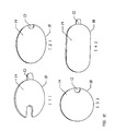
- an artificial retina device 10 is generally circular in shape with an integral grasping member (FIG. 1B) or a projecting grasping member (FIG. 1A) to grasp the device while it is being inserted.
- the device ranges from 2 mm to 20 mm in diameter and from 0.005 mm to 2 mm in thickness.
- the device 10 may be round (FIG. 1C [3]), oval (FIG. 1C [4]) elliptical (FIG. 1C [2]), or irregular (FIG. 1C [1]) in shape.
- the surface contours may be flat or curved to match the curvature of the retina.
- the edges or selected areas of the anterior 14 or posterior 16 (FIG. 2A) surfaces may be fashioned with ridges or other protrusions to improve stability within the retina and to improve biological acceptability.
- the device may also have ledges, lips or loops to aid manipulation during implantation. In addition, it may also have openings (not shown) between the two surfaces to allow passage of intraretinal nourishment and tissue ingrowth to maintain the device securely in the retina.
- the device may also be comprised of multiple smaller devices joined together by their edges.
- FIG. 1D three devices may be joined together in an articulated fashion to increase implant size and to conform to the curved retina.
- the devices are joined with an inert adhesive such as a silicon cement.
- the concavity of the articulated device is the anterior surface facing incoming light (14) and the convexity of the device is the posterior surface facing the retinal pigment epithelium (16).
- a device 10 may also have a flexible member such as a thin suture 13 attached (FIG. 1E) to facilitate removal of the implant as needed.
- Suture 13 is fashioned from an inert material such as nylon and may be left in place or removed via traction on the suture while securing the implant.
- an insertion guide 78 may be used to insert implant 10 into the eye.
- the guide portion 79 of the device is an elongated, flattened tubular structure fashioned from a curved and compressed tube of clear flexible material such as teflon or polyethylene with lips 83a and 83b at each end.
- the pusher portion 80 of the device is adapted to slide through guide portion 79, and is made from a similar material.
- Pusher 80 has multiple serrations 81 at one end to allow positive contact while pushing implant 10.
- implant 10 is placed within the guide 79 followed by pusher 80.
- the completed assembly 82 (Fig. 6) is inserted into the desired intraretinal location via a scleral incision into the intraretinal space.
- the pusher 80 is then pushed while retracting the guider 79 thus depositing the implant pass lip 83b into the intraretinal space.
- lip 83b can be used to lift and separate the desired retinal layers, and be used to deposit the implant accurately in the desired location.
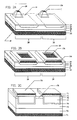
- the details of the photodiode construction of the artificial retina device of the present invention consist of multiple layers of both pure and doped silicon deposited and etched.
- An insulated or noninsulated polysilicon active electrode structure 13a projects from the surface in one embodiment (FIG. 2A), or a flat polysilicon active electrode surface 13b is constructed in another alternative embodiment (FIG. 2B) to transfer a current from the photodiode to the overlying photoreceptor, bipolar and inner retinal cell layers as explained in detail below.
- the polysilicon electrode structure 13a or 13b can be made by standard semiconductor plasma and/or wet etch techniques.
- a chromium base 72 and a gold surface 71 may be substituted for the conductive surfaces of the active electrode and common electrical ground.
- a NiP device employs a P-type substrate 75.
- a layer of chromium 72 is deposited on the posterior electrical ground surface followed by deposition of a layer of gold 71.
- a P+ layer 78 is then ion-implanted onto the anterior surface followed by ion implantation of individual N tubs 77.
- An automatic i layer forms at the junction of the N and P+ and N and P layers.
- a thin layer, transparent to light, of chromium 72 and then gold 71 is deposited over each N tub 77. This produces a NiP device.
- the N and P layers may be reversed to produce a PiN device.
- a PiN device would not require ion implantation of a P+ layer 78.
- conductive materials can be used as well for these layers: aluminum, platinum, conductive silicon or combinations of these materials.
- the artificial retina device of the present invention is, therefore, a large array of photovoltaic microphotodiodes of the PiN type.
- Each microphotodiode (Figs. 2A and 2B) consists of a shallow P-doped photoactive layer 18 overlaying an intrinsic layer 20 which in turn overlays a N-doped layer 6.
- a conductive layer 22 of polysilicon that forms the common complimentary electrode or ground.
- a common complimentary electrode is shown, but the device can be constructed with a discrete complimentary electrode for each microphotodiode.
- a layer of silicon nitrate 24 covering the entire surface except for openings (or on the unmasked areas) 26 that establish electrode contact areas for the polysilicon active electrode 13a (or 13b).
- the PiN layers may be reversed (NIP) or modified to facilitate reversal of the device polarity.
- a plurality of nodes 28 are formed from a plurality of microphotodiodes described above.
- the designed current output of each self-powered photodiode node is on the order of 50 nA when the device is exposed to average room lighting. However, the electrical current output may be designed to be greater or less than this value depending upon the stimulation requirement of the overlying cell layer.
- a supplemental bias activation current may also be provided by an insulated wire or series of insulated wires leading from the device from the eye into an external or internally implanted battery unit.
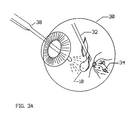
- the device 10 of this invention is inserted into the vitreous cavity of the eye 30 via a pars plana incision 32.
- a horizontal incision 34 (FIG. 3B) is then made through the retina from the vitreous side in the temporal portion of the posterior pole into the potential space between the photoreceptor layer and the retinal pigment epithelium.
- a horizontal incision 34 made at this location will avoid cutting inner retinal vasculature and will be parallel to coursing nerve fiber layers 36, therefore, also avoiding their injury.
- Illumination for the surgical procedure is provided by a optical fiber light pipe 38.
- the potential space is then be opened by canula irrigation of a balanced salt solution into the intraretinal space.
- the device is then placed into the intraretinal cavity (FIG. 3C) at the posterior pole under the macula area. Specifically, the device is placed between the retinal pigment epithelium 58 ( Figure 4) and photoreceptor layer 54, or if photoreceptor layer 54 is atrophied or lost then between the retinal pigment epithelium 58 and the bipolar and horizontal cell layer 52. The device is positioned such that the electrical ground 22 (or 74) is overlaying the retinal pigment epithelium 58 and the active electrode 13a (or 13b or 73) faces the incident light.
- endolaserphtocoagulation or endocautery burns 39 are made around the periphery of the device to secure the device.
- the scar tissue so formed around the periphery of the device will prevent the device from moving out of position.
- Endolaserphotocoagulation or endocautery 39 may also be used to seal the retinal incision.
- Air or other approved gaseous compounds may also be injected into the vitreous cavity to tamponade the retinal opening during healing. The pars plana incision will be closed in the usual surgical manner.
- An alternate method for implantation would involve making an incision through the sclera just posterior to the ora serata. Dissection would proceed through the choroid, choriocapillaris, Bruch's membrane and retinal pigment epithelium under stereo operating microscope control into the potential space between the inner and outer retinal layers. The artificial retinal implant would then be inserted into this space and directed posteriorly towards the macula by a pushing action imparted by a formed curved iris spatula or by use of the insertion guide 78. The device will rest in the macula area of posterior pole of the eye between the inner and outer retinal layers.
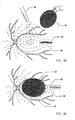
- the layers of the eye at the posterior pole from inside to outside are shown in FIG. 4: internal limiting membrane 40, nerve fiber layer 42, ganglion and amacrine cell layer 44, inner plexiform 46, inner nuclear layer 48, outer plexiform 50, outer nuclear and bipolar cell layer 52, and photoreceptor layer 54, all of which constitute the inner retinal layer 56.
- the retinal pigment epithelium 58, and Bruch's membrane 60 constitute the outer retinal layer 62.
- the choriocapillaris 64, and choroid 66 comprise the choroidal vasculature 68.
- the outer coat of the eye is the sclera 70.
- an amplitude-modulated current varying with illumination, produced by each photodiode of the device 10 will stimulate the overlying inner retinal layer consisting of photoreceptors (if present) and their cell bodies 54, 52, bipolar cells 48 and horizontal cells 52.
- cells 48-52 normally both receive and produce analog amplitude-modulated currents, the analog amplitude-modulated output of the device is well suited for stimulation of these cells.
- the amplitude-modulated signals of the bipolar cells 48 are then modified and converted by the amacrine and ganglion cells 44 to a frequency-modulated signal as is the normal biological event in the innermost area of the inner retinal layer for distant transmission through the optic nerve to the lateral geniculate area of the brain.
- each photodiode will be automatically amplitude modulated corresponding to the intensity of the incident light
- the resulting stimulation and signal current production of the overlying photoreceptor or bipolar cell layer will also be amplitude modulated thereby duplicating the normal amplitude-modulated character of these cells.
- Stimulating inner retina 56 at the above indicated location will also allow the normal function of the horizontal cell on-off receptor fields thereby allowing contrast appreciation.
Abstract
Description
- The present invention is directed to a medical product and operation procedure which can be used to correct vision loss or even complete blindness caused by certain retinal diseases. A variety of retinal diseases, for example, cause vision loss or blindness by destruction of the choroid, choriocapillaris, and the outer retinal layers. The outer layers include Bruch's membrane and retinal pigment epithelium, the loss of which results in degeneration of the inner retinal photoreceptor layer. These diseases, however, often spare much of the remaining inner retinal layers of the outer nuclear, outer plexiform, inner nuclear, inner plexiform, ganglion cell and nerve fiber layers.
- The current invention involves the use of an electronic device, a photosensitive array, that is capable of mimicking the signals that would otherwise be produced by the damaged inner retinal photoreceptor layer. When the device is implanted between the inner and outer retinal layers, it will stimulate the inner layer to provide significantly useful formed vision to a patient in a manner never before available.
- Prior attempts have been made to produce vision by stimulating various portions of the retina. One such attempt involved an externally powered but internally located photosensitive array device with its photoactive surface and electrode surface on opposite sides. The device was to stimulate the nerve fiber layer via direct placement on this layer from the vitreous body side. The success of this device is unlikely due to it having to duplicate the complex frequency modulate neural signals of the nerve fiber layer. Furthermore, the nerve fiber layer runs in a general radial course with many layers of overlapping fibers from different portions of the retina making selection of the appropriate nerve fiber to stimulate extremely difficult if not impossible. The production of useful formed visual imagery is therefore highly unlikely. No device of this type has been known to have been constructed that produced any type of formed image.
- Another prior device involved a unit consisting of a supporting base onto which a photosensitive material such as selenium is coated. This device was to have been inserted through an external scleral incision made at the posterior pole resting between the sclera and choroid or between the choroid and retina. Light stimulation would then cause a potential to develop on the photosensitive surface causing ions to be produced which would then theoretically migrate into the retina causing stimulation. However, having no discrete surface structure to restrict the directional flow of charges, lateral migration and diffusion of charges would be allowed thereby preventing any resolution capability. Placement of this device between the sclera and choroid would also virtually block the discrete migration of ions to the photoreceptor and inner retinal layers due to the presence of the choroid, choriocapillaris, Bruch's membrane and the retinal pigment epithelial layer. Placement of the device between the choroid and the retina would still interpose Bruch's membrane and the retinal pigment epithelial layer in the pathway of discrete ion migration. Also, as this device would have had to be inserted into or through the highly vascular choroid of the posterior pole, severe subchoroidal, intraretinal and or intraorbital hemorrhage would likely have resulted along with disruption of blood flow to the posterior pole. One such device was apparently constructed and implanted into a patient's eye resulting in reported light perception but no formed imagery.
- The artificial retina device of this invention circumvents the limitations of previous devices. It is composed of a plurality of discrete photodiodes with their individual electrodes disposed on one surface of a substrate, the photodiodes each being connected to a common electrical ground on the other side of the substrate. Each photodiode includes an active electrode layer overlaying a photosensitive layer, and each is connected to an electrical ground. The photodiodes have electrical outputs that correspond to the amplitude of the light incident on said device, whereby said device can be implanted in the eye intermediate the inner retinal layer and the retinal pigment epithelium of outer layer of the retina, so that each of said photodiodes will stimulate directly individual or small groups of cells in the inner retinal layer corresponding to the light incident on said device.
- When inserted within the retina between the inner and outer retinal layers, in the potential space zone, an amplitude-modulated electric potential, varying with illumination, produced by each photodiode will stimulate the overlying inner retinal layer consisting of photoreceptors, bipolar cells and horizontal cells. As these cells normally both receive and produce analog amplitude-modulated currents, the analog amplitude-modulated output of the device is well suited for stimulation of these cells. The amplitude-modulated signals of the bipolar cells are then modified and converted by the amacrine and ganglion cells to a frequency-modulated signal as is the normal biological event in the innermost area of the inner retinal layer for distant transmission through the optic nerve to the lateral geniculate area of the brain. Because the complex conversion of the amplitude-modulated signal to the frequency-modulated signal is left to intrinsic retinal mechanisms, the formed vision produced is much enhanced compared to devices that attempt to stimulate the nerve fiber layer directly with electronic and amplifier reconstructed frequency-modulated signals.
- Such a device has been fabricated and successfully implanted in the intraretinal space of several rabbit eyes. Electrical responses produced by the overlying retina following stimulation of the implant, compatible with visual function, has also been recorded.
-
- FIG. 1A is a perspective view of an artificial retina device of the present invention;
- FIG. 1B is a perspective view of an alternative form of an artificial retina device of the present invention;
- FIG. 1C [1]-[4] are perspective views of four alternative embodiments of the present invention;
- FIG. 1D is a perspective view of an artificial retinal device comprised of several smaller devices secured together in a linear and articulated fashion;
- FIG. 1E is a perspective view of an artificial retinal device with a thin suture attached for retrieval purposes;
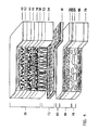
- FIG. 2A is a perspective, cross-sectional view of a first photodiode array for use in an artificial retina device of the present invention;
- FIG. 2B is a perspective, cross-sectional view of a second photodiode array for use in an artificial retina device of the present invention;
- FIG. 2C is a perspective, cross sectional view of a third type of photodiode array arrangement used in the artificial retina device of the present invention;
- FIG. 3A-3C illustrate steps in a surgical procedure for implanting an artificial retina device of the present invention; and
- FIG. 4 is an exploded, cross-sectional view of an artificial retinal device of the present invention as implanted in the eye;
- FIG. 5 is a perspective view of the separate components of an insertion guide that may be used to insert the implant into the eye;
- FIG. 6 is a perspective view of the assembled components of the insertion guide of FIG. 5.
- In one embodiment of this invention, an
artificial retina device 10 is generally circular in shape with an integral grasping member (FIG. 1B) or a projecting grasping member (FIG. 1A) to grasp the device while it is being inserted. The device ranges from 2 mm to 20 mm in diameter and from 0.005 mm to 2 mm in thickness. - As shown in FIG. 1C, the
device 10 may be round (FIG. 1C [3]), oval (FIG. 1C [4]) elliptical (FIG. 1C [2]), or irregular (FIG. 1C [1]) in shape. The surface contours may be flat or curved to match the curvature of the retina. The edges or selected areas of the anterior 14 or posterior 16 (FIG. 2A) surfaces may be fashioned with ridges or other protrusions to improve stability within the retina and to improve biological acceptability. The device may also have ledges, lips or loops to aid manipulation during implantation. In addition, it may also have openings (not shown) between the two surfaces to allow passage of intraretinal nourishment and tissue ingrowth to maintain the device securely in the retina. - The device may also be comprised of multiple smaller devices joined together by their edges. In one embodiment (FIG. 1D) three devices may be joined together in an articulated fashion to increase implant size and to conform to the curved retina. The devices are joined with an inert adhesive such as a silicon cement. The concavity of the articulated device is the anterior surface facing incoming light (14) and the convexity of the device is the posterior surface facing the retinal pigment epithelium (16).
- A
device 10 may also have a flexible member such as athin suture 13 attached (FIG. 1E) to facilitate removal of the implant as needed.Suture 13 is fashioned from an inert material such as nylon and may be left in place or removed via traction on the suture while securing the implant. - As shown in FIG. 5, an
insertion guide 78 may be used to insertimplant 10 into the eye. Theguide portion 79 of the device is an elongated, flattened tubular structure fashioned from a curved and compressed tube of clear flexible material such as teflon or polyethylene withlips pusher portion 80 of the device is adapted to slide throughguide portion 79, and is made from a similar material.Pusher 80 hasmultiple serrations 81 at one end to allow positive contact while pushingimplant 10. In operation,implant 10 is placed within theguide 79 followed bypusher 80. The completed assembly 82 (Fig. 6) is inserted into the desired intraretinal location via a scleral incision into the intraretinal space. Thepusher 80 is then pushed while retracting theguider 79 thus depositing theimplant pass lip 83b into the intraretinal space. Withdevice 78,lip 83b can be used to lift and separate the desired retinal layers, and be used to deposit the implant accurately in the desired location. - As shown in FIGS. 2A and 2B, the details of the photodiode construction of the artificial retina device of the present invention consist of multiple layers of both pure and doped silicon deposited and etched. An insulated or noninsulated polysilicon active electrode structure 13a projects from the surface in one embodiment (FIG. 2A), or a flat polysilicon
active electrode surface 13b is constructed in another alternative embodiment (FIG. 2B) to transfer a current from the photodiode to the overlying photoreceptor, bipolar and inner retinal cell layers as explained in detail below. In particular, thepolysilicon electrode structure 13a or 13b can be made by standard semiconductor plasma and/or wet etch techniques. - In another embodiment of the invention (Fig. 2C), a
chromium base 72 and agold surface 71 may be substituted for the conductive surfaces of the active electrode and common electrical ground. This embodiment, a NiP device, employs a P-type substrate 75. A layer ofchromium 72 is deposited on the posterior electrical ground surface followed by deposition of a layer ofgold 71. AP+ layer 78 is then ion-implanted onto the anterior surface followed by ion implantation ofindividual N tubs 77. An automatic i layer forms at the junction of the N and P+ and N and P layers. A thin layer, transparent to light, ofchromium 72 and thengold 71 is deposited over eachN tub 77. This produces a NiP device. The N and P layers may be reversed to produce a PiN device. A PiN device would not require ion implantation of aP+ layer 78. - Other conductive materials can be used as well for these layers: aluminum, platinum, conductive silicon or combinations of these materials.
- The artificial retina device of the present invention is, therefore, a large array of photovoltaic microphotodiodes of the PiN type. Each microphotodiode (Figs. 2A and 2B) consists of a shallow P-doped
photoactive layer 18 overlaying an intrinsic layer 20 which in turn overlays a N-dopedlayer 6. On the posterior surface oflayer 6 is deposited aconductive layer 22 of polysilicon that forms the common complimentary electrode or ground. A common complimentary electrode is shown, but the device can be constructed with a discrete complimentary electrode for each microphotodiode. - On the anterior surface is deposited a layer of
silicon nitrate 24 covering the entire surface except for openings (or on the unmasked areas) 26 that establish electrode contact areas for the polysilicon active electrode 13a (or 13b). The PiN layers may be reversed (NIP) or modified to facilitate reversal of the device polarity. As can be seen in FIGS. 2A and 2B, a plurality ofnodes 28 are formed from a plurality of microphotodiodes described above. The designed current output of each self-powered photodiode node is on the order of 50 nA when the device is exposed to average room lighting. However, the electrical current output may be designed to be greater or less than this value depending upon the stimulation requirement of the overlying cell layer. A supplemental bias activation current may also be provided by an insulated wire or series of insulated wires leading from the device from the eye into an external or internally implanted battery unit. - As shown in FIG. 3A, the
device 10 of this invention is inserted into the vitreous cavity of the eye 30 via apars plana incision 32. A horizontal incision 34 (FIG. 3B) is then made through the retina from the vitreous side in the temporal portion of the posterior pole into the potential space between the photoreceptor layer and the retinal pigment epithelium. Ahorizontal incision 34 made at this location will avoid cutting inner retinal vasculature and will be parallel to coursing nerve fiber layers 36, therefore, also avoiding their injury. Illumination for the surgical procedure is provided by a opticalfiber light pipe 38. The potential space is then be opened by canula irrigation of a balanced salt solution into the intraretinal space. - The device is then placed into the intraretinal cavity (FIG. 3C) at the posterior pole under the macula area. Specifically, the device is placed between the retinal pigment epithelium 58 (Figure 4) and
photoreceptor layer 54, or ifphotoreceptor layer 54 is atrophied or lost then between the retinal pigment epithelium 58 and the bipolar andhorizontal cell layer 52. The device is positioned such that the electrical ground 22 (or 74) is overlaying the retinal pigment epithelium 58 and the active electrode 13a (or 13b or 73) faces the incident light. - After insertion, a series of endolaserphtocoagulation or endocautery burns 39 are made around the periphery of the device to secure the device. The scar tissue so formed around the periphery of the device will prevent the device from moving out of position. Endolaserphotocoagulation or
endocautery 39 may also be used to seal the retinal incision. Air or other approved gaseous compounds may also be injected into the vitreous cavity to tamponade the retinal opening during healing. The pars plana incision will be closed in the usual surgical manner. - An alternate method for implantation would involve making an incision through the sclera just posterior to the ora serata. Dissection would proceed through the choroid, choriocapillaris, Bruch's membrane and retinal pigment epithelium under stereo operating microscope control into the potential space between the inner and outer retinal layers. The artificial retinal implant would then be inserted into this space and directed posteriorly towards the macula by a pushing action imparted by a formed curved iris spatula or by use of the
insertion guide 78. The device will rest in the macula area of posterior pole of the eye between the inner and outer retinal layers. - The layers of the eye at the posterior pole from inside to outside are shown in FIG. 4: internal limiting
membrane 40,nerve fiber layer 42, ganglion andamacrine cell layer 44,inner plexiform 46, innernuclear layer 48,outer plexiform 50, outer nuclear andbipolar cell layer 52, andphotoreceptor layer 54, all of which constitute the innerretinal layer 56. The retinal pigment epithelium 58, and Bruch's membrane 60 constitute the outerretinal layer 62. The choriocapillaris 64, and choroid 66 comprise thechoroidal vasculature 68. The outer coat of the eye is thesclera 70. - With regard to FIG. 4, when the
device 10 is inserted within the retina between the inner retinal layer 56 (that may or may not contain a functional photoreceptor layer 54) and the outerretinal layer 62, in thepotential space zone 72, an amplitude-modulated current varying with illumination, produced by each photodiode of thedevice 10 will stimulate the overlying inner retinal layer consisting of photoreceptors (if present) and theircell bodies bipolar cells 48 andhorizontal cells 52. As cells 48-52 normally both receive and produce analog amplitude-modulated currents, the analog amplitude-modulated output of the device is well suited for stimulation of these cells. The amplitude-modulated signals of thebipolar cells 48 are then modified and converted by the amacrine andganglion cells 44 to a frequency-modulated signal as is the normal biological event in the innermost area of the inner retinal layer for distant transmission through the optic nerve to the lateral geniculate area of the brain. - As the output of each photodiode will be automatically amplitude modulated corresponding to the intensity of the incident light, the resulting stimulation and signal current production of the overlying photoreceptor or bipolar cell layer will also be amplitude modulated thereby duplicating the normal amplitude-modulated character of these cells. Stimulating
inner retina 56 at the above indicated location will also allow the normal function of the horizontal cell on-off receptor fields thereby allowing contrast appreciation. - Although recognizable color information output may not occur from the stimulated cells, significant formed vision output should develop serving as input for the amacrine and ganglion cell layers which will modify the signal into a frequency modulated signal for transmission to the lateral geniculate area of the brain.
- While several embodiments of this invention are described, others will be apparent to those of ordinary skill in the art. Such other embodiments are to be included within the scope of the present invention, unless the claims that follow expressly state otherwise.
Claims (30)
- An artificial retina device comprising:
a plurality of discrete photodiodes, disposed on one surface of a substrate said photodiodes each including an active electrode layer overlaying a photosensitive layer, each photodiode being connected to an electrical ground, wherein said active electrode layer and ground are made from materials selected from aluminum, platinum, chromium, gold, conductive silicon, or combinations thereof, said photodiodes having electrical outputs that correspond to the amplitude of light incident on said device, whereby said device can stimulate individual or small groups of cells in the inner retinal layer of the eye, corresponding to the light incident on said device. - The artificial retina device of Claim 1, wherein said device is from 2 mm to 20 mm in its maximum width, and from 0.005 mm to 2 mm between said two surfaces.
- An artificial retina device, comprising:
a plurality of discrete photodiodes disposed on one surface of a substrate, said photodiodes each including an active electrode layer overlaying a photosensitive layer, each photodiode being connected to an electrical ground, said photodiodes having electrical outputs that correspond to the amplitude of the light incident on said device, whereby said device can be implanted in the eye intermediate the inner retinal layer and the retinal pigment epithelium of outer layer of the retina, so that each of said photodiodes will stimulate directly individual or small groups of cells in the inner retinal layer corresponding to the light incident on said device. - The artificial retina device of Claim 3 wherein said device is from 3 mm to 20 mm in its maximum width and from 0.005 mm to 2 mm between said two surfaces.
- An artificial retina device according to Claims 3 or 4, wherein the edges of said implant are rounded to facilitate insertion into the intraretinal space without tearing the retina.
- An artificial retina device according to any one of Claims 3 to 5, wherein said device includes a flexible member extending therefrom.
- The retinal implant device of Claim 6 wherein said flexible member comprises a suture.
- An artificial retina device according to any one of Claims 3 to 7 including plural articulated portions so as to conform to a curved retinal layer.
- The retinal implant device of Claim 8 wherein said articulated portions include at least one flexible joint.
- An artificial retina device, according to any one of Claims 3 to 9 wherein said plurality of discrete photodiodes comprises:
a plurality of discrete PiN or NiP photodiodes the resistances of said photodiodes ranging from 1 ohm-cm to 50,000 ohm-cm. - The retinal implant device of any one of Claims 3 to 9 wherein said photosensitive layer comprises a P-doped layer, and said device further includes an intrinsic layer and a N-doped layer, said intrinsic layer being disposed between said P-doped layer and said N-doped layer.
- The retinal implant device of any one of Claims 3 to 9 wherein said photosensitive layer comprises a N-doped layer and said device further includes an intrinsic layer and a P-doped layer, said intrinsic layer being disposed between said N-doped layer and said P-doped layer.
- The retinal implant device of Claims 11 or 12 wherein said active electrode is formed from polysilicon.
- The artificial retina device of any one of the preceding Claims that further includes a grasping member.
- The artificial retina device of any one of the preceding Claims further including a plurality of openings between said two surfaces.
- The artificial retina device of any one of the preceding Claims wherein one or both surfaces are curved.
- The retinal implant device of any one of the preceding Claims, wherein said first surface includes a plurality of protuberances that extend therefrom.
- The retinal implant device of any one of the preceding Claims wherein said first surface is flat.
- A device for implanting an artificial retina device into the eye, comprising:
an elongated flattened tubular member curved along its length with a lip on one end;
a pusher member adapted to slide within said elongated tubular member whereby an artificial retina device can be implanted into the eye through an incision by introducing said tubular member through said incision, and pushing the retina device through said tubular member with said pusher member until said retina device is adjacent said lip. - The device of Claim 19 wherein said pusher member has serrations at one end.
- A surgical procedure for implanting into the eye an artificial retina device including a plurality of discrete photodiodes, said procedure comprising:
making a horizontal incision temporal to the macula, parallel to and through the nerve fiber layer;
opening the potential space within the retina;
inserting said device into said space intermediate the inner retinal layer and the retinal pigment epithelium of the outer layer of the retina with said photodiodes facing light incident into the eye; and
closing said incision and space. - The surgical procedure of Claim 21 wherein said device is inserted into said space by inserting a tubular insertion guide through said incision and into said space, and passing said device through said insertion guide into said space.
- The surgical procedure of Claim 22 wherein said tubular insertion guide is a flattened tube, and said device is passed through said tube by pushing it with a pusher member.
- The surgical procedure of Claim 22 wherein said guide includes a lip on one end that is introduced into said space before said device is passed through it, said lip adapted to deposit said device in the desired location.
- The surgical procedure of Claim 23 wherein said guide and pusher member are curved.
- The surgical procedure of Claim 21 wherein said device is positioned on the macula area of the posterior pole of the eye.
- A surgical procedure for implanting a device of any one of Claims 1 to 18 comprising:
making a horizontal incision temporal to the macula, parallel to and through the nerve fiber layer;
opening the potential space within the retina by irrigating with balanced salt solution;
inserting said device into said space intermediate the inner retinal layer and the retinal pigment epithelium of outer layer of the retina with said photodiodes facing light incident into said eye;
and closing said incision and space. - The surgical procedure of Claim 27 wherein a plurality of burns are made around the periphery of said device to secure the device in position.
- A method for producing artificial vision, comprising:
making an incision through the sclera posterior to the ora serata, through the choroidal vasculature, the outer retinal layer and into the potential space between the inner and outer retinal layer; and
inserting a device of any one of Claims 1 to 18 into said space whereby it is positioned in the macula area of the posterior pole of the eye. - A method for producing artificial vision, comprising:
implanting a device of any one of Claims 1 to 18 into the potential space of the retina between the retinal pigment epithelium and the inner retinal layer with the active electrode facing light incident the eye, whereby said device intercepts light after its passage through the nerve fiber layer and inner retinal layers of the eye, and produces discrete stimulation from inside the retina of bipolar cells, horizontal cells, amacrine cells and ganglion cells.
Applications Claiming Priority (4)
| Application Number | Priority Date | Filing Date | Title |
|---|---|---|---|
| US390562 | 1982-06-21 | ||
| US07/390,562 US5016633A (en) | 1989-08-08 | 1989-08-08 | Artificial retina device |
| US07/549,094 US5024223A (en) | 1989-08-08 | 1990-07-06 | Artificial retina device |
| US549094 | 1990-07-06 |
Publications (3)
| Publication Number | Publication Date |
|---|---|
| EP0460320A2 true EP0460320A2 (en) | 1991-12-11 |
| EP0460320A3 EP0460320A3 (en) | 1993-02-24 |
| EP0460320B1 EP0460320B1 (en) | 1998-01-07 |
Family
ID=27013194
Family Applications (1)
| Application Number | Title | Priority Date | Filing Date |
|---|---|---|---|
| EP90308575A Expired - Lifetime EP0460320B1 (en) | 1989-08-08 | 1990-08-03 | Artificial retina device |
Country Status (5)
| Country | Link |
|---|---|
| US (1) | US5024223A (en) |
| EP (1) | EP0460320B1 (en) |
| CA (1) | CA2022544C (en) |
| DE (1) | DE69031908T2 (en) |
| ES (1) | ES2110410T3 (en) |
Cited By (28)
| Publication number | Priority date | Publication date | Assignee | Title |
|---|---|---|---|---|
| WO1997013551A1 (en) * | 1995-10-11 | 1997-04-17 | Trustees Of Boston University | Method and apparatus for improving the function of sensory cells |
| WO1998017343A1 (en) | 1996-10-23 | 1998-04-30 | Eberhard-Karls-Universität Tübingen Universitätsklinikum | Retina implant |
| WO1998017344A1 (en) | 1996-10-23 | 1998-04-30 | Eberhard-Karls-Universität Tübingen Universitätsklinikum | Optically controllable microelectrode arrangement for stimulating cells, in particular a retina implant |
| WO1999015119A1 (en) * | 1997-09-19 | 1999-04-01 | Eberhard-Karls-Universität Tübingen | Device for accessing the sub-retinal space of an eye |
| DE19705987C2 (en) * | 1996-10-23 | 1999-09-09 | Univ Eberhard Karls | Optically controllable microelectrode arrangement for stimulating cells, in particular a retina implant |
| EP0957975A1 (en) * | 1995-06-06 | 1999-11-24 | CHOW, Vincent | Multi-phasic microphotodiode retinal implant and adaptive imaging retinal stimulation system |
| WO2000067838A1 (en) * | 1999-05-07 | 2000-11-16 | Eberhard-Karls-Universität Tübingen Universitätsklinikum | Retina implant |
| WO2002041814A2 (en) * | 2000-11-21 | 2002-05-30 | Massachusetts Institute Of Technology | Inflatable neural prosthesis |
| WO2002087687A1 (en) | 2001-04-28 | 2002-11-07 | Td Verwaltungs Gmbh | Microcontact structure for implantation in a mammal, especially a human being |
| GB2379784A (en) * | 2001-07-30 | 2003-03-19 | Hewlett Packard Co | Providing power and control to electrical devices |
| WO2003061537A1 (en) * | 2002-01-17 | 2003-07-31 | Masachusetts Eye And Ear Infirmary | Minimally invasive retinal prosthesis |
| WO2004067088A1 (en) | 2003-01-31 | 2004-08-12 | Eberhard-Karls-Univer Sität Tübingen | Retina implant for stimulating a retina according to incident light |
| WO2005000395A1 (en) | 2003-06-23 | 2005-01-06 | Eberhard-Karls-Universität Tübingen Universitätsklinikum | Active retina implant comprising a plurality of picture elements |
| DE102004002379A1 (en) * | 2004-01-15 | 2005-08-18 | Iip-Technologies Gmbh | Neurological tool |
| WO2005087309A1 (en) | 2004-03-12 | 2005-09-22 | Imi Intelligent Medical Implants Ag | Stimulation electrode |
| US7158836B2 (en) | 2001-03-30 | 2007-01-02 | Satoshi Suzuki | Electrode member for retinal stimulation, and artificial retinal device using the electrode member |
| WO2008020849A1 (en) * | 2006-08-16 | 2008-02-21 | Second Sight Medical Products, Inc. | Surgical tool for electrode implantation |
| EP1958577A3 (en) * | 1999-01-05 | 2008-10-01 | Second Sight Medical Products, Inc. | Apparatus for intraocular retinal implant insertion |
| WO2010105728A2 (en) | 2009-03-20 | 2010-09-23 | Retina Implant Ag | Active retinal implant |
| DE102009015389A1 (en) | 2009-03-20 | 2010-09-30 | Retina Implant Ag | Active retinal implant for eye for serving to counteract loss of vision due to degenerations of retina, has array of stimulation elements that are designed as radiation-emitting elements |
| US8231637B2 (en) | 2002-07-26 | 2012-07-31 | Second Sight Medical Products, Inc. | Surgical tool for electrode implantation |
| US8612017B2 (en) | 2006-09-26 | 2013-12-17 | Retina Implant Ag | Implantable device |
| US8849401B2 (en) | 2006-09-26 | 2014-09-30 | Retina Implant Ag | Implantable device |
| US9199080B2 (en) | 2011-09-12 | 2015-12-01 | Okuvision Gmbh | Method for treating an eye |
| EP1874397B1 (en) | 2005-04-28 | 2016-06-01 | Second Sight Medical Products, Inc. | Flexible circuit electrode array |
| DE102016105174A1 (en) | 2016-03-21 | 2017-09-21 | NMI Naturwissenschaftliches und Medizinisches Institut an der Universität Tübingen | Active retina implant |
| WO2018146032A1 (en) | 2017-02-10 | 2018-08-16 | Retina Implant Ag | Implant device having an optical interface |
| CN110628623A (en) * | 2019-09-10 | 2019-12-31 | 大连理工大学 | Visual cognition chip |
Families Citing this family (75)
| Publication number | Priority date | Publication date | Assignee | Title |
|---|---|---|---|---|
| US5476494A (en) * | 1992-09-11 | 1995-12-19 | Massachusetts Institute Of Technology | Low pressure neural contact structure |
| US5556423A (en) * | 1993-05-03 | 1996-09-17 | Alan Y. Chow | Independent photoelectric artificial retina device and method of using same |
| US5397350A (en) * | 1993-05-03 | 1995-03-14 | Chow; Alan Y. | Independent photoelectric artificial retina device and method of using same |
| US5597381A (en) * | 1993-06-03 | 1997-01-28 | Massachusetts Eye And Ear Infirmary | Methods for epi-retinal implantation |
| US5895415A (en) * | 1995-06-06 | 1999-04-20 | Optobionics Corporation | Multi-phasic microphotodiode retinal implant and adaptive imaging retinal stimulation system |
| US5873901A (en) * | 1995-06-30 | 1999-02-23 | Space Vacuum Epitaxy Center University Of Houston | Treating retinal damage by implanting thin film optical detectors |
| DE19529371C3 (en) * | 1995-08-10 | 2003-05-28 | Nmi Univ Tuebingen | Microelectrode array |
| US5837995A (en) * | 1996-11-25 | 1998-11-17 | Alan Y. Chow | Wavelength-controllable voltage-phase photodiode optoelectronic switch ("opsistor") |
| US5836996A (en) * | 1996-12-30 | 1998-11-17 | Doorish; John F. | Artificial retina |
| US5865839A (en) * | 1996-12-30 | 1999-02-02 | Doorish; John F. | Artificial retina |
| US5935155A (en) * | 1998-03-13 | 1999-08-10 | John Hopkins University, School Of Medicine | Visual prosthesis and method of using same |
| US5944747A (en) * | 1998-03-13 | 1999-08-31 | Johns Hopkins University | Method for preferential outer retinal stimulation |
| US6324429B1 (en) * | 1998-05-08 | 2001-11-27 | Massachusetts Eye And Ear Infirmary | Chronically implantable retinal prosthesis |
| US6448089B1 (en) | 1999-10-12 | 2002-09-10 | Aurora Biosciences Corporation | Multiwell scanner and scanning method |
| US6586257B1 (en) | 1999-10-12 | 2003-07-01 | Vertex Pharmaceuticals Incorporated | Multiwell scanner and scanning method |
| US6814933B2 (en) * | 2000-09-19 | 2004-11-09 | Aurora Biosciences Corporation | Multiwell scanner and scanning method |
| US6389317B1 (en) | 2000-03-31 | 2002-05-14 | Optobionics Corporation | Multi-phasic microphotodetector retinal implant with variable voltage and current capability |
| US20040039401A1 (en) * | 2000-03-31 | 2004-02-26 | Chow Alan Y. | Implant instrument |
| DE10020846A1 (en) * | 2000-04-28 | 2001-12-06 | Intelligent Implants Gmbh | Micro-contact structure for neuroprostheses for implantation on nerve tissue and method therefor |
| US6427087B1 (en) * | 2000-05-04 | 2002-07-30 | Optobionics Corporation | Artificial retina device with stimulating and ground return electrodes disposed on opposite sides of the neuroretina and method of attachment |
| US7615356B2 (en) | 2000-07-10 | 2009-11-10 | Vertex Pharmaceuticals (San Diego) Llc | Ion channel assay methods |
| US7399599B2 (en) | 2000-07-10 | 2008-07-15 | Vertex Pharmaceuticals (San Diego) Llc | Ion channel assay methods |
| DE10052670A1 (en) * | 2000-10-24 | 2002-05-08 | Forschungszentrum Juelich Gmbh | Measuring arrangement for the detection of a one- or multi-dimensional distribution of a chemical or biochemical component |
| US7149586B2 (en) * | 2002-03-28 | 2006-12-12 | Second Sight Medical Products, Inc. | Variable pitch electrode array |
| US8060211B2 (en) | 2001-02-13 | 2011-11-15 | Second Sight Medical Products, Inc. | Method of reducing retinal stress caused by an implantable retinal electrode array |
| US7338522B2 (en) * | 2001-02-13 | 2008-03-04 | Second Sight Medical Products, Inc. | Implantable retinal electrode array configuration for minimal retinal damage and method of reducing retinal stress |
| US7037943B2 (en) | 2001-04-10 | 2006-05-02 | Optobionics Corporation | Retinal treatment method |
| US20050033202A1 (en) * | 2001-06-29 | 2005-02-10 | Chow Alan Y. | Mechanically activated objects for treatment of degenerative retinal disease |
| US7031776B2 (en) * | 2001-06-29 | 2006-04-18 | Optobionics | Methods for improving damaged retinal cell function |
| US20050004625A1 (en) * | 2001-06-29 | 2005-01-06 | Chow Alan Y. | Treatment of degenerative retinal disease via electrical stimulation of surface structures |
| US7146221B2 (en) * | 2001-11-16 | 2006-12-05 | The Regents Of The University Of California | Flexible electrode array for artifical vision |
| US20070265582A1 (en) * | 2002-06-12 | 2007-11-15 | University Of Southern California | Injection Devices for Unimpeded Target Location Testing |
| US20030233126A1 (en) * | 2002-06-12 | 2003-12-18 | Alfred E. Mann Institute For Biomedical Engineering | Injection devices and methods for testing implants |
| US6755530B1 (en) * | 2002-07-16 | 2004-06-29 | The United States Of America As Represented By The Administrator Of The National Aeronautics And Space Administration | Retinal light processing using carbon nanotubes |
| US8185209B2 (en) * | 2003-01-03 | 2012-05-22 | Board Of Trustees Operating Michigan State University | Methods to extend vision to infrared wavelengths |
| US7047080B2 (en) * | 2003-02-14 | 2006-05-16 | The Board Of Trustees Of The Leland Stanford Junior University | Self-sufficient retinal prosthesis powered by intraocular photovoltaic cells |
| US7483750B2 (en) * | 2003-03-21 | 2009-01-27 | Second Sight Medical Products, Inc. | Transretinal implant and method of implantation |
| US7321795B2 (en) * | 2003-03-24 | 2008-01-22 | Les Bogdanowicz | Compositions for electric stimulation of the eye |
| US7127301B1 (en) | 2003-04-28 | 2006-10-24 | Sandia Corporation | Flexible retinal electrode array |
| US8260428B2 (en) * | 2003-05-01 | 2012-09-04 | California Institute Of Technology | Method and system for training a visual prosthesis |
| US7321796B2 (en) * | 2003-05-01 | 2008-01-22 | California Institute Of Technology | Method and system for training a visual prosthesis |
| JP4412924B2 (en) * | 2003-07-01 | 2010-02-10 | 株式会社ニデック | Visual reproduction assist device |
| WO2006073421A2 (en) * | 2004-04-09 | 2006-07-13 | Solaris Nanosciences, Inc. | Method for enhancing biological photon receptors using plasmon resonance |
| ATE408432T1 (en) * | 2004-11-02 | 2008-10-15 | Sydney Biotech Pty Ltd | EXTRAOCULAR DEVICE |
| US20060148254A1 (en) * | 2005-01-05 | 2006-07-06 | Mclean George Y | Activated iridium oxide electrodes and methods for their fabrication |
| US8224454B2 (en) * | 2005-09-16 | 2012-07-17 | Second Sight Medical Products, Inc. | Downloadable filters for a visual prosthesis |
| EP2380625A1 (en) * | 2005-09-19 | 2011-10-26 | Second Sight Medical Products, Inc. | Trans-retinal flexible circuit electrode array |
| US20070250135A1 (en) * | 2006-04-21 | 2007-10-25 | Bartz-Schmidt Karl U | Compound subretinal prostheses with extra-ocular parts and surgical technique therefore |
| JP5122244B2 (en) * | 2007-11-01 | 2013-01-16 | 株式会社ニデック | Visual reproduction assist device |
| US8588920B2 (en) * | 2007-11-21 | 2013-11-19 | The Trustees Of Boston College | Apparatus and methods for visual perception using an array of nanoscale waveguides |
| TWI356691B (en) * | 2008-02-19 | 2012-01-21 | Ind Tech Res Inst | Artificial optic nerve, artificial retina chip mod |
| US8428740B2 (en) | 2010-08-06 | 2013-04-23 | Nano-Retina, Inc. | Retinal prosthesis techniques |
| US8718784B2 (en) * | 2010-01-14 | 2014-05-06 | Nano-Retina, Inc. | Penetrating electrodes for retinal stimulation |
| US8442641B2 (en) | 2010-08-06 | 2013-05-14 | Nano-Retina, Inc. | Retinal prosthesis techniques |
| US8150526B2 (en) * | 2009-02-09 | 2012-04-03 | Nano-Retina, Inc. | Retinal prosthesis |
| US8706243B2 (en) | 2009-02-09 | 2014-04-22 | Rainbow Medical Ltd. | Retinal prosthesis techniques |
| US20100241060A1 (en) * | 2009-03-18 | 2010-09-23 | Roizman Keith | Surgical devices and methods |
| ES2963295T3 (en) | 2010-07-12 | 2024-03-26 | Univ Southern California | Biocompatible substrate to facilitate interconnections between stem cells and target tissues and methods to implant it |
| US8571669B2 (en) | 2011-02-24 | 2013-10-29 | Nano-Retina, Inc. | Retinal prosthesis with efficient processing circuits |
| WO2012149468A2 (en) | 2011-04-29 | 2012-11-01 | University Of Southern California | Instruments and methods for the implantation of cell-seeded substrates |
| US8877489B2 (en) | 2011-12-05 | 2014-11-04 | California Institute Of Technology | Ultrathin parylene-C semipermeable membranes for biomedical applications |
| US9248013B2 (en) | 2011-12-05 | 2016-02-02 | California Institute Of Technology | 3-Dimensional parylene scaffold cage |
| US9427569B2 (en) * | 2012-05-09 | 2016-08-30 | Po-Kang Lin | Structure of artificial electronic retina |
| US9370417B2 (en) | 2013-03-14 | 2016-06-21 | Nano-Retina, Inc. | Foveated retinal prosthesis |
| US9474902B2 (en) | 2013-12-31 | 2016-10-25 | Nano Retina Ltd. | Wearable apparatus for delivery of power to a retinal prosthesis |
| US9331791B2 (en) | 2014-01-21 | 2016-05-03 | Nano Retina Ltd. | Transfer of power and data |
| WO2018177547A1 (en) * | 2017-03-31 | 2018-10-04 | Ecole polytechnique fédérale de Lausanne (EPFL) | Polymer-based optoelectronic interface and methods for its manufacture |
| EP3461529A1 (en) | 2017-09-27 | 2019-04-03 | Pixium Vision SA | Tip, inserter attachment and delivery device |
| FR3072564B1 (en) | 2017-10-25 | 2019-10-18 | Universite De Lille 1 Sciences Et Technologies | OPTICAL SENSOR |
| CN112088031A (en) | 2018-05-02 | 2020-12-15 | 纳米视网膜有限公司 | Retinal implant fixation devices and techniques |
| WO2020072468A1 (en) | 2018-10-01 | 2020-04-09 | Biovisics Medical, Llc | System and methods for controlled electrical modulation for vision therapy |
| US11305118B2 (en) | 2018-11-30 | 2022-04-19 | Biovisics Medical, Inc. | Head worn apparatuses for vision therapy |
| EP3952979A1 (en) | 2019-04-10 | 2022-02-16 | Biovisics Medical, Inc. | Systems and interfaces for ocular therapy |
| WO2020252278A1 (en) | 2019-06-14 | 2020-12-17 | Biovisics Medical, Inc. | Wearable medical device |
| WO2021113486A1 (en) | 2019-12-03 | 2021-06-10 | Biovisics Medical, Inc. | Systems, implantable devices and methods for vision related stimulation |
Citations (4)
| Publication number | Priority date | Publication date | Assignee | Title |
|---|---|---|---|---|
| US2760483A (en) * | 1953-10-29 | 1956-08-28 | Tassicker Graham Edward | Retinal stimulator |
| US4600004A (en) * | 1982-09-08 | 1986-07-15 | Osvaldo Lopez | Intraocular lens holder and inserter |
| US4628933A (en) * | 1985-07-23 | 1986-12-16 | Michelson Robin P | Method and apparatus for visual prosthesis |
| EP0233789A2 (en) * | 1986-02-21 | 1987-08-26 | THE COOPER COMPANIES, INC. (formerly called CooperVision, Inc.) | Tool for inserting an intraocular lens |
Family Cites Families (10)
| Publication number | Priority date | Publication date | Assignee | Title |
|---|---|---|---|---|
| US3594823A (en) * | 1969-02-11 | 1971-07-27 | Patent Management Inc | Visual substitution system with receptor scanning means |
| US3628193A (en) * | 1969-02-19 | 1971-12-21 | Inst Of Medical Sciences The | Tactile image projection system |
| US3766311A (en) * | 1972-04-26 | 1973-10-16 | H Boll | Sensory substitution system |
| US3848608A (en) * | 1973-07-23 | 1974-11-19 | Gen Electric | Subject integument spatial stimulator |
| US3914800A (en) * | 1974-06-06 | 1975-10-28 | Inst Of Medical Sciences | Fluid mechanical tactile oscilloscope to augment the five senses |
| US4251887A (en) * | 1979-04-02 | 1981-02-24 | Anis Aziz Y | Posterior chamber capsular lens implant and method for implantation of the lens |
| US4272910A (en) * | 1979-07-31 | 1981-06-16 | Danz W R | Ocular prosthetic or the like |
| US4551149A (en) * | 1982-02-16 | 1985-11-05 | Michael Sciarra | Prosthetic vision system |
| US4601545A (en) * | 1984-05-16 | 1986-07-22 | Kern Seymour P | Variable power lens system |
| US4836202A (en) * | 1986-11-03 | 1989-06-06 | Coopervision, Inc. | Instrument for manipulating compressible intraocular lenses |
-
1990
- 1990-07-06 US US07/549,094 patent/US5024223A/en not_active Expired - Lifetime
- 1990-08-02 CA CA002022544A patent/CA2022544C/en not_active Expired - Lifetime
- 1990-08-03 EP EP90308575A patent/EP0460320B1/en not_active Expired - Lifetime
- 1990-08-03 ES ES90308575T patent/ES2110410T3/en not_active Expired - Lifetime
- 1990-08-03 DE DE69031908T patent/DE69031908T2/en not_active Expired - Lifetime
Patent Citations (4)
| Publication number | Priority date | Publication date | Assignee | Title |
|---|---|---|---|---|
| US2760483A (en) * | 1953-10-29 | 1956-08-28 | Tassicker Graham Edward | Retinal stimulator |
| US4600004A (en) * | 1982-09-08 | 1986-07-15 | Osvaldo Lopez | Intraocular lens holder and inserter |
| US4628933A (en) * | 1985-07-23 | 1986-12-16 | Michelson Robin P | Method and apparatus for visual prosthesis |
| EP0233789A2 (en) * | 1986-02-21 | 1987-08-26 | THE COOPER COMPANIES, INC. (formerly called CooperVision, Inc.) | Tool for inserting an intraocular lens |
Non-Patent Citations (4)
| Title |
|---|
| IEEE JOURNAL OF SOLID-STATE CIRCUITS, vol. SC-9, no. 2, April 1974 New York (US) pages 41-48, MELEN et al.: "A transparent electrode CCD image sensor for a reading aid for the blind" * |
| JOURNAL OF LIGHTWAVE TECHNOLOGY, vol. LT-4, no. 3, March 1986, New York (US) pages 283-286, BROWN et al.: "Monolithically integrated 1 X 12 array of planar InGaAs/InP photodiodes" * |
| pages 283-286; BORWN et al.: 'MONOLITHICALLY INTEGRATED 1 X 12 ARRAY OF PLANAR InGaAs/InP PHOTODIODES' * |
| TRANSDUCERS '85; INTERNATIONAL CONFERENCE ON SOLID-STATE SENSORS AND ACTUATUORS 1985, pages 440-442, KATAOKA: "An attempt towards an artificial retina : 3-D technology for an intelligent image sensor" * |
Cited By (56)
| Publication number | Priority date | Publication date | Assignee | Title |
|---|---|---|---|---|
| EP1435255A3 (en) * | 1995-06-06 | 2004-08-18 | Alan Y. Chow | Multi-phasic microphotodiode retinal implant and adaptive imaging retinal stimulation system |
| US7139612B2 (en) | 1995-06-06 | 2006-11-21 | Optobionics Corporation | Multi-phasic microphotodiode retinal implant and adaptive imaging retinal stimulation system |
| EP0957975A4 (en) * | 1995-06-06 | 2000-03-08 | Vincent Chow | Multi-phasic microphotodiode retinal implant and adaptive imaging retinal stimulation system |
| EP0957975A1 (en) * | 1995-06-06 | 1999-11-24 | CHOW, Vincent | Multi-phasic microphotodiode retinal implant and adaptive imaging retinal stimulation system |
| US6032074A (en) * | 1995-10-11 | 2000-02-29 | Trustees Of Boston University | Method and apparatus for improving the function of sensory cells |
| WO1997013551A1 (en) * | 1995-10-11 | 1997-04-17 | Trustees Of Boston University | Method and apparatus for improving the function of sensory cells |
| US5782873A (en) * | 1995-10-11 | 1998-07-21 | Trustees Of Boston University | Method and apparatus for improving the function of sensory cells |
| DE19705988C2 (en) * | 1996-10-23 | 2002-04-11 | Univ Eberhard Karls | Retinal implant |
| WO1998017344A1 (en) | 1996-10-23 | 1998-04-30 | Eberhard-Karls-Universität Tübingen Universitätsklinikum | Optically controllable microelectrode arrangement for stimulating cells, in particular a retina implant |
| WO1998017343A1 (en) | 1996-10-23 | 1998-04-30 | Eberhard-Karls-Universität Tübingen Universitätsklinikum | Retina implant |
| DE19705987C2 (en) * | 1996-10-23 | 1999-09-09 | Univ Eberhard Karls | Optically controllable microelectrode arrangement for stimulating cells, in particular a retina implant |
| JP2001505448A (en) * | 1996-10-23 | 2001-04-24 | エベルハルト−カルルス−ウニバーシテート チュービンゲン ウニバーシテートクリニクム | Retinal transplant |
| US6298270B1 (en) | 1996-10-23 | 2001-10-02 | Eberhard-Karls-Universitat Tubingen Universitatsklinkum | Retina implant |
| US6347250B1 (en) | 1996-10-23 | 2002-02-12 | Nmi Univ Tuebingen | Optically controllable microelectrode array for stimulating cells within a tissue |
| DE19741487C2 (en) * | 1997-09-19 | 2000-08-31 | Univ Eberhard Karls | Device for access to the subretinal space of an eye |
| WO1999015119A1 (en) * | 1997-09-19 | 1999-04-01 | Eberhard-Karls-Universität Tübingen | Device for accessing the sub-retinal space of an eye |
| US6761724B1 (en) | 1997-09-19 | 2004-07-13 | Eberhard-Karls-Universität Tübingen Universitätsklinikum | Method and device for entering the subretinal region of the eye |
| EP1958577A3 (en) * | 1999-01-05 | 2008-10-01 | Second Sight Medical Products, Inc. | Apparatus for intraocular retinal implant insertion |
| WO2000067838A1 (en) * | 1999-05-07 | 2000-11-16 | Eberhard-Karls-Universität Tübingen Universitätsklinikum | Retina implant |
| US6804560B2 (en) | 1999-05-07 | 2004-10-12 | Eberhard-Karls-Universitat Tubingen Universitatsklinikum | Retina implant |
| WO2002041814A2 (en) * | 2000-11-21 | 2002-05-30 | Massachusetts Institute Of Technology | Inflatable neural prosthesis |
| WO2002041814A3 (en) * | 2000-11-21 | 2003-01-30 | Massachusetts Inst Technology | Inflatable neural prosthesis |
| US7158836B2 (en) | 2001-03-30 | 2007-01-02 | Satoshi Suzuki | Electrode member for retinal stimulation, and artificial retinal device using the electrode member |
| US7177697B2 (en) | 2001-04-28 | 2007-02-13 | Intelligent Acquisition Llc | Microcontact structure for implantation in a mammal, especially a human being |
| EP1712253A3 (en) * | 2001-04-28 | 2009-01-14 | IMI Intelligent Medical Implants AG | Microcontact structure for implantation in a mammal, especially a human being |
| EP2263740A3 (en) * | 2001-04-28 | 2011-03-16 | IMI Intelligent Medical Implants AG | Microcontact structure for implantation in a mammal, especially a human being |
| WO2002087687A1 (en) | 2001-04-28 | 2002-11-07 | Td Verwaltungs Gmbh | Microcontact structure for implantation in a mammal, especially a human being |
| US6570386B2 (en) | 2001-07-30 | 2003-05-27 | Hewlett-Packard Development Company, L.P. | System and method for providing power to electrical devices |
| GB2379784B (en) * | 2001-07-30 | 2005-09-14 | Hewlett Packard Co | System and method for providing power to electrical devices |
| GB2379784A (en) * | 2001-07-30 | 2003-03-19 | Hewlett Packard Co | Providing power and control to electrical devices |
| US6976998B2 (en) | 2002-01-17 | 2005-12-20 | Massachusetts Institute Of Technology | Minimally invasive retinal prosthesis |
| WO2003061537A1 (en) * | 2002-01-17 | 2003-07-31 | Masachusetts Eye And Ear Infirmary | Minimally invasive retinal prosthesis |
| US8231637B2 (en) | 2002-07-26 | 2012-07-31 | Second Sight Medical Products, Inc. | Surgical tool for electrode implantation |
| WO2004067088A1 (en) | 2003-01-31 | 2004-08-12 | Eberhard-Karls-Univer Sität Tübingen | Retina implant for stimulating a retina according to incident light |
| JP2006517435A (en) * | 2003-01-31 | 2006-07-27 | エーバーハルト−カルルス−ウニヴェルズィテート テュービンゲン ウニヴェルズィテートクリーニクム | Retinal implant for stimulating the retina as a function of incident light |
| JP2007506466A (en) * | 2003-06-23 | 2007-03-22 | エバーハルト・カールス・ユニバーシタット テュービンゲン ユニバーシタットスクリニクム | Active retinal implant with multiple pixel elements |
| WO2005000395A1 (en) | 2003-06-23 | 2005-01-06 | Eberhard-Karls-Universität Tübingen Universitätsklinikum | Active retina implant comprising a plurality of picture elements |
| EP2098264A1 (en) | 2003-06-23 | 2009-09-09 | Retina Implant AG | Active retina implant with a number of image elements |
| US7751896B2 (en) | 2003-06-23 | 2010-07-06 | Retina Implant Ag | Active retina implant with a multiplicity of pixel elements |
| DE102004002379A1 (en) * | 2004-01-15 | 2005-08-18 | Iip-Technologies Gmbh | Neurological tool |
| WO2005087309A1 (en) | 2004-03-12 | 2005-09-22 | Imi Intelligent Medical Implants Ag | Stimulation electrode |
| EP1874397B2 (en) † | 2005-04-28 | 2019-12-25 | Second Sight Medical Products, Inc. | Flexible circuit electrode array |
| EP1874397B1 (en) | 2005-04-28 | 2016-06-01 | Second Sight Medical Products, Inc. | Flexible circuit electrode array |
| WO2008020849A1 (en) * | 2006-08-16 | 2008-02-21 | Second Sight Medical Products, Inc. | Surgical tool for electrode implantation |
| US8849401B2 (en) | 2006-09-26 | 2014-09-30 | Retina Implant Ag | Implantable device |
| US8612017B2 (en) | 2006-09-26 | 2013-12-17 | Retina Implant Ag | Implantable device |
| DE102009061008A1 (en) | 2009-03-20 | 2011-07-14 | Retina Implant AG, 72770 | Test device for cells, cell cultures and / or organotypic cell aggregates |
| DE102009061008B4 (en) * | 2009-03-20 | 2014-09-25 | Retina Implant Ag | Use of a test device and method for testing cells, cell cultures and / or organotypic cell aggregates |
| US9162060B2 (en) | 2009-03-20 | 2015-10-20 | Retina Implant Ag | Active retinal implant |
| DE102009015389A1 (en) | 2009-03-20 | 2010-09-30 | Retina Implant Ag | Active retinal implant for eye for serving to counteract loss of vision due to degenerations of retina, has array of stimulation elements that are designed as radiation-emitting elements |
| WO2010105728A2 (en) | 2009-03-20 | 2010-09-23 | Retina Implant Ag | Active retinal implant |
| US9199080B2 (en) | 2011-09-12 | 2015-12-01 | Okuvision Gmbh | Method for treating an eye |
| DE102016105174A1 (en) | 2016-03-21 | 2017-09-21 | NMI Naturwissenschaftliches und Medizinisches Institut an der Universität Tübingen | Active retina implant |
| WO2017162458A1 (en) | 2016-03-21 | 2017-09-28 | NMI Naturwissenschaftliches und Medizinisches Institut an der Universität Tübingen | Active retina implant |
| WO2018146032A1 (en) | 2017-02-10 | 2018-08-16 | Retina Implant Ag | Implant device having an optical interface |
| CN110628623A (en) * | 2019-09-10 | 2019-12-31 | 大连理工大学 | Visual cognition chip |
Also Published As
| Publication number | Publication date |
|---|---|
| CA2022544A1 (en) | 1991-02-09 |
| EP0460320B1 (en) | 1998-01-07 |
| ES2110410T3 (en) | 1998-02-16 |
| CA2022544C (en) | 2002-04-23 |
| US5024223A (en) | 1991-06-18 |
| EP0460320A3 (en) | 1993-02-24 |
| DE69031908D1 (en) | 1998-02-12 |
| DE69031908T2 (en) | 1998-07-16 |
Similar Documents
| Publication | Publication Date | Title |
|---|---|---|
| US5024223A (en) | Artificial retina device | |
| US5016633A (en) | Artificial retina device | |
| US6389317B1 (en) | Multi-phasic microphotodetector retinal implant with variable voltage and current capability | |
| US7979134B2 (en) | Artificial retina device with stimulating and ground return electrodes disposed on opposite sides of the neuroretina and method of attachment | |
| US7139612B2 (en) | Multi-phasic microphotodiode retinal implant and adaptive imaging retinal stimulation system | |
| AU2001243665A1 (en) | Multi-phasic microphotodetector retinal implant with variable voltage and current capability and apparatus for insertion | |
| US7031776B2 (en) | Methods for improving damaged retinal cell function | |
| AU2001255783A1 (en) | Artificial retina device with stimulating and ground return electrodes disposed on opposite sides of the neuroretina and method of attachment | |
| AU2002352103A1 (en) | Methods for improving damaged retinal cell function |
Legal Events
| Date | Code | Title | Description |
|---|---|---|---|
| PUAI | Public reference made under article 153(3) epc to a published international application that has entered the european phase |
Free format text: ORIGINAL CODE: 0009012 |
|
| AK | Designated contracting states |
Kind code of ref document: A2 Designated state(s): DE ES FR GB IT |
|
| PUAL | Search report despatched |
Free format text: ORIGINAL CODE: 0009013 |
|
| AK | Designated contracting states |
Kind code of ref document: A3 Designated state(s): DE ES FR GB IT |
|
| 17P | Request for examination filed |
Effective date: 19930823 |
|
| 17Q | First examination report despatched |
Effective date: 19950127 |
|
| GRAG | Despatch of communication of intention to grant |
Free format text: ORIGINAL CODE: EPIDOS AGRA |
|
| GRAG | Despatch of communication of intention to grant |
Free format text: ORIGINAL CODE: EPIDOS AGRA |
|
| GRAG | Despatch of communication of intention to grant |
Free format text: ORIGINAL CODE: EPIDOS AGRA |
|
| GRAH | Despatch of communication of intention to grant a patent |
Free format text: ORIGINAL CODE: EPIDOS IGRA |
|
| GRAH | Despatch of communication of intention to grant a patent |
Free format text: ORIGINAL CODE: EPIDOS IGRA |
|
| GRAA | (expected) grant |
Free format text: ORIGINAL CODE: 0009210 |
|
| AK | Designated contracting states |
Kind code of ref document: B1 Designated state(s): DE ES FR GB IT |
|
| ET | Fr: translation filed | ||
| REF | Corresponds to: |
Ref document number: 69031908 Country of ref document: DE Date of ref document: 19980212 |
|
| REG | Reference to a national code |
Ref country code: ES Ref legal event code: FG2A Ref document number: 2110410 Country of ref document: ES Kind code of ref document: T3 |
|
| ITF | It: translation for a ep patent filed |
Owner name: STUDIO TORTA S.R.L. |
|
| PLBQ | Unpublished change to opponent data |
Free format text: ORIGINAL CODE: EPIDOS OPPO |
|
| PLBI | Opposition filed |
Free format text: ORIGINAL CODE: 0009260 |
|
| PLBF | Reply of patent proprietor to notice(s) of opposition |
Free format text: ORIGINAL CODE: EPIDOS OBSO |
|
| 26 | Opposition filed |
Opponent name: EBERHARD-KARLS-UNIVERSITAET TUEBINGEN, Effective date: 19981007 |
|
| PLBF | Reply of patent proprietor to notice(s) of opposition |
Free format text: ORIGINAL CODE: EPIDOS OBSO |
|
| PLBF | Reply of patent proprietor to notice(s) of opposition |
Free format text: ORIGINAL CODE: EPIDOS OBSO |
|
| PLBO | Opposition rejected |
Free format text: ORIGINAL CODE: EPIDOS REJO |
|
| APAC | Appeal dossier modified |
Free format text: ORIGINAL CODE: EPIDOS NOAPO |
|
| APAE | Appeal reference modified |
Free format text: ORIGINAL CODE: EPIDOS REFNO |
|
| APAC | Appeal dossier modified |
Free format text: ORIGINAL CODE: EPIDOS NOAPO |
|
| REG | Reference to a national code |
Ref country code: GB Ref legal event code: IF02 |
|
| APAC | Appeal dossier modified |
Free format text: ORIGINAL CODE: EPIDOS NOAPO |
|
| PLBN | Opposition rejected |
Free format text: ORIGINAL CODE: 0009273 |
|
| STAA | Information on the status of an ep patent application or granted ep patent |
Free format text: STATUS: OPPOSITION REJECTED |
|
| 27O | Opposition rejected |
Effective date: 20030605 |
|
| APAH | Appeal reference modified |
Free format text: ORIGINAL CODE: EPIDOSCREFNO |
|
| PGFP | Annual fee paid to national office [announced via postgrant information from national office to epo] |
Ref country code: ES Payment date: 20090821 Year of fee payment: 20 Ref country code: FR Payment date: 20090819 Year of fee payment: 20 |
|
| PGFP | Annual fee paid to national office [announced via postgrant information from national office to epo] |
Ref country code: DE Payment date: 20090713 Year of fee payment: 20 Ref country code: GB Payment date: 20090821 Year of fee payment: 20 |
|
| PGFP | Annual fee paid to national office [announced via postgrant information from national office to epo] |
Ref country code: IT Payment date: 20090825 Year of fee payment: 20 |
|
| REG | Reference to a national code |
Ref country code: GB Ref legal event code: PE20 Expiry date: 20100802 |
|
| REG | Reference to a national code |
Ref country code: ES Ref legal event code: FD2A Effective date: 20100804 |
|
| PG25 | Lapsed in a contracting state [announced via postgrant information from national office to epo] |
Ref country code: GB Free format text: LAPSE BECAUSE OF EXPIRATION OF PROTECTION Effective date: 20100802 |
|
| PG25 | Lapsed in a contracting state [announced via postgrant information from national office to epo] |
Ref country code: DE Free format text: LAPSE BECAUSE OF EXPIRATION OF PROTECTION Effective date: 20100803 |