EP0460074B1 - Electronically readable information carrier - Google Patents
Electronically readable information carrier Download PDFInfo
- Publication number
- EP0460074B1 EP0460074B1 EP90904167A EP90904167A EP0460074B1 EP 0460074 B1 EP0460074 B1 EP 0460074B1 EP 90904167 A EP90904167 A EP 90904167A EP 90904167 A EP90904167 A EP 90904167A EP 0460074 B1 EP0460074 B1 EP 0460074B1
- Authority
- EP
- European Patent Office
- Prior art keywords
- carrier
- socket
- electrical contacts
- integrated circuit
- circuit carrier
- Prior art date
- Legal status (The legal status is an assumption and is not a legal conclusion. Google has not performed a legal analysis and makes no representation as to the accuracy of the status listed.)
- Expired - Lifetime
Links
Images


Classifications
-
- G—PHYSICS
- G01—MEASURING; TESTING
- G01N—INVESTIGATING OR ANALYSING MATERIALS BY DETERMINING THEIR CHEMICAL OR PHYSICAL PROPERTIES
- G01N35/00—Automatic analysis not limited to methods or materials provided for in any single one of groups G01N1/00 - G01N33/00; Handling materials therefor
-
- G—PHYSICS
- G01—MEASURING; TESTING
- G01N—INVESTIGATING OR ANALYSING MATERIALS BY DETERMINING THEIR CHEMICAL OR PHYSICAL PROPERTIES
- G01N35/00—Automatic analysis not limited to methods or materials provided for in any single one of groups G01N1/00 - G01N33/00; Handling materials therefor
- G01N35/00584—Control arrangements for automatic analysers
- G01N35/00722—Communications; Identification
- G01N35/00732—Identification of carriers, materials or components in automatic analysers
-
- G—PHYSICS
- G01—MEASURING; TESTING
- G01N—INVESTIGATING OR ANALYSING MATERIALS BY DETERMINING THEIR CHEMICAL OR PHYSICAL PROPERTIES
- G01N35/00—Automatic analysis not limited to methods or materials provided for in any single one of groups G01N1/00 - G01N33/00; Handling materials therefor
- G01N35/00584—Control arrangements for automatic analysers
- G01N35/00594—Quality control, including calibration or testing of components of the analyser
-
- G—PHYSICS
- G06—COMPUTING; CALCULATING OR COUNTING
- G06K—GRAPHICAL DATA READING; PRESENTATION OF DATA; RECORD CARRIERS; HANDLING RECORD CARRIERS
- G06K19/00—Record carriers for use with machines and with at least a part designed to carry digital markings
- G06K19/005—Record carriers for use with machines and with at least a part designed to carry digital markings the record carrier comprising an arrangement to facilitate insertion into a holding device, e.g. an arrangement that makes the record carrier fit into an etui or a casing
-
- G—PHYSICS
- G06—COMPUTING; CALCULATING OR COUNTING
- G06K—GRAPHICAL DATA READING; PRESENTATION OF DATA; RECORD CARRIERS; HANDLING RECORD CARRIERS
- G06K7/00—Methods or arrangements for sensing record carriers, e.g. for reading patterns
- G06K7/0013—Methods or arrangements for sensing record carriers, e.g. for reading patterns by galvanic contacts, e.g. card connectors for ISO-7816 compliant smart cards or memory cards, e.g. SD card readers
- G06K7/0021—Methods or arrangements for sensing record carriers, e.g. for reading patterns by galvanic contacts, e.g. card connectors for ISO-7816 compliant smart cards or memory cards, e.g. SD card readers for reading/sensing record carriers having surface contacts
-
- G—PHYSICS
- G06—COMPUTING; CALCULATING OR COUNTING
- G06K—GRAPHICAL DATA READING; PRESENTATION OF DATA; RECORD CARRIERS; HANDLING RECORD CARRIERS
- G06K7/00—Methods or arrangements for sensing record carriers, e.g. for reading patterns
- G06K7/0013—Methods or arrangements for sensing record carriers, e.g. for reading patterns by galvanic contacts, e.g. card connectors for ISO-7816 compliant smart cards or memory cards, e.g. SD card readers
- G06K7/0056—Methods or arrangements for sensing record carriers, e.g. for reading patterns by galvanic contacts, e.g. card connectors for ISO-7816 compliant smart cards or memory cards, e.g. SD card readers housing of the card connector
- G06K7/006—Methods or arrangements for sensing record carriers, e.g. for reading patterns by galvanic contacts, e.g. card connectors for ISO-7816 compliant smart cards or memory cards, e.g. SD card readers housing of the card connector the housing being a portable casing
-
- H—ELECTRICITY
- H01—ELECTRIC ELEMENTS
- H01R—ELECTRICALLY-CONDUCTIVE CONNECTIONS; STRUCTURAL ASSOCIATIONS OF A PLURALITY OF MUTUALLY-INSULATED ELECTRICAL CONNECTING ELEMENTS; COUPLING DEVICES; CURRENT COLLECTORS
- H01R13/00—Details of coupling devices of the kinds covered by groups H01R12/70 or H01R24/00 - H01R33/00
- H01R13/66—Structural association with built-in electrical component
- H01R13/665—Structural association with built-in electrical component with built-in electronic circuit
-
- G—PHYSICS
- G01—MEASURING; TESTING
- G01N—INVESTIGATING OR ANALYSING MATERIALS BY DETERMINING THEIR CHEMICAL OR PHYSICAL PROPERTIES
- G01N35/00—Automatic analysis not limited to methods or materials provided for in any single one of groups G01N1/00 - G01N33/00; Handling materials therefor
- G01N35/00584—Control arrangements for automatic analysers
- G01N35/00594—Quality control, including calibration or testing of components of the analyser
- G01N35/00693—Calibration
-
- Y—GENERAL TAGGING OF NEW TECHNOLOGICAL DEVELOPMENTS; GENERAL TAGGING OF CROSS-SECTIONAL TECHNOLOGIES SPANNING OVER SEVERAL SECTIONS OF THE IPC; TECHNICAL SUBJECTS COVERED BY FORMER USPC CROSS-REFERENCE ART COLLECTIONS [XRACs] AND DIGESTS
- Y10—TECHNICAL SUBJECTS COVERED BY FORMER USPC
- Y10S—TECHNICAL SUBJECTS COVERED BY FORMER USPC CROSS-REFERENCE ART COLLECTIONS [XRACs] AND DIGESTS
- Y10S439/00—Electrical connectors
- Y10S439/945—Adapter for pcb or cartridge
Definitions
- This invention relates to information carriers such as read-only-memory (ROM) integrated circuit chips, pulg-in modules and the like. It is disclosed in the context of a clinical or diagnostic instrument.
- ROM read-only-memory
- Low-cost, disposable, electronically encoded information carriers have typically employed optical barcode (U.S. Patent 4,510,383), magnetizable film (European Patent Application 132 790 A), perforated strip (U.S. Patent 3,526,480), fluorogens which can be scanned by a fluorescent scanning device (U.S. Patent 3,551,295), or electrically conductive medium on a carrier foil (U.S. Patent 4,714,874) for imparting information which can be transmitted to instrumentation.
- EP-A-0 231 090 against which claim 1 is delimited describes a credit card type rectangular IC card.
- the printed circuit of the card contains a CPU and a plurality of electrode terminals which are adapted to engage electrodes of a mating contact. Electrode terminals and mating contacts are longitudinally associated.
- the present invention provides an improved arrangement of mating contacts as specified in the characterising portion of claim 1, with the aim of reducing the likelihood of in advertent contact between neighbouring contacts.
- a chart typically is provided with each package of substrates impregnated with the test chemistry. This chart is prepared for the particular substrate/test chemistry combination in the package so that the likelihood of errors between the results embodied in the chart and the actual performance of the substrate/test chemistry in the package is very low.
- meters of the types described herein include automatic optical (e.g., reflectance) test chemistry readers which do not rely upon a person's ability to match, for example, the colors of reaction products on a test strip to colors on a chart provided with the package in which the test strip was supplied.
- automatic optical e.g., reflectance
- Some reasons for the increased popularity of such automatic reading meters are clear. It is sometimes difficult for people whose sight is unimpaired to match colors on separate pieces of material, even ones placed side by side. Additionally many of the users of meters of the types described herein suffer from disorders such as diabetes which can impair their vision, sometimes severely. Yet they need to be able to monitor their blood glucose rather carefully.
- This calibration information can be, for example, three data points on the reflectance curve generated by reagents of known concentration reacted with the test chemistry with which the test strips in the package are impregnated.
- entering this calibration information may be no more difficult than setting the time on a conventional digital watch.
- the user may only use one package of test strips a month or so, the user typically will have to keep the instructions for entering the calibration information handy and refer to them every month or so to recalibrate the meter accurately.
- the present invention provides an even simpler system for the calibration of meters of the types described herein.
- the invention contemplates that a read-only-memory or some other type of information carrier containing information pertinent to the optical characteristics of a particular batch of substrate/test chemistry be provided with each package of the substrate/test chemistry made up from that batch.
- the information carrier can be a disposable device.
- the information carrier can include erasable and programmable read-only-memory of some type which could be returned to the manufacturer of the substrate/test chemistry, erased and reprogrammed with information pertinent to a subsequent batch and recycled in this manner.
- FIG. 1 an automatic reading blood glucose meter 20 for reading test strips 22 onto which droplets of blood have been placed is illustrated. Technologies and procedures for the placement of blood droplets on the strips 22, timing the reaction of the glucose in the blood droplets, and removing the blood from the strips 22 to halt the reaction of the glucose with the chemistries with which the strips 22 are treated are all well known and will not be discussed in any greater detail here. Meters of the type of described meter 20 are also well known and will not be further discussed here except to mention an example of such meters, the model ACCU-CHEK® II meter available from Boehringer Mannheim Diagnostics, 9115 Hague Road, Indianapolis, Indiana 46250.
- Meter 20 includes a slot 24 into which a reacted test strip 22 is inserted for reading, a display 26 and one or more buttons 28 which control the operation of the meter 20.
- the illustrated meter 20 also includes a socket 30 including an opening 32 accessible through one open end 34 of the socket 30 and into which information carriers 36 can selectively be inserted longitudinally.
- an information carrier 36 carrying meter 20-calibrating information pertinent to a particular package of test strips 22 will be provided with that package of test strips.
- the calibration information will be read from the information carrier 36 by the meter 20 to enhance the accuracy of the meter 20's displayed result.
- the information carrier 36 can be discarded or returned to the manufacturer for reprogramming.
- a new information carrier 36 containing calibration information pertinent to a new package of test strips 22 will be provided with that new package of test strips 22.
- the configurations of the socket 30 and information carrier 36 are better illustrated in Figs. 2-3. Both are illustratively constructed from high-impact injection molded resins.
- the socket 30 is constructed of an upper portion 40 and a lower portion 42. Upper portion 40 is provided with two diagonally extending rows 44, 46 of four openings 50 each. Row 44 is angled generally toward a corner 52 of upper portion 40 and row 46 is angled generally toward a corner 54 thereof.
- Eight substantially equal length, formed resilient wire, electrical contacts 56 include portions 58 which extend through respective openings 50 and portions 60 which extend rearwardly generally longitudinally of the socket 30, curving slightly downwardly and then upwardly adjacent their distal ends 62. The portions 58 can be connected to circuitry within meter 20 at the points at which they extend from socket upper portion 40.
- each portion 58 and 60 form between them an angle slightly greater than ninety degrees, for example, one hundred five degrees. Owing to this configuration and to the resiliency of the wire from which contacts 56 are constructed, the distal ends 62 of portions 60 are biased generally transversely of the longitudinal extent of socket 30 toward lower portion 42.
- Lower portion 42 includes a bottom wall 64 and two longitudinally extending sidewalls 66 which extend perpendicularly upward from the opposite longitudinal edges 68 of bottom wall 64.
- the upper and lower portions 40, 42 of socket 30 are joined by screws 70 which project through openings provided therefor adjacent the corners of upper portion 40 and into respective, aligned threaded holes in the top edges of sidewalls 66.
- Information carrier 36 includes an eight conductor (four conductors per side edge) read-only-memory integrated circuit chip 71 programmed with calibration information pertinent to a particular package of test strips. Chip 71 is mounted in a cavity 72 provided therefor in the upper surface 74 of carrier 36. Carrier 36 also includes grooves 80, 82, 84, 86, 88, 90, 92, 94 which extend longitudinally thereof and open into end wall 96 of carrier 36. Walls 98, 100, 102, 104, 106, 108 are thus formed between adjacent grooves 80, 82; 82, 84; 84, 86; 88, 90; 90, 92; and 92, 94, respectively.
- Grooves 80, 82, 84, 86, 88, 90, 92, 94 terminate along surface 74 of carrier 36 generally along the same diagonals as rows 44, 46 do along upper portion 40.
- the leads 110, 112, 114, 116, 118, 120, 122, 124 of chip 71 terminate in grooves 80, 82, 84, 86, 88, 90, 92, 94, respectively, with openings 126 being provided in walls 98, 104 for leads 112, 120, openings 128 being provided in walls 98, 100, 104, 106 for leads 114, 122, and openings 130 being provided in walls 98, 100, 102, 104, 106, 108 for leads 116, 124. Additional openings are illustrated in Figs.
- leads 110, 112, 114, 116 and 118, 120, 122, 124 can be trimmed in the same diagonal patterns as rows 44, 46.
- Such diagonal trimming of leads 110, 112, 114, 116, 118, 120, 122, 124 further reduces the likelihood of inadvertent contact between electrical contacts 56 and the ones of leads 110, 112, 114, 116, 118, 120, 122, 124 with which respective contacts 56 are not to come into contact when carrier 36 is inserted fully into its use orientation in socket 30.
- the outer end 140 of carrier 36 is provided with transversely extending grooves 142 which aid in gripping the carrier 36, for example, between the thumb and forefinger of the user for insertion of the carrier 36 into, and removal of carrier 36 from, socket 30.
- Semicircular cutouts 144 at the outer ends of upper and lower socket portions 40, 42 also aid insertion and removal.
- a fillet 146 is provided at the base of each wall 66 of lower portion 42 where wall 66 joins bottom wall 64.
- Complementary chamfers 148 of a length sufficient to accommodate fillets 146 are provided along the bottom edges of carrier 36.
- the back or inner edge 150 of upper portion 40 is provided with downwardly extending tabs 152 which also help reduce the likelihood of overinsertion of carrier 36 into socket 30.
- the socket 230 is constructed of an upper portion 240 and a lower portion 242.
- Upper portion 240 is provided with two diagonally extending rows 244, 246 of four openings 250 each.
- Row 244 is angled generally toward a corner 252 of upper portion 240 and row 246 is angled generally toward a corner 254 thereof.
- Eight substantially equal length, formed resilient wire, electrical contacts 256 of substantially the same configuration as contacts 56 in the embodiment of Figs. 2-3 are mounted in respective openings 250.
- Lower portion 242 includes a bottom wall 264 and two longitudinally extending sidewalls 266 which extend perpendicularly upward from the opposite longitudinal edges 268 of bottom wall 264.
- the upper and lower portions 240, 242 of socket 230 are joined by screws 270 which project through openings provided therefor adjacent the corners of lower portion 242 and into respective, aligned threaded holes in the upper portion 240.
- Information carrier 236 includes an eight conductor (four conductors per side edge) read-only-memory integrated circuit chip 271 programmed with calibration information pertinent to a particular package of test strips. Chip 271 is mounted in a cavity 272 provided therefor in the upper surface 274 of carrier 236. Carrier 236 also includes grooves 280, 282, 284, 286, 288, 290, 292, 294 which extend longitudinally thereof and open into end wall 296 of carrier 236. Walls 298, 300, 302, 304, 306, 308 are thus formed between adjacent grooves 280, 282; 282, 284; 284, 286; 288, 290; 290, 292; and 292, 294, respectively.
- Grooves 280, 282, 284, 286, 288, 290, 292, 294 terminate along surface 274 of carrier 236 generally along the same diagonals as rows 244, 246 do along upper portion 240.
- the leads 310, 312, 314, 316, 318, 320, 322, 324 of chip 271 terminate in grooves 280, 282, 284, 286, 288, 290, 292, 294, respectively, with openings 326 being provided in walls 298, 304 for leads 312, 320, openings 328 being provided in walls 298, 300, 304, 306 for leads 314, 322, and openings 330 being provided in walls 298, 300, 302, 304, 306, 308 for leads 316, 324. Additional openings are illustrated in Fig. 4 and can be provided.
- leads 310, 312, 314, 316 and 318, 320, 322, 324 can be trimmed in the same diagonal patterns as rows 244, 246.
- Such diagonal trimming of leads 310, 312, 314, 316, 318, 320, 322, 324 further reduces the likelihood of inadvertent contact between electrical contacts 256 and the ones of leads 310, 312, 314, 316, 318, 320, 322, 324 with which respective contacts 256 are not to come into contact when carrier 236 is inserted fully into its use orientation in socket 230.
- the outer end 340 of carrier 236 is provided with transversely extending grooves 342 which aid in gripping the carrier 236, for example, between the thumb and forefinger of the user for insertion of the carrier 236 into, and removal of carrier 236 from, socket 230.
- the back or inner edge 350 of upper portion 240 is provided with a downwardly extending tab 352 which helps reduce the likelihood of overinsertion of carrier 236 into socket 230.
- a socket 430 is constructed of an upper portion 440 and a lower portion 442.
- Upper portion 440 is provided with two diagonally extending rows 444, 446 of four openings 450 each.
- Row 444 is angled generally toward a corner 452 of upper portion 440 and row 446 is angled generally toward a corner 454 thereof.
- Eight substantially equal length, formed resilient wire, electrical contacts 456 include portions 458 which extend through respective openings 450 and portions 460 which extend rearwardly generally longitudinally of the socket 430, and then extend upward adjacent their distal ends 462 through respective elongated, longitudinally extending slots 463 provided in upper portion 440 of socket 430.
- the portions 458 can be connected to circuitry within a meter at the points at which they extend from socket upper portion 440. At their intersection, each portion 458 and 460 form between them an angle slightly greater than ninety degrees, for example, one hundred five degrees. Owing to this configuration and to the resiliency of the wire from which contacts 456 are constructed, the distal ends 462 of portions 460 are biased generally transversely of the longitudinal extent of socket 430 toward lower portion 442.
- Lower portion 442 includes a bottom wall 464 and two longitudinally extending sidewalls 466 which extend perpendicularly upward from the opposite longitudinal edges 468 of bottom wall 464.
- the upper and lower portions 440, 442 of socket 430 are joined by ultrasonically welding them together at regions 470 of upper portion 440 and along the top edges of sidewalls 466.
- Information carrier 436 includes an eight conductor (four conductors per side edge) read-only-memory integrated circuit chip 471 programmed with calibration information pertinent to a particular package of test strips. Chip 471 is mounted in a cavity 472 provided therefor in the upper surface 474 of carrier 436. Carrier 436 also includes grooves 480, 482, 484, 486, 488, 490, 492, 494 which extend longitudinally thereof and open into end wall 496 of carrier 436. Walls 498, 500, 502, 504, 506, 508 are thus formed between adjacent grooves 480, 482; 482, 484; 484, 486; 488, 490; 490, 492; and 492, 494, respectively.
- Grooves 480, 482, 484, 486, 488, 490, 492, 494 open at their other ends into a web region of carrier 436.
- the leads 510, 512, 514, 516, 518, 520, 522, 524 of chip 471 terminate in grooves 480, 482, 484, 486, 488, 490, 492, 494, respectively, with walls 498, 504 terminating at 526 for leads 512, 520, openings 528 being provided in walls 500, 506 for leads 514, 522, and openings 530 being provided in walls 500, 502, 506, 508 for leads 516, 524.
- Leads 510, 512, 514, 516 and 518, 520, 522, 524 are trimmed in the same diagonal patterns as rows 444, 446. Such diagonal trimming of leads 510, 512, 514, 516, 518, 520, 522, 524 further reduces the likelihood of inadvertent contact between electrical contacts 456 and the ones of leads 510, 512, 514, 516, 518, 520, 522, 524 with which respective contacts 456 are not to come into contact when carrier 436 is inserted fully into its use orientation in socket 430.
- the outer end 540 of carrier 436 is provided with transversely extending bosses 542 which aid in gripping the carrier 436, for example, between the thumb and forefinger of the user for insertion of the carrier 436 into, and removal of carrier 436 from, socket 430.
- Semicircular cutouts 544 at the outer ends of upper and lower socket portions 440, 442 also aid insertion and removal.
- a fillet 546 is provided at the base of each wall 466 of lower portion 442 where wall 466 joins bottom wall 464.
- Complementary chamfers 548 of a length sufficient to accommodate fillets 546 are provided along the bottom edges of carrier 436.
- the back or inner edge 550 of upper portion 440 is provided with downwardly extending tabs 552 which engage the inner ends 554 of walls 502, 508 to reduce the likelihood of overinsertion of carrier 436 into socket 430.
- a boss 556 which projects upwardly from the bottom wall 464 of lower portion 442 of socket 430 and a complementary recess 558 on the underside 560 of carrier 436 near the inner end thereof help identify for the user when the carrier 436 is in the use orientation.
- a standard multiple-sourced, commercially available integrated circuit is modified by automated machinery and inserted into a single, low-cost, mass producible, injection molded plastic carrier in such a manner as to provide electrostatic discharge protection, with the IC leads oriented for contact by a plurality of electrical contacts in a mating socket which typically is mounted on a printed circuit board.
- the information carrier package of the present invention is a single piece, low cost, mass producible, injection molded plastic part. Previous designs have utilized multiple parts, materials, and complex manufacturing processes.
- the integrated circuit used is packaged in an industry standard dual in-line package, which is installed in the carrier by means of a low cost method, for example, press-fitting, as opposed to the traditional solder-in-place method, or custom-manufactured integrated circuits.
- the carrier design affords electrostatic discharge protection to the IC, a feature not available in open contact designs, and at less cost and complexity than shutter-type devices. The capacity or function of the unit can be easily changed by installing a different IC into the carrier.
- Data transfer with the device is by means of the simplest digital interface, permitting its use in low-cost, portable, battery-operated instruments.
- the present invention provides direct contact between a chip and the meter I/O.
- Most of the prior art puts the chip on a printed circuit board which is in turn connected with the computer.
- the present invention provides wiping contact between the chip I/O and the meter I/O.
- the prior art mostly involves game cartridges or special program cartridges for hand-held computers.
- the program cartridges or game cartridges typically have male contacts on the edge of a printed circuit board which communicate with female contacts in the body of the game or computer. Normally, there is no direct contact between the chip and the computer.
- Most prior art techniques require the use of complex reading electronics such as optical or magnetic readers and correspondingly complex software algorithms.
- the information storage density with the present invention is higher than most competing technologies. These differences permit application of the device as a disposable information carrier, not previously realizable because of higher prior art costs.
Abstract
Description
- This invention relates to information carriers such as read-only-memory (ROM) integrated circuit chips, pulg-in modules and the like. It is disclosed in the context of a clinical or diagnostic instrument.
- However, it is believed that the invention has utility in other fields as well. Low-cost, disposable, electronically encoded information carriers have typically employed optical barcode (U.S. Patent 4,510,383), magnetizable film (European Patent Application 132 790 A), perforated strip (U.S. Patent 3,526,480), fluorogens which can be scanned by a fluorescent scanning device (U.S. Patent 3,551,295), or electrically conductive medium on a carrier foil (U.S. Patent 4,714,874) for imparting information which can be transmitted to instrumentation.
- Higher cost, non-disposable information carriers utilizing memory integrated circuits have been employed in the video game and calculator industries in the form of printed circuit carriers and plastic cartridge enclosures. There is, for example, the system illustrated in U.S. Patent 4,480,835.
- The attachment of an information carrier to a main equipment via male contacts of the carrier into a female holder is described in U.S. 4,464,832. Said reference discloses a cartridge which is utilized to encase electronic circuitry. The cartridge has an array of electronic contacts which can be inserted into a cartridge holder to ensure electronic contact between cartridge and holder. The contacts on the cartridge are separated by isolating wall portions. The contacts of the catridge fit into the contacts of the holder in a parallel arrangement.
- EP-A-0 231 090 against which
claim 1 is delimited describes a credit card type rectangular IC card. The printed circuit of the card contains a CPU and a plurality of electrode terminals which are adapted to engage electrodes of a mating contact. Electrode terminals and mating contacts are longitudinally associated. - The present invention provides an improved arrangement of mating contacts as specified in the characterising portion of
claim 1, with the aim of reducing the likelihood of in advertent contact between neighbouring contacts. - In meters for calculating and displaying the results of reactions of medically significant components (e.g., glucose) of biological sera (e.g., blood, urine or the like) with test chemistries are not precisely reproducible from batch to batch. Similarly, the substrates which typically carry, or are impregnated with, the test chemistries can vary from batch to batch. If the results of reactions are to be determined visually or by optical means, slight differences in the colors of the substrates from batch to batch can cause errors in the interpretation of the results. In manual/visual interpretations, a chart typically is provided with each package of substrates impregnated with the test chemistry. This chart is prepared for the particular substrate/test chemistry combination in the package so that the likelihood of errors between the results embodied in the chart and the actual performance of the substrate/test chemistry in the package is very low.
- However, many modern meters of the types described herein include automatic optical (e.g., reflectance) test chemistry readers which do not rely upon a person's ability to match, for example, the colors of reaction products on a test strip to colors on a chart provided with the package in which the test strip was supplied. Some reasons for the increased popularity of such automatic reading meters are clear. It is sometimes difficult for people whose sight is unimpaired to match colors on separate pieces of material, even ones placed side by side. Additionally many of the users of meters of the types described herein suffer from disorders such as diabetes which can impair their vision, sometimes severely. Yet they need to be able to monitor their blood glucose rather carefully.
- Several currently popular automatic reading meters are provided with mechanisms by which certain calibration information, provided with each different package of test strips, can be entered by the user when each new package of test strips is purchased. This calibration information can be, for example, three data points on the reflectance curve generated by reagents of known concentration reacted with the test chemistry with which the test strips in the package are impregnated. Generally, entering this calibration information may be no more difficult than setting the time on a conventional digital watch. However, because the user may only use one package of test strips a month or so, the user typically will have to keep the instructions for entering the calibration information handy and refer to them every month or so to recalibrate the meter accurately.
- The present invention provides an even simpler system for the calibration of meters of the types described herein. The invention contemplates that a read-only-memory or some other type of information carrier containing information pertinent to the optical characteristics of a particular batch of substrate/test chemistry be provided with each package of the substrate/test chemistry made up from that batch. Illustratively, the information carrier can be a disposable device. Alternatively, the information carrier can include erasable and programmable read-only-memory of some type which could be returned to the manufacturer of the substrate/test chemistry, erased and reprogrammed with information pertinent to a subsequent batch and recycled in this manner.
- The invention which is as specified in
claim 1 may best be understood by referring to the following detailed descriptions of illustrative embodiments of the invention and the accompanying drawings of them. In the drawings: - Fig. 1 illustrates a perspective view of an automatic reading meter of the type described herein, including the invention;
- Fig. 2 illustrates an exploded perspective view of the embodiment of the invention illustrated in Fig. 1;
- Fig. 3 illustrates a top plan view of the information carrier illustrated in Figs. 1-2;
- Fig. 4 illustrates an exploded perspective view of another embodiment of the invention;.
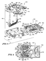
- Fig. 5 illustrates an exploded perspective view of another embodiment of the invention; and
- Fig. 6 illustrates a top plan view of the information carrier illustrated in Fig. 5.
- Referring to Fig. 1, an automatic reading
blood glucose meter 20 for reading test strips 22 onto which droplets of blood have been placed is illustrated. Technologies and procedures for the placement of blood droplets on the strips 22, timing the reaction of the glucose in the blood droplets, and removing the blood from the strips 22 to halt the reaction of the glucose with the chemistries with which the strips 22 are treated are all well known and will not be discussed in any greater detail here. Meters of the type of describedmeter 20 are also well known and will not be further discussed here except to mention an example of such meters, the model ACCU-CHEK® II meter available from Boehringer Mannheim Diagnostics, 9115 Hague Road, Indianapolis, Indiana 46250. -
Meter 20 includes aslot 24 into which a reacted test strip 22 is inserted for reading, adisplay 26 and one ormore buttons 28 which control the operation of themeter 20. The illustratedmeter 20 also includes asocket 30 including an opening 32 accessible through oneopen end 34 of thesocket 30 and into whichinformation carriers 36 can selectively be inserted longitudinally. As previously mentioned, it is contemplated that aninformation carrier 36 carrying meter 20-calibrating information pertinent to a particular package of test strips 22 will be provided with that package of test strips. As themeter 20 executes its program each time a test strip 22 from that particular package is read, the calibration information will be read from theinformation carrier 36 by themeter 20 to enhance the accuracy of themeter 20's displayed result. When that package of test strips 22 is exhausted, theinformation carrier 36 can be discarded or returned to the manufacturer for reprogramming. Anew information carrier 36 containing calibration information pertinent to a new package of test strips 22 will be provided with that new package of test strips 22. - The configurations of the
socket 30 andinformation carrier 36 are better illustrated in Figs. 2-3. Both are illustratively constructed from high-impact injection molded resins. Thesocket 30 is constructed of anupper portion 40 and alower portion 42.Upper portion 40 is provided with two diagonally extendingrows openings 50 each.Row 44 is angled generally toward acorner 52 ofupper portion 40 androw 46 is angled generally toward acorner 54 thereof. Eight substantially equal length, formed resilient wire,electrical contacts 56 includeportions 58 which extend throughrespective openings 50 andportions 60 which extend rearwardly generally longitudinally of thesocket 30, curving slightly downwardly and then upwardly adjacent theirdistal ends 62. Theportions 58 can be connected to circuitry withinmeter 20 at the points at which they extend from socketupper portion 40. At their intersection, eachportion contacts 56 are constructed, thedistal ends 62 ofportions 60 are biased generally transversely of the longitudinal extent ofsocket 30 towardlower portion 42. -
Lower portion 42 includes abottom wall 64 and two longitudinally extendingsidewalls 66 which extend perpendicularly upward from the oppositelongitudinal edges 68 ofbottom wall 64. The upper andlower portions socket 30 are joined byscrews 70 which project through openings provided therefor adjacent the corners ofupper portion 40 and into respective, aligned threaded holes in the top edges ofsidewalls 66. -
Information carrier 36 includes an eight conductor (four conductors per side edge) read-only-memory integratedcircuit chip 71 programmed with calibration information pertinent to a particular package of test strips.Chip 71 is mounted in acavity 72 provided therefor in theupper surface 74 ofcarrier 36.Carrier 36 also includesgrooves end wall 96 ofcarrier 36.Walls adjacent grooves Grooves surface 74 ofcarrier 36 generally along the same diagonals asrows upper portion 40. The leads 110, 112, 114, 116, 118, 120, 122, 124 ofchip 71 terminate ingrooves openings 126 being provided inwalls leads openings 128 being provided inwalls leads openings 130 being provided inwalls leads leads rows leads electrical contacts 56 and the ones ofleads respective contacts 56 are not to come into contact whencarrier 36 is inserted fully into its use orientation insocket 30. - The
outer end 140 ofcarrier 36 is provided with transversely extendinggrooves 142 which aid in gripping thecarrier 36, for example, between the thumb and forefinger of the user for insertion of thecarrier 36 into, and removal ofcarrier 36 from,socket 30.Semicircular cutouts 144 at the outer ends of upper andlower socket portions carrier 36 intosocket 30 upside down, afillet 146 is provided at the base of eachwall 66 oflower portion 42 wherewall 66 joinsbottom wall 64.Complementary chamfers 148 of a length sufficient to accommodatefillets 146 are provided along the bottom edges ofcarrier 36. The back orinner edge 150 ofupper portion 40 is provided with downwardly extendingtabs 152 which also help reduce the likelihood of overinsertion ofcarrier 36 intosocket 30. - Another configuration of the socket and information carrier is illustrated in Fig. 4. The
socket 230 is constructed of anupper portion 240 and alower portion 242.Upper portion 240 is provided with two diagonally extendingrows openings 250 each. Row 244 is angled generally toward acorner 252 ofupper portion 240 androw 246 is angled generally toward acorner 254 thereof. Eight substantially equal length, formed resilient wire,electrical contacts 256 of substantially the same configuration ascontacts 56 in the embodiment of Figs. 2-3 are mounted inrespective openings 250. -
Lower portion 242 includes abottom wall 264 and two longitudinally extendingsidewalls 266 which extend perpendicularly upward from the oppositelongitudinal edges 268 ofbottom wall 264. The upper andlower portions socket 230 are joined byscrews 270 which project through openings provided therefor adjacent the corners oflower portion 242 and into respective, aligned threaded holes in theupper portion 240. -
Information carrier 236 includes an eight conductor (four conductors per side edge) read-only-memory integratedcircuit chip 271 programmed with calibration information pertinent to a particular package of test strips.Chip 271 is mounted in acavity 272 provided therefor in theupper surface 274 ofcarrier 236.Carrier 236 also includesgrooves end wall 296 ofcarrier 236.Walls adjacent grooves Grooves surface 274 ofcarrier 236 generally along the same diagonals asrows upper portion 240. The leads 310, 312, 314, 316, 318, 320, 322, 324 ofchip 271 terminate ingrooves openings 326 being provided inwalls leads openings 328 being provided inwalls leads openings 330 being provided inwalls leads leads rows leads electrical contacts 256 and the ones ofleads respective contacts 256 are not to come into contact whencarrier 236 is inserted fully into its use orientation insocket 230. - The
outer end 340 ofcarrier 236 is provided with transversely extendinggrooves 342 which aid in gripping thecarrier 236, for example, between the thumb and forefinger of the user for insertion of thecarrier 236 into, and removal ofcarrier 236 from,socket 230. The back orinner edge 350 ofupper portion 240 is provided with a downwardly extendingtab 352 which helps reduce the likelihood of overinsertion ofcarrier 236 intosocket 230. - Referring to Figs. 5-6, a
socket 430 is constructed of anupper portion 440 and alower portion 442.Upper portion 440 is provided with two diagonally extendingrows openings 450 each. Row 444 is angled generally toward acorner 452 ofupper portion 440 androw 446 is angled generally toward a corner 454 thereof. Eight substantially equal length, formed resilient wire,electrical contacts 456 includeportions 458 which extend throughrespective openings 450 andportions 460 which extend rearwardly generally longitudinally of thesocket 430, and then extend upward adjacent theirdistal ends 462 through respective elongated, longitudinally extendingslots 463 provided inupper portion 440 ofsocket 430. Theportions 458 can be connected to circuitry within a meter at the points at which they extend from socketupper portion 440. At their intersection, eachportion contacts 456 are constructed, the distal ends 462 ofportions 460 are biased generally transversely of the longitudinal extent ofsocket 430 towardlower portion 442. -
Lower portion 442 includes a bottom wall 464 and two longitudinally extendingsidewalls 466 which extend perpendicularly upward from the oppositelongitudinal edges 468 of bottom wall 464. The upper andlower portions socket 430 are joined by ultrasonically welding them together atregions 470 ofupper portion 440 and along the top edges ofsidewalls 466. -
Information carrier 436 includes an eight conductor (four conductors per side edge) read-only-memory integratedcircuit chip 471 programmed with calibration information pertinent to a particular package of test strips.Chip 471 is mounted in acavity 472 provided therefor in theupper surface 474 ofcarrier 436.Carrier 436 also includesgrooves end wall 496 ofcarrier 436.Walls adjacent grooves Grooves carrier 436. The leads 510, 512, 514, 516, 518, 520, 522, 524 ofchip 471 terminate ingrooves walls leads openings 528 being provided inwalls leads openings 530 being provided inwalls leads Leads rows leads electrical contacts 456 and the ones ofleads respective contacts 456 are not to come into contact whencarrier 436 is inserted fully into its use orientation insocket 430. - The
outer end 540 ofcarrier 436 is provided with transversely extendingbosses 542 which aid in gripping thecarrier 436, for example, between the thumb and forefinger of the user for insertion of thecarrier 436 into, and removal ofcarrier 436 from,socket 430.Semicircular cutouts 544 at the outer ends of upper andlower socket portions carrier 436 intosocket 430 upside down, afillet 546 is provided at the base of eachwall 466 oflower portion 442 wherewall 466 joins bottom wall 464.Complementary chamfers 548 of a length sufficient to accommodatefillets 546 are provided along the bottom edges ofcarrier 436. The back orinner edge 550 ofupper portion 440 is provided with downwardly extendingtabs 552 which engage the inner ends 554 ofwalls carrier 436 intosocket 430. Aboss 556 which projects upwardly from the bottom wall 464 oflower portion 442 ofsocket 430 and acomplementary recess 558 on the underside 560 ofcarrier 436 near the inner end thereof help identify for the user when thecarrier 436 is in the use orientation. - It will thus be appreciated that, according to the invention, a standard multiple-sourced, commercially available integrated circuit is modified by automated machinery and inserted into a single, low-cost, mass producible, injection molded plastic carrier in such a manner as to provide electrostatic discharge protection, with the IC leads oriented for contact by a plurality of electrical contacts in a mating socket which typically is mounted on a printed circuit board.
- The information carrier package of the present invention is a single piece, low cost, mass producible, injection molded plastic part. Previous designs have utilized multiple parts, materials, and complex manufacturing processes. The integrated circuit used is packaged in an industry standard dual in-line package, which is installed in the carrier by means of a low cost method, for example, press-fitting, as opposed to the traditional solder-in-place method, or custom-manufactured integrated circuits. The carrier design affords electrostatic discharge protection to the IC, a feature not available in open contact designs, and at less cost and complexity than shutter-type devices. The capacity or function of the unit can be easily changed by installing a different IC into the carrier. Data transfer with the device is by means of the simplest digital interface, permitting its use in low-cost, portable, battery-operated instruments. The present invention provides direct contact between a chip and the meter I/O. Most of the prior art puts the chip on a printed circuit board which is in turn connected with the computer. The present invention provides wiping contact between the chip I/O and the meter I/O. The prior art mostly involves game cartridges or special program cartridges for hand-held computers. The program cartridges or game cartridges typically have male contacts on the edge of a printed circuit board which communicate with female contacts in the body of the game or computer. Normally, there is no direct contact between the chip and the computer. Most prior art techniques require the use of complex reading electronics such as optical or magnetic readers and correspondingly complex software algorithms. The information storage density with the present invention is higher than most competing technologies. These differences permit application of the device as a disposable information carrier, not previously realizable because of higher prior art costs.
Claims (9)
- An apparatus comprising an integrated circuit carrier (36) for carrying an integrated circuit (71)and a socket (30) for removeably receiving the carrier and through which electrical contact is made to the integrated circuit to provide communication with the integrated circuit when the carrier is inserted into its use orientation in the socket,the socket including an opening for slidably longitudinally receiving the carrier and a plurality of first electrical contacts (56) which extend longitudinally in the socket in the directions of relative motion of the socket and carrier as the carrier is slidably inserted into its use orientation in the socket and removed from the socket,the carrier including a plurality of second electrical contacts (110, 112, 114, 116, 118, 120, 122, 124),at least one of the socket and carrier also providing upstanding first wall portions (98, 100, 102, 104, 106, 108) extending generally in the longitudinal directions of relative movement between the carrier and the socket as the carrier is inserted into, and removed from the socket,said first wall portions lying generally between adjacent ones of said first electrical contacts when the carrier is fully inserted into a use orientation in the socket to promote separation of the first electrical contacts from each other during insertion of the carrier into, removal of the carrier from and while the carrier is in its use orientation in the socket,characterized in thatthe carrier includes second wall portions lying generally between adjacent ones of said second electrical contacts to reduce the likelihood of accidential contact between adjacent second electrical contacts and in thatsaid second electrical contacts extend generally transversely to said first electrical contacts (56).
- An apparatus according to claim 1, wherein the distal ends (62) of portions (60) of said first electrical contacts (56) are biased generally transversely of the direction in which the socket (30) longitudinally extends.
- An apparatus according to claim 1, wherein the apparatus is a meter to determine the concentration of a medically significant component of a biological fluid with a test chemistry and said integrated circuit (71) contains information relating to the test chemistry to calibrate the apparatus.
- An apparatus according to claim 3, further comprising a slot (24) into which a reacted test strip (22) is inserted for reading, a display (26) and one or more buttons (28) which control the operation of the meter (20).
- An apparatus according to claim 1, wherein said socket (30) and said integrated circuit carrier (36) are both injection molded pieces.
- An apparatus according to claim 1, wherein the rows (44, 46) of openings (50) which receive said first electrical contacts are trimmed in a diagonal pattern.
- An apparatus according to claim 1, wherein said second electrical contacts are trimmed in a diagonal pattern.
- An apparatus according to claim 1, wherein the integrated circuit carrier (36) is further provided with transversely extending grooves (142) which aid in gripping the carrier.
- An apparatus according to claim 1, wherein the socket is provided with fillets (146) and the carrier is provided with complementary chamfers (148) to prevent wrong insertion of the carrier.
Applications Claiming Priority (3)
| Application Number | Priority Date | Filing Date | Title |
|---|---|---|---|
| US313244 | 1989-02-21 | ||
| US07/313,244 US5053199A (en) | 1989-02-21 | 1989-02-21 | Electronically readable information carrier |
| PCT/US1990/000968 WO1990010236A1 (en) | 1989-02-21 | 1990-02-16 | Electronically readable information carrier |
Publications (3)
| Publication Number | Publication Date |
|---|---|
| EP0460074A1 EP0460074A1 (en) | 1991-12-11 |
| EP0460074A4 EP0460074A4 (en) | 1992-09-09 |
| EP0460074B1 true EP0460074B1 (en) | 1997-05-07 |
Family
ID=23214952
Family Applications (1)
| Application Number | Title | Priority Date | Filing Date |
|---|---|---|---|
| EP90904167A Expired - Lifetime EP0460074B1 (en) | 1989-02-21 | 1990-02-16 | Electronically readable information carrier |
Country Status (10)
| Country | Link |
|---|---|
| US (1) | US5053199A (en) |
| EP (1) | EP0460074B1 (en) |
| JP (1) | JP2897845B2 (en) |
| KR (1) | KR0154314B1 (en) |
| AT (1) | ATE152844T1 (en) |
| AU (1) | AU5189690A (en) |
| CA (1) | CA2010400C (en) |
| DE (1) | DE69030657T2 (en) |
| ES (1) | ES2100881T3 (en) |
| WO (1) | WO1990010236A1 (en) |
Families Citing this family (143)
| Publication number | Priority date | Publication date | Assignee | Title |
|---|---|---|---|---|
| EP0444396B2 (en) * | 1990-01-30 | 2000-11-02 | AMPHENOL-TUCHEL ELECTRONICS GmbH | Connection device for a Si-module |
| DE4041905A1 (en) * | 1990-12-27 | 1992-07-02 | Boehringer Mannheim Gmbh | TEST CARRIER ANALYSIS SYSTEM |
| JP3118552B2 (en) * | 1991-02-27 | 2000-12-18 | ロッシュ ダイアグノスティックス コーポレイション | Apparatus and method for analyzing body fluid |
| US5232668A (en) * | 1991-02-27 | 1993-08-03 | Boehringer Mannheim Corporation | Test strip holding and reading mechanism for a meter |
| JP3251583B2 (en) * | 1991-02-27 | 2002-01-28 | ロシュ ダイアグノスティックス コーポレーション | How to communicate with microcomputer controlled instruments |
| US5246858A (en) * | 1991-02-27 | 1993-09-21 | Boehringer Mannheim Corporation | Apparatus and method for analyzing a body fluid |
| US5215480A (en) * | 1991-03-25 | 1993-06-01 | General Electric Company | Electronic circuit interrupter with attached terminal connector block |
| US5330360A (en) * | 1992-08-21 | 1994-07-19 | The Whitaker Corporation | Memory card and connector therefor |
| US5371687A (en) * | 1992-11-20 | 1994-12-06 | Boehringer Mannheim Corporation | Glucose test data acquisition and management system |
| EP0702789B8 (en) * | 1993-06-08 | 2006-06-14 | Roche Diagnostics Operations, Inc. | Biosensing meter which detects proper electrode engagement and distinguishes sample and check strips |
| US5366609A (en) * | 1993-06-08 | 1994-11-22 | Boehringer Mannheim Corporation | Biosensing meter with pluggable memory key |
| US5352351A (en) * | 1993-06-08 | 1994-10-04 | Boehringer Mannheim Corporation | Biosensing meter with fail/safe procedures to prevent erroneous indications |
| US5522255A (en) | 1993-08-31 | 1996-06-04 | Boehringer Mannheim Corporation | Fluid dose, flow and coagulation sensor for medical instrument |
| EP0720439A4 (en) * | 1993-08-31 | 1997-09-24 | Boehringer Mannheim Corp | Power supply monitor and control for medical instrument |
| DE69430926T2 (en) * | 1993-08-31 | 2003-02-06 | Roche Diagnostics Corp | ANALOG HEATING CONTROL FOR A MEDICAL INSTRUMENT |
| US5526111A (en) * | 1993-08-31 | 1996-06-11 | Boehringer Mannheim Corporation | Method and apparatus for calculating a coagulation characteristic of a sample of blood a blood fraction or a control |
| US5841023A (en) * | 1993-08-31 | 1998-11-24 | Boehringer Mannheim Corporation | Magnet for medical instrument |
| US5690893A (en) * | 1994-06-10 | 1997-11-25 | Hitachi, Ltd. | Analyzer having sensor with memory device |
| FR2728709B1 (en) * | 1994-07-13 | 1997-01-24 | Schlumberger Ind Sa | PORTABLE INTERFACE FOR ELECTRONIC CHIP CARD |
| US5630986A (en) * | 1995-01-13 | 1997-05-20 | Bayer Corporation | Dispensing instrument for fluid monitoring sensors |
| US5714742A (en) * | 1995-05-10 | 1998-02-03 | Matsushita Electric Industrial Co., Ltd. | IC-card reader/writer for an IC-card |
| US6048734A (en) | 1995-09-15 | 2000-04-11 | The Regents Of The University Of Michigan | Thermal microvalves in a fluid flow method |
| US5665215A (en) * | 1995-09-25 | 1997-09-09 | Bayer Corporation | Method and apparatus for making predetermined events with a biosensor |
| US5838539A (en) * | 1995-11-08 | 1998-11-17 | Electronics Accessory Specialists International | Docking module for portable computers |
| US5989917A (en) * | 1996-02-13 | 1999-11-23 | Selfcare, Inc. | Glucose monitor and test strip containers for use in same |
| US5736103A (en) * | 1996-08-09 | 1998-04-07 | Lifescan, Inc. | Remote-dosing analyte concentration meter |
| GB2322444B (en) * | 1996-10-30 | 2000-01-19 | Mercury Diagnostics Inc | Synchronized analyte testing system |
| CA2547299C (en) | 1997-12-04 | 2009-03-03 | Roche Diagnostics Corporation | Instrument and method |
| US6009632A (en) * | 1997-12-12 | 2000-01-04 | Mercury Diagnostics, Inc. | Alignment system for optical analyte testing meter components |
| US8071384B2 (en) | 1997-12-22 | 2011-12-06 | Roche Diagnostics Operations, Inc. | Control and calibration solutions and methods for their use |
| US6830731B1 (en) * | 1998-01-05 | 2004-12-14 | Biosite, Inc. | Immunoassay fluorometer |
| US6074616A (en) * | 1998-01-05 | 2000-06-13 | Biosite Diagnostics, Inc. | Media carrier for an assay device |
| US6392894B1 (en) | 1998-01-05 | 2002-05-21 | Biosite Incorporated | Media carrier for an assay device |
| US7713703B1 (en) | 2000-11-13 | 2010-05-11 | Biosite, Inc. | Methods for monitoring the status of assays and immunoassays |
| US6194222B1 (en) | 1998-01-05 | 2001-02-27 | Biosite Diagnostics, Inc. | Methods for monitoring the status of assays and immunoassays |
| US8239627B2 (en) * | 2008-05-08 | 2012-08-07 | Lifenexus, Inc. | Smartcard accessed dual server electronic data storage system |
| US6602469B1 (en) * | 1998-11-09 | 2003-08-05 | Lifestream Technologies, Inc. | Health monitoring and diagnostic device and network-based health assessment and medical records maintenance system |
| CA2350145C (en) * | 1998-11-09 | 2005-02-08 | Lifestream Technologies, Inc. | Health monitoring and diagnostic device and network-based health assessment and medical records maintenance system |
| AU768312B2 (en) | 1998-11-30 | 2003-12-11 | Abbott Laboratories | Analyte test instrument having improved calibration and communication processes |
| US6773671B1 (en) | 1998-11-30 | 2004-08-10 | Abbott Laboratories | Multichemistry measuring device and test strips |
| US6285454B1 (en) * | 1998-12-07 | 2001-09-04 | Mercury Diagnostics, Inc. | Optics alignment and calibration system |
| US6270357B1 (en) * | 1999-05-06 | 2001-08-07 | Wayne K. Pfaff | Mounting for high frequency device packages |
| USD431527S (en) * | 1999-07-07 | 2000-10-03 | Mitsumi Electric Co., Ltd. | Distributor for electronic calculator |
| USD431525S (en) * | 1999-07-07 | 2000-10-03 | Mitsumi Electric Co., Ltd. | Distributor for electronic calculator |
| USD431811S (en) * | 1999-07-07 | 2000-10-10 | Mitsumi Electric Co., Ltd. | Distributor for electronic calculator |
| US6616819B1 (en) | 1999-11-04 | 2003-09-09 | Therasense, Inc. | Small volume in vitro analyte sensor and methods |
| US20060091006A1 (en) * | 1999-11-04 | 2006-05-04 | Yi Wang | Analyte sensor with insertion monitor, and methods |
| ATE278946T1 (en) * | 2000-03-22 | 2004-10-15 | All Medicus Co Ltd | ELECTROCHEMICAL BIOSENSOR TEST STRIP WITH DETECTION ELECTRODE AND READER USING THIS TEST STRIP |
| KR100767204B1 (en) * | 2000-03-28 | 2007-10-17 | 다이어베티스 다이어그노스틱스, 인크. | Continuous process for manufacture of disposable electro-chemical sensor |
| US6413213B1 (en) | 2000-04-18 | 2002-07-02 | Roche Diagnostics Corporation | Subscription based monitoring system and method |
| US6692700B2 (en) | 2001-02-14 | 2004-02-17 | Handylab, Inc. | Heat-reduction methods and systems related to microfluidic devices |
| US7192557B2 (en) | 2001-03-28 | 2007-03-20 | Handylab, Inc. | Methods and systems for releasing intracellular material from cells within microfluidic samples of fluids |
| US7323140B2 (en) | 2001-03-28 | 2008-01-29 | Handylab, Inc. | Moving microdroplets in a microfluidic device |
| US6852287B2 (en) | 2001-09-12 | 2005-02-08 | Handylab, Inc. | Microfluidic devices having a reduced number of input and output connections |
| US7270786B2 (en) | 2001-03-28 | 2007-09-18 | Handylab, Inc. | Methods and systems for processing microfluidic samples of particle containing fluids |
| US7010391B2 (en) | 2001-03-28 | 2006-03-07 | Handylab, Inc. | Methods and systems for control of microfluidic devices |
| US7829025B2 (en) | 2001-03-28 | 2010-11-09 | Venture Lending & Leasing Iv, Inc. | Systems and methods for thermal actuation of microfluidic devices |
| US8895311B1 (en) | 2001-03-28 | 2014-11-25 | Handylab, Inc. | Methods and systems for control of general purpose microfluidic devices |
| US6575188B2 (en) | 2001-07-26 | 2003-06-10 | Handylab, Inc. | Methods and systems for fluid control in microfluidic devices |
| ES2269717T3 (en) | 2001-06-08 | 2007-04-01 | Roche Diagnostics Gmbh | DEVICE OF EXTRACTION OF SAMPLES OF BODY FLUID AND CARTRIDGE WITH THE MEANS OF ANALYSIS TO BE USED WITH SUCH DEVICE. |
| US7018843B2 (en) | 2001-11-07 | 2006-03-28 | Roche Diagnostics Operations, Inc. | Instrument |
| US6743635B2 (en) * | 2002-04-25 | 2004-06-01 | Home Diagnostics, Inc. | System and methods for blood glucose sensing |
| US20080112852A1 (en) * | 2002-04-25 | 2008-05-15 | Neel Gary T | Test Strips and System for Measuring Analyte Levels in a Fluid Sample |
| US6946299B2 (en) * | 2002-04-25 | 2005-09-20 | Home Diagnostics, Inc. | Systems and methods for blood glucose sensing |
| AU2003234944A1 (en) * | 2002-08-27 | 2004-03-18 | Bayer Healthcare, Llc | Methods of Determining Glucose Concentration in Whole Blood Samples |
| US7572237B2 (en) | 2002-11-06 | 2009-08-11 | Abbott Diabetes Care Inc. | Automatic biological analyte testing meter with integrated lancing device and methods of use |
| US7118708B2 (en) * | 2002-11-12 | 2006-10-10 | Automated Biotechnology, Inc. | System of sample medium carriers with built-in memory elements and information input/output station for the carriers |
| US7731900B2 (en) | 2002-11-26 | 2010-06-08 | Roche Diagnostics Operations, Inc. | Body fluid testing device |
| US7175897B2 (en) * | 2002-12-17 | 2007-02-13 | Avery Dennison Corporation | Adhesive articles which contain at least one hydrophilic or hydrophobic layer, method for making and uses for same |
| US7582258B2 (en) | 2002-12-23 | 2009-09-01 | Roche Diagnostics Operations, Inc. | Body fluid testing device |
| KR100699214B1 (en) | 2002-12-23 | 2007-03-28 | 에프. 호프만-라 로슈 아게 | Body fluid testing device, test cassette, method of providing test medium, and method of analyzing body fluid |
| US7718439B2 (en) | 2003-06-20 | 2010-05-18 | Roche Diagnostics Operations, Inc. | System and method for coding information on a biosensor test strip |
| US8058077B2 (en) | 2003-06-20 | 2011-11-15 | Roche Diagnostics Operations, Inc. | Method for coding information on a biosensor test strip |
| US8206565B2 (en) | 2003-06-20 | 2012-06-26 | Roche Diagnostics Operation, Inc. | System and method for coding information on a biosensor test strip |
| US7645373B2 (en) | 2003-06-20 | 2010-01-12 | Roche Diagnostic Operations, Inc. | System and method for coding information on a biosensor test strip |
| US7488601B2 (en) | 2003-06-20 | 2009-02-10 | Roche Diagnostic Operations, Inc. | System and method for determining an abused sensor during analyte measurement |
| US7452457B2 (en) | 2003-06-20 | 2008-11-18 | Roche Diagnostics Operations, Inc. | System and method for analyte measurement using dose sufficiency electrodes |
| US8148164B2 (en) | 2003-06-20 | 2012-04-03 | Roche Diagnostics Operations, Inc. | System and method for determining the concentration of an analyte in a sample fluid |
| US7645421B2 (en) | 2003-06-20 | 2010-01-12 | Roche Diagnostics Operations, Inc. | System and method for coding information on a biosensor test strip |
| WO2005011867A2 (en) * | 2003-07-31 | 2005-02-10 | Handylab, Inc. | Processing particle-containing samples |
| ES2553097T3 (en) | 2004-05-03 | 2015-12-04 | Handylab, Inc. | Processing of samples containing polynucleotides |
| US8852862B2 (en) | 2004-05-03 | 2014-10-07 | Handylab, Inc. | Method for processing polynucleotide-containing samples |
| US20050283380A1 (en) * | 2004-06-18 | 2005-12-22 | Garduno Ramon S | Delivery service for a health management system |
| US7569126B2 (en) | 2004-06-18 | 2009-08-04 | Roche Diagnostics Operations, Inc. | System and method for quality assurance of a biosensor test strip |
| DE102004048864A1 (en) * | 2004-10-07 | 2006-04-13 | Roche Diagnostics Gmbh | Analytical test element with wireless data transmission |
| GB0509919D0 (en) * | 2005-05-16 | 2005-06-22 | Ralph Ellerker 1795 Ltd | Improvements to door closure system |
| US8016154B2 (en) * | 2005-05-25 | 2011-09-13 | Lifescan, Inc. | Sensor dispenser device and method of use |
| US8594943B2 (en) * | 2005-05-27 | 2013-11-26 | Bionime Gmbh | Coding module, a bio sensing meter and a system for operating a bio sensing meter |
| US20060290488A1 (en) * | 2005-05-27 | 2006-12-28 | Bionime Corporation | Coding module and sensing meter and system therefor |
| TWI265677B (en) | 2005-06-01 | 2006-11-01 | Bionime Corp | Coding module, bio measuring meter and system for operating bio measuring meter |
| CN101051045A (en) | 2006-02-24 | 2007-10-10 | 生命扫描苏格兰有限公司 | Usability methods of calibrating an analyte measurement meter using RFID |
| US8883490B2 (en) | 2006-03-24 | 2014-11-11 | Handylab, Inc. | Fluorescence detector for microfluidic diagnostic system |
| US8088616B2 (en) | 2006-03-24 | 2012-01-03 | Handylab, Inc. | Heater unit for microfluidic diagnostic system |
| US10900066B2 (en) | 2006-03-24 | 2021-01-26 | Handylab, Inc. | Microfluidic system for amplifying and detecting polynucleotides in parallel |
| US11806718B2 (en) | 2006-03-24 | 2023-11-07 | Handylab, Inc. | Fluorescence detector for microfluidic diagnostic system |
| WO2007112114A2 (en) | 2006-03-24 | 2007-10-04 | Handylab, Inc. | Integrated system for processing microfluidic samples, and method of using same |
| US7998708B2 (en) | 2006-03-24 | 2011-08-16 | Handylab, Inc. | Microfluidic system for amplifying and detecting polynucleotides in parallel |
| EP1839692B1 (en) * | 2006-03-30 | 2007-11-28 | Roche Diagnostics GmbH | Infusion system comprising an infusion unit and a remote control unit |
| US20080073208A1 (en) * | 2006-09-08 | 2008-03-27 | Chia-Nan Wang | Biosensor Requiring No Code Card |
| EP2091647A2 (en) | 2006-11-14 | 2009-08-26 | Handylab, Inc. | Microfluidic system for amplifying and detecting polynucleotides in parallel |
| US9052306B2 (en) * | 2007-03-23 | 2015-06-09 | Bionime Corporation | Coding module, bio measuring meter and system for operating bio measuring meter |
| US20080274552A1 (en) * | 2007-05-04 | 2008-11-06 | Brian Guthrie | Dynamic Information Transfer |
| US9186677B2 (en) | 2007-07-13 | 2015-11-17 | Handylab, Inc. | Integrated apparatus for performing nucleic acid extraction and diagnostic testing on multiple biological samples |
| US8182763B2 (en) | 2007-07-13 | 2012-05-22 | Handylab, Inc. | Rack for sample tubes and reagent holders |
| US20090136385A1 (en) | 2007-07-13 | 2009-05-28 | Handylab, Inc. | Reagent Tube |
| USD621060S1 (en) | 2008-07-14 | 2010-08-03 | Handylab, Inc. | Microfluidic cartridge |
| US8324372B2 (en) | 2007-07-13 | 2012-12-04 | Handylab, Inc. | Polynucleotide capture materials, and methods of using same |
| US9618139B2 (en) | 2007-07-13 | 2017-04-11 | Handylab, Inc. | Integrated heater and magnetic separator |
| US8105783B2 (en) | 2007-07-13 | 2012-01-31 | Handylab, Inc. | Microfluidic cartridge |
| US8287820B2 (en) | 2007-07-13 | 2012-10-16 | Handylab, Inc. | Automated pipetting apparatus having a combined liquid pump and pipette head system |
| US8133671B2 (en) | 2007-07-13 | 2012-03-13 | Handylab, Inc. | Integrated apparatus for performing nucleic acid extraction and diagnostic testing on multiple biological samples |
| PL2185939T3 (en) | 2007-09-01 | 2012-05-31 | Life Assays Ab | Disposable analytical microprocessor device |
| US8001825B2 (en) * | 2007-11-30 | 2011-08-23 | Lifescan, Inc. | Auto-calibrating metering system and method of use |
| TWI366137B (en) * | 2008-03-17 | 2012-06-11 | Health & Life Co Ltd | Biological sensing meter and data communicating method thereof |
| US20090246075A1 (en) * | 2008-03-25 | 2009-10-01 | Health & Life Co., Ltd. | Biosensing device |
| US20110200498A1 (en) * | 2008-06-17 | 2011-08-18 | Polymer Technology Systems, Inc. | System and method for packaging dry test strips |
| DE102008029715B4 (en) | 2008-06-23 | 2011-08-25 | Bionime Corporation, Taichung | Coding module, bio-meter and system for operating the bio-meter |
| USD618820S1 (en) | 2008-07-11 | 2010-06-29 | Handylab, Inc. | Reagent holder |
| USD787087S1 (en) | 2008-07-14 | 2017-05-16 | Handylab, Inc. | Housing |
| US20100051455A1 (en) * | 2008-08-26 | 2010-03-04 | Roche Diagnostics Operations, Inc. | Biosensor test strip cards |
| US20100198107A1 (en) | 2009-01-30 | 2010-08-05 | Roche Diagnostics Operations, Inc. | Integrated blood glucose meter and lancing device |
| US20100331652A1 (en) * | 2009-06-29 | 2010-12-30 | Roche Diagnostics Operations, Inc. | Modular diabetes management systems |
| US9218453B2 (en) * | 2009-06-29 | 2015-12-22 | Roche Diabetes Care, Inc. | Blood glucose management and interface systems and methods |
| DE102009038542A1 (en) | 2009-08-25 | 2011-03-03 | Health & Life Co., Ltd., Chung Ho | Biosensor measuring device for adjusting parameter of strip or test strip in measuring device, has input unit, which has parameter-adjusting card for test strip and interface for biosensor measuring device |
| EP2496303A4 (en) | 2009-11-04 | 2017-06-21 | Hygieia Inc. | Apparatus and methods for taking blood glucose measurements and recommending insulin doses |
| WO2012142516A1 (en) | 2011-04-15 | 2012-10-18 | Becton, Dickinson And Company | Scanning real-time microfluidic thermo-cycler and methods for synchronized thermocycling and scanning optical detection |
| USD692162S1 (en) | 2011-09-30 | 2013-10-22 | Becton, Dickinson And Company | Single piece reagent holder |
| ES2825905T3 (en) | 2011-09-30 | 2021-05-17 | Becton Dickinson Co | Unified test strip |
| WO2013067202A1 (en) | 2011-11-04 | 2013-05-10 | Handylab, Inc. | Polynucleotide sample preparation device |
| CN107881219B (en) | 2012-02-03 | 2021-09-10 | 贝克顿·迪金森公司 | External file for molecular diagnostic test assignment and compatibility determination between tests |
| US8920628B2 (en) | 2012-11-02 | 2014-12-30 | Roche Diagnostics Operations, Inc. | Systems and methods for multiple analyte analysis |
| JP6356707B2 (en) | 2013-03-15 | 2018-07-11 | エフ.ホフマン−ラ ロシュ アーゲーF. Hoffmann−La Roche Aktiengesellschaft | Method for detecting high antioxidant levels during electrochemical measurements and then fail-safe analyte concentration and devices, apparatus and systems incorporating the same |
| EP3388823A1 (en) | 2013-03-15 | 2018-10-17 | Roche Diabetes Care GmbH | Methods of scaling data used to construct biosensor algorithms as well as devices, apparatuses and systems incorporating the same |
| WO2014140172A1 (en) | 2013-03-15 | 2014-09-18 | Roche Diagnostics Gmbh | Methods of failsafing electrochemical measurements of an analyte as well as devices, apparatuses and systems incorporating the same |
| JP6352954B2 (en) | 2013-03-15 | 2018-07-04 | エフ.ホフマン−ラ ロシュ アーゲーF. Hoffmann−La Roche Aktiengesellschaft | Method and device for using information from recovery pulses in electrochemical analyte measurement, apparatus and system incorporating them |
| US20160088136A1 (en) * | 2014-09-24 | 2016-03-24 | Paolo Di Donato | Smartphone Based Meter and Injector |
| CA3123430A1 (en) | 2014-11-03 | 2016-05-12 | F. Hoffmann-La Roche Ag | Electrode arrangements for electrochemical test elements and methods of use thereof |
| WO2017015346A1 (en) * | 2015-07-20 | 2017-01-26 | Cornell University | Device and method for point-of-care diagnostics and antibiotic resistance identification, and applications thereof |
| KR102372113B1 (en) | 2016-10-05 | 2022-03-07 | 에프. 호프만-라 로슈 아게 | Detection reagents and electrode arrangements for multi-analyte diagnostic test elements, and methods of using the same |
| USD894898S1 (en) | 2019-03-26 | 2020-09-01 | Toast, Inc. | Card reader |
| US10733828B1 (en) | 2019-03-26 | 2020-08-04 | Toast, Inc. | Fixed point-of-sale terminal with configurable credit card device |
| US10755515B1 (en) | 2019-03-26 | 2020-08-25 | Toast, Inc. | Handheld point-of-sale terminal with configurable credit card device |
| US10748369B1 (en) * | 2019-03-26 | 2020-08-18 | Toast, Inc. | Configurable credit card device |
Family Cites Families (56)
| Publication number | Priority date | Publication date | Assignee | Title |
|---|---|---|---|---|
| GB796345A (en) * | 1955-06-03 | 1958-06-11 | Powers Samas Account Mach Ltd | Improvements in or relating to electrical connection boxes |
| US2879458A (en) * | 1957-10-30 | 1959-03-24 | Westinghouse Electric Corp | Diode matrix |
| US3297974A (en) * | 1965-04-15 | 1967-01-10 | Ind Electronic Hardware Corp | Receptacle for integrated circuit module |
| US3345541A (en) * | 1966-02-21 | 1967-10-03 | Amp Inc | Mounting and connecting means for circuit devices |
| US3517438A (en) * | 1966-05-12 | 1970-06-30 | Ibm | Method of packaging a circuit module and joining same to a circuit substrate |
| US3408612A (en) * | 1966-09-26 | 1968-10-29 | Sperry Rand Corp | Connector design |
| US3526480A (en) * | 1966-12-15 | 1970-09-01 | Xerox Corp | Automated chemical analyzer |
| US3551295A (en) * | 1967-11-29 | 1970-12-29 | Northrop Corp | Microbiological detection and identification system |
| US3701077A (en) * | 1969-12-29 | 1972-10-24 | Tech Inc K | Electronic components |
| US3832969A (en) * | 1970-03-02 | 1974-09-03 | Becton Dickinson Co | Blood test system |
| US3745509A (en) * | 1971-03-02 | 1973-07-10 | Bunker Ramo | High density electrical connector |
| US3771109A (en) * | 1972-05-01 | 1973-11-06 | Bunker Ramo | Electrical connector for integrated circuit device |
| US3868526A (en) * | 1973-07-02 | 1975-02-25 | Burroughs Corp | Display panel |
| US3932132A (en) * | 1973-07-31 | 1976-01-13 | Olympus Optical Co., Ltd. | System for detecting the particular chemical constituent of a fluid |
| US3999827A (en) * | 1975-10-10 | 1976-12-28 | Burroughs Corporation | Electrical connector for semiconductor device package |
| US4023879A (en) * | 1975-10-20 | 1977-05-17 | A.P. Products Incorporated | Adjustable electrical connector with replaceable contact sub-assembly and variable strain relief |
| US4035046A (en) * | 1976-01-15 | 1977-07-12 | Amp Incorporated | Miniature electrical connector for parallel panel members |
| US4327953A (en) * | 1977-06-06 | 1982-05-04 | Texas Instruments Incorporated | Interchangeable module for integrated circuits |
| US4216522A (en) * | 1977-06-06 | 1980-08-05 | Texas Instruments Incorporated | Interchangeable module for integrated circuits |
| US4179178A (en) * | 1978-02-02 | 1979-12-18 | Rca Corporation | Plug-in circuit cartridge with electrostatic charge protection |
| US4329642A (en) * | 1979-03-09 | 1982-05-11 | Siliconix, Incorporated | Carrier and test socket for leadless integrated circuit |
| US4297569A (en) * | 1979-06-28 | 1981-10-27 | Datakey, Inc. | Microelectronic memory key with receptacle and systems therefor |
| US4326125A (en) * | 1980-06-26 | 1982-04-20 | Datakey, Inc. | Microelectronic memory key with receptacle and systems therefor |
| US4464832A (en) * | 1981-05-14 | 1984-08-14 | Amp Incorporated | Method of making cartridge connector system |
| US4406508A (en) * | 1981-07-02 | 1983-09-27 | Thomas & Betts Corporation | Dual-in-line package assembly |
| US4379966A (en) * | 1981-07-23 | 1983-04-12 | Datakey, Inc. | Receptacle for electronic information key |
| US4465898A (en) * | 1981-07-27 | 1984-08-14 | Texas Instruments Incorporated | Carrier for integrated circuit |
| DE3137174A1 (en) * | 1981-09-18 | 1983-04-07 | Boehringer Mannheim Gmbh, 6800 Mannheim | DEVICE FOR THE OPTICAL DETECTION OF A CODING ON A DIAGNOSTIC TEST STRIP |
| US4436993A (en) * | 1982-01-11 | 1984-03-13 | Datakey, Inc. | Electronic key |
| US4506938A (en) * | 1982-07-06 | 1985-03-26 | At&T Bell Laboratories | Integrated circuit chip carrier mounting arrangement |
| US4490001A (en) * | 1983-02-07 | 1984-12-25 | Matsushita Electric Industrial Co., Ltd. | Dip carrier and socket |
| US4491378A (en) * | 1983-02-28 | 1985-01-01 | Amp Incorporated | Zero insertion force electrical connector |
| US4480835A (en) * | 1983-03-02 | 1984-11-06 | Williams Theodore R | Cartridge adapter for programmable video games |
| US4620088A (en) * | 1983-03-02 | 1986-10-28 | Datakey, Inc. | Receptacle design for use with electronic key-like device |
| US4659915A (en) * | 1983-03-02 | 1987-04-21 | Datakey, Inc. | Receptacle design for use with electronic key-like device |
| US4578573A (en) * | 1983-03-23 | 1986-03-25 | Datakey, Inc. | Portable electronic information devices and method of manufacture |
| US4549076A (en) * | 1983-03-24 | 1985-10-22 | Datakey, Inc. | Orientation guide arrangement for electronic key and receptacle combination |
| DE3326689A1 (en) * | 1983-07-23 | 1985-01-31 | Boehringer Mannheim Gmbh, 6800 Mannheim | METHOD AND DEVICE FOR PRODUCING A TEST STRIP |
| US4522456A (en) * | 1984-01-25 | 1985-06-11 | Datakey, Inc. | Electronic tag receptacle and reader |
| US4538867A (en) * | 1984-02-17 | 1985-09-03 | Thomas & Betts Corporation | Socket assembly connector for an electrical component |
| DE3584532D1 (en) * | 1984-02-27 | 1991-12-05 | Amp Inc | CONTACT FOR CIRCUIT CARRIER AND METHOD FOR INSERTING IT IN A HOUSING. |
| US4598962A (en) * | 1984-03-14 | 1986-07-08 | Motorola, Inc. | Memory device retaining apparatus for portable data processor |
| US4609240A (en) * | 1984-05-01 | 1986-09-02 | The United States Of America As Represented By The Secretary Of The Army | Cabinet mounted printed circuit board electrical connector |
| US4549036A (en) * | 1984-07-23 | 1985-10-22 | Reichbach Morris M | Circular integrated circuit package |
| US4648665A (en) * | 1984-10-16 | 1987-03-10 | Amp Incorporated | Electronic key assemblies |
| US4560218A (en) * | 1984-12-03 | 1985-12-24 | Amp Incorporated | Socket for surface mount dip |
| US4564251A (en) * | 1984-12-13 | 1986-01-14 | Itt Corporation | Leadless chip carrier adapter |
| US4623208A (en) * | 1985-04-03 | 1986-11-18 | Wells Electronic, Inc. | Leadless chip carrier socket |
| JPH0218545Y2 (en) * | 1985-10-02 | 1990-05-23 | ||
| US4714874A (en) * | 1985-11-12 | 1987-12-22 | Miles Inc. | Test strip identification and instrument calibration |
| US4652067A (en) * | 1985-12-06 | 1987-03-24 | Switchcraft, Inc. | Electrical connector with an internal switch |
| JPH0615273B2 (en) * | 1986-01-20 | 1994-03-02 | 株式会社アイテイテイキャノン | IC card |
| US4766520A (en) * | 1986-12-05 | 1988-08-23 | Capsonic Group, Inc. | Injection molded circuit housing |
| JPH039267Y2 (en) * | 1986-12-27 | 1991-03-07 | ||
| US4752679A (en) * | 1987-03-02 | 1988-06-21 | Datakey, Inc. | Receptacle device |
| US4776520A (en) * | 1987-05-11 | 1988-10-11 | Binks Manufacturing Company | Rotary atomizer |
-
1989
- 1989-02-21 US US07/313,244 patent/US5053199A/en not_active Expired - Lifetime
-
1990
- 1990-02-16 DE DE69030657T patent/DE69030657T2/en not_active Expired - Lifetime
- 1990-02-16 ES ES90904167T patent/ES2100881T3/en not_active Expired - Lifetime
- 1990-02-16 AU AU51896/90A patent/AU5189690A/en not_active Abandoned
- 1990-02-16 EP EP90904167A patent/EP0460074B1/en not_active Expired - Lifetime
- 1990-02-16 WO PCT/US1990/000968 patent/WO1990010236A1/en active IP Right Grant
- 1990-02-16 KR KR1019900702291A patent/KR0154314B1/en not_active IP Right Cessation
- 1990-02-16 AT AT90904167T patent/ATE152844T1/en not_active IP Right Cessation
- 1990-02-16 JP JP2504406A patent/JP2897845B2/en not_active Expired - Lifetime
- 1990-02-20 CA CA002010400A patent/CA2010400C/en not_active Expired - Lifetime
Also Published As
| Publication number | Publication date |
|---|---|
| EP0460074A4 (en) | 1992-09-09 |
| CA2010400C (en) | 1996-10-22 |
| KR0154314B1 (en) | 1998-12-01 |
| AU5189690A (en) | 1990-09-26 |
| JPH04506721A (en) | 1992-11-19 |
| JP2897845B2 (en) | 1999-05-31 |
| DE69030657T2 (en) | 1997-09-11 |
| US5053199A (en) | 1991-10-01 |
| DE69030657D1 (en) | 1997-06-12 |
| KR910700465A (en) | 1991-03-15 |
| CA2010400A1 (en) | 1990-08-21 |
| EP0460074A1 (en) | 1991-12-11 |
| WO1990010236A1 (en) | 1990-09-07 |
| ATE152844T1 (en) | 1997-05-15 |
| ES2100881T3 (en) | 1997-07-01 |
Similar Documents
| Publication | Publication Date | Title |
|---|---|---|
| EP0460074B1 (en) | Electronically readable information carrier | |
| US8388906B2 (en) | Apparatus for dispensing test strips | |
| JP4282946B2 (en) | Instrument | |
| US8388905B2 (en) | Method and apparatus for coding diagnostic meters | |
| US8394328B2 (en) | Test strip container with integrated meter having strip coding capability | |
| US4765344A (en) | Blood transfer assembly | |
| US7896704B2 (en) | Strip connectors for measurement devices | |
| EP0724226B1 (en) | IC card reader/writer | |
| JPH09274976A (en) | Electric connector for contact type card | |
| JPWO2002059831A1 (en) | IC card and IC card adapter device | |
| US20060271307A1 (en) | Coding module, a bio sensing meter and a system for operating a bio sensing meter | |
| US9052306B2 (en) | Coding module, bio measuring meter and system for operating bio measuring meter | |
| JP2001356108A (en) | Biosensor | |
| US4580001A (en) | Packaging device for electronic component | |
| EP1228477B1 (en) | Connector devices |
Legal Events
| Date | Code | Title | Description |
|---|---|---|---|
| PUAI | Public reference made under article 153(3) epc to a published international application that has entered the european phase |
Free format text: ORIGINAL CODE: 0009012 |
|
| AK | Designated contracting states |
Kind code of ref document: A1 Designated state(s): AT BE CH DE DK ES FR GB IT LI LU NL SE |
|
| A4 | Supplementary search report drawn up and despatched |
Effective date: 19920723 |
|
| AK | Designated contracting states |
Kind code of ref document: A4 Designated state(s): AT BE CH DE DK ES FR GB IT LI LU NL SE |
|
| 17P | Request for examination filed |
Effective date: 19910816 |
|
| 17Q | First examination report despatched |
Effective date: 19940303 |
|
| GRAG | Despatch of communication of intention to grant |
Free format text: ORIGINAL CODE: EPIDOS AGRA |
|
| GRAH | Despatch of communication of intention to grant a patent |
Free format text: ORIGINAL CODE: EPIDOS IGRA |
|
| GRAH | Despatch of communication of intention to grant a patent |
Free format text: ORIGINAL CODE: EPIDOS IGRA |
|
| GRAA | (expected) grant |
Free format text: ORIGINAL CODE: 0009210 |
|
| AK | Designated contracting states |
Kind code of ref document: B1 Designated state(s): AT BE CH DE DK ES FR GB IT LI LU NL SE |
|
| PG25 | Lapsed in a contracting state [announced via postgrant information from national office to epo] |
Ref country code: NL Free format text: LAPSE BECAUSE OF FAILURE TO SUBMIT A TRANSLATION OF THE DESCRIPTION OR TO PAY THE FEE WITHIN THE PRESCRIBED TIME-LIMIT Effective date: 19970507 Ref country code: AT Effective date: 19970507 Ref country code: DK Effective date: 19970507 Ref country code: CH Effective date: 19970507 Ref country code: BE Effective date: 19970507 Ref country code: LI Effective date: 19970507 |
|
| REF | Corresponds to: |
Ref document number: 152844 Country of ref document: AT Date of ref document: 19970515 Kind code of ref document: T |
|
| REG | Reference to a national code |
Ref country code: CH Ref legal event code: EP |
|
| REF | Corresponds to: |
Ref document number: 69030657 Country of ref document: DE Date of ref document: 19970612 |
|
| ET | Fr: translation filed | ||
| REG | Reference to a national code |
Ref country code: ES Ref legal event code: FG2A Ref document number: 2100881 Country of ref document: ES Kind code of ref document: T3 |
|
| PG25 | Lapsed in a contracting state [announced via postgrant information from national office to epo] |
Ref country code: SE Effective date: 19970807 |
|
| NLV1 | Nl: lapsed or annulled due to failure to fulfill the requirements of art. 29p and 29m of the patents act | ||
| REG | Reference to a national code |
Ref country code: CH Ref legal event code: PL |
|
| PG25 | Lapsed in a contracting state [announced via postgrant information from national office to epo] |
Ref country code: LU Free format text: LAPSE BECAUSE OF NON-PAYMENT OF DUE FEES Effective date: 19980216 |
|
| PLBE | No opposition filed within time limit |
Free format text: ORIGINAL CODE: 0009261 |
|
| STAA | Information on the status of an ep patent application or granted ep patent |
Free format text: STATUS: NO OPPOSITION FILED WITHIN TIME LIMIT |
|
| 26N | No opposition filed | ||
| REG | Reference to a national code |
Ref country code: GB Ref legal event code: IF02 |
|
| REG | Reference to a national code |
Ref country code: GB Ref legal event code: 732E |
|
| REG | Reference to a national code |
Ref country code: FR Ref legal event code: CD Ref country code: FR Ref legal event code: TP |
|
| PGFP | Annual fee paid to national office [announced via postgrant information from national office to epo] |
Ref country code: ES Payment date: 20090216 Year of fee payment: 20 |
|
| PGFP | Annual fee paid to national office [announced via postgrant information from national office to epo] |
Ref country code: DE Payment date: 20090227 Year of fee payment: 20 |
|
| PGFP | Annual fee paid to national office [announced via postgrant information from national office to epo] |
Ref country code: GB Payment date: 20090106 Year of fee payment: 20 |
|
| PGFP | Annual fee paid to national office [announced via postgrant information from national office to epo] |
Ref country code: IT Payment date: 20090213 Year of fee payment: 20 |
|
| PGFP | Annual fee paid to national office [announced via postgrant information from national office to epo] |
Ref country code: FR Payment date: 20090206 Year of fee payment: 20 |
|
| REG | Reference to a national code |
Ref country code: GB Ref legal event code: PE20 Expiry date: 20100215 |
|
| REG | Reference to a national code |
Ref country code: ES Ref legal event code: FD2A Effective date: 20100217 |
|
| PG25 | Lapsed in a contracting state [announced via postgrant information from national office to epo] |
Ref country code: GB Free format text: LAPSE BECAUSE OF EXPIRATION OF PROTECTION Effective date: 20100215 |
|
| PG25 | Lapsed in a contracting state [announced via postgrant information from national office to epo] |
Ref country code: ES Free format text: LAPSE BECAUSE OF EXPIRATION OF PROTECTION Effective date: 20100217 |
|
| PG25 | Lapsed in a contracting state [announced via postgrant information from national office to epo] |
Ref country code: DE Free format text: LAPSE BECAUSE OF EXPIRATION OF PROTECTION Effective date: 20100216 |