EP0456281A2 - Dynamic mechanical bonding method and apparatus - Google Patents
Dynamic mechanical bonding method and apparatus Download PDFInfo
- Publication number
- EP0456281A2 EP0456281A2 EP91112103A EP91112103A EP0456281A2 EP 0456281 A2 EP0456281 A2 EP 0456281A2 EP 91112103 A EP91112103 A EP 91112103A EP 91112103 A EP91112103 A EP 91112103A EP 0456281 A2 EP0456281 A2 EP 0456281A2
- Authority
- EP
- European Patent Office
- Prior art keywords
- nip
- laminae
- nip defining
- members
- patterned
- Prior art date
- Legal status (The legal status is an assumption and is not a legal conclusion. Google has not performed a legal analysis and makes no representation as to the accuracy of the status listed.)
- Granted
Links
Images
Classifications
-
- B—PERFORMING OPERATIONS; TRANSPORTING
- B29—WORKING OF PLASTICS; WORKING OF SUBSTANCES IN A PLASTIC STATE IN GENERAL
- B29C—SHAPING OR JOINING OF PLASTICS; SHAPING OF MATERIAL IN A PLASTIC STATE, NOT OTHERWISE PROVIDED FOR; AFTER-TREATMENT OF THE SHAPED PRODUCTS, e.g. REPAIRING
- B29C66/00—General aspects of processes or apparatus for joining preformed parts
- B29C66/40—General aspects of joining substantially flat articles, e.g. plates, sheets or web-like materials; Making flat seams in tubular or hollow articles; Joining single elements to substantially flat surfaces
- B29C66/41—Joining substantially flat articles ; Making flat seams in tubular or hollow articles
- B29C66/45—Joining of substantially the whole surface of the articles
-
- A—HUMAN NECESSITIES
- A44—HABERDASHERY; JEWELLERY
- A44B—BUTTONS, PINS, BUCKLES, SLIDE FASTENERS, OR THE LIKE
- A44B18/00—Fasteners of the touch-and-close type; Making such fasteners
- A44B18/0003—Fastener constructions
- A44B18/0011—Female or loop elements
-
- A—HUMAN NECESSITIES
- A61—MEDICAL OR VETERINARY SCIENCE; HYGIENE
- A61F—FILTERS IMPLANTABLE INTO BLOOD VESSELS; PROSTHESES; DEVICES PROVIDING PATENCY TO, OR PREVENTING COLLAPSING OF, TUBULAR STRUCTURES OF THE BODY, e.g. STENTS; ORTHOPAEDIC, NURSING OR CONTRACEPTIVE DEVICES; FOMENTATION; TREATMENT OR PROTECTION OF EYES OR EARS; BANDAGES, DRESSINGS OR ABSORBENT PADS; FIRST-AID KITS
- A61F13/00—Bandages or dressings; Absorbent pads
- A61F13/15—Absorbent pads, e.g. sanitary towels, swabs or tampons for external or internal application to the body; Supporting or fastening means therefor; Tampon applicators
- A61F13/56—Supporting or fastening means
- A61F13/62—Mechanical fastening means, ; Fabric strip fastener elements, e.g. hook and loop
-
- B—PERFORMING OPERATIONS; TRANSPORTING
- B29—WORKING OF PLASTICS; WORKING OF SUBSTANCES IN A PLASTIC STATE IN GENERAL
- B29C—SHAPING OR JOINING OF PLASTICS; SHAPING OF MATERIAL IN A PLASTIC STATE, NOT OTHERWISE PROVIDED FOR; AFTER-TREATMENT OF THE SHAPED PRODUCTS, e.g. REPAIRING
- B29C65/00—Joining or sealing of preformed parts, e.g. welding of plastics materials; Apparatus therefor
- B29C65/02—Joining or sealing of preformed parts, e.g. welding of plastics materials; Apparatus therefor by heating, with or without pressure
- B29C65/18—Joining or sealing of preformed parts, e.g. welding of plastics materials; Apparatus therefor by heating, with or without pressure using heated tools
-
- B—PERFORMING OPERATIONS; TRANSPORTING
- B29—WORKING OF PLASTICS; WORKING OF SUBSTANCES IN A PLASTIC STATE IN GENERAL
- B29C—SHAPING OR JOINING OF PLASTICS; SHAPING OF MATERIAL IN A PLASTIC STATE, NOT OTHERWISE PROVIDED FOR; AFTER-TREATMENT OF THE SHAPED PRODUCTS, e.g. REPAIRING
- B29C66/00—General aspects of processes or apparatus for joining preformed parts
- B29C66/01—General aspects dealing with the joint area or with the area to be joined
- B29C66/05—Particular design of joint configurations
- B29C66/10—Particular design of joint configurations particular design of the joint cross-sections
- B29C66/11—Joint cross-sections comprising a single joint-segment, i.e. one of the parts to be joined comprising a single joint-segment in the joint cross-section
- B29C66/112—Single lapped joints
- B29C66/1122—Single lap to lap joints, i.e. overlap joints
-
- B—PERFORMING OPERATIONS; TRANSPORTING
- B29—WORKING OF PLASTICS; WORKING OF SUBSTANCES IN A PLASTIC STATE IN GENERAL
- B29C—SHAPING OR JOINING OF PLASTICS; SHAPING OF MATERIAL IN A PLASTIC STATE, NOT OTHERWISE PROVIDED FOR; AFTER-TREATMENT OF THE SHAPED PRODUCTS, e.g. REPAIRING
- B29C66/00—General aspects of processes or apparatus for joining preformed parts
- B29C66/01—General aspects dealing with the joint area or with the area to be joined
- B29C66/05—Particular design of joint configurations
- B29C66/20—Particular design of joint configurations particular design of the joint lines, e.g. of the weld lines
- B29C66/21—Particular design of joint configurations particular design of the joint lines, e.g. of the weld lines said joint lines being formed by a single dot or dash or by several dots or dashes, i.e. spot joining or spot welding
-
- B—PERFORMING OPERATIONS; TRANSPORTING
- B29—WORKING OF PLASTICS; WORKING OF SUBSTANCES IN A PLASTIC STATE IN GENERAL
- B29C—SHAPING OR JOINING OF PLASTICS; SHAPING OF MATERIAL IN A PLASTIC STATE, NOT OTHERWISE PROVIDED FOR; AFTER-TREATMENT OF THE SHAPED PRODUCTS, e.g. REPAIRING
- B29C66/00—General aspects of processes or apparatus for joining preformed parts
- B29C66/80—General aspects of machine operations or constructions and parts thereof
- B29C66/81—General aspects of the pressing elements, i.e. the elements applying pressure on the parts to be joined in the area to be joined, e.g. the welding jaws or clamps
- B29C66/814—General aspects of the pressing elements, i.e. the elements applying pressure on the parts to be joined in the area to be joined, e.g. the welding jaws or clamps characterised by the design of the pressing elements, e.g. of the welding jaws or clamps
- B29C66/8141—General aspects of the pressing elements, i.e. the elements applying pressure on the parts to be joined in the area to be joined, e.g. the welding jaws or clamps characterised by the design of the pressing elements, e.g. of the welding jaws or clamps characterised by the surface geometry of the part of the pressing elements, e.g. welding jaws or clamps, coming into contact with the parts to be joined
- B29C66/81433—General aspects of the pressing elements, i.e. the elements applying pressure on the parts to be joined in the area to be joined, e.g. the welding jaws or clamps characterised by the design of the pressing elements, e.g. of the welding jaws or clamps characterised by the surface geometry of the part of the pressing elements, e.g. welding jaws or clamps, coming into contact with the parts to be joined being toothed, i.e. comprising several teeth or pins, or being patterned
-
- B—PERFORMING OPERATIONS; TRANSPORTING
- B29—WORKING OF PLASTICS; WORKING OF SUBSTANCES IN A PLASTIC STATE IN GENERAL
- B29C—SHAPING OR JOINING OF PLASTICS; SHAPING OF MATERIAL IN A PLASTIC STATE, NOT OTHERWISE PROVIDED FOR; AFTER-TREATMENT OF THE SHAPED PRODUCTS, e.g. REPAIRING
- B29C66/00—General aspects of processes or apparatus for joining preformed parts
- B29C66/80—General aspects of machine operations or constructions and parts thereof
- B29C66/82—Pressure application arrangements, e.g. transmission or actuating mechanisms for joining tools or clamps
- B29C66/824—Actuating mechanisms
- B29C66/8242—Pneumatic or hydraulic drives
-
- B—PERFORMING OPERATIONS; TRANSPORTING
- B29—WORKING OF PLASTICS; WORKING OF SUBSTANCES IN A PLASTIC STATE IN GENERAL
- B29C—SHAPING OR JOINING OF PLASTICS; SHAPING OF MATERIAL IN A PLASTIC STATE, NOT OTHERWISE PROVIDED FOR; AFTER-TREATMENT OF THE SHAPED PRODUCTS, e.g. REPAIRING
- B29C66/00—General aspects of processes or apparatus for joining preformed parts
- B29C66/80—General aspects of machine operations or constructions and parts thereof
- B29C66/83—General aspects of machine operations or constructions and parts thereof characterised by the movement of the joining or pressing tools
- B29C66/834—General aspects of machine operations or constructions and parts thereof characterised by the movement of the joining or pressing tools moving with the parts to be joined
- B29C66/8341—Roller, cylinder or drum types; Band or belt types; Ball types
- B29C66/83411—Roller, cylinder or drum types
-
- B—PERFORMING OPERATIONS; TRANSPORTING
- B29—WORKING OF PLASTICS; WORKING OF SUBSTANCES IN A PLASTIC STATE IN GENERAL
- B29C—SHAPING OR JOINING OF PLASTICS; SHAPING OF MATERIAL IN A PLASTIC STATE, NOT OTHERWISE PROVIDED FOR; AFTER-TREATMENT OF THE SHAPED PRODUCTS, e.g. REPAIRING
- B29C66/00—General aspects of processes or apparatus for joining preformed parts
- B29C66/80—General aspects of machine operations or constructions and parts thereof
- B29C66/83—General aspects of machine operations or constructions and parts thereof characterised by the movement of the joining or pressing tools
- B29C66/834—General aspects of machine operations or constructions and parts thereof characterised by the movement of the joining or pressing tools moving with the parts to be joined
- B29C66/8351—Jaws mounted on rollers, cylinders, drums, bands, belts or chains; Flying jaws
- B29C66/83511—Jaws mounted on rollers, cylinders, drums, bands, belts or chains; Flying jaws jaws mounted on rollers, cylinders or drums
-
- B—PERFORMING OPERATIONS; TRANSPORTING
- B29—WORKING OF PLASTICS; WORKING OF SUBSTANCES IN A PLASTIC STATE IN GENERAL
- B29C—SHAPING OR JOINING OF PLASTICS; SHAPING OF MATERIAL IN A PLASTIC STATE, NOT OTHERWISE PROVIDED FOR; AFTER-TREATMENT OF THE SHAPED PRODUCTS, e.g. REPAIRING
- B29C66/00—General aspects of processes or apparatus for joining preformed parts
- B29C66/90—Measuring or controlling the joining process
- B29C66/92—Measuring or controlling the joining process by measuring or controlling the pressure, the force, the mechanical power or the displacement of the joining tools
- B29C66/924—Measuring or controlling the joining process by measuring or controlling the pressure, the force, the mechanical power or the displacement of the joining tools by controlling or regulating the pressure, the force, the mechanical power or the displacement of the joining tools
- B29C66/9241—Measuring or controlling the joining process by measuring or controlling the pressure, the force, the mechanical power or the displacement of the joining tools by controlling or regulating the pressure, the force, the mechanical power or the displacement of the joining tools by controlling or regulating the pressure, the force or the mechanical power
-
- B—PERFORMING OPERATIONS; TRANSPORTING
- B29—WORKING OF PLASTICS; WORKING OF SUBSTANCES IN A PLASTIC STATE IN GENERAL
- B29C—SHAPING OR JOINING OF PLASTICS; SHAPING OF MATERIAL IN A PLASTIC STATE, NOT OTHERWISE PROVIDED FOR; AFTER-TREATMENT OF THE SHAPED PRODUCTS, e.g. REPAIRING
- B29C66/00—General aspects of processes or apparatus for joining preformed parts
- B29C66/90—Measuring or controlling the joining process
- B29C66/92—Measuring or controlling the joining process by measuring or controlling the pressure, the force, the mechanical power or the displacement of the joining tools
- B29C66/929—Measuring or controlling the joining process by measuring or controlling the pressure, the force, the mechanical power or the displacement of the joining tools characterized by specific pressure, force, mechanical power or displacement values or ranges
-
- B—PERFORMING OPERATIONS; TRANSPORTING
- B29—WORKING OF PLASTICS; WORKING OF SUBSTANCES IN A PLASTIC STATE IN GENERAL
- B29C—SHAPING OR JOINING OF PLASTICS; SHAPING OF MATERIAL IN A PLASTIC STATE, NOT OTHERWISE PROVIDED FOR; AFTER-TREATMENT OF THE SHAPED PRODUCTS, e.g. REPAIRING
- B29C66/00—General aspects of processes or apparatus for joining preformed parts
- B29C66/90—Measuring or controlling the joining process
- B29C66/93—Measuring or controlling the joining process by measuring or controlling the speed
- B29C66/934—Measuring or controlling the joining process by measuring or controlling the speed by controlling or regulating the speed
- B29C66/93411—Measuring or controlling the joining process by measuring or controlling the speed by controlling or regulating the speed the parts to be joined having different speeds
-
- B—PERFORMING OPERATIONS; TRANSPORTING
- B29—WORKING OF PLASTICS; WORKING OF SUBSTANCES IN A PLASTIC STATE IN GENERAL
- B29C—SHAPING OR JOINING OF PLASTICS; SHAPING OF MATERIAL IN A PLASTIC STATE, NOT OTHERWISE PROVIDED FOR; AFTER-TREATMENT OF THE SHAPED PRODUCTS, e.g. REPAIRING
- B29C66/00—General aspects of processes or apparatus for joining preformed parts
- B29C66/90—Measuring or controlling the joining process
- B29C66/93—Measuring or controlling the joining process by measuring or controlling the speed
- B29C66/934—Measuring or controlling the joining process by measuring or controlling the speed by controlling or regulating the speed
- B29C66/93451—Measuring or controlling the joining process by measuring or controlling the speed by controlling or regulating the speed by controlling or regulating the rotational speed, i.e. the speed of revolution
-
- B—PERFORMING OPERATIONS; TRANSPORTING
- B29—WORKING OF PLASTICS; WORKING OF SUBSTANCES IN A PLASTIC STATE IN GENERAL
- B29C—SHAPING OR JOINING OF PLASTICS; SHAPING OF MATERIAL IN A PLASTIC STATE, NOT OTHERWISE PROVIDED FOR; AFTER-TREATMENT OF THE SHAPED PRODUCTS, e.g. REPAIRING
- B29C66/00—General aspects of processes or apparatus for joining preformed parts
- B29C66/90—Measuring or controlling the joining process
- B29C66/93—Measuring or controlling the joining process by measuring or controlling the speed
- B29C66/939—Measuring or controlling the joining process by measuring or controlling the speed characterised by specific speed values or ranges
-
- B—PERFORMING OPERATIONS; TRANSPORTING
- B29—WORKING OF PLASTICS; WORKING OF SUBSTANCES IN A PLASTIC STATE IN GENERAL
- B29C—SHAPING OR JOINING OF PLASTICS; SHAPING OF MATERIAL IN A PLASTIC STATE, NOT OTHERWISE PROVIDED FOR; AFTER-TREATMENT OF THE SHAPED PRODUCTS, e.g. REPAIRING
- B29C66/00—General aspects of processes or apparatus for joining preformed parts
- B29C66/01—General aspects dealing with the joint area or with the area to be joined
- B29C66/344—Stretching or tensioning the joint area during joining
-
- B—PERFORMING OPERATIONS; TRANSPORTING
- B29—WORKING OF PLASTICS; WORKING OF SUBSTANCES IN A PLASTIC STATE IN GENERAL
- B29C—SHAPING OR JOINING OF PLASTICS; SHAPING OF MATERIAL IN A PLASTIC STATE, NOT OTHERWISE PROVIDED FOR; AFTER-TREATMENT OF THE SHAPED PRODUCTS, e.g. REPAIRING
- B29C66/00—General aspects of processes or apparatus for joining preformed parts
- B29C66/70—General aspects of processes or apparatus for joining preformed parts characterised by the composition, physical properties or the structure of the material of the parts to be joined; Joining with non-plastics material
- B29C66/71—General aspects of processes or apparatus for joining preformed parts characterised by the composition, physical properties or the structure of the material of the parts to be joined; Joining with non-plastics material characterised by the composition of the plastics material of the parts to be joined
-
- B—PERFORMING OPERATIONS; TRANSPORTING
- B29—WORKING OF PLASTICS; WORKING OF SUBSTANCES IN A PLASTIC STATE IN GENERAL
- B29C—SHAPING OR JOINING OF PLASTICS; SHAPING OF MATERIAL IN A PLASTIC STATE, NOT OTHERWISE PROVIDED FOR; AFTER-TREATMENT OF THE SHAPED PRODUCTS, e.g. REPAIRING
- B29C66/00—General aspects of processes or apparatus for joining preformed parts
- B29C66/70—General aspects of processes or apparatus for joining preformed parts characterised by the composition, physical properties or the structure of the material of the parts to be joined; Joining with non-plastics material
- B29C66/72—General aspects of processes or apparatus for joining preformed parts characterised by the composition, physical properties or the structure of the material of the parts to be joined; Joining with non-plastics material characterised by the structure of the material of the parts to be joined
- B29C66/729—Textile or other fibrous material made from plastics
-
- B—PERFORMING OPERATIONS; TRANSPORTING
- B29—WORKING OF PLASTICS; WORKING OF SUBSTANCES IN A PLASTIC STATE IN GENERAL
- B29L—INDEXING SCHEME ASSOCIATED WITH SUBCLASS B29C, RELATING TO PARTICULAR ARTICLES
- B29L2024/00—Articles with hollow walls
-
- B—PERFORMING OPERATIONS; TRANSPORTING
- B29—WORKING OF PLASTICS; WORKING OF SUBSTANCES IN A PLASTIC STATE IN GENERAL
- B29L—INDEXING SCHEME ASSOCIATED WITH SUBCLASS B29C, RELATING TO PARTICULAR ARTICLES
- B29L2031/00—Other particular articles
- B29L2031/48—Wearing apparel
- B29L2031/4871—Underwear
- B29L2031/4878—Diapers, napkins
-
- Y—GENERAL TAGGING OF NEW TECHNOLOGICAL DEVELOPMENTS; GENERAL TAGGING OF CROSS-SECTIONAL TECHNOLOGIES SPANNING OVER SEVERAL SECTIONS OF THE IPC; TECHNICAL SUBJECTS COVERED BY FORMER USPC CROSS-REFERENCE ART COLLECTIONS [XRACs] AND DIGESTS
- Y10—TECHNICAL SUBJECTS COVERED BY FORMER USPC
- Y10T—TECHNICAL SUBJECTS COVERED BY FORMER US CLASSIFICATION
- Y10T156/00—Adhesive bonding and miscellaneous chemical manufacture
- Y10T156/17—Surface bonding means and/or assemblymeans with work feeding or handling means
- Y10T156/1702—For plural parts or plural areas of single part
- Y10T156/1712—Indefinite or running length work
- Y10T156/1737—Discontinuous, spaced area, and/or patterned pressing
Abstract
Description
- The invention pertains to methods of and apparatus for autogeniously (ie, without adhesives) laminating plural layers or laminae of sheet material together, at least one layer of which is thermoplastic film or web or non-woven or the like. It is, however, not intended to thereby limit the invention to precluding adhesive augmentation of such autogenious laminating.
- Laminated Sheet Material And Methods Of Making Such Material are disclosed in U. S. Patent 3,530,023 which issued September 22, 1970 to R. W. Schutte et al. As disclosed, such material comprises at least two adjacent layers of cellulosic fiber sheet material, and a layer of thermoplastic material which layers are secured together at a plurality of bonding areas by heat and pressure without the addition of any adhesive material. This patent states that such bonding may be achieved by forwarding the layers through a nip between two rolls which rolls are arranged to maintain a fixed spacial relationship relative to each other. As further disclosed, one of the rolls may be smooth surfaced with the other having spaced projections extending outwardly from its cylindrical surface; or both rolls may have such projections. Bonding areas of a size of from about 0.0005 to about 0.002 square inches (from about 0.003 to about 0.013 square centimeters) are said to be preferred.
- A non-woven structure, method and apparatus for producing non-wovens is disclosed in U. S. Patent 4,035,219 which issued July 12, 1977 to David Charles Cumbers. In this apparatus as disclosed, a thermoplastic non-woven is first formed as by extruding the thermoplastic from a spinneret; and then passing the filamentary mass through bonding means. In the bonding means, a bonding member such as a roll is provided which has projections on it; the bonding member is heated to a temperature below the softening point of the thermoplastic to be bonded, and the bonding member is pressure biased towards a backing member such as a roll; and the material to be bonded is passed therebetween. For example, through the nip between a pair of pressure biased nip rollers: a heated pattern roller having projections; and a backing roller. Bonding is said to be effected by virtue of the work done by the pressure biased, heated projections to compress the material. Projections having areas of from about 0.00001 to about 0.0005 square inches (from about 0.00006 to about 0.003 square centimeters) are stated to be preferred albeit projections having areas of up to about 0.001 square inches (about 0.006 square centimeters) are claimed.
- While prior art laminating apparatuses and methods for laminating web materials together have addressed some of the problems of achieving such lamination in the absence of adhesives, they have not addressed the problems to the extent of or in the manner of the present invention. For example, and without intending to thereby limit the scope of the present invention, providing an apparatus wherein laminating is achieved through the use of pressure biased laminating rolls which are operated with a predetermined surface velocity differential between them as provided by one aspect of the present invention; and providing an apparatus having heated, velocity matched laminating members having pattern elements having areas of greater than 0.002 square inches (about 0.013 square centimetres) which apparatus is particularly useful at intermediate and high level velocities as is provided by another aspect of the present invention.
- The invention provides, in one aspect, a method of dynamically bonding plural laminae together, at least one of which laminae comprises thermoplastic material, comprising the steps of forwarding said laminae with portions thereof in face to face relation, through a pressure biassed nip between a relief patterned nip defining member having pattern element segments, and a nip defining anvil member, said nip defining members being biassed towards each other with a predetermined pattern-element loading;wherein the method comprises driving said nip defining members to provide a predetermined surface velocity differential therebetween, in the range of from 2 to 40 percent of the surface velocity of said nip defining member having the lower surface velocity.
- Preferably, the nip defining anvil member is smooth surfaced; and is operated at a surface velocity that is greater than the surface velocity of the patterned nip defining member. More preferably, the surface velocity differential is in the range of from about 2 to about 20 percent.
- In another aspect of the invention, an apparatus is provided for carrying out the above method of dynamically bonding plural laminae together said apparatus comprising a relief patterned nip defining member and a nip defining anvil member, means for mounting said nip defining members to define a nip therebetween through which nip said laminae may be forwarded with portions thereof in face to face relation, means for controllably biassing said nip defining members towards each other, and means for driving said nip defining members
characterised in that said driving means is adapted to provide differential surface velocities within a range of from 2 to 40 percent of the surface velocity of said nip defining member having the lower surface velocity. - The method may further comprise the step of heating each of the nip defining members to a surface temperature that is a predetermined number of degrees below the melt temperature of the thermoplastic lamina disposed closest to it as the laminae are forwarded through the nip between the nip defining members.
- Preferably, the apparatus further comprises means for independently heating the nip defining members so that the surface temperature of each is within a predetermined range below the melt temperature of whichever lamina of the laminae that comprises thermoplastic material is disposed closest to each respective nip defining member as the laminae are forwarded through the nip defined by the nip defining members.
- A method of operating the above apparatus for dynamically bonding plural laminae together is also provided which assures bonds of high structural integrity in the absence of tearing and the like while assuring longevity of the pattern elements of its patterned nip defining member. Essentially this method entails operating one of the nip defining members at a predetermined velocity, e.g. a predetermined line speed in a converting apparatus. Then adjusting the velocity of the other nip defining member and the level of pressure biassing of the nip defining members towards each other to determine an operating point (i.e. a desired line velocity at a given velocity differential between the nip defining members and at a given level of nip pressure biassing) at which satisfactory autogenious bonding can be achieved at a level of nip pressuring biassing substantially lower than would be required in the absence of a velocity differential between the nip defining members. Preferably, the operating point for each line speed will be at a sufficiently high differential velocity to enable operating at a non-deleterious level of nip biassing pressure to achieve satisfactory bonding, i.e. strong bonding in the absence of a deleterious tearing or perforating of the laminae. However, at intermediate and high line velocities, operating points may be realized at zero velocity differential, i.e. with the nip defining members having equal surface velocities. Generally speaking, non-deleterious levels of nip biassing pressures are pressures below the yield strength of the pattern elements of patterned nip defining members and the like. Such biassing levels assure substantial useful life of the patterns elements disposed on the patterned nip defining member.
- While the specification concludes with claims which particularly point out and distinctly claim the subject matter regarded as forming the present invention, it is believed that the invention will be better understood from the following description taken in conjunction with the accompanying drawings in which:
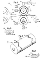
- Figure 1 is a fragmentary, somewhat schematic side elevational view of an exemplary apparatus embodiment of the present invention.
- Figure 2 is a perspective view of the patterned cylinder of the bonding apparatus shown in Figure 1.
- Figure 3 is an enlarged scale, fragmentary view looking radially inwardly toward a pattern element - a bonding lug - which is disposed on the cylindrical surface of the patterned cylinder shown in Figure 2.
- Figure 4 is a fragmentary sectional view taken along section line 4-4 of Figure 3.
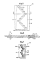
- Figure 5 is an enlarged scale, fragmentary plan view of two laminae having overlapping edge portions bonded together through the use of the present invention.
- Figure 6 is a somewhat schematic, fragmentary sectional view taken along section line 6-6 of Figure 5.
- Figure 7 is an enlarged scale, fragmentary plan view that is similar to Figure 5 but wherein a different pattern of bonds is shown for lap bonding edge portions of two laminae together through the use of the present invention.
- A somewhat schematic, fragmentary side elevational view of a dynamic
mechanical bonding apparatus 20 which is an embodiment of the present invention is shown in Figure 1.Apparatus 20 comprises: patternedcylinder 22;anvil cylinder 24; means 26 for adjustably biasingcylinders cylinders heating cylinders laminate 45 are also shown in Figure 1. Additionally,apparatus 20 comprises a frame, not shown; and means, not shown, fordriving rolls 31 through 38 for controllably forwardinglaminae nip 43 defined betweencylinder 22 andcylinder 24, and for enabling forwarding the resulting laminate --laminate 45--to downstream apparatus such as a roll winder or web converting apparatus: for example, a disposable diaper converter. - For clarity of the present invention, neither the upstream ends or sources of
laminae laminate 45 are shown. However, for example, it is well known to provide laminae of thermoplastic films, and paper and other webs in roll form; and to provide upstream unwinding and splicing means to enable forwarding continuous lengths of such laminae through laminating means and or converters to make products comprising laminated and/or other web elements at controlled velocities and under controlled tension. - Parenthetically, for simplicity and clarity of the invention,
apparatus 20 is described herein as comprisingcylinders - Briefly, referring to
apparatus 20, Figure 1, the present invention enables thermolaminating certain laminae together --providing at least one of the laminae comprises sufficient thermoplastic material that is susceptible to being thermobonded to the other laminae -- by forwarding the laminae together through a pressure biased nip between a patterned cylinder and an anvil cylinder which cylinders have a predetermined surface velocity difference between them. Such laminating can be effected at substantially lower nip biasing pressure (ie, substantially lower psi loadings on the pattern elements of the patterned cylinder) than if the cylinders are operated at equal surface velocities. Directionally, the greater the surface velocity differential, the lower the required nip biasing pressure. However, too great a surface velocity differential may precipitate tearing of the laminae, or the formation of unwanted holes or perforations therein so should preferably be avoided. Additionally, such laminating may be effected with even lower nip biasing pressure if one or both of the cylinders is heated: preferably to temperatures which are sufficiently lower than the melting points of the laminae that the laminae will not melt or stick to the laminating cylinders in the event, for example, the apparatus is temporarily stopped. - Referring now to Figure 2, patterned
cylinder 22 is configured to have a circularcylindrical surface 52, and a plurality of protuberances orpattern elements 51 which extend outwardly fromsurface 52. The protuberances are disposed in a predetermined pattern: each pattern element being configured and disposed to precipitate a bond site in the laminate being produced to effect a predetermined pattern of bond sites in the laminate. As shown in Figure 2,cylinder 22 has a saw-tooth shape pattern ofprotuberances 51 which extend circumferentially about each end of the cylinder. Such a cylinder is configured, for example, to laminate or lap-seam together a relatively narrow perforated web to each machine direction side edge of an imperforate web or thermoplastic film to form a backsheet for a disposable diaper having breathable side edges. Fragmentary side edge portions of exemplary such lap-seamed laminates comprising laminae having overlapping side edges are illustrated in Figures 5, 6 and 7 albeit neither lamina is shown to be perforated in those figures. In an exemplary embodiment of the invention,cylinder 22 is steel, and has a diameter of about 11.4 inches (about 29 cm.). -
Anvil cylinder 24, Figure 1, is preferably a smooth surfaced, right circular cylinder of steel. In an exemplary embodiment of the invention,anvil cylinder 24 has a 4.5 inch (about 11.4 cm.) diameter, and is independently power rotated by a speed controlled direct current motor. - Means 26, Figure 1, for biasing patterned
cylinder 22 towardsanvil cylinder 24 comprises pressure regulating means 55, and pneumatic actuator means 56. Pressure regulating means 55 is adapted to have its inlet connected to a supply source P of pressurized air, and to have its outlet connected to pneumatic actuator means 56 in order to adjust and control the pneumatic actuator means loading ofcylinders - Drive means 28, and drive means 29, Figure 1, are provided to independently drive
cylinders cylinder 22 is driven by the converter line drive through a gear train so that its surface velocity is essentially matched to the line velocity of the converter; and, as stated above,anvil cylinder 24 is powered by an independently speed controlled DC (direct current) drive. This enables adjusting the surface velocity of the anvil cylinder to be equal to, or less than, or greater than the surface velocity of the patterned cylinder by predetermined amounts or percentages. - Temperature control means 30a and 30b, Figure 1, are provided to adjustably control the surface temperatures of
cylinders cylinders cylinders -
Rolls 31 through 38, inclusive, are provided for guiding and advancing webs orlaminae ad laminate 45 through and away from nip 43. Preferably these rolls are driven at surface velocities which maintain predetermined levels of tension or stretch so that neither slack web conditions nor excessively tensioned/stretched webs and or laminate precipitate undesirable deleterious consequences. For example, in an exemplary disposable diaper converter comprising the present invention, rolls 31 through 38, andcylinder 22 are driven through gear trains and the like from the main converter drive to provide a nominal draw of about one percent in the lengths ofwebs laminate 45 being forwarded from nip 43 by the S-wrap drive rolls 37 and 38. - Turning now to Figure 3, a fragmentary portion of
cylinder 22 is shown which comprises onepattern element 51 disposed oncylindrical surface 52. Figure 4, a fragmentary sectional view taken along section line 4-4 of Figure 3, shows that thepattern element 51 is an integral portion ofcylinder 22, has substantially vertical side surfaces, and projects radially outwardly a distance H: ie, the radial height of the pattern element. While such an integral relationship is preferred, it is not intended to thereby limit the present invention to such integral constructions. In anexemplary apparatus 20,pattern element 51 has an oval planform having a width of about 0.055 inch (about 0.14 cm.), length of about 0.086 inch (about 0.22 cm.), end radii of about 0.0275 inch (about 0.07 cm.), end areas of about 0.004 square inches (about 0.026 square centimeters) and are oriented on the surface ofcylinder 22 with their width dimensions extending circumferentially. Starting with a right circular cylinder,pattern elements 51 were machined by removing surrounding metal by electric discharge machining to a depth of from about 0.015 to about 0.020 inch (about 0.4 mm to about 0.5 mm). Additionally, they were spaced -- center to center -- about 0.0/0 inch circumferentially (ie, in the machine direction), and about 0.072 inch laterally (ie, in the cross machine direction). A variation of such an element has a slightly chamfered edge: ie, about 0.010 inch wide edge portion beveled at about forty-five degrees. - Figure 5 is a plan view of a fragmentary portion of
laminate 45, Figure 1, comprising overlapping edge portions oflaminae pattern cylinder 22, Figure 2. For clarity, the machine direction oriented edges oflaminae - Figure 6, is a somewhat schematic, fragmentary sectional view taken along section line 6-6 of Figure 5, which illustratively shows a bond site 51b which thermobonds
laminae laminate 45. As shown, the bond site 51b has a bottom surface 51bb; substantiallyvertical side walls web 41 than the bottom surface 51bb is recessed from the bottom surface ofweb 42. While not wishing to be bound by a theory of operations, it is believed that such recessing on the pattern-element side oflaminate 45 may be precipitated by thepattern elements 51 displacing portions of the laminae per se; and the recessing on the anvil facing side of the laminate may be precipitated by cooling and removal of compressive forces uponlaminate 45 upon its issuing from nip 43. Figure 1. Indeed, in some lamina, portions of bond sites may even protrude rather than being recessed. - Figure 7, a plan view of a fragmentary portion of an
alternate laminate 145 made in accordance with the present invention.Laminate 145 is different fromlaminate 45 inasmuch as the zig zag pattern of bond sites oflaminate 145 comprises only 3 bond sites per leg whereas the pattern oflaminate 45, Figure 5, comprises 5 bond sites per leg; and the bond sites oflaminate 145 were precipitated by pattern elements similar topattern elements 51, Figure 4, but for having sloped sides rather than vertical sides. Thus, each bond site 151b oflaminate 145 has tapered or filletedside walls 151f. - An exemplary embodiment of
apparatus 20, Figure 1, comprising the exemplary elements described above was operated as follows to make sample laminates comprising overlapping side edge portions of two thermoplastic laminae. - A first set of samples -- samples 1a, 1b, 1c, 1d, and 1e --comprising identical polyethylene laminae having nominal thicknesses of about one-and-two-tenths mil (about 0.03 mm), and melt temperatures of about 225 degrees Fahrenheit (about 107 degrees Celcius) were run at a constant line velocity of about four-hundred-fifty feet per minute (about 137 meters per minute); and with both nip defining cylinders heated to provide surface temperatures of about one-hundred-sixty degrees Fahrenheit (about 73 degrees Celcius). Four different anvil cylinder surface velocities were set: minus five, zero, five, ten, and twenty percent faster than the patterned cylinder/line velocity. At each differential velocity condition, the nip biasing pressure was adjusted to precipitate bonds having about equal nominal peel strengths. The results are tabulated in TABLE 1. Note that nip biasing air pressure (ie, the pressure adjusted by
regulator 55, Figure 1) values are included as well as calculated nominal pattern element loadings in pounds per square inch (psi). Without intending to thereby limit the present invention, it is believed that the relative values of pressure (ie, their differences) manifest a principal benefit of the invention: that substantially lower pressures can be used in combination with greater velocity differentials to achieve bonds having approximately the same nominal peel strengths. This benefit translates, of course, into substantially longer pattern element lives.
Generally speaking, TABLE 1 illustrates that nip biasing pressure and differential velocity are inversely related. That is, all other things being equal, nip biasing pressure may be reduced as differential velocity is increased. Thus, nip biasing pressure may be set at values below the yield point of the pattern elements to assure relatively long operating lives for the pattern elements. - A second set of samples -- samples 2a, 2b, 2c, and 2d --were run using the same laminae as for sample Set No. 1 at constant nip biasing cylinder pressure of about 40 psi (ie, a calculated pattern element value of about 90,000 psi); and with the cylinders still heated to one-hundred-sixty degrees Fahrenheit. At four selected line velocities, the velocity differential was adjusted to precipitate bonds having about equal nominal peel strengths. The resulting data are tabulated in TABLE 2.

Generally speaking, TABLE 2 illustrates that line velocity and differential velocity are inversely related. That is, all other things being equal, as line speed increases, lower or no differential velocity is required to achieve a given nominal level of bond peel strength. Additionally, while peel strength data were taken in grams per inch units, only relative values are listed in the tables inasmuch as different test methodologies may precipitate different values. - A third set of samples -- Samples 3a, 3b, 3c, 3d, and 3e --were laminated from the same laminae as Sample Sets 1 and 2 above, using zero differential velocity, and heating both nip defining cylinders to about one-hundred-eighty degrees Fahrenheit (about 82 degrees Celcius). Five values of line velocity were set; then, the nip biasing pressure was adjusted to precipitate bonds having about equal nominal peel strengths. The resulting data are tabulated in TABLE 3.

Generally speaking, these data illustrate that -- in the absence of differential velocity between the nip defining cylinders -- the amount of nip biasing pressure required decreases as line velocity increases: particularly above three-hundred feet per minute (about 91.4 meters per minute); and, more particularly, at and above about four-hundred-fifty feet per minute (about 137 meters per minute). - Reflecting back to TABLES 1, 2 and 3, they essentially resulted from exploring three parameters two at a time: nip biasing pressure, velocity differential between the defining cylinders, and line velocity. Another important variable with respect to this invention is the temperature(s) to which the surfaces of the nip defining members (ie, their surfaces) are heated. Generally speaking all other things being equal, as cylinder temperature is increased from ambient towards the melting temperature of the thermoplastic lamina disposed closest to or in contact with the cylinder, bonds of increasing strength will be realized up to a point; and further increases in cylinder temperatures will produce, bonds of lesser strength. In general, cylinder surface temperatures in the range of from about forty to about one-hundred degrees Fahrenheit below the melt temperature of the lamina disposed closest to or in contact with each respective nip defining cylinder produce high strength bonds, and without precipitating holes in the laminae. Directionally, optimum cylinder surface temperatures are inversely related to line velocity: higher cylinder temperatures being preferred at relatively slow line velocities, and lower cylinder temperatures being preferred at relatively high line velocities. Thus, for example, with the identical laminae (both polyethylene having a melting temperature of about two-hundred-twenty-five degrees Fahrenheit) as utilized for Sample Sets 1, 2, and 3, satisfactory bond strengths--all other things being equal--were achieved at cylinder temperatures of about one hundred-forty degrees Fahrenheit (about 60 degrees Celcius) at a line velocity of about six-hundred feet per minute (about 183 meters per minute). When one lamina was replaced with a higher melting point polyethylene--a film having a melting point of about two-hundred-fifty-seven degrees Fahrenheit (about 125 degrees Celcius)--comparable strength bonds were achieved by heating the cylinder in contact with that lamina to a temperature of about one-hundred-seventy degrees Fahrenheit (about 77 degrees Celcius).
- While not wishing to be bound by a theory of operation, it is believed that differential velocity--when used--contributes shear energy to enable dynamic, mechanically induced, thermobonding. This is in addition to heat generated from molecular flow/fluid friction as bond-site thermoplastic is quickly displaced by the intrusion of pattern elements into the thermoplastic laminae. Additionally, inasmuch as effective bonding of webs or laminae occurs when they are at room ambient temperature going into the nip, it is believed that heating the nip defining members (eg,
cylinders 22 and 24) acts more to retard heat flow from the bond sites rather than being a source of heat flow into the bond sites. Moreover, inasmuch as maximum bond strengths are normally achieved at cylinder temperatures well below the melt temperatures of the laminae, it in believed that bonds made at higher temperatures do not wholly set as the laminate is forwarded from the bonding nip. Indeed, at high line speeds, good bonding may be achieved without heating the cylinders; ie, having the cylinders at room ambient temperature. - While specific examples have been described above, generally speaking, velocity differentials in the range of from about 2 to about 40 percent are preferred; from about 2 to about 20 percent are more preferred; and the surface velocity of the anvil cylinder is preferably greater than the pattern cylinder albeit it is not intended to thereby limit the present invention. Additionally, while it is preferred that the anvil cylinder have a smooth cylindrical surface, it is also not intended to thereby limit the invention to a laminating apparatus comprising a smooth surfaced anvil cylinder. Moreover, while the invention has been discussed above through the use of two laminae in continuous length web forms, it is not intended to thereby limit the invention to either continuous laminae or to two laminae. That is, discontinuous discrete lengths of lamina can also be laminated through application of this invention; and, of course, greater than two laminae may be laminated through application of this invention.
- Referring back to Figure 4,
pattern element 51 is shown to have a height H. Generally speaking, bond sites of minimum thickness are obtained when H is greater than the sum of the thicknesses of the laminae being laminated: eg, the sum of the thicknesses oflaminae - While particular embodiments of the present invention have been illustrated and described, it would be obvious to those skilled in the art that various other changes and modifications can be made without departing from the spirit and scope of the invention. It is, therefore, intended to cover in the appended claims all such changes and modifications that are within the scope of this invention.
Claims (12)
- A method of operating an apparatus for dynamically bonding plural laminae (41,42) together, at least one of which laminae comprises thermoplastic material, said apparatus comprising a patterned nip defining member (22) having pattern element segments (51) and a nip defining anvil member (24), means for mounting said nip defining members (22,24) to define a nip therebetween through which nip said laminae (41,42) may be forwarded with portions thereof in face to face relation, means (26) for controllably biassing said nip defining members towards each other, means (28,29) for driving said nip defining members (22,24) to provide predetermined surface velocities, and means for heating at least one of said nip defining members, said method comprising the steps of:
driving one of said nip defining members (22,24) at a predetermined first surface velocity; and
forwarding said laminae (41,42) with portions thereof in face to face relation through said nip, said nip defining members being biassed towards each other with a predetermined pattern-element loading;
characterised in that the method comprises interactively driving the other of said nip defining members (22,24) to provide a sufficient surface velocity differential relative to said first surface velocity, in combination with a substantially non-deleterious level of said biassing, to effect dynamic thermal bonding of said laminae while obviating deleterious tearing or perforation of said laminae. - A method according to Claim 1 wherein said laminae are forwarded at a velocity of at least 91.4 metres per minute, said pattern element segments (51) comprise discrete projections having tip surface areas greater than 0.013 square centimetres and said predetermined pattern-element loading is no more than 62 x 10⁴ kPa.
- A method according to either one of Claims 1 & 2 further comprising the step of adjusting and controlling the surface temperature of each said nip defining member at an elevated predetermined surface temperature to augment the dynamic thermobonding of said laminae.
- A method according to any of the preceding claims wherein said patterned nip defining member (22) is rotatably mounted and is driven at said surface velocity which is essentially matched to the forwarding velocity of said laminae (41,42) throught said nip (43).
- A method according to any one of the preceding claims wherein said nip defining anvil member (24) is rotatably mounted, and comprises smooth surface portions for opposing said pattern elements (51), said surface portions being circular cylindrical sectors.
- A method according to any of the preceding claims wherein said nip defining anvil member (24) is driven with a greater surface velocity than said patterned nip defining member (22).
- An apparatus for carrying out a method of dynamically bonding plural laminae together according to any one of claims 1-5, said apparatus comprising a relief patterned nip defining member (22) and a nip defining anvil member (24), means for mounting said nip defining members to define a nip (43) therebetween, through which nip said laminae (41,42) may be forwarded with portions thereof in face to face relation, means (55,56) for controllably biassing said nip defining members towards each other, and means (28,29) for driving said nip defining members (22,24), characterised in that each of said driving means (28,29) is independent and is adapted to provide differential surface velocities to said nip defining members.
- An apparatus according to claim 7 further comprising means (30a, 30b) for independently controlling the surface temperatures of said nip defining members (22,24) whereby each said nip defining member may be operated so that its surface temperature is within a predetermined range of the melt temperature of whichever lamina of said laminae (41,42) that comprises thermoplastic material is disposed closest to each respective said nip defining member as said laminae are forwarded through said nip.
- An apparatus according to either one of claims 7 or 8 wherein said patterned nip defining member (22) comprises pattern element segments (51), and said nip defining anvil member (24) is rotatably mounted and comprises smooth surface portions for opposing said pattern element segments, said surface portions being circular cylindrical sectors.
- An apparatus according to any one of claims 6 to 8 wherein said patterned nip defining member (22) is a rotatably mounted component comprising a circular cylindrical sector (52) having pattern element segments (51) disposed thereon.
- An apparatus according to any one of claims 6 to 9 wherein said patterned nip defining member (22) comprises pattern element segments (51) having heights that are greater than the sum of the thicknesses of said laminae.
- An apparatus according to any one of claims 6 to 9 wherein said patterned nip defining member (22) comprises pattern element segments (51) having heights that are about equal to or less than the sum of the thicknesses of said laminae, thereby to precipitate bond sites having predetermined thicknesses.
Applications Claiming Priority (3)
| Application Number | Priority Date | Filing Date | Title |
|---|---|---|---|
| US64896 | 1987-06-19 | ||
| US07/064,896 US4854984A (en) | 1987-06-19 | 1987-06-19 | Dynamic mechanical bonding method and apparatus |
| EP88305577A EP0295957B1 (en) | 1987-06-19 | 1988-06-17 | Dynamic mechanical bonding method and apparatus |
Related Parent Applications (1)
| Application Number | Title | Priority Date | Filing Date |
|---|---|---|---|
| EP88305577.4 Division | 1988-06-17 |
Publications (3)
| Publication Number | Publication Date |
|---|---|
| EP0456281A2 true EP0456281A2 (en) | 1991-11-13 |
| EP0456281A3 EP0456281A3 (en) | 1992-01-02 |
| EP0456281B1 EP0456281B1 (en) | 1995-12-13 |
Family
ID=22058935
Family Applications (2)
| Application Number | Title | Priority Date | Filing Date |
|---|---|---|---|
| EP91112103A Expired - Lifetime EP0456281B1 (en) | 1987-06-19 | 1988-06-17 | Dynamic mechanical bonding method and apparatus |
| EP88305577A Expired - Lifetime EP0295957B1 (en) | 1987-06-19 | 1988-06-17 | Dynamic mechanical bonding method and apparatus |
Family Applications After (1)
| Application Number | Title | Priority Date | Filing Date |
|---|---|---|---|
| EP88305577A Expired - Lifetime EP0295957B1 (en) | 1987-06-19 | 1988-06-17 | Dynamic mechanical bonding method and apparatus |
Country Status (18)
| Country | Link |
|---|---|
| US (1) | US4854984A (en) |
| EP (2) | EP0456281B1 (en) |
| JP (1) | JP2541629B2 (en) |
| KR (1) | KR970005625B1 (en) |
| AT (1) | ATE131438T1 (en) |
| AU (2) | AU609830B2 (en) |
| CA (1) | CA1310568C (en) |
| DE (2) | DE3854789T2 (en) |
| DK (1) | DK173518B1 (en) |
| ES (2) | ES2080199T3 (en) |
| FI (1) | FI93332C (en) |
| GR (1) | GR3004503T3 (en) |
| HK (2) | HK46994A (en) |
| IE (1) | IE69650B1 (en) |
| MY (1) | MY104919A (en) |
| NZ (1) | NZ225096A (en) |
| PH (1) | PH25594A (en) |
| PT (1) | PT87774B (en) |
Cited By (10)
| Publication number | Priority date | Publication date | Assignee | Title |
|---|---|---|---|---|
| WO1997036566A1 (en) * | 1996-04-02 | 1997-10-09 | The Procter & Gamble Company | Elastomeric side panel for use with convertible absorbent articles |
| WO2001001903A1 (en) * | 1999-06-30 | 2001-01-11 | Johnson & Johnson Gmbh | Sealing roller and sealing roller element particularly for producing a tampon for feminine hygiene and method therefor |
| US6537414B1 (en) | 1999-06-30 | 2003-03-25 | Hans-Werner Schoelling | Sealing roller and sealing roller element particularly for producing a tampon for feminine hygiene and method therefor |
| US7524313B2 (en) | 1996-04-02 | 2009-04-28 | The Procter & Gamble Company | Refastenable absorbent article and a method of applying thereof |
| US7589249B2 (en) | 2000-02-16 | 2009-09-15 | Mcneil-Ppc, Inc. | Multiple zone apertured web |
| US7857800B2 (en) | 1999-06-30 | 2010-12-28 | Johnson & Johnson Gmbh | Tampon having apertured film cover thermobonded to fibrous absorbent structure |
| US8601665B2 (en) | 2010-01-20 | 2013-12-10 | The Procter & Gamble Company | Refastenable absorbent article |
| US8998873B2 (en) | 2010-01-20 | 2015-04-07 | The Procter & Gamble Company | Refastenable absorbent article |
| US9216117B2 (en) | 2012-03-30 | 2015-12-22 | Kimberly-Clark Worldwide, Inc. | Absorbent article with point fusion bonding |
| US9724251B2 (en) | 2010-01-20 | 2017-08-08 | The Procter & Gamble Company | Refastenable absorbent article |
Families Citing this family (149)
| Publication number | Priority date | Publication date | Assignee | Title |
|---|---|---|---|---|
| US5380313A (en) * | 1987-06-19 | 1995-01-10 | The Proctor & Gamble Company | Loop fastening material for fastening device and method of making same |
| USH1558H (en) * | 1987-06-19 | 1996-07-02 | Goulait; David J. K. | Method for manufacturing and an absorbent article having elastically extensible portions |
| ATE161400T1 (en) | 1991-05-20 | 1998-01-15 | Procter & Gamble | MULTI-LAYER COMPONENT FOR A SURFACE ZIPPER |
| US6103953A (en) * | 1991-12-17 | 2000-08-15 | The Procter & Gamble Company | Absorbent article having fused layers |
| US7102054B1 (en) | 1991-12-17 | 2006-09-05 | The Procter & Gamble Company | Absorbent article having fused layers |
| US5315740A (en) | 1992-08-20 | 1994-05-31 | Velcro Industries, B.V. | Hook for hook and loop fasteners |
| SE501785C2 (en) * | 1992-10-12 | 1995-05-15 | Moelnlycke Ab | Method and apparatus for bonding continuous material webs and absorbent articles comprising layers of material bonded according to the method |
| US5370764A (en) * | 1992-11-06 | 1994-12-06 | Kimberly-Clark Corporation | Apparatus for making film laminated material |
| MX9300424A (en) * | 1992-11-06 | 1994-05-31 | Kimberly Clark Co | FIBROUS LAMINATED FABRIC AND METHOD AND APPARATUS FOR THE MANUFACTURE OF THE SAME. |
| CA2165288C (en) * | 1993-06-25 | 1999-09-28 | Russell Pearce Bridges | Disposable training pants having a non-perforated tear line through elastic |
| US6468931B1 (en) | 1993-09-03 | 2002-10-22 | Fiberweb North America, Inc. | Multilayer thermally bonded nonwoven fabric |
| US5817394A (en) * | 1993-11-08 | 1998-10-06 | Kimberly-Clark Corporation | Fibrous laminated web and method and apparatus for making the same and absorbent articles incorporating the same |
| DE59406668D1 (en) * | 1993-12-02 | 1998-09-17 | Heraeus Gmbh W C | Method and device for producing a film composite |
| US5462166A (en) * | 1994-02-14 | 1995-10-31 | The Procter & Gamble Company | Package seal for individually packaged sanitary napkins |
| US5681646A (en) | 1994-11-18 | 1997-10-28 | Kimberly-Clark Worldwide, Inc. | High strength spunbond fabric from high melt flow rate polymers |
| US5704101A (en) * | 1995-06-05 | 1998-01-06 | Kimberly-Clark Worldwide, Inc. | Creped and/or apertured webs and process for producing the same |
| US5814390A (en) | 1995-06-30 | 1998-09-29 | Kimberly-Clark Worldwide, Inc. | Creased nonwoven web with stretch and recovery |
| US5730738A (en) * | 1995-12-04 | 1998-03-24 | The Procter & Gamble Company | Absorbent article with angled band structural elastic-like film cuffs |
| US5763041A (en) * | 1995-12-21 | 1998-06-09 | Kimberly-Clark Worldwide, Inc. | Laminate material |
| US5810800A (en) * | 1996-06-27 | 1998-09-22 | The Procter & Gamble Company | Absorbent article having flexure resistant elasticized cuffs |
| US5919177A (en) * | 1997-03-28 | 1999-07-06 | Kimberly-Clark Worldwide, Inc. | Permeable fiber-like film coated nonwoven |
| AU138271S (en) * | 1997-09-11 | 1999-08-25 | Procter & Gamble | Absorbent article |
| US5928452A (en) * | 1997-11-26 | 1999-07-27 | The Procter & Gamble Company | Method of making a shaped absorbent interlabial device |
| US6183587B1 (en) | 1997-11-26 | 2001-02-06 | The Procter & Gamble Company | Method of making sanitary napkin comprising three dimensionally shaped tube of absorbent material |
| EP1034067A2 (en) * | 1997-11-26 | 2000-09-13 | The Procter & Gamble Company | Methods of bonding materials, especially materials used in absorbent articles |
| US6277479B1 (en) | 1997-12-19 | 2001-08-21 | Kimberly-Clark Worldwide, Inc. | Microporous films having zoned breathability |
| US6264872B1 (en) | 1997-12-30 | 2001-07-24 | Kimberly-Clark Worldwide, Inc. | Method of forming thin, embossed, textured barrier films |
| US6475199B1 (en) | 1998-04-27 | 2002-11-05 | The Procter & Gamble Company | Method of individually packaging a three dimensionally-shaped absorbent article |
| AU753383B2 (en) | 1998-05-08 | 2002-10-17 | Procter & Gamble Company, The | Absorbent article having improved integrity and acquisition |
| US7056404B2 (en) * | 1998-11-25 | 2006-06-06 | The Procter & Gamble Company | Methods of bonding materials, especially materials used in absorbent articles |
| AU5980700A (en) * | 1999-06-30 | 2001-01-22 | Johnson & Johnson Gmbh | Tampon having apertured film cover thermobonded to fibrous absorbent structure |
| US6443936B1 (en) | 1999-08-06 | 2002-09-03 | The Procter & Gamble Company | Absorbent article having improved adhesive system to provide flexibility and breathability |
| JP4073155B2 (en) | 1999-08-18 | 2008-04-09 | 花王株式会社 | Absorbent articles |
| US20030195487A1 (en) * | 2000-09-22 | 2003-10-16 | Tredegar Film Products Corporation | Absorbent article with enhanced cooling |
| US6700036B2 (en) | 2000-09-22 | 2004-03-02 | Tredegar Film Products Corporation | Acquisition distribution layer having void volumes for an absorbent article |
| US7081080B2 (en) | 2001-05-31 | 2006-07-25 | Kimberly-Clark Worldwide, Inc. | Stack of fan folded material and combinations thereof |
| US6612462B2 (en) | 2001-05-31 | 2003-09-02 | Kimberly-Clark Worldwide, Inc. | Stack of fan folded material and combinations thereof |
| US6905748B2 (en) * | 2001-05-31 | 2005-06-14 | Kimberly-Clark Worldwide, Inc. | Stack of fan folded material and combinations thereof |
| US6550633B2 (en) | 2001-05-31 | 2003-04-22 | Kimberly-Clark Worldwide, Inc. | Process for joining wet wipes together and product made thereby |
| US6706135B2 (en) | 2001-12-21 | 2004-03-16 | Kimberly-Clark Worldwide, Inc. | Process for temporarily stabilizing an extensible web |
| WO2003086758A1 (en) * | 2002-04-12 | 2003-10-23 | Polymer Group, Inc. | Nonwoven absorbent fabric |
| US20040019340A1 (en) * | 2002-07-23 | 2004-01-29 | Tredegar Film Products Corporation | Absorbent article having a surface energy gradient between the topsheet and the acquisition distribution layer |
| US7062983B2 (en) * | 2002-11-27 | 2006-06-20 | The Procter & Gamble Company | Simulation apparatus |
| US6733605B1 (en) | 2002-12-20 | 2004-05-11 | The Procter & Gamble Company | Method and apparatus for friction bonding portions of plural workpiece layers |
| DE10344195B4 (en) * | 2003-09-22 | 2006-08-31 | Veka Ag | Method of applying a seal mark to a semifinished product to be covered by a surface protective film |
| US20050066486A1 (en) * | 2003-09-29 | 2005-03-31 | 3M Innovative Properties Company | Closure system and method of manufacture |
| US20050205593A1 (en) * | 2004-03-19 | 2005-09-22 | Allen Young | Wipe dispensing system |
| US20060180596A1 (en) * | 2004-03-19 | 2006-08-17 | Allen Young | Wipe dispensing system |
| US20060004334A1 (en) * | 2004-06-30 | 2006-01-05 | Kimberly-Clark Worldwide, Inc. | Stabilized absorbent structures |
| EP1634556B1 (en) * | 2004-09-13 | 2019-06-12 | The Procter & Gamble Company | Absorbent articles with improved acquisition rate |
| US20060266473A1 (en) * | 2005-05-26 | 2006-11-30 | Kimberly-Clark Worldwide, Inc. | Bonding by induced high-rate of shear deformation |
| DE102005028661B4 (en) * | 2005-06-15 | 2010-10-28 | Kiv Kreis Gmbh | Method and device for producing a two-layer film and a two-layer film produced therewith |
| DE102005030211A1 (en) * | 2005-06-29 | 2007-01-11 | Robert Bosch Gmbh | Roll sealing equipment for sealing films has sealing roll and swiveling heating roll onto which pressure is applied normal to their contact line by servomotor driving spindle and nut linked to linear guide supporting heating roll |
| US20070131343A1 (en) * | 2005-12-14 | 2007-06-14 | Kimberly-Clark Worldwide, Inc. | Bonding of elastomeric substrate under stretched conditions |
| US7704341B2 (en) * | 2005-12-15 | 2010-04-27 | Kimberly-Clark Worldwide, Inc. | Method and apparatus for mechanically bonding material webs |
| DE102006046420A1 (en) * | 2006-09-22 | 2008-04-03 | Paul Hartmann Ag | Sanitary articles or surgical drapes or disposable surgical drapes |
| US9346216B2 (en) * | 2007-06-08 | 2016-05-24 | International Paper Company | Easy-opening ream wrap |
| US7992612B2 (en) | 2007-11-08 | 2011-08-09 | The Procter And Gamble Company | Research press |
| US8551064B2 (en) * | 2008-06-17 | 2013-10-08 | The Procter & Gamble Company | Absorbent article |
| US8171972B2 (en) | 2009-01-30 | 2012-05-08 | The Procter & Gamble Company | Strip guide for high-speed continuous application of a strip material to a moving sheet-like substrate material at laterally shifting locations |
| US20100193138A1 (en) | 2009-01-30 | 2010-08-05 | Joseph Allen Eckstein | System for High-Speed Continuous Application of a Strip Material to a Moving Sheet-Like Substrate Material at Laterally Shifting Locations |
| US20100193135A1 (en) | 2009-01-30 | 2010-08-05 | Joseph Allen Eckstein | System and Method for High-Speed Continuous Application of a Strip Material to a Moving Sheet-Like Substrate Material at Laterally Shifting Locations |
| US8182627B2 (en) * | 2009-01-30 | 2012-05-22 | The Procter & Gamble Company | Method for high-speed continuous application of a strip material to a substrate along an application path on the substrate |
| US8196630B2 (en) * | 2009-06-12 | 2012-06-12 | The Procter And Gamble Company | Thermally-controlled friction bonding of workpiece layers |
| CA2813461A1 (en) | 2010-10-01 | 2012-04-05 | The Procter & Gamble Company | Bonding pattern for disposable absorbent articles |
| EP2627296A1 (en) | 2010-10-15 | 2013-08-21 | The Procter and Gamble Company | Absorbent article having surface visual texture |
| ES2690696T3 (en) | 2010-12-02 | 2018-11-21 | The Procter & Gamble Company | Absorbent article that has an improved joint |
| US8568842B2 (en) | 2010-12-28 | 2013-10-29 | International Paper Company | Film for wrapping, methods of making and using |
| US8460597B2 (en) | 2011-03-22 | 2013-06-11 | The Procter & Gamble Company | Method of producing color change in a substrate |
| ITTO20110287A1 (en) | 2011-03-31 | 2011-06-30 | Fameccanica Data Spa | PROCEDURE FOR CARRYING OUT HYGIENIC HEALTH ARTICLES WEARABLE IN GUISA DI MUTANDINA PROVIDED WITH SIDE PANELS AND ITS ARTICLE |
| CA2846632A1 (en) | 2011-08-31 | 2013-03-07 | The Procter & Gamble Company | Fastening member having bonded reinforcing layer |
| ES2569879T3 (en) * | 2011-08-31 | 2016-05-12 | Sca Hygiene Products Ab | Method and apparatus for producing a stack of folded hygiene products |
| CN104284645B (en) | 2012-05-15 | 2016-10-19 | 宝洁公司 | Preparation is for the method for the lamilated body of absorbent article |
| WO2013170433A1 (en) | 2012-05-15 | 2013-11-21 | The Procter & Gamble Company | Absorbent article having characteristic waist end |
| US20130309439A1 (en) | 2012-05-21 | 2013-11-21 | Kimberly-Clark Worldwide, Inc. | Fibrous Nonwoven Web with Uniform, Directionally-Oriented Projections and a Process and Apparatus for Making the Same |
| WO2014004453A1 (en) | 2012-06-29 | 2014-01-03 | The Procter & Gamble Company | System and method for high-speed continuous application of a strip material to a moving sheet-like substrate material |
| DE112014002253T5 (en) | 2013-05-03 | 2016-02-18 | The Procter & Gamble Company | Stretch laminates comprising absorbent articles |
| EP3010464B1 (en) | 2013-06-19 | 2017-07-26 | The Procter and Gamble Company | Bonding apparatus and method |
| CN105636562A (en) | 2013-06-19 | 2016-06-01 | 宝洁公司 | Bonding apparatus and method |
| US9910429B2 (en) | 2013-09-03 | 2018-03-06 | The Procter & Gamble Company | Systems and methods for adjusting target manufacturing parameters on an absorbent product converting line |
| US9532908B2 (en) | 2013-09-20 | 2017-01-03 | The Procter & Gamble Company | Textured laminate surface, absorbent articles with textured laminate structure, and for manufacturing |
| US20150083310A1 (en) | 2013-09-20 | 2015-03-26 | The Procter & Gamble Company | Textured Laminate Structure, Absorbent Articles With Textured Laminate Structure, And Method for Manufacturing |
| US10524964B2 (en) | 2013-11-05 | 2020-01-07 | The Procter & Gamble Company | Absorbent article with waistband |
| ITTO20131031A1 (en) | 2013-12-17 | 2014-03-18 | Fameccanica Data Spa | PROCEDURE AND APPARATUS FOR THE TRANSVERSAL WELDING OF OVERLAPPED ELASTIC STRUCTURES |
| WO2015094459A1 (en) | 2013-12-20 | 2015-06-25 | The Procter & Gamble Company | Method for fabricating absorbent articles |
| US20150173961A1 (en) | 2013-12-20 | 2015-06-25 | The Procter & Gamble Company | Bonding apparatus and method |
| US20150173956A1 (en) | 2013-12-20 | 2015-06-25 | The Procter & Gamble Company | Method for fabricating absorbent articles |
| JP6003004B2 (en) | 2014-01-21 | 2016-10-05 | ファメッカニカ.データ エス.ピー.エー. | Method and apparatus for manufacturing hygiene articles that can be worn as pants with side panels |
| FR3019493B1 (en) * | 2014-04-08 | 2017-11-10 | Aplix Sa | PROCESS FOR IMPORTING DEVELOPMENT AGRIPPTING LAMINATE AND LAMINATE OBTAINED BY THE PROCESS |
| EP3148496B1 (en) | 2014-05-29 | 2018-06-20 | The Procter and Gamble Company | Method and apparatus for manufacturing an absorbent article including a discrete substrate having a rugosity |
| JP2017516543A (en) | 2014-05-29 | 2017-06-22 | ザ プロクター アンド ギャンブル カンパニー | Method for manufacturing absorbent article including separation barrier member |
| AU2014404381B2 (en) * | 2014-08-27 | 2020-04-02 | Kimberly-Clark Worldwide, Inc. | Gender-differentiated absorbent articles |
| US10376428B2 (en) | 2015-01-16 | 2019-08-13 | The Procter & Gamble Company | Absorbent pant with advantageously channeled absorbent core structure and bulge-reducing features |
| US10070997B2 (en) | 2015-01-16 | 2018-09-11 | The Procter & Gamble Company | Absorbent pant with advantageously channeled absorbent core structure and bulge-reducing features |
| EP3265041A1 (en) | 2015-03-06 | 2018-01-10 | The Procter and Gamble Company | Method for manufacturing absorbent articles including a discrete barrier member |
| EP3265042A1 (en) | 2015-03-06 | 2018-01-10 | The Procter and Gamble Company | Method for manufacturing absorbent articles including a discrete barrier member |
| US20160350828A1 (en) | 2015-05-28 | 2016-12-01 | The Procter & Gamble Company | Method of manufacturing customized absorbent hygiene articles |
| EP3341182A1 (en) * | 2015-08-25 | 2018-07-04 | The Procter and Gamble Company | Bonding apparatus |
| US20170056257A1 (en) | 2015-08-27 | 2017-03-02 | The Procter & Gamble Company | Belted structure |
| WO2017049032A1 (en) | 2015-09-18 | 2017-03-23 | The Procter & Gamble Company | Absorbent articles comprising substantially identical belt flaps |
| ITUB20154695A1 (en) | 2015-10-15 | 2016-01-15 | Fameccanica Data Spa | PROCEDURE AND MACHINE TO PRODUCE ABSORBENT SANITARY ITEMS AND CORRESPONDING ITS ABSORBENT HEALTH |
| US10292874B2 (en) | 2015-10-20 | 2019-05-21 | The Procter & Gamble Company | Dual-mode high-waist foldover disposable absorbent pant |
| US20170105881A1 (en) | 2015-10-20 | 2017-04-20 | The Procter & Gamble Company | Absorbent article having an outer blouse layer |
| US20170296396A1 (en) | 2016-04-14 | 2017-10-19 | The Procter & Gamble Company | Absorbent article manufacturing process incorporating in situ process sensors |
| US20170341256A1 (en) | 2016-05-24 | 2017-11-30 | The Procter & Gamble Company | Rotary Anvil |
| CN109475452A (en) | 2016-08-12 | 2019-03-15 | 宝洁公司 | Absorbent article with ear portion |
| US10568776B2 (en) | 2016-08-12 | 2020-02-25 | The Procter & Gamble Company | Method and apparatus for assembling absorbent articles |
| EP3496691B1 (en) | 2016-08-12 | 2024-03-20 | The Procter & Gamble Company | Absorbent article with an ear portion |
| US11399986B2 (en) | 2016-12-16 | 2022-08-02 | The Procter & Gamble Company | Article comprising energy curable ink |
| WO2018118614A1 (en) | 2016-12-19 | 2018-06-28 | The Procter & Gamble Company | Absorbent article with absorbent core |
| US10973699B2 (en) | 2016-12-20 | 2021-04-13 | The Procter & Gamble Company | Methods and apparatuses for making elastomeric laminates with elastic strands unwound from beams |
| WO2018148624A1 (en) | 2017-02-13 | 2018-08-16 | The Procter & Gamble Company | Laminates for absorbent articles and methods of making the same |
| WO2018183315A1 (en) | 2017-03-27 | 2018-10-04 | The Procter & Gamble Company | Elastomeric laminates with crimped spunbond fiber webs |
| JP6462772B2 (en) * | 2017-06-05 | 2019-01-30 | ユニ・チャーム株式会社 | Absorbent articles |
| US10632023B2 (en) | 2017-06-13 | 2020-04-28 | The Procter & Gamble Company | Systems and methods for inspecting absorbent articles on a converting line |
| US10478347B2 (en) | 2017-06-21 | 2019-11-19 | The Procter & Gamble Company | Nozzle assembly used to manufacture absorbent articles |
| US11147718B2 (en) | 2017-09-01 | 2021-10-19 | The Procter & Gamble Company | Beamed elastomeric laminate structure, fit, and texture |
| US11925537B2 (en) | 2017-09-01 | 2024-03-12 | The Procter & Gamble Company | Beamed elastomeric laminate structure, fit, and texture |
| EP3675785B1 (en) | 2017-09-01 | 2021-11-10 | The Procter & Gamble Company | Methods and apparatuses for making elastomeric laminates |
| DE202017005954U1 (en) | 2017-10-20 | 2018-03-15 | The Procter & Gamble Company | Absorbent article with channels |
| DE202017005952U1 (en) | 2017-10-25 | 2018-02-22 | The Procter & Gamble Company | Absorbent article with channels |
| DE202017005950U1 (en) | 2017-10-25 | 2018-03-01 | The Procter & Gamble Company | Absorbent article with channels |
| DE202017005956U1 (en) | 2017-10-25 | 2018-02-22 | The Procter & Gamble Company | Absorbent article with channels |
| US11547613B2 (en) | 2017-12-05 | 2023-01-10 | The Procter & Gamble Company | Stretch laminate with beamed elastics and formed nonwoven layer |
| WO2019113264A1 (en) | 2017-12-07 | 2019-06-13 | The Procter & Gamble Company | Flexible bonding |
| US11292016B2 (en) | 2018-03-16 | 2022-04-05 | The Procter & Gamble Company | Nozzle assembly used to manufacture absorbent articles |
| US11642255B2 (en) | 2018-03-20 | 2023-05-09 | The Procter & Gamble Company | Bond pattern |
| EP3784188B1 (en) | 2018-04-24 | 2023-11-08 | The Procter & Gamble Company | Absorbent pant having an absorbent core with continuous channel |
| EP3666446A1 (en) | 2018-12-10 | 2020-06-17 | The Procter & Gamble Company | Method for making an industrial tool, such as an anvil roll |
| JP7264634B2 (en) * | 2018-12-17 | 2023-04-25 | 花王株式会社 | Expandable wearing article |
| US20200197240A1 (en) | 2018-12-19 | 2020-06-25 | The Procter & Gamble Company | Absorbent article comprising printed region |
| US11938004B2 (en) | 2019-05-31 | 2024-03-26 | The Procter & Gamble Company | Absorbent article having a waist gasketing element |
| US11819393B2 (en) | 2019-06-19 | 2023-11-21 | The Procter & Gamble Company | Absorbent article with function-formed topsheet, and method for manufacturing |
| US11944522B2 (en) | 2019-07-01 | 2024-04-02 | The Procter & Gamble Company | Absorbent article with ear portion |
| EP3766465B1 (en) | 2019-07-16 | 2024-04-10 | The Procter & Gamble Company | Method for assembling apertured elastic laminates |
| US20210128369A1 (en) | 2019-11-04 | 2021-05-06 | The Procter & Gamble Company | Absorbent article having a waist gasketing element |
| WO2021178340A1 (en) | 2020-03-04 | 2021-09-10 | The Procter & Gamble Company | Methods and apparatuses for making elastomeric laminates with elastic strands unwound from individual spools |
| WO2021225832A1 (en) | 2020-05-05 | 2021-11-11 | The Procter & Gamble Company | Absorbent articles including front and back waist panels with different stretch characteristics |
| EP4146132A1 (en) | 2020-05-05 | 2023-03-15 | The Procter & Gamble Company | Absorbent articles including improved elastic panels |
| EP4161465A1 (en) | 2020-06-09 | 2023-04-12 | The Procter & Gamble Company | Article having a bond pattern |
| CN216257825U (en) | 2020-11-10 | 2022-04-12 | 宝洁公司 | Belt assembly for absorbent articles |
| US20220192896A1 (en) | 2020-12-18 | 2022-06-23 | The Procter & Gamble Company | Absorbent articles including waist panels |
| US20220387232A1 (en) | 2021-06-08 | 2022-12-08 | The Procter & Gamble Company | Absorbent articles including a waist panel with a frangible bond |
| US20230097347A1 (en) | 2021-09-30 | 2023-03-30 | The Procter & Gamble Company | Absorbent article with laminate bond pattern |
| WO2023088179A1 (en) | 2021-11-19 | 2023-05-25 | The Procter & Gamble Company | Absorbent article with front and/or back waist regions having a high-stretch zone and a low-stretch zone and methods for making |
| US20230310229A1 (en) | 2022-04-04 | 2023-10-05 | The Procter & Gamble Company | Absorbent articles including a waist panel |
| WO2023225238A1 (en) | 2022-05-20 | 2023-11-23 | The Procter & Gamble Company | Absorbent article with laminate bond pattern |
| US20230390122A1 (en) | 2022-06-07 | 2023-12-07 | The Procter & Gamble Company | Absorbent articles with corrugated elastomeric laminates and methods for making corrugated elastomeric laminates |
| US20240000625A1 (en) | 2022-06-30 | 2024-01-04 | The Procter & Gamble Company | Absorbent articles with absorbent chassis and belt elastic arrangements and frangible pathways |
Citations (5)
| Publication number | Priority date | Publication date | Assignee | Title |
|---|---|---|---|---|
| US3530023A (en) * | 1965-08-25 | 1970-09-22 | Scott Paper Co | Laminated sheet material and methods of making such material |
| US3854031A (en) * | 1972-05-27 | 1974-12-10 | Windmoeller & Hoelscher | Welding apparatus |
| US3879256A (en) * | 1972-12-21 | 1975-04-22 | Crompton & Knowles Corp | Apparatus for vibration welding of sheet materials |
| US4035219A (en) * | 1967-11-10 | 1977-07-12 | Imperial Chemical Industries Limited | Bonding of structures |
| US4430148A (en) * | 1982-04-27 | 1984-02-07 | The Procter & Gamble Company | Ultrasonic bonding apparatus |
Family Cites Families (6)
| Publication number | Priority date | Publication date | Assignee | Title |
|---|---|---|---|---|
| DE2102020A1 (en) * | 1971-01-16 | 1972-09-21 | Luc J | Adhesive processes, facilities for carrying out the process and application of the process |
| US4106167A (en) * | 1970-10-23 | 1978-08-15 | Penelope Jane Vesey Luc | Frictional method and machine for seaming tubular sections |
| JPS6227390Y2 (en) * | 1980-05-20 | 1987-07-14 | ||
| JPS5839842U (en) * | 1981-08-26 | 1983-03-16 | ブラザー工業株式会社 | ultrasonic processing machine |
| US4624878A (en) * | 1984-08-14 | 1986-11-25 | Evans Robert D | Weatherstripping produced by tufting with flattened knuckles |
| US4919738A (en) * | 1987-06-19 | 1990-04-24 | The Procter & Gamble Company | Dynamic mechanical bonding method and apparatus |
-
1987
- 1987-06-19 US US07/064,896 patent/US4854984A/en not_active Expired - Lifetime
-
1988
- 1988-06-17 DE DE3854789T patent/DE3854789T2/en not_active Expired - Lifetime
- 1988-06-17 DE DE8888305577T patent/DE3870721D1/en not_active Expired - Lifetime
- 1988-06-17 EP EP91112103A patent/EP0456281B1/en not_active Expired - Lifetime
- 1988-06-17 ES ES91112103T patent/ES2080199T3/en not_active Expired - Lifetime
- 1988-06-17 PH PH37084A patent/PH25594A/en unknown
- 1988-06-17 IE IE185288A patent/IE69650B1/en not_active IP Right Cessation
- 1988-06-17 ES ES198888305577T patent/ES2031237T3/en not_active Expired - Lifetime
- 1988-06-17 FI FI882908A patent/FI93332C/en active IP Right Grant
- 1988-06-17 EP EP88305577A patent/EP0295957B1/en not_active Expired - Lifetime
- 1988-06-17 AT AT91112103T patent/ATE131438T1/en not_active IP Right Cessation
- 1988-06-17 DK DK198803343A patent/DK173518B1/en not_active IP Right Cessation
- 1988-06-17 CA CA000569797A patent/CA1310568C/en not_active Expired - Fee Related
- 1988-06-18 KR KR1019880007429A patent/KR970005625B1/en not_active IP Right Cessation
- 1988-06-20 JP JP63152075A patent/JP2541629B2/en not_active Expired - Lifetime
- 1988-06-20 PT PT87774A patent/PT87774B/en not_active IP Right Cessation
- 1988-06-20 NZ NZ225096A patent/NZ225096A/en unknown
- 1988-06-20 MY MYPI88000679A patent/MY104919A/en unknown
- 1988-06-20 AU AU18173/88A patent/AU609830B2/en not_active Expired
-
1991
- 1991-01-10 AU AU69238/91A patent/AU636697B2/en not_active Expired
-
1992
- 1992-05-07 GR GR910402150T patent/GR3004503T3/el unknown
-
1994
- 1994-05-12 HK HK46994A patent/HK46994A/en not_active IP Right Cessation
-
1998
- 1998-06-24 HK HK98106527A patent/HK1007295A1/en not_active IP Right Cessation
Patent Citations (5)
| Publication number | Priority date | Publication date | Assignee | Title |
|---|---|---|---|---|
| US3530023A (en) * | 1965-08-25 | 1970-09-22 | Scott Paper Co | Laminated sheet material and methods of making such material |
| US4035219A (en) * | 1967-11-10 | 1977-07-12 | Imperial Chemical Industries Limited | Bonding of structures |
| US3854031A (en) * | 1972-05-27 | 1974-12-10 | Windmoeller & Hoelscher | Welding apparatus |
| US3879256A (en) * | 1972-12-21 | 1975-04-22 | Crompton & Knowles Corp | Apparatus for vibration welding of sheet materials |
| US4430148A (en) * | 1982-04-27 | 1984-02-07 | The Procter & Gamble Company | Ultrasonic bonding apparatus |
Cited By (25)
| Publication number | Priority date | Publication date | Assignee | Title |
|---|---|---|---|---|
| US8486849B2 (en) | 1996-04-02 | 2013-07-16 | The Procter & Gamble Company | Refastenable absorbent article and a method of applying thereof |
| US7524313B2 (en) | 1996-04-02 | 2009-04-28 | The Procter & Gamble Company | Refastenable absorbent article and a method of applying thereof |
| US8100878B2 (en) | 1996-04-02 | 2012-01-24 | The Procter & Gamble Company | Refastenable absorbent article and a method of applying thereof |
| US8617131B2 (en) | 1996-04-02 | 2013-12-31 | The Procter & Gamble Company | Refastenable absorbent article and a method of applying thereof |
| US8128610B2 (en) | 1996-04-02 | 2012-03-06 | The Procter & Gamble Company | Refastenable absorbent article and a method of applying thereof |
| WO1997036566A1 (en) * | 1996-04-02 | 1997-10-09 | The Procter & Gamble Company | Elastomeric side panel for use with convertible absorbent articles |
| US8486041B2 (en) | 1996-04-02 | 2013-07-16 | The Procter & Gamble Company | Refastenable absorbent article and a method of applying thereof |
| US8142411B2 (en) | 1996-04-02 | 2012-03-27 | The Procter & Gamble Company | Refastenable absorbent article and a method of applying thereof |
| US8016807B2 (en) | 1996-04-02 | 2011-09-13 | The Procter & Gamble Company | Refastenable absorbent article and a method of applying thereof |
| US8048051B2 (en) | 1996-04-02 | 2011-11-01 | The Proctor & Gamble Company | Refastenable absorbent article and a method of applying thereof |
| US8088115B2 (en) | 1996-04-02 | 2012-01-03 | The Procter & Gamble Company | Refastenable absorbent article and a method of applying thereof |
| US8088116B2 (en) | 1996-04-02 | 2012-01-03 | The Procter & Gamble Company | Refastenable absorbent article and a method of applying thereof |
| US8486042B2 (en) | 1996-04-02 | 2013-07-16 | The Procter & Gamble Company | Refastenable absorbent article and a method of applying thereof |
| US5897545A (en) * | 1996-04-02 | 1999-04-27 | The Procter & Gamble Company | Elastomeric side panel for use with convertible absorbent articles |
| US7901392B2 (en) | 1996-04-02 | 2011-03-08 | The Procter & Gamble Company | Refastenable absorbent article and a method of applying thereof |
| US8292866B2 (en) | 1996-04-02 | 2012-10-23 | The Procter & Gamble Company | Refastenable absorbent article and a method of applying thereof |
| WO2001001903A1 (en) * | 1999-06-30 | 2001-01-11 | Johnson & Johnson Gmbh | Sealing roller and sealing roller element particularly for producing a tampon for feminine hygiene and method therefor |
| US7857800B2 (en) | 1999-06-30 | 2010-12-28 | Johnson & Johnson Gmbh | Tampon having apertured film cover thermobonded to fibrous absorbent structure |
| US6537414B1 (en) | 1999-06-30 | 2003-03-25 | Hans-Werner Schoelling | Sealing roller and sealing roller element particularly for producing a tampon for feminine hygiene and method therefor |
| US7589249B2 (en) | 2000-02-16 | 2009-09-15 | Mcneil-Ppc, Inc. | Multiple zone apertured web |
| US8601665B2 (en) | 2010-01-20 | 2013-12-10 | The Procter & Gamble Company | Refastenable absorbent article |
| US8998873B2 (en) | 2010-01-20 | 2015-04-07 | The Procter & Gamble Company | Refastenable absorbent article |
| US9427362B2 (en) | 2010-01-20 | 2016-08-30 | The Procter & Gamble Company | Refastenable absorbent article |
| US9724251B2 (en) | 2010-01-20 | 2017-08-08 | The Procter & Gamble Company | Refastenable absorbent article |
| US9216117B2 (en) | 2012-03-30 | 2015-12-22 | Kimberly-Clark Worldwide, Inc. | Absorbent article with point fusion bonding |
Also Published As
Similar Documents
| Publication | Publication Date | Title |
|---|---|---|
| EP0456281B1 (en) | Dynamic mechanical bonding method and apparatus | |
| US4919738A (en) | Dynamic mechanical bonding method and apparatus | |
| EP1112823B1 (en) | An ultrasonic perforator and a method for performing an ultrasonic perforation | |
| TW552196B (en) | Laminated sheet and method of making same | |
| US6120629A (en) | Ultrasonic processing | |
| US11903801B2 (en) | Apparatus and method of manufacturing an elastic composite structure for an absorbent sanitary product | |
| EP0057483B1 (en) | Apparatus and method for debossing and selectively aperturing a resilient plastic web | |
| US4404052A (en) | Dynamic laminating method and apparatus for ultrasonically bonding juxtaposed webs | |
| AU2002319600A1 (en) | Laminated sheet and method of making same | |
| JP2009525802A (en) | Apparatus and method for processing materials using an ultrasonic device | |
| US4531999A (en) | Dynamic laminating method and apparatus for ultrasonically bonding juxtaposed webs | |
| EP0738505A1 (en) | Laminated material impermeable to fluids and absorbent product manufactured with the said material | |
| RU2488487C1 (en) | Method and system for producing perforated coiled material | |
| EP0409315B1 (en) | Improved method for manufacturing a laminate having at least ione pleated lamina | |
| JP2007126249A (en) | Board splicing method and device of corrugated board manufacturing device | |
| JP6116241B2 (en) | Stretchable sheet manufacturing apparatus and manufacturing method | |
| KR20230172452A (en) | Preform winding method |
Legal Events
| Date | Code | Title | Description |
|---|---|---|---|
| PUAI | Public reference made under article 153(3) epc to a published international application that has entered the european phase |
Free format text: ORIGINAL CODE: 0009012 |
|
| AC | Divisional application: reference to earlier application |
Ref document number: 295957 Country of ref document: EP |
|
| AK | Designated contracting states |
Kind code of ref document: A2 Designated state(s): AT BE CH DE ES FR GB GR IT LI LU NL SE |
|
| PUAL | Search report despatched |
Free format text: ORIGINAL CODE: 0009013 |
|
| AK | Designated contracting states |
Kind code of ref document: A3 Designated state(s): AT BE CH DE ES FR GB GR IT LI LU NL SE |
|
| 17P | Request for examination filed |
Effective date: 19920603 |
|
| 17Q | First examination report despatched |
Effective date: 19950522 |
|
| GRAA | (expected) grant |
Free format text: ORIGINAL CODE: 0009210 |
|
| AC | Divisional application: reference to earlier application |
Ref document number: 295957 Country of ref document: EP |
|
| AK | Designated contracting states |
Kind code of ref document: B1 Designated state(s): AT BE CH DE ES FR GB GR IT LI LU NL SE |
|
| REF | Corresponds to: |
Ref document number: 131438 Country of ref document: AT Date of ref document: 19951215 Kind code of ref document: T |
|
| REF | Corresponds to: |
Ref document number: 3854789 Country of ref document: DE Date of ref document: 19960125 |
|
| REG | Reference to a national code |
Ref country code: ES Ref legal event code: FG2A Ref document number: 2080199 Country of ref document: ES Kind code of ref document: T3 |
|
| ET | Fr: translation filed | ||
| REG | Reference to a national code |
Ref country code: CH Ref legal event code: NV Representative=s name: RITSCHER & SEIFERT PATENTANWAELTE VSP |
|
| REG | Reference to a national code |
Ref country code: GR Ref legal event code: FG4A Free format text: 3018426 |
|
| ITF | It: translation for a ep patent filed |
Owner name: ING. C. GREGORJ S.P.A. |
|
| PLBE | No opposition filed within time limit |
Free format text: ORIGINAL CODE: 0009261 |
|
| STAA | Information on the status of an ep patent application or granted ep patent |
Free format text: STATUS: NO OPPOSITION FILED WITHIN TIME LIMIT |
|
| 26N | No opposition filed | ||
| REG | Reference to a national code |
Ref country code: GB Ref legal event code: IF02 |
|
| PGFP | Annual fee paid to national office [announced via postgrant information from national office to epo] |
Ref country code: LU Payment date: 20030331 Year of fee payment: 16 |
|
| PGFP | Annual fee paid to national office [announced via postgrant information from national office to epo] |
Ref country code: GR Payment date: 20030422 Year of fee payment: 16 |
|
| PGFP | Annual fee paid to national office [announced via postgrant information from national office to epo] |
Ref country code: AT Payment date: 20030502 Year of fee payment: 16 |
|
| PGFP | Annual fee paid to national office [announced via postgrant information from national office to epo] |
Ref country code: NL Payment date: 20030513 Year of fee payment: 16 |
|
| PGFP | Annual fee paid to national office [announced via postgrant information from national office to epo] |
Ref country code: SE Payment date: 20030603 Year of fee payment: 16 |
|
| PGFP | Annual fee paid to national office [announced via postgrant information from national office to epo] |
Ref country code: CH Payment date: 20030605 Year of fee payment: 16 |
|
| PGFP | Annual fee paid to national office [announced via postgrant information from national office to epo] |
Ref country code: ES Payment date: 20030618 Year of fee payment: 16 |
|
| PGFP | Annual fee paid to national office [announced via postgrant information from national office to epo] |
Ref country code: BE Payment date: 20030715 Year of fee payment: 16 |
|
| PG25 | Lapsed in a contracting state [announced via postgrant information from national office to epo] |
Ref country code: LU Free format text: LAPSE BECAUSE OF NON-PAYMENT OF DUE FEES Effective date: 20040617 Ref country code: AT Free format text: LAPSE BECAUSE OF NON-PAYMENT OF DUE FEES Effective date: 20040617 |
|
| PG25 | Lapsed in a contracting state [announced via postgrant information from national office to epo] |
Ref country code: ES Free format text: LAPSE BECAUSE OF NON-PAYMENT OF DUE FEES Effective date: 20040618 Ref country code: SE Free format text: LAPSE BECAUSE OF NON-PAYMENT OF DUE FEES Effective date: 20040618 |
|
| PG25 | Lapsed in a contracting state [announced via postgrant information from national office to epo] |
Ref country code: LI Free format text: LAPSE BECAUSE OF NON-PAYMENT OF DUE FEES Effective date: 20040630 Ref country code: CH Free format text: LAPSE BECAUSE OF NON-PAYMENT OF DUE FEES Effective date: 20040630 Ref country code: BE Free format text: LAPSE BECAUSE OF NON-PAYMENT OF DUE FEES Effective date: 20040630 |
|
| BERE | Be: lapsed |
Owner name: THE *PROCTER & GAMBLE CY Effective date: 20040630 |
|
| PG25 | Lapsed in a contracting state [announced via postgrant information from national office to epo] |
Ref country code: NL Free format text: LAPSE BECAUSE OF NON-PAYMENT OF DUE FEES Effective date: 20050101 |
|
| PG25 | Lapsed in a contracting state [announced via postgrant information from national office to epo] |
Ref country code: GR Free format text: LAPSE BECAUSE OF NON-PAYMENT OF DUE FEES Effective date: 20050105 |
|
| EUG | Se: european patent has lapsed | ||
| EUG | Se: european patent has lapsed | ||
| REG | Reference to a national code |
Ref country code: CH Ref legal event code: PL |
|
| NLV4 | Nl: lapsed or anulled due to non-payment of the annual fee |
Effective date: 20050101 |
|
| PG25 | Lapsed in a contracting state [announced via postgrant information from national office to epo] |
Ref country code: IT Free format text: LAPSE BECAUSE OF NON-PAYMENT OF DUE FEES Effective date: 20050617 |
|
| REG | Reference to a national code |
Ref country code: ES Ref legal event code: FD2A Effective date: 20040618 |
|
| PGFP | Annual fee paid to national office [announced via postgrant information from national office to epo] |
Ref country code: DE Payment date: 20070629 Year of fee payment: 20 |
|
| PGFP | Annual fee paid to national office [announced via postgrant information from national office to epo] |
Ref country code: GB Payment date: 20070511 Year of fee payment: 20 |
|
| PGFP | Annual fee paid to national office [announced via postgrant information from national office to epo] |
Ref country code: FR Payment date: 20070605 Year of fee payment: 20 |
|
| REG | Reference to a national code |
Ref country code: GB Ref legal event code: PE20 Expiry date: 20080616 |
|
| PG25 | Lapsed in a contracting state [announced via postgrant information from national office to epo] |
Ref country code: GB Free format text: LAPSE BECAUSE OF EXPIRATION OF PROTECTION Effective date: 20080616 |