EP0453867A1 - Slit valve apparatus and method - Google Patents
Slit valve apparatus and method Download PDFInfo
- Publication number
- EP0453867A1 EP0453867A1 EP91105626A EP91105626A EP0453867A1 EP 0453867 A1 EP0453867 A1 EP 0453867A1 EP 91105626 A EP91105626 A EP 91105626A EP 91105626 A EP91105626 A EP 91105626A EP 0453867 A1 EP0453867 A1 EP 0453867A1
- Authority
- EP
- European Patent Office
- Prior art keywords
- seating surface
- plane
- aperture
- door
- shaft
- Prior art date
- Legal status (The legal status is an assumption and is not a legal conclusion. Google has not performed a legal analysis and makes no representation as to the accuracy of the status listed.)
- Granted
Links
Images
Classifications
-
- F—MECHANICAL ENGINEERING; LIGHTING; HEATING; WEAPONS; BLASTING
- F16—ENGINEERING ELEMENTS AND UNITS; GENERAL MEASURES FOR PRODUCING AND MAINTAINING EFFECTIVE FUNCTIONING OF MACHINES OR INSTALLATIONS; THERMAL INSULATION IN GENERAL
- F16K—VALVES; TAPS; COCKS; ACTUATING-FLOATS; DEVICES FOR VENTING OR AERATING
- F16K13/00—Other constructional types of cut-off apparatus; Arrangements for cutting-off
-
- H—ELECTRICITY
- H01—ELECTRIC ELEMENTS
- H01L—SEMICONDUCTOR DEVICES NOT COVERED BY CLASS H10
- H01L21/00—Processes or apparatus adapted for the manufacture or treatment of semiconductor or solid state devices or of parts thereof
- H01L21/67—Apparatus specially adapted for handling semiconductor or electric solid state devices during manufacture or treatment thereof; Apparatus specially adapted for handling wafers during manufacture or treatment of semiconductor or electric solid state devices or components ; Apparatus not specifically provided for elsewhere
- H01L21/67005—Apparatus not specifically provided for elsewhere
- H01L21/67011—Apparatus for manufacture or treatment
- H01L21/67126—Apparatus for sealing, encapsulating, glassing, decapsulating or the like
-
- F—MECHANICAL ENGINEERING; LIGHTING; HEATING; WEAPONS; BLASTING
- F16—ENGINEERING ELEMENTS AND UNITS; GENERAL MEASURES FOR PRODUCING AND MAINTAINING EFFECTIVE FUNCTIONING OF MACHINES OR INSTALLATIONS; THERMAL INSULATION IN GENERAL
- F16K—VALVES; TAPS; COCKS; ACTUATING-FLOATS; DEVICES FOR VENTING OR AERATING
- F16K1/00—Lift valves or globe valves, i.e. cut-off apparatus with closure members having at least a component of their opening and closing motion perpendicular to the closing faces
- F16K1/02—Lift valves or globe valves, i.e. cut-off apparatus with closure members having at least a component of their opening and closing motion perpendicular to the closing faces with screw-spindle
- F16K1/06—Special arrangements for improving the flow, e.g. special shape of passages or casings
- F16K1/10—Special arrangements for improving the flow, e.g. special shape of passages or casings in which the spindle is inclined to the general direction of flow
-
- F—MECHANICAL ENGINEERING; LIGHTING; HEATING; WEAPONS; BLASTING
- F16—ENGINEERING ELEMENTS AND UNITS; GENERAL MEASURES FOR PRODUCING AND MAINTAINING EFFECTIVE FUNCTIONING OF MACHINES OR INSTALLATIONS; THERMAL INSULATION IN GENERAL
- F16K—VALVES; TAPS; COCKS; ACTUATING-FLOATS; DEVICES FOR VENTING OR AERATING
- F16K51/00—Other details not peculiar to particular types of valves or cut-off apparatus
- F16K51/02—Other details not peculiar to particular types of valves or cut-off apparatus specially adapted for high-vacuum installations
Definitions
- This invention relates generally to slit valve assemblies and methods and more particularly to slit valve assemblies and methods used in semiconductor manufacturing equipment.
- Semiconductor manufacturing equipment often include a number of adjacent but independently sealable chambers.
- a single piece of semiconductor manufacturing equipment might include a number of processing chambers and one or more load-lock chambers clustered around a central robotic transfer chamber.
- elongated apertures or "slits" are provided in the walls between the chambers. These apertures can be selectively opened or closed by means of slit valves.
- slit valves There are a great many types of slit valves known in the prior art.
- U.S. patent 4,785,962 of Toshima a vacuum chamber slit valve is disclosed which includes a door pivotally mounted near an aperture and pneumatically actuated cam follower rollers which selectively pivot the door between an open and closed position.
- Hutchinson in U.S. patent 4,715,764 who teaches a gate valve having an angularly disposed seat portion and a mating angular closure portion which moves vertically towards the seat portion.
- a third approach is disclosed in Vacuum Valves 90 , May 1, 1989, pp. 24-29, a product catalog of VAT, Inc. VAT, Inc. provides a rectangular valve having a stepped seat which is engaged by a mating gate which moves perpendicularly with respect to the aperture.
- the apparatus of the present invention includes a chamber wall defining an aperture through which integrated circuit wafers may be passed along a transfer plane.
- the slit valve assembly further includes a seat surrounding the aperture and having a first seating surface defining a seating plane which is angularly disposed with respect to the transfer plane and a door having a second seating surface matingly engageable with the first seating surface.
- the slit valve apparatus includes a linear actuator mechanism for linearly moving the door towards and away from the seat along an actuator axis substantially perpendicular to the seating plane. The frictionally engaged portions of the linear actuator mechanism are enclosed within an expansible bellow sleeve to isolate all frictionally engaged surfaces from the interior of the chamber.
- the method of the present invention involves surrounding an elongated aperture with a first sealing surface defining a sealing plane which is angularly disposed with respect to a transfer plane extending through said aperture and engaging or disengaging a second seating surface with the first seating surface by linearly moving the second seating surface in a direction substantially perpendicular to the sealing plane.
- the orientation of the first seating surface and the second seating surface is adjusted by deactivating a locking mechanism which locks the position of the second seating surface, engaging the first and second seating surfaces, and then reactivating the locking mechanism.
- An advantage of the present invention is that the opening and closing motion of the door is linear and perpendicular to the valve seat. Since the all of the force applied to the door is normal to the seating surfaces less pressure needs to be applied to the door to provide an effective seal.
- Another advantage of the present invention is that all frictional surfaces are isolated from the interior of the chamber by the bellow sleeve. This dramatically reduces particulate formation which can increase the yield of wafers processed within the semiconductor manufacturing equipment.
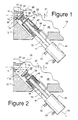
- a slit valve apparatus 10 in accordance with the present invention includes a chamber wall 12 provided with an aperture 14 having a major axis 16 perpendicular to the plane of the paper and having a minor axis 18.
- the aperture 14 is adapted to pass an object, such as an integrated circuit wafer, substantially parallel to a transfer plane 20 which is parallel to the major axis 16 and perpendicular to the minor axis 18.
- the object can also be moved through aperture 14 along any plane parallel to transfer plane 20 or close to parallel to transfer plane 20.
- a seat 22 includes a first seating surface 24 which defines a sealing plane 26 which is angularly disposed with respect to the transfer plane 20.
- a door 28 has a second seating surface 30 which is matingly engageable with the first seating surface 24 along sealing plane 26.
- the door 28 is coupled to a linear actuator mechanism 32.
- An O-ring seal 34 is provided on door 28 to provide effective sealing between the door 28 and the seat 22.
- the linear actuator mechanism 32 includes an elongated shaft 36, an adjustment mechanism 38 coupling a first end of the shaft 36 to door 28 and a reciprocal linear drive mechanism 40 coupled to a second end of shaft 36.
- the mechanism 40 is rigidly coupled to the wall 12 by a bracket 41.
- a shaft guide 42 is coupled to wall 12 and an O-ring 44 is provided to seal the shaft guide 42 to the wall.
- An expansible bellow sleeve 46 is sealed at one end to the adjustment mechanism 38 and at the other end to shaft guide 42. As such, the sliding frictional engagement between shaft 36 and the shaft guide 42 is isolated from the interior 48 of the chamber.
- the linear drive mechanism is preferably a commercially available pneumatic actuator which causes the shaft 36 to move away from the mechanism 40 when air pressure is applied to a first inlet 50 and away from the mechanism 40 when air pressure is applied to a second inlet 52.
- Fig. 2 air pressure has been applied to inlet 52 causing the door 28 to move linearly away from sealing plane 26 along an actuator axis 54 which is substantially perpendicular to the sealing plane 26.
- the shaft guide 42 serves as a stop to limit the motion of the shaft 36 towards the linear drive mechanism 40.
- the door 28 can be biased towards an open position, a closed position, or some intermediate position by an appropriate biasing mechanism (not shown).
- the linear drive mechanism 40 delivers all of its force along actuator axis 54 perpendicularly to the valve seat 22. This not only reduces the amount of force which must be applied by the actuator mechanism 32, but it also minimizes rubbing between the O-ring 34 and the first seating surface 24, thereby reducing particulate generation and O-ring wear.
- the angle A between the transfer plane 20 and the sealing plane 26 is preferably in the range of 30° - 60° and is most preferably approximately 45°. If the angle A becomes much greater than about 60° the stroke of the shaft 36 must become very long to allow the door 28 to clear the bottom plane 56 of the aperture 14. If the angle A becomes much less than 30° the first seating surface 24 will become excessively large promoting possible leakage and requiring larger pressures to be exerted by the linear drive mechanism 40. An angle A of 45° is a good compromise between excessive stroke length of the shaft 36 and moderate closing pressure required of linear drive mechanism 40.
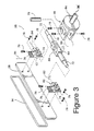
- an exploded isometric view of the adjustment mechanism 38 shows a bracket assembly 58, an axle 60 and a pair of axle bearings 62.
- a circular plate 64 of the bracket assembly is attached to shaft 36 and sealed to bellow sleeve 46 and a pair of fingers 66 engage a central portion 68 of axle 60 by means of a pivot pin 70.
- Bearing surfaces 72 of axle 60 engage bores 74 of the axle bearings 62.
- Ears 76 of the axle bearings 62 are attached to the door 28.
- a number of machine screws 78 create a locking mechanism for locking the position of the door 28 relative to shaft 36 and for holding the adjustment mechanism 38 together.
- the adjustment mechanism 38 permits four separate adjustments to be made to the position of the door 28 relative to valve seat 22.
- a first adjustment 80 adjusts the left-right angular position of the door 28.
- a second adjustment 82 adjusts the up-down angular position of the door.
- a third adjustment 84 adjusts the left-right linear position of the door 28 relative the valve seat 22.
- a fourth adjustment 86 adjusts the up-down linear position of the door 28.
- the screws 78 are loosened and the door 28 is closed by applying air pressure to inlet 50 of the linear drive mechanism 40.
- the angular adjustments 80 and 82 are made automatically by the pressing of the first seating surface 24 against the second seating surface 30 and the linear adjustments 84 and 86 are made manually, if necessary.
- the screws 78 are tightened to lock the door 28 into position. It should be noted that once the adjustment mechanism 38 is locked there are no moving parts to cause friction within the chamber interior 48.
Abstract
Description
- This invention relates generally to slit valve assemblies and methods and more particularly to slit valve assemblies and methods used in semiconductor manufacturing equipment.
- Semiconductor manufacturing equipment often include a number of adjacent but independently sealable chambers. For example, a single piece of semiconductor manufacturing equipment might include a number of processing chambers and one or more load-lock chambers clustered around a central robotic transfer chamber. To pass a semiconductor wafer between chambers elongated apertures or "slits" are provided in the walls between the chambers. These apertures can be selectively opened or closed by means of slit valves.
- There are a great many types of slit valves known in the prior art. For example, in U.S. patent 4,785,962 of Toshima a vacuum chamber slit valve is disclosed which includes a door pivotally mounted near an aperture and pneumatically actuated cam follower rollers which selectively pivot the door between an open and closed position. Another approach is taken by Hutchinson in U.S. patent 4,715,764 who teaches a gate valve having an angularly disposed seat portion and a mating angular closure portion which moves vertically towards the seat portion. A third approach is disclosed in Vacuum Valves 90, May 1, 1989, pp. 24-29, a product catalog of VAT, Inc. VAT, Inc. provides a rectangular valve having a stepped seat which is engaged by a mating gate which moves perpendicularly with respect to the aperture.
- There are several problems with gate valves of the prior art. Firstly, they all include bearing surfaces within the chamber which can generate particulates by surface-to-surface friction Secondly, the force required to hold the gate valves in their closed position tends to be relatively large because the closing force is always at an angle to the seat surface. In consequence, considerable force must be applied to the doors of prior art slit valves to properly seal them against their valve seats.
- It is therefore an object of this invention to provide a gate valve assembly which requires less sealing force than prior art gate valve assemblies and which does not have any particulate producing friction surfaces within the chamber with which it is associated.
- The apparatus of the present invention includes a chamber wall defining an aperture through which integrated circuit wafers may be passed along a transfer plane. The slit valve assembly further includes a seat surrounding the aperture and having a first seating surface defining a seating plane which is angularly disposed with respect to the transfer plane and a door having a second seating surface matingly engageable with the first seating surface. Finally, the slit valve apparatus includes a linear actuator mechanism for linearly moving the door towards and away from the seat along an actuator axis substantially perpendicular to the seating plane. The frictionally engaged portions of the linear actuator mechanism are enclosed within an expansible bellow sleeve to isolate all frictionally engaged surfaces from the interior of the chamber.
- The method of the present invention involves surrounding an elongated aperture with a first sealing surface defining a sealing plane which is angularly disposed with respect to a transfer plane extending through said aperture and engaging or disengaging a second seating surface with the first seating surface by linearly moving the second seating surface in a direction substantially perpendicular to the sealing plane. The orientation of the first seating surface and the second seating surface is adjusted by deactivating a locking mechanism which locks the position of the second seating surface, engaging the first and second seating surfaces, and then reactivating the locking mechanism.
- An advantage of the present invention is that the opening and closing motion of the door is linear and perpendicular to the valve seat. Since the all of the force applied to the door is normal to the seating surfaces less pressure needs to be applied to the door to provide an effective seal.
- Another advantage of the present invention is that all frictional surfaces are isolated from the interior of the chamber by the bellow sleeve. This dramatically reduces particulate formation which can increase the yield of wafers processed within the semiconductor manufacturing equipment.
- These and other advantages of the present invention will become clear to those skilled in the art upon a study of the detailed description of the invention and of the several figures of the drawings.
-
- Figure 1 is a partial cross-sectional elevational view of a slit valve apparatus in accordance with the present invention with the slit valve in a closed position;
- Figure 2 is the same view as Fig. 1 with the slit valve in an open position; and
- Figure 3 is an exploded isometric view of the adjustable support for the valve door of the present invention.
- In Fig. 1, a
slit valve apparatus 10 in accordance with the present invention includes achamber wall 12 provided with anaperture 14 having amajor axis 16 perpendicular to the plane of the paper and having aminor axis 18. Theaperture 14 is adapted to pass an object, such as an integrated circuit wafer, substantially parallel to atransfer plane 20 which is parallel to themajor axis 16 and perpendicular to theminor axis 18. As suggested by thearrow 21, the object can also be moved throughaperture 14 along any plane parallel to transferplane 20 or close to parallel to transferplane 20. Aseat 22 includes afirst seating surface 24 which defines asealing plane 26 which is angularly disposed with respect to thetransfer plane 20. Adoor 28 has asecond seating surface 30 which is matingly engageable with thefirst seating surface 24 alongsealing plane 26. Thedoor 28 is coupled to alinear actuator mechanism 32. An O-ring seal 34 is provided ondoor 28 to provide effective sealing between thedoor 28 and theseat 22. - The
linear actuator mechanism 32 includes anelongated shaft 36, anadjustment mechanism 38 coupling a first end of theshaft 36 todoor 28 and a reciprocallinear drive mechanism 40 coupled to a second end ofshaft 36. Themechanism 40 is rigidly coupled to thewall 12 by abracket 41. Ashaft guide 42 is coupled towall 12 and an O-ring 44 is provided to seal theshaft guide 42 to the wall. Anexpansible bellow sleeve 46 is sealed at one end to theadjustment mechanism 38 and at the other end toshaft guide 42. As such, the sliding frictional engagement betweenshaft 36 and theshaft guide 42 is isolated from theinterior 48 of the chamber. The linear drive mechanism is preferably a commercially available pneumatic actuator which causes theshaft 36 to move away from themechanism 40 when air pressure is applied to afirst inlet 50 and away from themechanism 40 when air pressure is applied to asecond inlet 52. - In Fig. 2, air pressure has been applied to
inlet 52 causing thedoor 28 to move linearly away fromsealing plane 26 along anactuator axis 54 which is substantially perpendicular to thesealing plane 26. Theshaft guide 42 serves as a stop to limit the motion of theshaft 36 towards thelinear drive mechanism 40. Thedoor 28 can be biased towards an open position, a closed position, or some intermediate position by an appropriate biasing mechanism (not shown). - It should be noted that all friction creating surfaces are isolated from the
interior 48 of the chamber by thebellow sleeve 46. It is therefore very unlikely that theslit valve apparatus 10 will produce any particulates within thechamber interior 48, thereby eliminating a potential source of contamination. It should also be noted that thelinear drive mechanism 40 delivers all of its force alongactuator axis 54 perpendicularly to thevalve seat 22. This not only reduces the amount of force which must be applied by theactuator mechanism 32, but it also minimizes rubbing between the O-ring 34 and thefirst seating surface 24, thereby reducing particulate generation and O-ring wear. - The angle A between the
transfer plane 20 and thesealing plane 26 is preferably in the range of 30° - 60° and is most preferably approximately 45°. If the angle A becomes much greater than about 60° the stroke of theshaft 36 must become very long to allow thedoor 28 to clear thebottom plane 56 of theaperture 14. If the angle A becomes much less than 30° thefirst seating surface 24 will become excessively large promoting possible leakage and requiring larger pressures to be exerted by thelinear drive mechanism 40. An angle A of 45° is a good compromise between excessive stroke length of theshaft 36 and moderate closing pressure required oflinear drive mechanism 40. - In Fig. 3, an exploded isometric view of the
adjustment mechanism 38 shows abracket assembly 58, anaxle 60 and a pair ofaxle bearings 62. Acircular plate 64 of the bracket assembly is attached toshaft 36 and sealed tobellow sleeve 46 and a pair of fingers 66 engage acentral portion 68 ofaxle 60 by means of apivot pin 70.Bearing surfaces 72 ofaxle 60 engagebores 74 of theaxle bearings 62.Ears 76 of theaxle bearings 62 are attached to thedoor 28. A number ofmachine screws 78 create a locking mechanism for locking the position of thedoor 28 relative toshaft 36 and for holding theadjustment mechanism 38 together. - The
adjustment mechanism 38 permits four separate adjustments to be made to the position of thedoor 28 relative tovalve seat 22. Afirst adjustment 80 adjusts the left-right angular position of thedoor 28. Asecond adjustment 82 adjusts the up-down angular position of the door. Athird adjustment 84 adjusts the left-right linear position of thedoor 28 relative thevalve seat 22. Finally, afourth adjustment 86 adjusts the up-down linear position of thedoor 28. - To properly adjust the
door 28 to thevalve seat 22, thescrews 78 are loosened and thedoor 28 is closed by applying air pressure toinlet 50 of thelinear drive mechanism 40. Theangular adjustments first seating surface 24 against thesecond seating surface 30 and thelinear adjustments door 28 is properly positioned, thescrews 78 are tightened to lock thedoor 28 into position. It should be noted that once theadjustment mechanism 38 is locked there are no moving parts to cause friction within thechamber interior 48. - While this invention has been described in terms of several preferred embodiments, it is contemplated that various alterations and permutations thereof will become apparent to those skilled in the art. It is therefore intended that the appended claims include all such alterations and permutations as fall within the true spirit and scope of the present invention.
Claims (10)
- A slit valve apparatus (10) comprising:- wall means (12) defining an aperture (14) having a major axis (16) and a minor axis (18), said aperture (14) being adapted to pass an object along a transfer plane (20) substantially parallel to said major axis (16) and perpendicular to said minor axis (18);- seat means (22) surrounding said aperture (14), said seat means (22) having a first seating surface (24) defining a sealing plane (26) which is angularly disposed with respect to said transfer plane (20);- door means (28) having a second seating surface (30) which is matingly engageable with said first seating surface (24) along said sealing plane (26); and- linear actuator means (32) for selectively moving said door means (28) towards and away from said seat means (22) along an actuator axis (54) which is substantially perpendicular to said sealing plane (26).
- The apparatus (10) of claim 1, wherein the included angle between said transfer plane (20) and said sealing plane (26) is in the range of 30° - 60°, preferably about 45°.
- The apparatus of claim 1 or 2, wherein said linear actuator means (32) includes an elongated shaft (36) coupled at a first end to said door means (28) and coupled at a second end to a reciprocal linear drive mechanism (40), preferably a pneumatically actuated mechanism.
- The apparatus of claim 3, wherein said shaft (36) passes through said wall means and further comprising guide means (42) coupled to said wall means (12) for guiding said shaft (36) along said actuator axis (54) and enclosure means (46) coupling said first end of said shaft (36) to said wall means (12).
- The apparatus of any preceding claim, further comprising multi-axis adjustment means (38) coupling said first end of said shaft (36) to said door means (28).
- The apparatus of claim 4 or 5, wherein said enclosure means comprises a bellows (46) coupled at a first end to said shaft (36) and coupled at a second end to said wall means (26).
- The apparatus of any preceding claim, further comprising first sealing means (34) disposed between said first seating surface and said second seating surface and/or second sealing means (44) disposed between said bellow (46) and said wall means (28).
- A method for selectively opening or closing an elongated aperture (14) provided in a wall (12) through which objects may be passed substantially parallel to a transfer plane (20) comprising the steps of:- surrounding said aperture (14) with a first seating surface (24) defining a sealing plane (28) which is angularly disposed with respect to said transfer plane (20); and- engaging or disengaging a second seating surface (30) with said first seating surface (24) by linearly moving said second seating surface (30) in a direction substantially perpendicular to said sealing plane (28).
- The method of claim 8, further comprising the step of adjusting the orientation of said first seating surface (24) and said second seating surface (30) such that they are substantially parallel and such that said aperture (14) is completely covered by said second seating surface (30) when said second seating surface (30) is engaged with said first seating surface (24).
- The method of claim 9, wherein said step of adjusting said orientation is accomplished by:- deactivating locking means (78) which locks the position of said second seating surface (30);- engaging said first seating surface (24) and said second seating surface (30); and- reactivating said locking means (78).
Applications Claiming Priority (2)
| Application Number | Priority Date | Filing Date | Title |
|---|---|---|---|
| US51165890A | 1990-04-20 | 1990-04-20 | |
| US511658 | 1990-04-20 |
Publications (2)
| Publication Number | Publication Date |
|---|---|
| EP0453867A1 true EP0453867A1 (en) | 1991-10-30 |
| EP0453867B1 EP0453867B1 (en) | 1994-08-10 |
Family
ID=24035863
Family Applications (1)
| Application Number | Title | Priority Date | Filing Date |
|---|---|---|---|
| EP91105626A Expired - Lifetime EP0453867B1 (en) | 1990-04-20 | 1991-04-09 | Slit valve apparatus and method |
Country Status (5)
| Country | Link |
|---|---|
| EP (1) | EP0453867B1 (en) |
| JP (1) | JP2682904B2 (en) |
| KR (1) | KR100210693B1 (en) |
| DE (1) | DE69103316T2 (en) |
| ES (1) | ES2062595T3 (en) |
Cited By (10)
| Publication number | Priority date | Publication date | Assignee | Title |
|---|---|---|---|---|
| EP0735574A1 (en) * | 1995-03-31 | 1996-10-02 | Applied Materials, Inc. | Improved slit valve door |
| WO1998001887A1 (en) * | 1996-07-09 | 1998-01-15 | Lam Research Corporation | Chamber interfacing o-rings and method for implementing same |
| WO1999003136A1 (en) * | 1997-07-11 | 1999-01-21 | Applied Materials, Inc. | Two-piece slit valve insert for vacuum processing system |
| WO2001055628A1 (en) * | 2000-01-26 | 2001-08-02 | Tokyo Electron Limited | High pressure lift valve for use in semiconductor processing environment |
| US6736149B2 (en) | 1999-11-02 | 2004-05-18 | Supercritical Systems, Inc. | Method and apparatus for supercritical processing of multiple workpieces |
| WO2004094884A1 (en) * | 2003-04-17 | 2004-11-04 | Applied Materials, Inc. | Slit valve method and apparatus |
| EP1622195A1 (en) * | 2004-07-21 | 2006-02-01 | Afore Oy | Apparatus and method for testing devices fabricated in a wafer |
| US7767145B2 (en) | 2005-03-28 | 2010-08-03 | Toyko Electron Limited | High pressure fourier transform infrared cell |
| US7789971B2 (en) | 2005-05-13 | 2010-09-07 | Tokyo Electron Limited | Treatment of substrate using functionalizing agent in supercritical carbon dioxide |
| CN113137488A (en) * | 2020-01-17 | 2021-07-20 | 夏泰鑫半导体(青岛)有限公司 | Slit valve and wafer processing system |
Families Citing this family (5)
| Publication number | Priority date | Publication date | Assignee | Title |
|---|---|---|---|---|
| KR200460437Y1 (en) * | 2011-10-04 | 2012-05-25 | 주식회사 토르 | Slit valve for semiconductor fabrication equipment |
| KR102523112B1 (en) * | 2016-08-22 | 2023-04-18 | 삼성전자주식회사 | Silt valve apparatus and substrate treating facility using the same |
| JP6938761B2 (en) | 2017-07-31 | 2021-09-22 | アプライド マテリアルズ インコーポレイテッドApplied Materials,Incorporated | Gas supply member with baffle |
| KR102433880B1 (en) | 2020-04-14 | 2022-08-18 | 프리시스 주식회사 | Gate valve |
| DE102021102284A1 (en) | 2021-02-01 | 2022-08-04 | Vat Holding Ag | Valve plate for a closure device for vacuum-tight closure of an opening in a wall |
Citations (4)
| Publication number | Priority date | Publication date | Assignee | Title |
|---|---|---|---|---|
| US4166607A (en) * | 1976-10-14 | 1979-09-04 | Hoke, Inc. | Bellows seal valve |
| EP0242997A2 (en) * | 1986-04-17 | 1987-10-28 | Varian Associates, Inc. | Valve incorporating wafer handling arm |
| US4715764A (en) | 1986-04-28 | 1987-12-29 | Varian Associates, Inc. | Gate valve for wafer processing system |
| US4785962A (en) | 1987-04-20 | 1988-11-22 | Applied Materials, Inc. | Vacuum chamber slit valve |
Family Cites Families (1)
| Publication number | Priority date | Publication date | Assignee | Title |
|---|---|---|---|---|
| JPS519736U (en) * | 1974-07-08 | 1976-01-24 |
-
1991
- 1991-04-09 DE DE69103316T patent/DE69103316T2/en not_active Expired - Fee Related
- 1991-04-09 ES ES91105626T patent/ES2062595T3/en not_active Expired - Lifetime
- 1991-04-09 EP EP91105626A patent/EP0453867B1/en not_active Expired - Lifetime
- 1991-04-18 JP JP3086498A patent/JP2682904B2/en not_active Expired - Fee Related
- 1991-04-19 KR KR1019910006263A patent/KR100210693B1/en not_active IP Right Cessation
Patent Citations (4)
| Publication number | Priority date | Publication date | Assignee | Title |
|---|---|---|---|---|
| US4166607A (en) * | 1976-10-14 | 1979-09-04 | Hoke, Inc. | Bellows seal valve |
| EP0242997A2 (en) * | 1986-04-17 | 1987-10-28 | Varian Associates, Inc. | Valve incorporating wafer handling arm |
| US4715764A (en) | 1986-04-28 | 1987-12-29 | Varian Associates, Inc. | Gate valve for wafer processing system |
| US4785962A (en) | 1987-04-20 | 1988-11-22 | Applied Materials, Inc. | Vacuum chamber slit valve |
Non-Patent Citations (1)
| Title |
|---|
| VACUUM VALVES 90, 1 May 1989 (1989-05-01), pages 24 - 29 |
Cited By (14)
| Publication number | Priority date | Publication date | Assignee | Title |
|---|---|---|---|---|
| EP0735574A1 (en) * | 1995-03-31 | 1996-10-02 | Applied Materials, Inc. | Improved slit valve door |
| WO1998001887A1 (en) * | 1996-07-09 | 1998-01-15 | Lam Research Corporation | Chamber interfacing o-rings and method for implementing same |
| US6010133A (en) * | 1996-07-09 | 2000-01-04 | Lam Research Corporation | Chamber interfacing O-rings and method for implementing same |
| WO1999003136A1 (en) * | 1997-07-11 | 1999-01-21 | Applied Materials, Inc. | Two-piece slit valve insert for vacuum processing system |
| US6045620A (en) * | 1997-07-11 | 2000-04-04 | Applied Materials, Inc. | Two-piece slit valve insert for vacuum processing system |
| US6736149B2 (en) | 1999-11-02 | 2004-05-18 | Supercritical Systems, Inc. | Method and apparatus for supercritical processing of multiple workpieces |
| US6748960B1 (en) | 1999-11-02 | 2004-06-15 | Tokyo Electron Limited | Apparatus for supercritical processing of multiple workpieces |
| WO2001055628A1 (en) * | 2000-01-26 | 2001-08-02 | Tokyo Electron Limited | High pressure lift valve for use in semiconductor processing environment |
| WO2004094884A1 (en) * | 2003-04-17 | 2004-11-04 | Applied Materials, Inc. | Slit valve method and apparatus |
| US7007919B2 (en) | 2003-04-17 | 2006-03-07 | Applied Materials, Inc. | Slit valve method and apparatus |
| EP1622195A1 (en) * | 2004-07-21 | 2006-02-01 | Afore Oy | Apparatus and method for testing devices fabricated in a wafer |
| US7767145B2 (en) | 2005-03-28 | 2010-08-03 | Toyko Electron Limited | High pressure fourier transform infrared cell |
| US7789971B2 (en) | 2005-05-13 | 2010-09-07 | Tokyo Electron Limited | Treatment of substrate using functionalizing agent in supercritical carbon dioxide |
| CN113137488A (en) * | 2020-01-17 | 2021-07-20 | 夏泰鑫半导体(青岛)有限公司 | Slit valve and wafer processing system |
Also Published As
| Publication number | Publication date |
|---|---|
| EP0453867B1 (en) | 1994-08-10 |
| DE69103316D1 (en) | 1994-09-15 |
| KR100210693B1 (en) | 1999-07-15 |
| JPH04228978A (en) | 1992-08-18 |
| KR910018705A (en) | 1991-11-30 |
| JP2682904B2 (en) | 1997-11-26 |
| DE69103316T2 (en) | 1995-04-27 |
| ES2062595T3 (en) | 1994-12-16 |
Similar Documents
| Publication | Publication Date | Title |
|---|---|---|
| US5226632A (en) | Slit valve apparatus and method | |
| EP0453867B1 (en) | Slit valve apparatus and method | |
| US4785962A (en) | Vacuum chamber slit valve | |
| JP2766190B2 (en) | No sliding vacuum gate valve | |
| US7032882B2 (en) | Valve assembly having novel flow characteristics | |
| US5275303A (en) | Valve closure mechanism for semiconductor deposition apparatus | |
| US7036794B2 (en) | Method for control of a vacuum valve arranged between two vacuum chambers | |
| EP1105605B1 (en) | Pod door to port door retention system | |
| US7371285B2 (en) | Motorized chamber lid | |
| JP5038895B2 (en) | Gate device | |
| US20080017823A1 (en) | Vacuum valve and closure disc which can be mounted on a connecting rod | |
| JP2019083307A (en) | Vacuum adjustment device | |
| US6227236B1 (en) | Widely variable conductance valve | |
| WO2002001035A3 (en) | Dual pendulum valve assembly | |
| US6032419A (en) | Vacuum processing apparatus with low particle generating vacuum seal | |
| US20050274416A1 (en) | Collets for use with process control devices | |
| JP2682904C (en) | ||
| WO2020109349A1 (en) | Lock device, lock system, and method for operating a lock device | |
| KR20210120112A (en) | Gate valve with sliding guide | |
| JPH0143190B2 (en) | ||
| JP2002303372A (en) | Gate valve and apparatus and method for vacuum processing | |
| JPH10339376A (en) | Gate valve | |
| JP2003090668A (en) | Passage opening/closing unit | |
| JPH0413424B2 (en) | ||
| JPH0590268U (en) | Electric expansion valve |
Legal Events
| Date | Code | Title | Description |
|---|---|---|---|
| PUAI | Public reference made under article 153(3) epc to a published international application that has entered the european phase |
Free format text: ORIGINAL CODE: 0009012 |
|
| AK | Designated contracting states |
Kind code of ref document: A1 Designated state(s): BE CH DE ES FR GB IT LI NL |
|
| 17P | Request for examination filed |
Effective date: 19920430 |
|
| 17Q | First examination report despatched |
Effective date: 19931014 |
|
| GRAA | (expected) grant |
Free format text: ORIGINAL CODE: 0009210 |
|
| AK | Designated contracting states |
Kind code of ref document: B1 Designated state(s): BE CH DE ES FR GB IT LI NL |
|
| REF | Corresponds to: |
Ref document number: 69103316 Country of ref document: DE Date of ref document: 19940915 |
|
| ITF | It: translation for a ep patent filed |
Owner name: ING. C. GREGORJ S.P.A. |
|
| ET | Fr: translation filed | ||
| REG | Reference to a national code |
Ref country code: ES Ref legal event code: FG2A Ref document number: 2062595 Country of ref document: ES Kind code of ref document: T3 |
|
| PLBE | No opposition filed within time limit |
Free format text: ORIGINAL CODE: 0009261 |
|
| STAA | Information on the status of an ep patent application or granted ep patent |
Free format text: STATUS: NO OPPOSITION FILED WITHIN TIME LIMIT |
|
| 26N | No opposition filed | ||
| PGFP | Annual fee paid to national office [announced via postgrant information from national office to epo] |
Ref country code: FR Payment date: 19990226 Year of fee payment: 9 |
|
| PGFP | Annual fee paid to national office [announced via postgrant information from national office to epo] |
Ref country code: ES Payment date: 19990428 Year of fee payment: 9 |
|
| PG25 | Lapsed in a contracting state [announced via postgrant information from national office to epo] |
Ref country code: ES Free format text: THE PATENT HAS BEEN ANNULLED BY A DECISION OF A NATIONAL AUTHORITY Effective date: 20000410 |
|
| PG25 | Lapsed in a contracting state [announced via postgrant information from national office to epo] |
Ref country code: FR Free format text: LAPSE BECAUSE OF NON-PAYMENT OF DUE FEES Effective date: 20001229 |
|
| REG | Reference to a national code |
Ref country code: FR Ref legal event code: ST |
|
| REG | Reference to a national code |
Ref country code: GB Ref legal event code: IF02 |
|
| REG | Reference to a national code |
Ref country code: ES Ref legal event code: FD2A Effective date: 20020204 |
|
| PGFP | Annual fee paid to national office [announced via postgrant information from national office to epo] |
Ref country code: GB Payment date: 20020402 Year of fee payment: 12 |
|
| PGFP | Annual fee paid to national office [announced via postgrant information from national office to epo] |
Ref country code: CH Payment date: 20020425 Year of fee payment: 12 |
|
| PGFP | Annual fee paid to national office [announced via postgrant information from national office to epo] |
Ref country code: DE Payment date: 20020426 Year of fee payment: 12 |
|
| PGFP | Annual fee paid to national office [announced via postgrant information from national office to epo] |
Ref country code: NL Payment date: 20020430 Year of fee payment: 12 |
|
| PGFP | Annual fee paid to national office [announced via postgrant information from national office to epo] |
Ref country code: BE Payment date: 20020524 Year of fee payment: 12 |
|
| PG25 | Lapsed in a contracting state [announced via postgrant information from national office to epo] |
Ref country code: GB Free format text: LAPSE BECAUSE OF NON-PAYMENT OF DUE FEES Effective date: 20030409 |
|
| PG25 | Lapsed in a contracting state [announced via postgrant information from national office to epo] |
Ref country code: LI Free format text: LAPSE BECAUSE OF NON-PAYMENT OF DUE FEES Effective date: 20030430 Ref country code: CH Free format text: LAPSE BECAUSE OF NON-PAYMENT OF DUE FEES Effective date: 20030430 Ref country code: BE Free format text: LAPSE BECAUSE OF NON-PAYMENT OF DUE FEES Effective date: 20030430 |
|
| BERE | Be: lapsed |
Owner name: *APPLIED MATERIALS INC. Effective date: 20030430 |
|
| PG25 | Lapsed in a contracting state [announced via postgrant information from national office to epo] |
Ref country code: NL Free format text: LAPSE BECAUSE OF NON-PAYMENT OF DUE FEES Effective date: 20031101 Ref country code: DE Free format text: LAPSE BECAUSE OF NON-PAYMENT OF DUE FEES Effective date: 20031101 |
|
| GBPC | Gb: european patent ceased through non-payment of renewal fee |
Effective date: 20030409 |
|
| NLV4 | Nl: lapsed or anulled due to non-payment of the annual fee |
Effective date: 20031101 |
|
| REG | Reference to a national code |
Ref country code: CH Ref legal event code: PL |
|
| PG25 | Lapsed in a contracting state [announced via postgrant information from national office to epo] |
Ref country code: IT Free format text: LAPSE BECAUSE OF NON-PAYMENT OF DUE FEES;WARNING: LAPSES OF ITALIAN PATENTS WITH EFFECTIVE DATE BEFORE 2007 MAY HAVE OCCURRED AT ANY TIME BEFORE 2007. THE CORRECT EFFECTIVE DATE MAY BE DIFFERENT FROM THE ONE RECORDED. Effective date: 20050409 |