EP0451371A1 - A method and system for organizing and accessing product describing data pertaining to an engineering process - Google Patents
A method and system for organizing and accessing product describing data pertaining to an engineering process Download PDFInfo
- Publication number
- EP0451371A1 EP0451371A1 EP90200919A EP90200919A EP0451371A1 EP 0451371 A1 EP0451371 A1 EP 0451371A1 EP 90200919 A EP90200919 A EP 90200919A EP 90200919 A EP90200919 A EP 90200919A EP 0451371 A1 EP0451371 A1 EP 0451371A1
- Authority
- EP
- European Patent Office
- Prior art keywords
- data
- nodes
- flow
- node
- engineering
- Prior art date
- Legal status (The legal status is an assumption and is not a legal conclusion. Google has not performed a legal analysis and makes no representation as to the accuracy of the status listed.)
- Granted
Links
Images


Classifications
-
- G—PHYSICS
- G06—COMPUTING; CALCULATING OR COUNTING
- G06F—ELECTRIC DIGITAL DATA PROCESSING
- G06F16/00—Information retrieval; Database structures therefor; File system structures therefor
- G06F16/90—Details of database functions independent of the retrieved data types
- G06F16/901—Indexing; Data structures therefor; Storage structures
- G06F16/9024—Graphs; Linked lists
-
- G—PHYSICS
- G06—COMPUTING; CALCULATING OR COUNTING
- G06F—ELECTRIC DIGITAL DATA PROCESSING
- G06F30/00—Computer-aided design [CAD]
-
- G—PHYSICS
- G06—COMPUTING; CALCULATING OR COUNTING
- G06F—ELECTRIC DIGITAL DATA PROCESSING
- G06F40/00—Handling natural language data
- G06F40/10—Text processing
- G06F40/12—Use of codes for handling textual entities
- G06F40/14—Tree-structured documents
-
- G—PHYSICS
- G06—COMPUTING; CALCULATING OR COUNTING
- G06F—ELECTRIC DIGITAL DATA PROCESSING
- G06F40/00—Handling natural language data
- G06F40/10—Text processing
- G06F40/12—Use of codes for handling textual entities
- G06F40/151—Transformation
-
- G—PHYSICS
- G06—COMPUTING; CALCULATING OR COUNTING
- G06F—ELECTRIC DIGITAL DATA PROCESSING
- G06F40/00—Handling natural language data
- G06F40/10—Text processing
- G06F40/197—Version control
-
- Y—GENERAL TAGGING OF NEW TECHNOLOGICAL DEVELOPMENTS; GENERAL TAGGING OF CROSS-SECTIONAL TECHNOLOGIES SPANNING OVER SEVERAL SECTIONS OF THE IPC; TECHNICAL SUBJECTS COVERED BY FORMER USPC CROSS-REFERENCE ART COLLECTIONS [XRACs] AND DIGESTS
- Y10—TECHNICAL SUBJECTS COVERED BY FORMER USPC
- Y10S—TECHNICAL SUBJECTS COVERED BY FORMER USPC CROSS-REFERENCE ART COLLECTIONS [XRACs] AND DIGESTS
- Y10S707/00—Data processing: database and file management or data structures
- Y10S707/99931—Database or file accessing
Definitions
- any subprocess or lower level subprocess may again produce product describing data which is mapped on a particular data node in the second directed-acyclic-graph.
- the level of subprocesses is aggregated or kept disjunct, as the situation requires.
- the product describing data may be electronic engineering data as explained earlier.
- the product may be a mechanical engineering product, a software engineering product, or the engineering product may itself be an engineering process.
- Figure 1 may be changed in that the various data representations of running a particular tool be each assigned a given box, e.g. in that box 36 had been divided into box 36A, leading exclusively to tool box 28, and another box 36B leading exclusively to tool box 30 (assuming that each of the latter tools need only a single data representation, which would be unique and mutually exclusive between tool boxes 28, 30). It should be noted that Figure 1 should show all items and links with respect to the tools shown. Thus, tool 20 only outputs to block 32. Tool 24 exclusively feeds on data from that in block 32 and exclusively outputs to block 36.
- Figure 1 mathematically is a tree. Alternatively, the graph could have two source nodes linking to a single destination node.
- these structures will be supplemented with additional structures dealing with the various functional extensions without departing from the present inventive concept.
- additional structures may be, for example, (parts of) hierarchies used in describing the design data or information, characterizing the allowed or selected invocation options for individual flow nodes.
- Form the logical data organization shown, the physical organization, such as logical/physical addressing, labeling, referencing between records, displaying, inputting, outputting and various other physical-directed operations may be effected in completely conventional way.
- the structures shown are only minute examples of databases that may exhibit extreme degrees of complexity and massive storage requirements without departing from the present inventive concept.
- Block 72 represents engineering subprocesses which each require a set of input representations in order to produce a set of output representations. Representations are fed into a subprocess via input slots (74). Representations generated by the execution of a subprocess become available at output slots (80). Relationship types 84 and 88 respectively link each input and output slot to the corresponding engineering subprocess (72). Relationship type 86 indicates which input slots (74) are connected to which output slot (80). Together, elements 72, 74, 80, 84, 86 and 88 form a data flow model indicating how the various engineering subprocesses make use of the representations generated by other engineering subprocesses.
Abstract
Description
- The invention relates to a method for organizing and accessing product describing data pertaining to an engineering process, in particular, but not exclusively for use in an electronic engineering environment, such as computer aided design of an integrated circuit and its associated data files. In the above, pertaining means generated by the process and used outside the process, or generated outside the process and used by the process, or both generated and used by the process. Similar considerations apply on the subprocess level. Such an electronic or other engineering process requires a sequence of operation steps, of which a typical example could be a silicon compiler system such as described in United States Patent Application 156,392, filed February 16, 1988, herein incorporated by reference, now patent , and corresponding to EP application 89200310.4, (PHQ 88.005) assigned to the same assignee. Successive steps in silicon compilation may be:
- A. receiving a source text expressing an algorithm in an imperative concurrent computer language;
- B. converting this text to a structure tree as an abstract representation of the source text;
- C. converting the structure tree to an abstract circuit representation featuring abstract channels;
- D. converting the abstract circuit to a concrete circuit representation being constituted of gate level elements and wires;
- E. next, generating a so-called net-list, which specifies all electronic elements and their interconnections;
- F. from the net-list, generating a lay-out;
- G. from the lay-out so generated, executing a simulated test operation.
- With increasing levels of complexity and sophistication, the amounts of data, the number of data files, the complexity of their relations and, in consequence, problems relating with managing such data, grow exponentially, caused inter alia by the design being characterizeable as a trial and error process. Systems for organizing and managing the body of information with the intent of supporting the engineers involved may be called frameworks. Access must be easy and secure. This may be effected by placing the various data files or units under control of the system which itself possesses control information or design management data relating to the structure and usage of the data files or units. In a refined version, the system could use this control information to organize the data, to provide access to the data and to check requested operations on the data against integrity/security rules. The system also could provide support for certain project management aspects of the engineering process by providing an overview of the available data and their status. At present no adequate solution to the problems sketched has been available.
Important aspects to be dealt with may include: - what units of data belong together?
- what do the data represent?
- which version of the data is this?
- how was this data created?
- where is this data used?
- Among other things, it is an object of the invention to provide a method for organizing and accessing product describing data pertaining to an engineering process, by devising a flexible and powerful set of concepts with which to describe the structure of various sets of engineering data upon their generation and use. Now, concepts used to model the structure of the engineering data include "versioning", "equivalence" and "alternatives", which in our method and system are basically handled using the derivation graph, to be discussed hereinafter. Versioning is a well-known concept in hardware and software for discerning between successive solutions. Equivalence puts various solutions on an equal footing. Alternatives are solutions basing on a particular choice made. Now, the present invention is most suitable/useful under the following conditions:
- 1) the data being managed is subject to numerous changes and/or updates such as is typical in trial and error engineering. The technique may be more suitable for work-in-progress data than for libraries, standards, archives or other bodies of consolidated data.
- 2) the engineering process consists of a significant number of different steps which can each be redone independently of following steps:
although previous steps must have rendered their results available, the process need not run to the end. A prime example of this is electrical engineering (VLSI, ASIC, discrete components). - According to one of its aspects, the invention provides a method for organizing and accessing product describing data, generated and/or used by an engineering process comprising multiple engineering subprocesses, said method comprising:
- a. providing a first set of flow nodes, each individual flow node representing one uniqueof said subprocesses;
- b. performing at least one flow node execution, which flow node execution represents a corresponding subprocess execution which thereby uses and/or generates respective part(s) of said product describing data;
- c. providing a data flow model of the engineering process by linking said flow nodes to form a first directed-acyclic-graph of which each flow link, by connecting one source flow node to one destination flow node, represents as fact that each execution of said destination flow node requires partial or complete usage of product describing data generated by exectuion of said source flow node;
- d. providing a second set of data nodes, each individual data node referencing one unique flow node for so representing one unique individual execution of the flow node so referenced and consequently also representing the product describing data generated by the latter unique individual execution;
- e. providing a model of the product describing data used and/or generated by the engineering process by linking said data nodes to form a second directed-acyclic-graph of which each data link by connecting one source data node to one destination data node, represents as fact partial or complete usage of the product describing data represented by said source data node for generating the product describing data represented by said destination data node;
- f. providing a mechanism for selecting from the second set of data nodes a first subset of data nodes by selecting one first particular flow node which restricts said first subset of data nodes to those data nodes which reference said first particular flow node;
- g. selecting an arbitrary number of auxiliary subsets of data nodes, each auxiliary subset referencing one respective further particular flow node, that is directly or indirectly linked as source flow node to said first particular flow nodes by respective associated flow link or links in said first directed acyclic graph, for so providing a mechanism for reducing said first subset of data nodes to form a final set of data nodes in that from said first subset of data nodes said final subset of data nodes comprises only those data nodes for which the engineering subprocess execution represented thereby directly or indirectly had used the product describing data represented by one of the data nodes in each respective individual auxiliary;
- h. accessing the product describing data represented by said final subset of data nodes using mapping information relating individual data nodes to product describing data residing within a data storage system. So, the method boils down to mapping the subprocesses one-to-one on the flow nodes, linking the flow nodes according to a data-to-data paternity pattern in a first graph, tethering to each flow node the data generated by its execution, linking also the data nodes according to a data-to-data paternity pattern, and accessing the data structure along lines of paternity linkage and/or tethering. In particular, the direction of accessing is now following the links in a downstream direction. This would answer questions like: where is this data used? or which is the consequence of this particular phenomenon encountered? Generally, this procedure would uncover data that were generated by a particular execution.
- Advantageously, a second selection mechanism is provided which involves travelling uniformly along links of said first directed-acyclic-graph in a direction from the destination nodes to the source nodes of the latter links. In particular, the direction of traversal is now following the links in an upstream direction. This would answer questions like: how is this data created? or what is the cause of this particular phenomenon encountered? Generally, this procedure would uncover data that were used by a particular execution. Both upstream travelling and downstream travelling represent attractive accessing strategies.
- Advantageously, each particular data link is coupled to exactly one flow link in that the product describing data represented by either end node of said data link originate from an execution of the processes corresponding to the respective end nodes of the thereto coupled flow link.
Such secondary mapping forces to relevant linking in the data graph. It can also represent a means for additionally checking upon each modification in the database. In particular cases, however, other realizations are feasible. - Advantageously, the first directed-acyclic-graph is extended to an extended directed-acyclic-graph with information about the way in which the product describing data, produced and used, respectively, by executions of the engineering subprocesses is physically partitioned into units and wherein the second directed-acyclic-graph is extended with information mapping said individual units of data residing within a storage system onto elements of the second directed-acyclic-graph.
In this way, the system is able to control the flow of information between programs at the level of individual units. Note that in most cases this additional level of detail can be kept transparent for the end-user. By itself, the grouping of data files to data sets, and, conversely, the distribution of data sets over data files is a conventional database management concept, which in this case would facilitate the accessing. - Advantageously, the flow nodes within the extended directed-acyclic-graph are provided with additional typing information representing the type of engineering subprocess of which they are an instance thereby allowing the usage of the flow nodes in the extended directed-acyclic-graph to be checked against said typing information. Such provision in the lowest level of the three levels (the engineering subprocess typing level) allows for additional integrity checking of the data structure.
- Advantageously, a further subset of the flow nodes of the first directed-acyclic-graph is provided with information pertaining to a physical location and method of invocation of executable programs corresponding to the respective elements of said further subset, thereby allowing the information in the first directed-acyclic-graph to be used to automate and/or support the execution of said executable programs. In this way, the program-related information occurring in the flow nodes can be used to partially or fully automate the invocation of the programs in question. This can, for example, be used to implement additional functionality which is roughly comparable to that of the MAKE facility as commonly used in UNIX software development environments. The latter have become in extensive use.
- Advantageously, an additional type of link is introduced interconnecting flow nodes in the first directed-acyclic-graph thereby representing non-mandatory use of product describing data by executions of the engineering subprocess corresponding to the destination node of said type of links.
This feature is particular useful in editing tools. Alternatively certain types of iteration may benefit. In particular, an optional loop may be created in this way. In the particular case of an editor, the output data thereof may be used as new input data, after original execution of the editor without provision of input data in first instance. - Advantageously, the first directed-acyclic-graph forms a hierarchical model of the engineering process by linking nodes therein representing either individual engineering subprocesses or subgraphs of interlinked engineering subprocesses. Such useful feature of the present invention allows engineering subprocesses to be described in terms of lower level engineering subprocesses. Such a description may be called a nested flow description. Flow nesting can be used to hide lower level subprocesses from the user. For example, the sequence of lower level subprocesses consisting of a pre-processor step, a tool execution and a post-processor step can be represented as a single higher level subprocess in which the pre- and post-processing steps are hidden.
- Another direct application of flow nesting involves assigning users, or groups of users, to one or more subprocesses in the hierarchy of subprocesses. This information can be used to restrict the accessibility and visibility of product describing data generated by the execution of any particular lower level engineering subprocesses to those users who have been assigned to the engineering subprocess containing said particular lower level engineering subprocess.
- The latter application of flow nesting is a new approach to providing functionality which is similar to that of the so-called workspace concept while avoiding some of the implementation and usage complexity associated with the workspace concept.
- As in the foregoing, executing any subprocess or lower level subprocess may again produce product describing data which is mapped on a particular data node in the second directed-acyclic-graph. Depending on the level of microscopism required, the level of subprocesses is aggregated or kept disjunct, as the situation requires.
- Advantageously, such hierarchical description of the engineering process limits the accessibility and visibility of product describing data generated by the execution of flow nodes belonging to a particular level of the hierarchy to those users of the system with appropriate privileges for said particular level.
Such accessibility, visibility, etcetera may represent status of the data, provide protected data access and in other aspects support or provide project management. Thus, the overall engineering process may be accessible to a general category of users, a next lower level may be accessible to users involved specifically in the associated subprocess(es), and so on. The latter users may be maintenance officers, whereas the former only operate to design circuitry using the direct results. Many other distinction levels are feasible. - The invention, moreover, relates to a data management system comprising a physical implementation of a method as described, comprising storage means for storing product describing data represented data by said nodes, graphs, instances and links, input means for inputting further product describing data and user requests and output means for under control of a user request selectively outputting and/or displaying subsets of product describing data stored in said storage means.
Such system is readily implementable on a medium scale computer, such as a Digital Equipment Corporation VAX-computer or the like. Alternative vehicles may be Apollo-type workstations now being manufactured by a subsidiary of Hewlett-Packard Corporation and linked in a computer network. - In particular, advantageously the product describing data may be electronic engineering data as explained earlier. Alternatively, the product may be a mechanical engineering product, a software engineering product, or the engineering product may itself be an engineering process.
- Advantageously, in a method as described supra, one or more feedback links are added to said first directed-acyclic-graph, thereby transforming said first directed-acyclic-graph into a generalized directed graph exhibiting cycles, whereby each feedback link, having exactly one source flow node and exactly one destination flow node, represents the fact that the product describing data generated by an execution of said flow node can optionally be used as input for the execution of said destination flow node, thereby providing the capability of modifying the latter product describing data an arbitrary number of times. This allows for a powerful iteration feature.
- The invention will be explained hereinafter by way of disclosing a non-limitative preferred embodiment such as disclosed in and by the appended Figures wherein:
- Figure 1 is a sample flow map showing tools and data useage;
- Figure 2 is a sample derivation graph for the flow graph of Figure 1;
- Figure 3 is an entity/relationship diagram of an elementary database structure;
- Figure 4 is a similar diagram of a more extensive database structure;
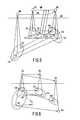
- Figures 5, 6 represent two accessing mechanisms.
- Figure 1 is a sample flow map showing tools and data useage. Data flows from left to right in this notation. In this example, blocks 20, 22..30 represent tools. Examples of such tool functions have been given under A-G, supra, for a silicon compiler. In other engineering systems, corresponding subprocesses would be obvious to the person of average skill. Generally, the tool itself is a computer program for effecting such tool function. Each run of a tool may generate an instance of the representation type following the tool in question in the Figure. Each tool may generate many kinds and versions of the same representation type, for example, in that eliminating a bug or problem at a particular level would lead to corresponding different instances at each next following level in the lineage. Any instance, if applicable, may be of one alternative type of a set of types, for example, either before or after the problem has been removed. Moreover, any tool itself may yield instances that have different character, for example in that the partial results are classified into disjunct representations or results. Now, blocks 32..42 represent such instances. Thus, running of
tool 20 generates representations of the type symbolized byblock 32. Running oftool 28 generates representations of the type symbolized by block 40. For simplicity, each running or execution of the same tool is presumed to generate only a single category of representation. Alternatively,such blocks 32..42 are presumed to contain all representations produced by the flow caused by running its associated tool. Examples are that a particular tool used in CAD of VLSI-circuitry may produce either a schematic or a net-list or both each time the tool is executed. A schematic is a two-dimensional drawing showing subsystems as blocks plus their interconnections in the form of lines. A net-list gives, starting from a first sub-system interconnection pin all other pins (on the same or on another sub-system) to which the former pin is connected. - Another example would be that a simulator tool produces both an output waveform and an ASCII-coded character log file. Which one of the latter two be needed, is entirely determined by the selected viewing tool so that the details of the system are transparent to a user. Hereinafter, the combination of a tool block and its next-following output representational block is made into a node of a derivational first directed-acyclic-graph (flow-graph). A set of output representations produced by a single tool run is regarded hereinafter as a single entity, regardless of their accidental representations. Physically, such multiple representations may thereafter be distributed among multiple files, each pertaining to an associated respective node. It should be noted that the distinction between different representations is determined by convention and technology, rather than by essence or principle. Likewise, Figure 1 may be changed in that the various data representations of running a particular tool be each assigned a given box, e.g. in that
box 36 had been divided into box 36A, leading exclusively totool box 28, and another box 36B leading exclusively to tool box 30 (assuming that each of the latter tools need only a single data representation, which would be unique and mutually exclusive betweentool boxes 28, 30). It should be noted that Figure 1 should show all items and links with respect to the tools shown. Thus,tool 20 only outputs to block 32.Tool 24 exclusively feeds on data from that inblock 32 and exclusively outputs to block 36. Now, Figure 1 mathematically is a tree. Alternatively, the graph could have two source nodes linking to a single destination node. Instead ofsource node 24/36 linking by respective links todestination nodes 28/40, 30/42, in another circumstance bothnodes 22/34 and 24/36 could as source nodes be linked todestination node 28/40. In this way a generalized directed-acyclic-graph would be procuded. In a database representation the linking could be by tethering pointers in the data pertaining to a particular flow node. The pointer may be an address, a logical name, or some other entity, and would distinguish between a source flow node and a destination flow node in an elementary way. - Figure 2 shows a sample data derivation graph which might occur, given the flow graph of Figure 1. No tools are shown. Each letter in Figure 2 represents an instance of an associated representation in Figure 1. Thus, there are two instances A of
representation 32, four instances B ofrepresentation 34, four instances C ofrepresentation 36, and nine instances of representation 40.Tools - On a specific technical level, the tools and data generated thereby may be as follows for a VLSI CAD environment:
- 20:
- schematic editor, produces schematic 32
- 22:
- lay-out processor which produces lay-
out 34 - 24:
- simulator module produces
simulation result 36 - 26:
- postprocessor produces one or more tapes that could be fed into a plotter or the like (38)
- 28:
- viewer module
- 30:
- read log file which may contain error messages of errors incurred in simulation, or other data.
- By way of simplification, the graph of Figure 2, like the one of Figure 1, is a tree, which, in a similar way could be a more generalized directed-acyclic-graph. Furthermore, it could as an alternative to an electronic engineering process, relate to a mechanical engineering process, a software engineering process, or the development of a process itself, the latter process then being useable for manufacturing, or for developing one of the earlier described products of electrical, mechanical or software engineering. In a mechanical engineering process, successive analysis steps could relate to kinematic analysis, structural analysis, and styling. In software engineering, a hierarchy of programs, program modules, and routines may be detailed in successive steps. in designing a process, input commodities, intermediate buffering and critical time paths may be detailed in successive steps. The present invention in each of these cases would provide easy accessing and organizing of the product describing data.
- Figure 3 shows the logical structure of the data used by a preferred elementary embodiment of the present invention. As is common practice in describing database designs, the data structure is described at the entity type level (rather than entity instance level) and at the relationship type level. Thus, any single symbol, such as a box or a diamond, explained hereinafter, can correspond to an
arbitrary number 1, 2 ... of database instances of that particular type. - The described logical data structure can be converted into a physical data structure (records, tables, attributes, pointers, etcetera) and augmented with means for reading, writing, updating, managing, and displaying the data in completely conventional ways.
- It should be noted that in a typical implementation of this or any other embodiment of the invention, these structures will be supplemented with additional structures dealing with the various functional extensions without departing from the present inventive concept. Such additional structures may be, for example, (parts of) hierarchies used in describing the design data or information, characterizing the allowed or selected invocation options for individual flow nodes. Form the logical data organization shown, the physical organization, such as logical/physical addressing, labeling, referencing between records, displaying, inputting, outputting and various other physical-directed operations may be effected in completely conventional way. Of course, the structures shown are only minute examples of databases that may exhibit extreme degrees of complexity and massive storage requirements without departing from the present inventive concept. In particular, Figure 3 shows an entity/relationship diagram defining the structure of an elementary database for storing both the flow map information and the administrative data about the product describing data being managed as required by the method of this invention. The boxes represent entity types, the diamonds represent relationship types between the connected entity types and the labels "1" and "M"="many" along the connections between diamonds and boxes provide cardinality information about the associated relationship types. For more information on database schemas in general and the Entity/Relationship notation in particular, see "An Introduction to Database Systems",
Volume 1, C.J. Date, Addison-Wesley, 1986 (4th edition). -
Block 50 represents engineering subprocesses which require and/or produce product describing data. As explained, only a single box is shown, which can represent multiple instances. These subprocesses are linked among each other by dependence flow links (52), thereby forming a data flow graph of the engineering process. Each dependence flow link (52) is associated viarelationships elements relationships -
Block 54 represents the data set generated by each execution of a particular engineering subprocess (50).Block 54 may again represent many instances.Relationship 64 links each data set to the engineering subprocess (50) by which it was generated. The cardinality M (the different letters M can have completely different values in practice) indicates that one particular process may in principle be able to generate many data sets. The data sets 54 are linked via derivation links (56). Each derivation link (56) is associated viarelationships entity type 54 which respectively represent the source and destination of the derivation link (56). Together,elements - The
final relationship 70 associated each derivation link 56 with exactly oneflow link 52, thereby representing how the derivation link between two data sets is associated with the flow of data between two engineering subprocesses. It is worth nothing thatrelationship 70 serves to facilitate the maintainability of the database and can be omitted if the database integrity is maintained by suitable algorithms whenever the database is updated. - The information linking each data set entity (54) to the corresponding product describing data in a data storage system are not shown because this information depends on the physical and organizational details of the storage system and because this link can be implemented by any competent person familiar with database technology. Typically this would involve recording the network nodes, disks, directories, file names, etcetera of the product describing data for all data sets.
- Figure 4 shows an entity/relationship diagram defining the structure of a more extensive database for storing the flow map information and the administrative data about the product describing data being managed. Compared to the previous Figure, Figure 4 contains additional information about how the product describing data is partitioned into representations (e.g. "netlist", "schematic", "log file") in an electronic engineering environment. Although the basis structure of Figure 4 is comparable to Figure 3 and as such would require little explanation, various additions and refinements produce improved facilities and properties.
-
Block 72 represents engineering subprocesses which each require a set of input representations in order to produce a set of output representations. Representations are fed into a subprocess via input slots (74). Representations generated by the execution of a subprocess become available at output slots (80). Relationship types 84 and 88 respectively link each input and output slot to the corresponding engineering subprocess (72).Relationship type 86 indicates which input slots (74) are connected to which output slot (80). Together,elements -
Block 78 represents an execution of the engineering subprocess (72) to which it is linked viarelationship type 94. Each execution (78) of an engineering subprocess generates an number of representations (82) to which it is linked viarelationship type 98. Each of these representations is associated with the output slot (80) by means of which it was produced viarelationship type 92. Each execution (78) of an engineering subprocess (72) uses the set of representations (82) to which it is indirectly linked viarelationship 100, therepresentation usage entity 76 andrelationship 96. From the inverse point of view, eachrepresentation 82 is used by the set of engineering subprocess executions (78) to which it is indirectly linked viarelationship 96, the representation usage entity (76) andrelationship 100. Each representation usage entity (76), representing the usage a given representation (82) within a particular engineering subprocess execution (78), is associated with the input slot (74) in which it was used viarelationship 90. Together,elements - As in Figure 3, the information linking each representation (82) to the corresponding product describing information in a data storage system is not shown because this information depends on the details of the storage system and because this link can be implemented by any competent person familiar with database technology.
- In addition to the above, tools may occur in quite simple form, in that they require one upstream tool to have been executed and thereupon allow one downstream tool to be excecuted. A more complicated tool may have two inputs and one output. Such tools may be serialized in that the output of the first operates as one of the two inputs of the second. Collectively, they would then function as a three-input, two-output composite tool. On the other hand, the output of a preceding tool may be used in two succeeding tools in parallel. The latter could have their outputs, in turn, feed only one single output tool. The combination of the four last-mentioned tools could, alternatively be represented as a single-input-single-output (compound) tool.
- The method provides a model of the data flow between the various engineering activities needed to produce and validate the data. This model is used to store and retrieve the generated data: the data is stored according to a new data schema (logical data structure) and retrieved using a new browsing/access technique. An extension of the invention involves using the data flow information to determine the user's privileges (e.g. visibility, usage and update rights) with respect to the data being managed.
- The new insight on which the invention is based can be clarified by dividing the control information which the system needs into three distinct levels:
- 1) "Flow-type definition level"
This part of the data schema describes which programs/subprocess steps are available when setting up one or more engineering processes. In practice this level should know which programs are available, how many "inputs" and "outputs" each program/step has (optionally with typing information). Example: a format conversion program accepts one input file and uses this to produce one output file of a different type. In Figures 3, 4, for reasons of clarity this level has not been visualized. - 2) "Flow-map definition level"
This part of the data schema describes how the various flow-types (defined in level 1) are interconnected, thereby forming a map of a particular engineering process. The typing information oflevel 1 can be used to check the interconnections of level 2. This level corresponds to the left-hand halves of Figures 3, 4. - 3) "Data and flow run level"
This part of the data schema describes individual runs (executions) of flows (as defined in level 2) along with the data these produced. Thus level 3 is basically a database about the units of data produced by the engineering process while simultaneously acting as a record of all major activities with this process. The flow-map information of level 2 can be used as a very rigorous form of type checking: it can be used to prevent the running of tools on inappropriate data units. This level corresponds to the right-hand halves of Figures 3, 4. - Notably,
levels 1 and 2 of the resulting database are respectively filled when the system is configured while level 3 stores data about what is happening during the design process being supported. - Our invention is different from existing solutions in the way it uses a data flow model of the data generating process as the primary source of information about the nature of the data generated by the process itself. Overall advantages of this general principle and our particular technique are with respect to coherence:
The system provides close integration between functionality regarding the automation and control of the engineering process on the one hand and the functionality regarding the management of the generated data on the other hand.
Furthermore, from a pragmatic point of view: - * less effort needed to configure a system,
- * less data need to be supplied about what the individual units of data represent,
- * user interface can present data to users in a way consistent with the activities which are relevant at that time. Example: the code needed to integrate an individual tool into the system can be limited to what is required to handle idiosyncracies of the tool. issues common to all tools are handled by "filling tables" describing the tool and its links to its environment.
- Accuracy:
The system uses a more accurate model of the significance c.q. structure of the data being managed than existing systems. From a pragmatic point of view the concepts with which the system communicates to the user are more powerful and close to the way the user views the data (human factors issue). The accuracy allows the system to provide more functionality, because the system knowns more about what the data being managed "means" to the user.
Example: existing systems use the concept of "versioning" for different situations which should actually be also differently. In effect, the present method and system provides the facility for such differentiation. - Flexibility: The system can handle a wider variety of engineering processes than existing systems.
Example: the access/browsing technique works equally well on data describing the product itself as on auxiliary data, e.g. test data. - Simplicity: The system uses fewer internal concepts than an existing system which extend to provide comparable functionality. This tends to reduce development and maintenance costs for the system and potentially reduces the training effort for end-users. The system should be slightly faster for similar reasons.
Example: unlike previous systems, the technique does not need to maintain separate sets of information for describing the classification of the data and for describing the history of the engineering process. These are handled by the same set of concepts. - It is possible that output of an engineering subprocess is used as an input of the same subprocess. Such a subprocess may be called an editor. An example is a simple text editor, in which the text, produced in a previous edit-session, can be used in a new edit-session to produce a modified version of the original text. Likewise, various other types of data editors may be used.
- Generally, the data flow map of the engineering process forms a directed graph without loops. However, if the engineering process contains an editor the directed graph contains a loop. This loop requires special treatment to make it possible to execute an editor without input, in order to produce the first version of the output, thereby making the data flow in the loop optimal.
- Various other useful features are: the invention allows the nesting of flows. Although this might appear a trivial issue, it allows for the construction of improved user interfaces. For example, in a preprocessor -tool- postprocessor sequence, the tool becomes hidden by the automation. Particular advantages of the use of the invention are that project organization is facilitated, person-to-person communication is done by making the data communicated visible, and also project management on a time/data/resource/manpower level is made easier.
- Figures 5, 6 illustrate two accessing mechanisms. In Figure 5,
line 100 indicates the dichotomy between flow graph (top) and data graph (bottom). In the flow graph, flownodes flow link 106. Here flownode 102 is the source and flownode 104 is the destination.Flow node 108 is a further source node to flownode 104 by indirect linkeage which has been shown by interruptedline 110. This latter linkeage may or may not includeflow node 102.Flow node 102 is referred to by threedata nodes Flow node 104 is referred to by threedata nodes Flow node 108 is referred to bydata nodes node 104. It is possible to a priori not select all those data nodes, for example in that one or more data nodes contain a directly detectable error. The latter have not been shown. As shown, the data nodes have a linkeage pattern that mimics the linkeage pattern of the flow nodes. Now two arbitrary further subsets of the data nodes are selected, one referring to flownode 108, one to flownode 102. For one reason or another, such as a directly detectable error,data node 112 is excluded from the auxiliary subset related to flownode 102. Now this is used to restrict the first subset ofdata nodes data node 122 in that it has not both a directly linked data source node referring to flownode 102 and also a(n indirectly) linked data source node referring to flownode 108 The restriction to the final subset (118, 120) is shown by a broken line. In any more complicated structure, the selecting mechanism would operate in comparable manner; the only differences would be the number of elements in the various sets, the number of terms in the logical AND-function combining the various auxiliary subsets, the depth of the linkeage pattern, and the various reasons leading to exclusion of elements of the respective sets. - Whereas in Figure 5 the reasoning exploits the upstream linkeage pattern, this is directed in the downstream direction in Figure 6.
Flow node 130 is directly linked as source node todestination flow node 132 and indirectly todestination flow node 134. Again, a part or whole of the indirect path may lead throughflow node 132. For selecting, first a subset referring to flownode 130 is selected, to wit,data nodes Flow node 132 is referred to bydata nodes Flow node 134 is referred to by data nodes 146 (selected in its auxiliary subset) and 148 (not selected). In this case the final subset is restricted todata node 136, because of the exclusion of data node 148 (leads to exclusion of data node 140) and the non-existence of two data nodes that would be linked as destination nodes todata source nodes - The database may comprise coupling between links, such as between
data links link 106.
Claims (15)
- A method for organizing and accessing product describing data, generated and/or used by an engineering process comprising multiple engineering subprocesses, said method comprising:a. providing a first set of flow nodes, each individual flow node representing one unique of said subprocesses;b. performing at least one flow node execution, which flow node execution represents a corresponding subprocess execution which thereby uses and/or generates respective part(s) of said product describing data;c. providing a data flow model of the engineering process by linking said flow nodes to form a first directed-acyclic-graph of which each flow link, by connecting one source flow node to one destination flow node, represents as fact that each execution of said destination flow node requires partial or complete usage of product describing data generated by exectuion of said source flow node;d. providing a second set of data nodes, each individual data node referencing one unique flow node for so representing one unique individual execution of the flow node so referenced and consequently also representing the product describing data generated by the latter unique individual execution;e. providing a model of the product describing data used and/or generated by the engineering process by linking said data nodes to form a second directed-acyclic-graph of which each data link by connecting one source data node to one destination data node, represents as fact partial or complete usage of the product describing data represented by said source data node for generating the product describing data represented by said destination data node;f. providing a mechanism for selecting from the second set of data nodes a first subset of data nodes by selecting one first particular flow node which restricts said first subset of data nodes to those data nodes which reference said first particular flow node;g. selecting an arbitrary number of auxiliary subsets of data nodes, each auxiliary subset referencing one respective further particular flow node, that is directly or indirectly linked as source flow node to said first particular flow nodes by respective associated flow link or links in said first directed-acyclic-graph, for so providing a mechanism for reducing said first subset of data nodes to form a final set of data nodes in that from said first subset of data nodes said final subset of data nodes comprises only those data nodes for which the engineering subprocess execution represented thereby directly or indirectly had used the product describing data represented by one of the data nodes in each respective individual auxiliary subset of data nodes;h. accessing the product describing data represented by said final subset of data nodes using mapping information relating individual data nodes to product describing data residing within a data storage system.
- A method as in Claim 1, furthermore comprising:
g'. selecting a second arbitrary number of second auxiliary subsets of data nodes, each second auxiliary subset referencing one respective second particular flow node, that is directly or indirectly linked as destination flow node to said first particular flow node by respective associated further flow link or links in said first directed-acyclic-graph, for so providing a further mechanism for reducing said first subset of data nodes to said final set of data nodes in that said final subset of data nodes comprises only those data nodes for which also the engineering subprocess execution represented thereby directly or indirectly had been used for generating the product describing data represented by one of the data nodes in each respective individual second auxiliary subset of data nodes. - A method as in Claim 1 or 2, wherein each particular data link is coupled to exactly one flow link in that the product describing data represented by either end node of said data link originate from an execution of the subprocesses corresponding to the respective end nodes of the thereto coupled flow link.
- A method as in Claim 1, 2 or 3, wherein the first directed-acyclic-graph is extended to an extended directed-acyclic-graph with information about the way in which the product describing data, produced and used, respectively, by executions of the engineering subprocesses is physically partitioned into units and wherein the second directed-acyclic-graph is extended with information mapping said individual units of data residing within a storage system onto elements of the second directed-acyclic-graph.
- A method as claimed in Claim 4, wherein the flow nodes within the extended directed-acyclic-graph are provided with additional typing information representing the type of engineering subprocess of which they are an instance thereby allowing the usage of the flow nodes in the extended directed-acyclic-graph to be checked against said typing information.
- A method as in any of Claims 1 to 5, wherein a further subset of the flow nodes of the first directed-acyclic-graph is provided with information pertaining to a physical location and method of invocation of executable programs corresponding to the respective elements of said subset, thereby allowing the information in the first directed-acyclic-graph to be used to automate and/or support the execution of said executable programs.
- A method as in any of Claims 1 to 6, wherein an additional type of link is introduced interconnecting flow nodes in the first directed-acyclic-graph thereby representing non-mandatory use of product describing data by executions of the engineering subprocess corresponding to the destination node of said type of links.
- A method as in any of Claims 1 to 7, wherein the first directed-acyclic-graph forms a hierarchical model of the engineering process by linking nodes therein representing either individual engineering subprocesses or subgraphs of interlinked engineering subprocesses.
- A method as in Claim 8, wherein hierarchical description of the engineering process limits the accessibility and visibility of product describing data generated by the execution of flow nodes belonging to a particular level of the hierarchy to those users of the system with appropriate privileges for said particular level.
- A method as claimed in any of Claims 1 to 9, wherein feedback link means are added to said first directed-acyclic-graph, thereby transforming said first directed-acyclic-graph into a generalized directed graph exhibiting one or more cycles, whereby each feedback link, having exactly one source flow node and exactly one destination flow node, represents the fact that the product describing data generated by an execution of said flow node can optionally be used as input for the execution of said destination flow node, thereby providing the capability of modifying the latter product describing data an arbitrary number of times.
- A data management system comprising a physical implementation of a method as claimed in any of Claims 1 to 10, comprising storage means for storing the product describing data represented by said data nodes, graphs, instances and links, input means for inputting further product describing data and user requests and output means for under control of a user request selectively outputting and/or displaying subsets of product describing data stored in said storage means.
- A data management system as claimed in Claim 11, wherein said product describing data is electronic engineering data.
- A system as claimed in Claim 11, wherein said product describing data is mechanical engineering data.
- A system as claimed in Claim 11, wherein said product describing data is software engineering data.
- A system as claimed in Claim 11, wherein said product describing data is information describing an engineering process.
Priority Applications (4)
| Application Number | Priority Date | Filing Date | Title |
|---|---|---|---|
| DE69031758T DE69031758T2 (en) | 1990-04-13 | 1990-04-13 | Process for organizing and accessing product descriptive data in connection with a technical process |
| EP90200919A EP0451371B1 (en) | 1990-04-13 | 1990-04-13 | A method for organizing and accessing product describing data pertaining to an engineering process |
| JP3106447A JPH07121554A (en) | 1990-04-13 | 1991-04-12 | Product description data organization and access method regarding engineering process |
| US08/232,856 US5392220A (en) | 1990-04-13 | 1994-04-25 | Method and system for organizing data |
Applications Claiming Priority (1)
| Application Number | Priority Date | Filing Date | Title |
|---|---|---|---|
| EP90200919A EP0451371B1 (en) | 1990-04-13 | 1990-04-13 | A method for organizing and accessing product describing data pertaining to an engineering process |
Publications (2)
| Publication Number | Publication Date |
|---|---|
| EP0451371A1 true EP0451371A1 (en) | 1991-10-16 |
| EP0451371B1 EP0451371B1 (en) | 1997-11-26 |
Family
ID=8204990
Family Applications (1)
| Application Number | Title | Priority Date | Filing Date |
|---|---|---|---|
| EP90200919A Expired - Lifetime EP0451371B1 (en) | 1990-04-13 | 1990-04-13 | A method for organizing and accessing product describing data pertaining to an engineering process |
Country Status (4)
| Country | Link |
|---|---|
| US (1) | US5392220A (en) |
| EP (1) | EP0451371B1 (en) |
| JP (1) | JPH07121554A (en) |
| DE (1) | DE69031758T2 (en) |
Cited By (11)
| Publication number | Priority date | Publication date | Assignee | Title |
|---|---|---|---|---|
| WO1998053412A2 (en) * | 1997-05-23 | 1998-11-26 | Koninklijke Philips Electronics N.V. | Control of mass-produced discrete product, involving multiple physical modules |
| WO2000002153A1 (en) * | 1998-07-02 | 2000-01-13 | Ita Software, Inc. | Travel planning system |
| US6275808B1 (en) | 1998-07-02 | 2001-08-14 | Ita Software, Inc. | Pricing graph representation for sets of pricing solutions for travel planning system |
| US6295521B1 (en) | 1998-07-02 | 2001-09-25 | Ita Software, Inc. | Travel planning system |
| EP1189156A1 (en) * | 2000-08-03 | 2002-03-20 | FIATAVIO S.p.A. | Computer-assisted design system |
| US6377932B1 (en) | 1998-07-02 | 2002-04-23 | Ita Software, Inc. | Rules validation for travel planning system |
| US6381578B1 (en) | 1998-07-02 | 2002-04-30 | Ita Software, Inc. | Factored representation of a set of priceable units |
| US6609098B1 (en) | 1998-07-02 | 2003-08-19 | Ita Software, Inc. | Pricing graph representation for sets of pricing solutions for travel planning system |
| US6801226B1 (en) | 1999-11-01 | 2004-10-05 | Ita Software, Inc. | Graphical user interface for travel planning system |
| US7340403B1 (en) | 1999-11-01 | 2008-03-04 | Ita Software, Inc. | Method, system, and computer-readable medium for generating a diverse set of travel options |
| US7340402B1 (en) | 1999-11-01 | 2008-03-04 | Ita Software, Inc. | Generating a diverse set of travel options |
Families Citing this family (44)
| Publication number | Priority date | Publication date | Assignee | Title |
|---|---|---|---|---|
| US5493490A (en) * | 1992-05-05 | 1996-02-20 | Clear With Computers, Inc. | Electronic proposal preparation system for selling vehicles |
| JP2724082B2 (en) * | 1992-12-18 | 1998-03-09 | シャープ株式会社 | Data analysis support system for VLSI process |
| JP3202845B2 (en) * | 1993-09-27 | 2001-08-27 | 富士通株式会社 | Electronic circuit design data management system |
| US5671360A (en) * | 1995-01-20 | 1997-09-23 | International Business Machines Corporation | Project management tool implementing authority for a people oriented work environment tool |
| US7133846B1 (en) * | 1995-02-13 | 2006-11-07 | Intertrust Technologies Corp. | Digital certificate support system, methods and techniques for secure electronic commerce transaction and rights management |
| CA2683230C (en) * | 1995-02-13 | 2013-08-27 | Intertrust Technologies Corporation | Systems and methods for secure transaction management and electronic rights protection |
| US7133845B1 (en) * | 1995-02-13 | 2006-11-07 | Intertrust Technologies Corp. | System and methods for secure transaction management and electronic rights protection |
| US7095854B1 (en) * | 1995-02-13 | 2006-08-22 | Intertrust Technologies Corp. | Systems and methods for secure transaction management and electronic rights protection |
| US6157721A (en) * | 1996-08-12 | 2000-12-05 | Intertrust Technologies Corp. | Systems and methods using cryptography to protect secure computing environments |
| US6948070B1 (en) | 1995-02-13 | 2005-09-20 | Intertrust Technologies Corporation | Systems and methods for secure transaction management and electronic rights protection |
| US20060206397A1 (en) * | 1995-02-13 | 2006-09-14 | Intertrust Technologies Corp. | Cryptographic methods, apparatus and systems for storage media electronic right management in closed and connected appliances |
| US6658568B1 (en) * | 1995-02-13 | 2003-12-02 | Intertrust Technologies Corporation | Trusted infrastructure support system, methods and techniques for secure electronic commerce transaction and rights management |
| US5892900A (en) | 1996-08-30 | 1999-04-06 | Intertrust Technologies Corp. | Systems and methods for secure transaction management and electronic rights protection |
| US7143290B1 (en) * | 1995-02-13 | 2006-11-28 | Intertrust Technologies Corporation | Trusted and secure techniques, systems and methods for item delivery and execution |
| US5943422A (en) | 1996-08-12 | 1999-08-24 | Intertrust Technologies Corp. | Steganographic techniques for securely delivering electronic digital rights management control information over insecure communication channels |
| US7124302B2 (en) * | 1995-02-13 | 2006-10-17 | Intertrust Technologies Corp. | Systems and methods for secure transaction management and electronic rights protection |
| JPH08241342A (en) * | 1995-03-02 | 1996-09-17 | Matsushita Electric Ind Co Ltd | Method and device for design process recording |
| US6086619A (en) * | 1995-08-11 | 2000-07-11 | Hausman; Robert E. | Apparatus and method for modeling linear and quadratic programs |
| JPH09512377A (en) * | 1995-08-18 | 1997-12-09 | インターナシヨナル・ビジネス・マシーンズ・コーポレーシヨン | Method and apparatus for process and project management computer systems |
| US5799297A (en) * | 1995-12-15 | 1998-08-25 | Ncr Corporation | Task workflow management system and method including an external program execution feature |
| US20060265337A1 (en) * | 1996-02-26 | 2006-11-23 | Graphon Corporation | Automated system for management of licensed digital assets |
| US20010011253A1 (en) * | 1998-08-04 | 2001-08-02 | Christopher D. Coley | Automated system for management of licensed software |
| US6865524B1 (en) * | 1997-01-08 | 2005-03-08 | Trilogy Development Group, Inc. | Method and apparatus for attribute selection |
| US7062500B1 (en) * | 1997-02-25 | 2006-06-13 | Intertrust Technologies Corp. | Techniques for defining, using and manipulating rights management data structures |
| US5920861A (en) | 1997-02-25 | 1999-07-06 | Intertrust Technologies Corp. | Techniques for defining using and manipulating rights management data structures |
| US7092914B1 (en) * | 1997-11-06 | 2006-08-15 | Intertrust Technologies Corporation | Methods for matching, selecting, narrowcasting, and/or classifying based on rights management and/or other information |
| US5933831A (en) * | 1998-01-09 | 1999-08-03 | Lsi Logic Corporation | Viewing entity relationship diagrams using hyperlinks |
| US6792542B1 (en) * | 1998-05-12 | 2004-09-14 | Verance Corporation | Digital system for embedding a pseudo-randomly modulated auxiliary data sequence in digital samples |
| US6263476B1 (en) * | 1998-10-09 | 2001-07-17 | Agilent Technologies | Method and apparatus for selecting targeted components in limited access test |
| US7243236B1 (en) * | 1999-07-29 | 2007-07-10 | Intertrust Technologies Corp. | Systems and methods for using cryptography to protect secure and insecure computing environments |
| US20020010598A1 (en) * | 1999-12-18 | 2002-01-24 | Johnson Jerome Dale | System and method for providing configuration and sales information to assist in the development of insurance plans |
| US6839749B1 (en) * | 2000-07-10 | 2005-01-04 | International Business Machines Corporation | Network representation and manipulation thereof |
| DE10131438B4 (en) * | 2001-06-29 | 2005-06-02 | Daimlerchrysler Ag | Process for developing a technical component |
| EP1300757A1 (en) * | 2001-10-02 | 2003-04-09 | Sun Microsystems, Inc. | Shareable installation hierarchies |
| US20040117267A1 (en) * | 2002-12-13 | 2004-06-17 | Kilburn Mary Jo | Engineering data interface and electrical specification tracking and ordering system |
| CN1713192A (en) * | 2004-06-25 | 2005-12-28 | 国际商业机器公司 | Method and device for processing logic mode establishment and carrying out |
| US7437277B2 (en) * | 2005-08-11 | 2008-10-14 | International Business Machines Corporation | Model independent simulation |
| US8302042B2 (en) * | 2006-07-24 | 2012-10-30 | Oasys Design Systems | Generating a convergent circuit design from a functional description using entities having access to the functional description and to physical design information |
| US8412548B2 (en) * | 2007-11-27 | 2013-04-02 | International Business Machines Corporation | Linked decision nodes in a business process model |
| US8321841B2 (en) * | 2008-01-08 | 2012-11-27 | International Business Machines Corporation | Validation framework for service oriented architecture (SOA) application adoption |
| US8793568B2 (en) * | 2011-02-22 | 2014-07-29 | Accenture Global Services Limited | Page designer with customization constraints |
| US9311623B2 (en) * | 2012-02-09 | 2016-04-12 | International Business Machines Corporation | System to view and manipulate artifacts at a temporal reference point |
| EP2990969A1 (en) * | 2014-08-26 | 2016-03-02 | Dassault Systèmes | Criterion for sequential update |
| CN113590569B (en) * | 2021-07-28 | 2023-10-24 | 西安航天动力研究所 | Main model system of liquid rocket engine data and construction access method |
Citations (1)
| Publication number | Priority date | Publication date | Assignee | Title |
|---|---|---|---|---|
| EP0231594A2 (en) * | 1986-01-22 | 1987-08-12 | Mts Systems Corporation | Interactive multilevel hierarchical data flow programming system |
Family Cites Families (4)
| Publication number | Priority date | Publication date | Assignee | Title |
|---|---|---|---|---|
| US4663704A (en) * | 1984-12-03 | 1987-05-05 | Westinghouse Electric Corp. | Universal process control device and method for developing a process control loop program |
| US5150308A (en) * | 1986-09-12 | 1992-09-22 | Digital Equipment Corporation | Parameter and rule creation and modification mechanism for use by a procedure for synthesis of logic circuit designs |
| US4835730A (en) * | 1987-02-27 | 1989-05-30 | Adept Technology, Inc. | Database driven robot programming system and method |
| US5005119A (en) * | 1987-03-02 | 1991-04-02 | General Electric Company | User interactive control of computer programs and corresponding versions of input/output data flow |
-
1990
- 1990-04-13 DE DE69031758T patent/DE69031758T2/en not_active Expired - Fee Related
- 1990-04-13 EP EP90200919A patent/EP0451371B1/en not_active Expired - Lifetime
-
1991
- 1991-04-12 JP JP3106447A patent/JPH07121554A/en active Pending
-
1994
- 1994-04-25 US US08/232,856 patent/US5392220A/en not_active Expired - Fee Related
Patent Citations (1)
| Publication number | Priority date | Publication date | Assignee | Title |
|---|---|---|---|---|
| EP0231594A2 (en) * | 1986-01-22 | 1987-08-12 | Mts Systems Corporation | Interactive multilevel hierarchical data flow programming system |
Non-Patent Citations (3)
| Title |
|---|
| IEEE SOFTWARE, vol. 3, no. 3, May 1986, pages 27-39, New York, US; G. ARANGO et al.: "TMM: Software Maintenance by Transformation" * |
| PROCEEDINGS OF THE 1987 IEEE INTERNATIONAL CONFERENCE ON COMPUTER DESIGN: VLSI IN COMPUTERS AND PROCESSORS, 5-8 October 1987, pages 407-412, New York, US; Z. MEHMOOD et al.: "IDEAS - An Integrated Design Automation System" * |
| PROCEEDINGS OF THE EIGHTH INTERNATIONAL CONFERENCE ON COMPUTERS AND COMMUNICATION, 22-24 March 1989, pages 332-336, Scottsdale, Arizona, US; J. WANG et al.: "Software Performance Analysis Using a Graphic Modeling Technique" * |
Cited By (14)
| Publication number | Priority date | Publication date | Assignee | Title |
|---|---|---|---|---|
| WO1998053412A2 (en) * | 1997-05-23 | 1998-11-26 | Koninklijke Philips Electronics N.V. | Control of mass-produced discrete product, involving multiple physical modules |
| WO1998053412A3 (en) * | 1997-05-23 | 1999-02-25 | Koninkl Philips Electronics Nv | Control of mass-produced discrete product, involving multiple physical modules |
| US6377932B1 (en) | 1998-07-02 | 2002-04-23 | Ita Software, Inc. | Rules validation for travel planning system |
| US6275808B1 (en) | 1998-07-02 | 2001-08-14 | Ita Software, Inc. | Pricing graph representation for sets of pricing solutions for travel planning system |
| US6295521B1 (en) | 1998-07-02 | 2001-09-25 | Ita Software, Inc. | Travel planning system |
| WO2000002153A1 (en) * | 1998-07-02 | 2000-01-13 | Ita Software, Inc. | Travel planning system |
| US6381578B1 (en) | 1998-07-02 | 2002-04-30 | Ita Software, Inc. | Factored representation of a set of priceable units |
| US6609098B1 (en) | 1998-07-02 | 2003-08-19 | Ita Software, Inc. | Pricing graph representation for sets of pricing solutions for travel planning system |
| US8571903B1 (en) | 1998-07-02 | 2013-10-29 | Google Inc. | Pricing graph representation for sets of pricing solutions for travel planning system |
| US6801226B1 (en) | 1999-11-01 | 2004-10-05 | Ita Software, Inc. | Graphical user interface for travel planning system |
| US7340403B1 (en) | 1999-11-01 | 2008-03-04 | Ita Software, Inc. | Method, system, and computer-readable medium for generating a diverse set of travel options |
| US7340402B1 (en) | 1999-11-01 | 2008-03-04 | Ita Software, Inc. | Generating a diverse set of travel options |
| US8266547B2 (en) | 1999-11-01 | 2012-09-11 | Google Inc. | Graphical user interface for travel planning system |
| EP1189156A1 (en) * | 2000-08-03 | 2002-03-20 | FIATAVIO S.p.A. | Computer-assisted design system |
Also Published As
| Publication number | Publication date |
|---|---|
| JPH07121554A (en) | 1995-05-12 |
| EP0451371B1 (en) | 1997-11-26 |
| DE69031758D1 (en) | 1998-01-08 |
| DE69031758T2 (en) | 1998-05-28 |
| US5392220A (en) | 1995-02-21 |
Similar Documents
| Publication | Publication Date | Title |
|---|---|---|
| US5392220A (en) | Method and system for organizing data | |
| AU648533B2 (en) | Software engineering facility | |
| Lee | Information modeling: From design to implementation | |
| US4860204A (en) | Computer based workstation for development of graphic representation of computer programs | |
| Engelke et al. | Integrated manufacturing modeling system | |
| van den Hamer et al. | A data flow based architecture for CAD frameworks | |
| Lee et al. | An overview of information modeling for manufacturing systems integration | |
| Cleetus | Modeling evolving product data for concurrent engineering | |
| Anquetil et al. | Modular Moose: A new generation software reverse engineering environment | |
| Morris et al. | Database management systems in engineering | |
| Ma et al. | Computer-assisted formulation of linear programs | |
| Ruehr | A Survey of Extensions to APL | |
| Stucky et al. | INCOME/STAR: Process model support for the development of information systems | |
| Lindsjørn et al. | Database concepts discussed in an object oriented perspective | |
| Martins | Human-Computer Interaction in Smart Manufacturing Systems: reactive and adaptive UIs | |
| Macdonald | Automating information engineering | |
| Yu et al. | Representability of design objects by ancestor-controlled hierarchical specifications | |
| Wiederhold et al. | Layering an engineering information system. | |
| Vergeest et al. | Flexible communication between dissimilar CAD/CAM systems | |
| Morris | Database management systems in engineering | |
| Heerjee et al. | Retrospective software specification | |
| Granacki et al. | A Component Library Management System and Browser | |
| Bayer et al. | Integration tools for supporting incremental modifications within design processes in chemical engineering | |
| Zanella et al. | Design management additions to the Octtools environment | |
| Chou et al. | An OOA model with system function specifications |
Legal Events
| Date | Code | Title | Description |
|---|---|---|---|
| PUAI | Public reference made under article 153(3) epc to a published international application that has entered the european phase |
Free format text: ORIGINAL CODE: 0009012 |
|
| AK | Designated contracting states |
Kind code of ref document: A1 Designated state(s): AT BE CH DE DK ES FR GB GR IT LI LU NL SE |
|
| RBV | Designated contracting states (corrected) |
Designated state(s): DE FR GB IT |
|
| 17P | Request for examination filed |
Effective date: 19920415 |
|
| 17Q | First examination report despatched |
Effective date: 19950929 |
|
| GRAG | Despatch of communication of intention to grant |
Free format text: ORIGINAL CODE: EPIDOS AGRA |
|
| GRAH | Despatch of communication of intention to grant a patent |
Free format text: ORIGINAL CODE: EPIDOS IGRA |
|
| GRAH | Despatch of communication of intention to grant a patent |
Free format text: ORIGINAL CODE: EPIDOS IGRA |
|
| GRAA | (expected) grant |
Free format text: ORIGINAL CODE: 0009210 |
|
| AK | Designated contracting states |
Kind code of ref document: B1 Designated state(s): DE FR GB IT |
|
| PG25 | Lapsed in a contracting state [announced via postgrant information from national office to epo] |
Ref country code: IT Free format text: LAPSE BECAUSE OF FAILURE TO SUBMIT A TRANSLATION OF THE DESCRIPTION OR TO PAY THE FEE WITHIN THE PRESCRIBED TIME-LIMIT;WARNING: LAPSES OF ITALIAN PATENTS WITH EFFECTIVE DATE BEFORE 2007 MAY HAVE OCCURRED AT ANY TIME BEFORE 2007. THE CORRECT EFFECTIVE DATE MAY BE DIFFERENT FROM THE ONE RECORDED. Effective date: 19971126 |
|
| REF | Corresponds to: |
Ref document number: 69031758 Country of ref document: DE Date of ref document: 19980108 |
|
| ET | Fr: translation filed | ||
| RAP4 | Party data changed (patent owner data changed or rights of a patent transferred) |
Owner name: KONINKLIJKE PHILIPS ELECTRONICS N.V. |
|
| REG | Reference to a national code |
Ref country code: FR Ref legal event code: CD |
|
| PLBE | No opposition filed within time limit |
Free format text: ORIGINAL CODE: 0009261 |
|
| STAA | Information on the status of an ep patent application or granted ep patent |
Free format text: STATUS: NO OPPOSITION FILED WITHIN TIME LIMIT |
|
| 26N | No opposition filed | ||
| PGFP | Annual fee paid to national office [announced via postgrant information from national office to epo] |
Ref country code: FR Payment date: 20010423 Year of fee payment: 12 |
|
| PGFP | Annual fee paid to national office [announced via postgrant information from national office to epo] |
Ref country code: GB Payment date: 20010430 Year of fee payment: 12 |
|
| PGFP | Annual fee paid to national office [announced via postgrant information from national office to epo] |
Ref country code: DE Payment date: 20010620 Year of fee payment: 12 |
|
| REG | Reference to a national code |
Ref country code: GB Ref legal event code: IF02 |
|
| PG25 | Lapsed in a contracting state [announced via postgrant information from national office to epo] |
Ref country code: GB Free format text: LAPSE BECAUSE OF NON-PAYMENT OF DUE FEES Effective date: 20020413 |
|
| PG25 | Lapsed in a contracting state [announced via postgrant information from national office to epo] |
Ref country code: DE Free format text: LAPSE BECAUSE OF NON-PAYMENT OF DUE FEES Effective date: 20021101 |
|
| GBPC | Gb: european patent ceased through non-payment of renewal fee |
Effective date: 20020413 |
|
| PG25 | Lapsed in a contracting state [announced via postgrant information from national office to epo] |
Ref country code: FR Free format text: LAPSE BECAUSE OF NON-PAYMENT OF DUE FEES Effective date: 20021231 |
|
| REG | Reference to a national code |
Ref country code: FR Ref legal event code: ST |