EP0450779A1 - Tape cutting apparatus - Google Patents
Tape cutting apparatus Download PDFInfo
- Publication number
- EP0450779A1 EP0450779A1 EP19910302198 EP91302198A EP0450779A1 EP 0450779 A1 EP0450779 A1 EP 0450779A1 EP 19910302198 EP19910302198 EP 19910302198 EP 91302198 A EP91302198 A EP 91302198A EP 0450779 A1 EP0450779 A1 EP 0450779A1
- Authority
- EP
- European Patent Office
- Prior art keywords
- tape
- cutter
- support member
- cutting
- cutting apparatus
- Prior art date
- Legal status (The legal status is an assumption and is not a legal conclusion. Google has not performed a legal analysis and makes no representation as to the accuracy of the status listed.)
- Granted
Links
Images


Classifications
-
- B—PERFORMING OPERATIONS; TRANSPORTING
- B65—CONVEYING; PACKING; STORING; HANDLING THIN OR FILAMENTARY MATERIAL
- B65C—LABELLING OR TAGGING MACHINES, APPARATUS, OR PROCESSES
- B65C9/00—Details of labelling machines or apparatus
- B65C9/08—Label feeding
- B65C9/18—Label feeding from strips, e.g. from rolls
- B65C9/1803—Label feeding from strips, e.g. from rolls the labels being cut from a strip
-
- B—PERFORMING OPERATIONS; TRANSPORTING
- B26—HAND CUTTING TOOLS; CUTTING; SEVERING
- B26D—CUTTING; DETAILS COMMON TO MACHINES FOR PERFORATING, PUNCHING, CUTTING-OUT, STAMPING-OUT OR SEVERING
- B26D3/00—Cutting work characterised by the nature of the cut made; Apparatus therefor
- B26D3/08—Making a superficial cut in the surface of the work without removal of material, e.g. scoring, incising
- B26D3/085—On sheet material
-
- B—PERFORMING OPERATIONS; TRANSPORTING
- B26—HAND CUTTING TOOLS; CUTTING; SEVERING
- B26D—CUTTING; DETAILS COMMON TO MACHINES FOR PERFORATING, PUNCHING, CUTTING-OUT, STAMPING-OUT OR SEVERING
- B26D3/00—Cutting work characterised by the nature of the cut made; Apparatus therefor
- B26D3/10—Making cuts of other than simple rectilinear form
-
- B—PERFORMING OPERATIONS; TRANSPORTING
- B26—HAND CUTTING TOOLS; CUTTING; SEVERING
- B26D—CUTTING; DETAILS COMMON TO MACHINES FOR PERFORATING, PUNCHING, CUTTING-OUT, STAMPING-OUT OR SEVERING
- B26D5/00—Arrangements for operating and controlling machines or devices for cutting, cutting-out, stamping-out, punching, perforating, or severing by means other than cutting
- B26D5/08—Means for actuating the cutting member to effect the cut
- B26D5/10—Hand or foot actuated means
-
- B—PERFORMING OPERATIONS; TRANSPORTING
- B26—HAND CUTTING TOOLS; CUTTING; SEVERING
- B26D—CUTTING; DETAILS COMMON TO MACHINES FOR PERFORATING, PUNCHING, CUTTING-OUT, STAMPING-OUT OR SEVERING
- B26D7/00—Details of apparatus for cutting, cutting-out, stamping-out, punching, perforating, or severing by means other than cutting
- B26D7/01—Means for holding or positioning work
- B26D7/02—Means for holding or positioning work with clamping means
- B26D7/025—Means for holding or positioning work with clamping means acting upon planar surfaces
-
- B—PERFORMING OPERATIONS; TRANSPORTING
- B41—PRINTING; LINING MACHINES; TYPEWRITERS; STAMPS
- B41J—TYPEWRITERS; SELECTIVE PRINTING MECHANISMS, i.e. MECHANISMS PRINTING OTHERWISE THAN FROM A FORME; CORRECTION OF TYPOGRAPHICAL ERRORS
- B41J11/00—Devices or arrangements of selective printing mechanisms, e.g. ink-jet printers or thermal printers, for supporting or handling copy material in sheet or web form
- B41J11/66—Applications of cutting devices
- B41J11/70—Applications of cutting devices cutting perpendicular to the direction of paper feed
- B41J11/703—Cutting of tape
-
- B—PERFORMING OPERATIONS; TRANSPORTING
- B41—PRINTING; LINING MACHINES; TYPEWRITERS; STAMPS
- B41J—TYPEWRITERS; SELECTIVE PRINTING MECHANISMS, i.e. MECHANISMS PRINTING OTHERWISE THAN FROM A FORME; CORRECTION OF TYPOGRAPHICAL ERRORS
- B41J3/00—Typewriters or selective printing or marking mechanisms characterised by the purpose for which they are constructed
- B41J3/407—Typewriters or selective printing or marking mechanisms characterised by the purpose for which they are constructed for marking on special material
- B41J3/4075—Tape printers; Label printers
-
- B—PERFORMING OPERATIONS; TRANSPORTING
- B41—PRINTING; LINING MACHINES; TYPEWRITERS; STAMPS
- B41J—TYPEWRITERS; SELECTIVE PRINTING MECHANISMS, i.e. MECHANISMS PRINTING OTHERWISE THAN FROM A FORME; CORRECTION OF TYPOGRAPHICAL ERRORS
- B41J3/00—Typewriters or selective printing or marking mechanisms characterised by the purpose for which they are constructed
- B41J3/44—Typewriters or selective printing mechanisms having dual functions or combined with, or coupled to, apparatus performing other functions
- B41J3/46—Printing mechanisms combined with apparatus providing a visual indication
-
- B—PERFORMING OPERATIONS; TRANSPORTING
- B26—HAND CUTTING TOOLS; CUTTING; SEVERING
- B26D—CUTTING; DETAILS COMMON TO MACHINES FOR PERFORATING, PUNCHING, CUTTING-OUT, STAMPING-OUT OR SEVERING
- B26D7/00—Details of apparatus for cutting, cutting-out, stamping-out, punching, perforating, or severing by means other than cutting
- B26D2007/0012—Details, accessories or auxiliary or special operations not otherwise provided for
- B26D2007/0062—Rounding off the end of self adhesive labels on tapes
-
- B—PERFORMING OPERATIONS; TRANSPORTING
- B26—HAND CUTTING TOOLS; CUTTING; SEVERING
- B26D—CUTTING; DETAILS COMMON TO MACHINES FOR PERFORATING, PUNCHING, CUTTING-OUT, STAMPING-OUT OR SEVERING
- B26D7/00—Details of apparatus for cutting, cutting-out, stamping-out, punching, perforating, or severing by means other than cutting
- B26D2007/0012—Details, accessories or auxiliary or special operations not otherwise provided for
- B26D2007/0087—Details, accessories or auxiliary or special operations not otherwise provided for for use on a desktop
-
- Y—GENERAL TAGGING OF NEW TECHNOLOGICAL DEVELOPMENTS; GENERAL TAGGING OF CROSS-SECTIONAL TECHNOLOGIES SPANNING OVER SEVERAL SECTIONS OF THE IPC; TECHNICAL SUBJECTS COVERED BY FORMER USPC CROSS-REFERENCE ART COLLECTIONS [XRACs] AND DIGESTS
- Y10—TECHNICAL SUBJECTS COVERED BY FORMER USPC
- Y10T—TECHNICAL SUBJECTS COVERED BY FORMER US CLASSIFICATION
- Y10T156/00—Adhesive bonding and miscellaneous chemical manufacture
- Y10T156/12—Surface bonding means and/or assembly means with cutting, punching, piercing, severing or tearing
-
- Y—GENERAL TAGGING OF NEW TECHNOLOGICAL DEVELOPMENTS; GENERAL TAGGING OF CROSS-SECTIONAL TECHNOLOGIES SPANNING OVER SEVERAL SECTIONS OF THE IPC; TECHNICAL SUBJECTS COVERED BY FORMER USPC CROSS-REFERENCE ART COLLECTIONS [XRACs] AND DIGESTS
- Y10—TECHNICAL SUBJECTS COVERED BY FORMER USPC
- Y10T—TECHNICAL SUBJECTS COVERED BY FORMER US CLASSIFICATION
- Y10T83/00—Cutting
- Y10T83/566—Interrelated tool actuating means and means to actuate work immobilizer
- Y10T83/5669—Work clamp
- Y10T83/576—Clamp actuating means driven by tool or tool support
- Y10T83/5769—Clamp yieldably driven by tool or tool support
-
- Y—GENERAL TAGGING OF NEW TECHNOLOGICAL DEVELOPMENTS; GENERAL TAGGING OF CROSS-SECTIONAL TECHNOLOGIES SPANNING OVER SEVERAL SECTIONS OF THE IPC; TECHNICAL SUBJECTS COVERED BY FORMER USPC CROSS-REFERENCE ART COLLECTIONS [XRACs] AND DIGESTS
- Y10—TECHNICAL SUBJECTS COVERED BY FORMER USPC
- Y10T—TECHNICAL SUBJECTS COVERED BY FORMER US CLASSIFICATION
- Y10T83/00—Cutting
- Y10T83/727—With means to guide moving work
- Y10T83/739—Positively confines or otherwise determines path of work
-
- Y—GENERAL TAGGING OF NEW TECHNOLOGICAL DEVELOPMENTS; GENERAL TAGGING OF CROSS-SECTIONAL TECHNOLOGIES SPANNING OVER SEVERAL SECTIONS OF THE IPC; TECHNICAL SUBJECTS COVERED BY FORMER USPC CROSS-REFERENCE ART COLLECTIONS [XRACs] AND DIGESTS
- Y10—TECHNICAL SUBJECTS COVERED BY FORMER USPC
- Y10T—TECHNICAL SUBJECTS COVERED BY FORMER US CLASSIFICATION
- Y10T83/00—Cutting
- Y10T83/748—With work immobilizer
- Y10T83/7487—Means to clamp work
- Y10T83/7493—Combined with, peculiarly related to, other element
- Y10T83/7513—Tool or tool support on movable clamp jaw
-
- Y—GENERAL TAGGING OF NEW TECHNOLOGICAL DEVELOPMENTS; GENERAL TAGGING OF CROSS-SECTIONAL TECHNOLOGIES SPANNING OVER SEVERAL SECTIONS OF THE IPC; TECHNICAL SUBJECTS COVERED BY FORMER USPC CROSS-REFERENCE ART COLLECTIONS [XRACs] AND DIGESTS
- Y10—TECHNICAL SUBJECTS COVERED BY FORMER USPC
- Y10T—TECHNICAL SUBJECTS COVERED BY FORMER US CLASSIFICATION
- Y10T83/00—Cutting
- Y10T83/869—Means to drive or to guide tool
- Y10T83/8759—With means to connect or disconnect tool and its drive
-
- Y—GENERAL TAGGING OF NEW TECHNOLOGICAL DEVELOPMENTS; GENERAL TAGGING OF CROSS-SECTIONAL TECHNOLOGIES SPANNING OVER SEVERAL SECTIONS OF THE IPC; TECHNICAL SUBJECTS COVERED BY FORMER USPC CROSS-REFERENCE ART COLLECTIONS [XRACs] AND DIGESTS
- Y10—TECHNICAL SUBJECTS COVERED BY FORMER USPC
- Y10T—TECHNICAL SUBJECTS COVERED BY FORMER US CLASSIFICATION
- Y10T83/00—Cutting
- Y10T83/869—Means to drive or to guide tool
- Y10T83/8798—With simple oscillating motion only
- Y10T83/8804—Tool driver movable relative to tool support
- Y10T83/8809—Fixed axis lever
Definitions
- This invention relates to a tape cutter which is capable of cutting tapes of various widths into a shape corresponding to the width.
- tape cutters which are arranged to cut an end portion of a tape strip into an arcuate shape by the use of a cutter blade having arcuate portions formed at the opposite ends thereof according to the tape width.
- the tape cutters of this sort are usually provided with a guide groove on a tape support member according to the width of the tape, along with means for restricting sideward movements of the tape strip as it is inserted into the guide groove. Accordingly, the tape strip is guided into a center position relative to the cutter blade and cut exactly into a predetermined shape by the cutter blade.
- Such a tape cutting apparatus has a problem that there have to be provided a plural number of cutter units having guide grooves of different widths and cutter blades of different lengths in order to cut tapes of different widths into a desired shape.
- the present invention has as its object the provision of a tape cutting apparatus which is capable of cutting tapes of various widths exactly into a desired shape by the use of a single cutter unit.
- a tape cutting apparatus which comprises: a tape support member for supporting a tape strip thereon; a cutter member having a cutting edge corresponding to the width of the tape strip and movable toward the tape support member to cut the tape strip; a cutter support member for supporting the cutter member movably in the tape cutting direction; a restricting member provided integrally with the cutter support member to restrict sideward movements of the tape on the tape support member; and a locking member adapted to detachably fix the restricting member on the tape support member along with the cutter support member.
- the cutting edge of the cutter member is formed in a shape conforming with the width of the tape to be cut, and the restricting member limits the sideward movements of the tape to guide the latter into a center position relative to the cutting edge for cutting the tape in a desired shape.
- the support member which supports the cutter member is formed integrally with the restricting member so that it is detachable from the fixing member together with the restricting member.
- the cutter support member presses the tape to be cut against the tape support member as the cutter member is moved against the tape to cut it.
- the tape is pressed by a pair of flexible, resilient legs positioned to engage side edges of the tape.
- the support member and the restricting member which are formed into an integral structure, can be replaced by a similar structure which is tailored to a different tape width, by an extremely simple operation.
- the cutter member which is fixed on the support member, is replaced at the same time. Accordingly, one cutter mechanism can cope with various tapes of different widths, guiding each tape into an optimum center position of the cutting edge by the tape restricting member to cut the tape accurately and easily in a desired shape.
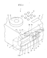
- a printing apparatus embodying the present invention which includes a letter selector dial 8 rotatably mounted on a top surface 2a of a housing 2 and having an annular dial surface 10 bearing thereon alphabetic letters, numeric figures, characters, symbols etc. to be entered.
- a group of function keys 14 which control various functions of the printing, apparatus 1, including indicating an entered letter on a liquid crystal display 16 and printing same on a transparent tape 4.
- the letter is printed by a thermal type printing head 70 which thermally transfers ink from an ink ribbon 71 onto the tape 4. In this printing operation, each character is printed as a laterally reversed image on the transparent tape 4.
- each character can be viewed as a normal image from the other side 4a of the transparent tape 4 away from the printed face 4b.
- a double-face adhesive tape 73 with a peelable tape on one side thereof is adhered on the printed face 4b of the tape 4 by a pair of presser rollers.
- the tape 4, ink ribbon 71 and adhesive tape with a peelable backing tape on one side are wound into rolls and accommodated in a common cartridge (not shown) which is detachably mounted in the printing apparatus 1.
- the printed tape 4 bonded with the double-face adhesive tape is discharged out of the housing 2 through a tape outlet 16.
- the discharged taple 4 is severed by a first cutter mechanism, namely, by a cutting mechanism 18 which is provided with a cutter blade within a casing.
- the tape is cut off when it is fed to a position where its printed portion is directly visible to the operator. Accordingly, the tape 4 can be cut off with a blank tape portion of a predetermined length posterior to the printed portion.
- a printed tape cut into a desired length for example, a strip of printed tape 4 as shown in Fig. 6.
- the above-described arrangement of the printing apparatus is substantially same as the one which is disclosed in Laid-Open European Patent Application Publication No. 0 319 209. Similar apparatus is disclosed in U.S. Patent No. 4,927,278.
- the printing apparatus further includes an end trimming mechanism 20 as a second cutter mechanism for trimming an end portion 6 of the tape 4 which has been cut off in the above-described manner.
- the end trimming mechanism 20 is provided integrally on the top side 3 of the housing 2 of the printing apparatus 1, so that the operator can readily trim the tape end whenever necessary.
- a cutter shaft 72 is provided within the housing 2 at a position downstream of the printing head 70.
- a cutter member 74 which is operable to cut off a printed portion of the tape 4.
- the cutter member 74 is constituted by a straight cutter blade 76 for severing the tape 4, and a blade holder 78 which holds the cutter blade 76.
- the blade holder 78 is provided with a bore formed vertically therethrough for receiving the cutter shaft 72, and a cutter gear portion 80 is formed on a circumferential side portion about the bore.
- the cutter member 74 is rotated by a cutter lever 82 which is rotatably mounted on a lever shaft 84 which is provided within the housing 2.
- the cutter lever 82 is integrally provided with a lever gear 86 which is formed about the lever shaft 84 for meshing engagement with the cutter gear 80. More specifically, the cutter gear 80 of the cutter member 74 and the lever gear 86 of the cutter lever 82 which meshes with the cutter gear 80 are meshed with each other through a plural number of teeth which are provided in a circumferential direction about the respective pivoting shafts to transfer rotational force in the circumferential direction without transfer of force therebetween in a direction perpendicular to the circumferential direction to permit mounting and extraction of the cutter member 74.
- the cutter lever 82 is biased in a direction inverse to the direction of arrow A by a spring 88 to abut against a side wall of the housing 2, so that the cutter blade 76 is normally retained in a position away from the tape 4.
- An anvil 90 is located on the other side of the tape 4 away from the cutter blade 76.
- the tape 4 which is fed forward by a feeder mechanism, which is not shown, and led to a path between the cutter member 74 and the anvil 90.
- a feeder mechanism which is not shown
- the cutter member 74 is rotated counterclockwise in Fig. 2 through the lever gear 86 and cutter gear 80.
- the tape 4 is pressed against the anvil 90 and severed by the cutter blade 76.
- the trimming mechanism 20 for trimming an end 6 of the tape strip which has been printed and cut off in the above-described manner such a mechanism is provided on one side wall 3 of the housing 2 as shown particularly in Fig. 3 such that part of the housing 2 forms a casing 21 for the trimming mechanism 20.
- the trimming mechanism 20 is provided with a guide groove 22 for a 12mm-wide tape and a guide groove 24 for a 16mm-wide tape side by side.
- the trimming cutter mechanisms for these tape widths are substantially the same in construction, except that the dimensions of tape guide portion and cutter blade are varied according to the tape width. Therefore, the trimming cutter mechanism is explained hereinafter by way of the mechanism for 12mm-wide tape.
- the guide groove 22 is formed by recessing the side wall 3 according to the width of the tape 4 in such a manner as to receive the tape strip 4 therein with the tape face 5 in a horizontal state.
- the guide groove 22 is internally provided with a stopper surface 25 (Fig. 9) which delimits the depth of insertion of the tape 4 by abutting engagement therewith.
- a cutter holder 30 which is positioned astride the inserted tape 4, the cutter holder 30 being provided with locking portions 32 (only one of which is shown in Fig. 4) each with a anchor pawl 34 at the lower end thereof.
- the cutter holder 30 is detachably and replaceably fixed on the casing 21 through engagement of the anchor pawls 34 with the casing 21.
- the cutter holder 30 is provided with a tape guide portion 36 which prevents the tape 4 from flexing up upon insertion into the guide groove 22, ensuring that the tape 4 is inserted in an appropriate position along the guide groove 22.
- the cutter holder 30 is further provided with a resiliently deformable portion 38, which is extended toward the stopper surface 25 substantially in parallel relation with the inserted tape 4 and provided with a hollow cover portion 40 at the fore end thereof.
- Fig. 13 shows the cover portion 40 in a transverse sectional view.
- a pair of presser legs 42 and 44 are extended obliquely from the cover portion 40 toward the tape surface 4a thereby to press the end portion 6 of the tape 4 against the guide groove 22.
- the cover portion 40 is partly notched and interiorly formed with a pendant holder portion 46 extending downwardly toward the tape surface 4a.
- a pin 48 which is inserted in the holder portion 46 is inserted into a hole 52 in a cutter blade 50 to permit the latter to rock about the pin 48.
- the pin 48 has a diameter which is smaller than that of the hole 52 in a predetermined degree.
- the cutter blade 50 is engaged with the pin 48 so that it can rock back and forth and to the left and right as indicated by arrow F in Fig. 4. Accordingly, as shown in Figs. 5 and 14, the cutter blade 50 is uniformly and stably abutted against the tape surface 4a.
- a rib 51 which is formed on the inner side of the cover portion 40 is extended toward the cutter blade 50 to prevent its dislocation from the pin 48.
- the cutter blade 50 is provided with a straight cutting edge 54 which is extended across the width of the tape 4 as shown in Figs. 4 and 5.
- Arcuate cutting edges 56 and 58 with a radius R are formed contiguously on the opposite sides of the straight cutting edge 54.
- straight auxiliary cutting edges 60 and 62 are extended contiguously from the arcuate cutting edges 56 and 58, each in a direction tangential to the circle of the radius R to form an obtuse angle ⁇ with the straight cutting edge 54.
- the angle ⁇ is set at 120° in this particular embodiment, it should suitably fall in a range between 105° and 140°.
- the angle ⁇ of the arcuate cutting edges 56 and 58 is as shown in Figs. 7 and 8, the corners of the tape 4 are trimmed into a round shape. Where the angle ⁇ is increased beyond 120°, the rounding-off effect on the trimmed tape end corners becomes less perceivable in appearance.
- the 12mm tape 4 has a tolerance t of ⁇ 0.5mm in width W. It follows that the minimum width L of the tape 4 is 11.5mm. To cope with the minimum width L, in this embodiment the afore-mentioned straight cutting edge 54 and the two arcuate cutting edges 58 and 60 are formed in a width corresponding to the minimum width L. Namely, even when trimming a tape strip of the minimum width, at least the tape end corners are rounded off by the arcuate cutting edges 56 and 58. If the straight cutting edge 54 and the arcuate cutting edges 56 and 58 are formed in a width smaller than the minimum width L, greater proportions of the tape are cut by the auxiliary cutting edges, which give an effect of straight cut rather than the rounding-off effect. Therefore, it would impair the smoothness of the rounding-off.
- the cutter blade 50 is formed by arcuately bending a straight blade of SK material, of Shore hardness of about HS60, to form arcuate bends of radius R, namely, to form the straight cutting edge 54, arcuate cutting edges 56 and 58, and auxiliary cutting edges 60 and 62.
- a cutter holder 31 and cutter blade 51 of the same construction are also provided for trimming, for example, 9mm-wide tape strips.
- the side wall 3 of the housing 2 is recessed to form, as part of the casing 21, a bottom surface 61 extending parallel with the side wall 3 at a certain depth from the surface of the side wall 3, and opposed walls 63 and 64 extending perpendicularly to the side wall 3.
- a positioning pin 65 and a transport rail 66 are projectingly provided on each of these walls 63 and 64 in face to face relation with the counterparts on the opposite wall.
- the transport rails 66 are extended parallel with the bottom surface 61, and the positioning pins 65 are projected in a greater degree than the transport rails 66.
- the trimming cutter mechanism 20 further includes a lever holder or frame 75, which is provided with rail guide 68 in sliding engagement with the positioning pins 65 and transport rails 66 for sliding movement in a direction parallel with the bottom surface 61.
- the rail guide is provided with slot-like stopper grooves 92 which are engaged with the distal end portions of the positioning pins 65.
- the lever holder 75 is provided with a plate-like locking arm 94 which is extended parallel with the bottom surface 61 and bent in the middle to form a projection 95 of U-shape in section.
- the fore end of the locking arm 94 is provided with a projection 96 toward the bottom surface 61, while a pair of locking ridges 98 and 100 are projectingly provided on the bottom surface at two spaced positions, namely, at an operable position and a retracted position.
- the locking arm 94 is formed of a resiliently deformable material, so that, if a force greater than a certain level is applied in a sliding direction, it can be moved in that direction, riding over the locking ridges 98 and 100.
- a lever 102 is rockably supporting on a rocking shaft 101 which is provided on the lever holder 75, the lever 102 being pulled toward the bottom surface 61 and normally folded into lever holder 75 by a tension spring 106 which is connected at one end to the lever 102 and at the other end to a hook portion 104 provided on the lever holder 75. When folded, the lever 102 is abutted against the projection 95 to block further sliding movement toward the bottom surface 61.
- the lever holder 75 is slid in the forward direction or toward the cutter holder 30 to assume the operable position where its forward sliding movement is stopped by abutting engagement of the positioning pins 65 with ends of the stopper grooves 92, and the lever 102 is rocked in the direction of arrow D against the action of the tension spring 106 as shown in Fig. 10, pushing down the holder portion 40 of the cutter holder 30 to move the cutter blade 50 toward the tape surface 4a.
- the lever holder 75 is slid in the rearward direction away from the cutter holder 30 to assume the retracted position where its rearward sliding movement is stopped by abutting engagement of the positioning pins 65 with the ends of the stopper grooves 92 as shown in Fig. 9, retracting the lever 102 from the cutter holder 30 so that the cutter holder 30 can be removed from the guide groove 22 from above.
- Fig. 15 is a section taken on line 15-15 of Fig. 9 and to Fig. 16, which is a bottom view of the tape guide 36 integrally formed with the cutter holder 30.
- the tape guide 36 is interiorly provided with a number of parallel guide plates 36a and 36b, of which the outermost guide plates 36a are abutted on the bottom surface 61 while the three center guide plates 36b are spaced from the bottom surface 61 by a gap which is slightly wider than the thickness of the tape 4.
- ribs 37 are formed on the bottom surface 61. Ribs 37 are located outwardly of the outermost guide plates 36a, substantially along the entire length of the tape guide 36.
- the trimming cutter of this embodiment is used in the operable position shown in Fig. 10.
- the operator inserts the tape strip 4 along the guide groove 22.
- sideward movements of the tape 4, which is being guided along the guide groove 22, are restricted by the guide plates 36a which are abutted against the bottom surface 61. Consequently, the center of the tape 4 is guided toward the center of the cutter blade 50.
- the three guide plates 36b which are spaced from the bottom surface 61 by a gap of a predetermined width, serve to prevent the tape 4 from flexingaway from surface 61.
- the leaching end of the tape 4 is abutted against the stopper surface 25 which delimits the length of insertion of the tape 4.
- the tape 4 is set in a centered position relative to the cutter blade 50 which is located at a predetermined distance from the leading end of the tape 4.
- the positioning pins 65 are abutted against the rear ends of the stopper grooves 92 to block further movement of the lever holder 90 toward the cutter holder 30.
- the projection 96 of the locking arm 94 is abutted against the locking ridge 98, to the side of the cutter holder 30, preventing the lever holder 90 from easily moving in a direction away from the cutter holder 30.
- the cutter holder 30 which is detachably fixed on the bottom surface 61 through the anchor pawls 34 is replaced by a cutter holder with a tape guide 110 or 112 having a sectional shape as exemplified in Fig. 17(A) or 17(B) instead of the tape guide 36, according to the width of the tape 116 or 118.
- the tape guide holder 110 or 112 is mounted in position through anchor pawls 34.
- the cutter blade 50 which is fixed on the holder portion 40 of the cutter holder 30 is replaced together with the latter. Accordingly, the cutter blade 50 is replaced by a blade of the size and shape conforming with the new tape.
- the tape 116 or 118 is trimmed accurately in a suitable shape by the same operations as explained hereinbefore in connection with the tape 4.
- the tape guide 110 is shaped such that guide plates 110a on the opposite sides of a center guide plate 110b abutted against the bottom surface 61. Therefore, the cutter holder with such a tape guide 110 needs a cutter blade having a cutting edge shorter than the cutter blade 50 in the cutter holder 30. In this cutter holder, sideward movement of the smaller width tape 116 is restricted by the guide plates 110a. That is, the center of the tape 96 which is smaller in width than the tape 4, is guided toward the center position of the cutter blade and cut accurately in a desired shape by the cutter blade of suitable size and shape.
- the tape guide 112 is shaped such that, when mounted on the trimming mechanism 20, all of the guide plates 112a are spaced from the bottom surface 61 by a gap which is slightly greater than the thickness of the tape. Accordingly, the cutter holder with the tape guide 112 has a cutter blade with a cutting edge longer than the blade 50 on the cutter holder 30. In this cutter holder, sideward movement of the tape is restricted by the ribs 128 provided on the bottom surface 61. Therefore, the tape 118, which is larger in width than the tape 4, is guided in centered relationship with the cutter blade and cut exactly in a desired shape by a cutter blade of a size and shape conforming with the tape width.
- the straight cutting edge 54 of the cutter blade 50 cuts the tape 4 along a straight cut line in the transverse direction of the tape.
- the arcuate cutting edges 56 and 58 of the cutter blade 50 cut the tape 4 in an arcuate shape of the radius R contiguously to the straight cut line by the straight cutting edge 54.
- the auxiliary cutting edges 60 and 62 cut the tape 4 in a direction tangential to the arcs of the radius R and at an obtuse angle ⁇ with the straight cut line of the straight cutting edge 54.
- the end 6 of the tape 4 is trimmed into the shape as shown particularly in Fig. 9, with the two corner portions rounded off.
- the straight cut portion which is formed by the straight cutting edge 54 can be conveniently used when it becomes necessary to bond the tape strip accurately flush with an edge of an article.
- the tape width W there are irregularities in the tape width W, which may be a little broader or narrower than a specified width, while the guide grooves 22 and 24 are provided for 12mm- and 9mm-wide tapes, respectively.
- the guide grooves 22 and 24 are formed in a width which is broader to some extent than the width of the corresponding tape to permit irregularities in the tape width W. Therefore, upon insertion into the guide groove 22, the tape 4 might be slightly deviated to one side of the guide groove 22. Even in such a case, the two corner portions of the tape are cut in different degrees but they are at least cut in arcuate shapes by the arcuate cutting edges 56 and 58 in the present embodiment as shown in Fig. 18(B). Namely, the two corners are cut by the arcuate cutting edges 56 and 58 and auxiliary cutting edges 60 and 62 into rounded shapes which are practically acceptable in appearance.
- the two corners are trimmed in identical shapes as shown in Fig. 19(A) if the tape is centered relative to the cutter blade 50 without positional deviations.
- the center of the tape 4 is deviated from the center of the cutter blade 50 due to an irregularity in tape width W, one corner of the tape end is cut off in a greater degree by the auxiliary cutting edge 60 or 62 than the other corner as shown in Fig. 19(B).
- the tape 4 is trimmed in a shape which has an unbalanced look, impairing the appearance of the tape.
- the two corners of the tape end are likewise trimmed into substantially identical shapes as shown in Fig. 20(A) if the tape 4 is set in the centered position relative to the cutter blade 50 without positional deviations.
- the effect of rounding-off is barely perceivable from the trimmed corners of the tape 4.
- the tape 4 is trimmed in a deviated position relative to the center of the cutter blade 50, the arc at one corner of the tape becomes extremely small as shown in Fig. 20(B), and the trimmed tape end has an unbalanced look.
- the edge portions of the blade may have a wavy contour as seen in Fig. 21 which shows the edge portions of the blade on an enlarged scale.
- Such wavy contour of the cutting edges can be utilized to effect the so-called half-cutting in which the tape 4 is partly left uncut instead of being completely severed.
- a cut is made only into the overlaid tape 4 and the adhesive tape 73 which is bonded to the printed face 4b of the tape 4, leaving uncut the peelable backing tape on the other side of the adhesive tape 73.
- a half-cutting mechanism for example, there may be employed an arrangement as shown in Figs. 21 and 22, cutting the tape 4 between the cutter blade 50 and a metal plate 132 of stainless steel which is embedded in the casing 21 within the guide groove 22 through an adhesive 134 in face to face relation with the cutter blade 50.
- the metal plate 132 is pushed down by flexure of the adhesive layer 134 or casing 21 which is caused at the time of the tape trimming operation by the pressure of the cutter blade 50 which is driven downward toward the metal plate 132.
- the cutter blade 50 is uniformly abutted against the metal plate 132 but leaves part of the tape 4 uncut because of the wavy contour of the cutting edge, thus effecting the half-cutting.
- the printing apparatus permits trimming the end 6 of a printed tape strip 4 into a desired shape by an extremely simple operation.
- the end trimming cutter 20 might get lost if provided separately from the printing apparatus.
- the end trimming cutter 20 which is provided integrally on the side wall of the housing 2 of the printing apparatus 1 is completely free from such a problem.
- the lever holder 75 in the operable position is pulled in the direction of arrow B away from the cutter holder 30, whereupon the projection 96 rides over the locking ridge 98 on the side of the cutter holder 30 to permit the rail guide 68 to move in the direction of arrow B in sliding contact with the positioning pins 65 and transport rails 66.
- the locking arm 94 is then flexed to let the projection 96 ride over the other locking ridge 100 until the positioning pins 65 come into abutting engagement against the ends of the stopper grooves 92 to assume the retracted position, blocking further movement of the guide rail 68 in the direction of arrow B.
- the lever 102 in the operable position causes the cutter blade holder 40 to move toward the tape surfaces.
- the lever 102 is shifted from the operable position to the retracted position together with the lever holder 75, and then the cutter blade 50 is detached from the casing 21 for replacement together with the cutter holder 30. Therefore, there is no possibility of the lever 102 interfering with replacement of the cutting blade.
- the cutter blade 50 can be easily removed in the direction of arrow C for replacement.
- the cutter blade Since the cutter blade is integrally assembled with the tape guide through the cutter holder, a tape guide conforming with the size of a replacment cutter blade is simultaneously provided at the time of replacement of the cutter blade. Therefore, the tape to be trimmed by a fresh cutter blade is securely urged into the centered position by the fresh tape guide, thereby ensuring trimming of the tape end securely in a desired shape. It follows that the end 6 of the tape strip 4 can be trimmed in any desired shape by selectively using a suitable one of cutter blades of diverse shapes.
- the trimming cutter mechanism 20 of the present embodiment is provided with a pair of guide grooves 22 and 24 of different widths, it can cope with tapes of various widths by replacing the cutter holders by suitable ones. Therefore, even in case of a trimming cutter which is provided with only a wide guide groove alone, it can trim tape strips of various widths by replacement of the cutter holder.
- the ribs 37 which are provided on the bottom surface 61 in the foregoing embodiment may be omitted in a case where the inner wall surfaces are used as guide plates.
- the trimming cutter 20 can be provided not only on the side wall 3 but also on the top or other side walls of the printing apparatus 1 as long as there is a space corresponding to the size of the guide groove 22.
- one trimming cutter mechanism 144 may be provided on the top surface 142 of a housing of a printing apparatus 140 as shown in Fig. 24. It follows that the trimming cutter 20 can be incorporated into the printing apparatus 1 without any restrictions with regard to its location.
Abstract
Description
- This invention relates to a tape cutter which is capable of cutting tapes of various widths into a shape corresponding to the width.
- For the purpose of lessening the possibilities of defoliation of a tape strip from a surface to which the tape is bonded, there has been introduced tape cutters which are arranged to cut an end portion of a tape strip into an arcuate shape by the use of a cutter blade having arcuate portions formed at the opposite ends thereof according to the tape width. The tape cutters of this sort are usually provided with a guide groove on a tape support member according to the width of the tape, along with means for restricting sideward movements of the tape strip as it is inserted into the guide groove. Accordingly, the tape strip is guided into a center position relative to the cutter blade and cut exactly into a predetermined shape by the cutter blade.
- Such a tape cutting apparatus, however, has a problem that there have to be provided a plural number of cutter units having guide grooves of different widths and cutter blades of different lengths in order to cut tapes of different widths into a desired shape.
- It follows that, in a case where the tape cutter is to be provided on a tape printing apparatus, a number of cutter units need to be provided on the printer to cope with the variations in width of the tapes to be handled by the printer. This will be reflected by an unduly large increase in size of the tape printing apparatus and also by an increased number of component parts which will naturally lead to a high manufacturing cost.
- The present invention has as its object the provision of a tape cutting apparatus which is capable of cutting tapes of various widths exactly into a desired shape by the use of a single cutter unit.
- According to one aspect of the present invention, there is provided, for achieving the above-stated objective, a tape cutting apparatus which comprises: a tape support member for supporting a tape strip thereon; a cutter member having a cutting edge corresponding to the width of the tape strip and movable toward the tape support member to cut the tape strip; a cutter support member for supporting the cutter member movably in the tape cutting direction; a restricting member provided integrally with the cutter support member to restrict sideward movements of the tape on the tape support member; and a locking member adapted to detachably fix the restricting member on the tape support member along with the cutter support member.
- By moving the cutter member in the tape cutting direction and pressing the cutter member against the tape on the tape support member, the tape is cut.
- The cutting edge of the cutter member is formed in a shape conforming with the width of the tape to be cut, and the restricting member limits the sideward movements of the tape to guide the latter into a center position relative to the cutting edge for cutting the tape in a desired shape. Further, the support member which supports the cutter member is formed integrally with the restricting member so that it is detachable from the fixing member together with the restricting member.
- The cutter support member presses the tape to be cut against the tape support member as the cutter member is moved against the tape to cut it. The tape is pressed by a pair of flexible, resilient legs positioned to engage side edges of the tape.
- Accordingly, the support member and the restricting member, which are formed into an integral structure, can be replaced by a similar structure which is tailored to a different tape width, by an extremely simple operation. By so doing, the cutter member, which is fixed on the support member, is replaced at the same time. Accordingly, one cutter mechanism can cope with various tapes of different widths, guiding each tape into an optimum center position of the cutting edge by the tape restricting member to cut the tape accurately and easily in a desired shape.
- The above and other objects, features and advantages of the invention will become apparent from the following description and the appended claims, taken in conjunction with the accompanying drawings which show a preferred embodiment of the invention and wherein:
- Fig. 1 is a perspective view of a printing apparatus;
- Fig. 2 is a view of a first cutter mechanism serving as a tape cutter mechanism;
- Fig. 3 is a view of a second cutter mechanism serving as an end trimming mechanism;
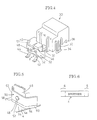
- Fig. 4 is an enlarged perspective view of a cutter holder;
- Fig. 5 is an enlarged perspective view of a cutter blade;
- Fig. 6 is a front view of a tape strip which has been severed by the tape cutter mechanism after printing;
- Fig. 7 is a schematic illustration explanatory of the cutter blade;
- Fig. 8 is an illustration explanatory of the tape strip severed by the cutter blade;
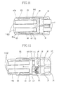
- Fig. 9 is a sectional view of the trimmer shown in full line position in Fig. 3;
- Fig. 10 is a sectional view of the trimmer shown in dotted line position in Fig. 3;
- Fig. 11 is a top view of an end shaping mechanism in an operable position;
- Fig. 12 is a top view of the end shaping mechanism in a retracted position;
- Fig. 13 is a transverse section of a cover portion;
- Fig. 14 is a schematic illustration explanatory of the condition of the cutter blade abutted against the tape;
- Fig. 15 is a sectional view taken on line 15-15 of Fig. 9;
- Fig. 16 is a bottom view of a cutter holder with an integrally molded structure;
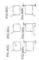
- Figs. 17(A) and 17(B) are sectional views of tape guides for different tape widths;
- Figs. 18(A) and 18(B) are schematic illustrations of tapes trimmed by the cutter blade in an embodiment of the invention;
- Figs. 19(A) and 19(B) are schematic illustrations of tapes trimmed by a cutter blade bent approximately at right angles;
- Figs. 20(A) and 20(B) are schematic illustrations of tapes trimmed by a cutter blade with wide angle cutting edges;
- Fig. 21 is a schematic illustration explanatory of a wavy contour which is imparted to the cutting edge in the cutter blade forming process;
- Fig. 22 is a sectional view explanatory of a half-cutting mechanism;
- Fig. 23 is a schematic illustration of a tape strip trimmed by a conventional semi-circular cutter blade; and
- Fig. 24 is a perspective view of a printing apparatus incorporating the cutter of the invention into the top surface of the housing of the printing apparatus.
- Hereafter, the invention is described particularly by way of the preferred embodiment shown in the drawings.
- Referring to Fig. 1, there is shown in a perspective view a printing apparatus embodying the present invention, which includes a
letter selector dial 8 rotatably mounted on atop surface 2a of ahousing 2 and having anannular dial surface 10 bearing thereon alphabetic letters, numeric figures, characters, symbols etc. to be entered. Provided side by side with theselector dial 8 are a group offunction keys 14 which control various functions of the printing,apparatus 1, including indicating an entered letter on aliquid crystal display 16 and printing same on atransparent tape 4. Referring to Fig. 2, the letter is printed by a thermaltype printing head 70 which thermally transfers ink from anink ribbon 71 onto thetape 4. In this printing operation, each character is printed as a laterally reversed image on thetransparent tape 4. Accordingly, each character can be viewed as a normal image from the other side 4a of thetransparent tape 4 away from the printed face 4b. As the printed portion of thetape 4 is fed past theprinting head 70, a double-faceadhesive tape 73 with a peelable tape on one side thereof is adhered on the printed face 4b of thetape 4 by a pair of presser rollers. Thetape 4,ink ribbon 71 and adhesive tape with a peelable backing tape on one side are wound into rolls and accommodated in a common cartridge (not shown) which is detachably mounted in theprinting apparatus 1. The printedtape 4 bonded with the double-face adhesive tape is discharged out of thehousing 2 through atape outlet 16. The dischargedtaple 4 is severed by a first cutter mechanism, namely, by acutting mechanism 18 which is provided with a cutter blade within a casing. The tape is cut off when it is fed to a position where its printed portion is directly visible to the operator. Accordingly, thetape 4 can be cut off with a blank tape portion of a predetermined length posterior to the printed portion. As a result, there is obtained a printed tape cut into a desired length, for example, a strip of printedtape 4 as shown in Fig. 6. The above-described arrangement of the printing apparatus is substantially same as the one which is disclosed in Laid-Open European Patent Application Publication No. 0 319 209. Similar apparatus is disclosed in U.S. Patent No. 4,927,278. Both documents are incorporated herein by reference. As mentioned hereinbefore, the printing apparatus further includes anend trimming mechanism 20 as a second cutter mechanism for trimming anend portion 6 of thetape 4 which has been cut off in the above-described manner. Theend trimming mechanism 20 is provided integrally on thetop side 3 of thehousing 2 of theprinting apparatus 1, so that the operator can readily trim the tape end whenever necessary. - Reference is had to Fig. 2 which shows the
first cutting mechanism 18. As seen in this figure, acutter shaft 72 is provided within thehousing 2 at a position downstream of theprinting head 70. Rotatably supported onshaft 72 is acutter member 74 which is operable to cut off a printed portion of thetape 4. Thecutter member 74 is constituted by astraight cutter blade 76 for severing thetape 4, and ablade holder 78 which holds thecutter blade 76. Theblade holder 78 is provided with a bore formed vertically therethrough for receiving thecutter shaft 72, and acutter gear portion 80 is formed on a circumferential side portion about the bore. Thecutter member 74 is rotated by acutter lever 82 which is rotatably mounted on alever shaft 84 which is provided within thehousing 2. Thecutter lever 82 is integrally provided with alever gear 86 which is formed about thelever shaft 84 for meshing engagement with thecutter gear 80. More specifically, thecutter gear 80 of thecutter member 74 and thelever gear 86 of thecutter lever 82 which meshes with thecutter gear 80 are meshed with each other through a plural number of teeth which are provided in a circumferential direction about the respective pivoting shafts to transfer rotational force in the circumferential direction without transfer of force therebetween in a direction perpendicular to the circumferential direction to permit mounting and extraction of thecutter member 74. Further, thecutter lever 82 is biased in a direction inverse to the direction of arrow A by aspring 88 to abut against a side wall of thehousing 2, so that thecutter blade 76 is normally retained in a position away from thetape 4. Ananvil 90 is located on the other side of thetape 4 away from thecutter blade 76. - The
tape 4 which is fed forward by a feeder mechanism, which is not shown, and led to a path between thecutter member 74 and theanvil 90. In this state, by rotating thecutter lever 82 in the direction of arrow A in Fig. 2, thecutter member 74 is rotated counterclockwise in Fig. 2 through thelever gear 86 andcutter gear 80. Whereupon, thetape 4 is pressed against theanvil 90 and severed by thecutter blade 76. - Turning now to the
trimming mechanism 20 for trimming anend 6 of the tape strip which has been printed and cut off in the above-described manner, such a mechanism is provided on oneside wall 3 of thehousing 2 as shown particularly in Fig. 3 such that part of thehousing 2 forms acasing 21 for thetrimming mechanism 20. In this particular embodiment, thetrimming mechanism 20 is provided with aguide groove 22 for a 12mm-wide tape and aguide groove 24 for a 16mm-wide tape side by side. The trimming cutter mechanisms for these tape widths are substantially the same in construction, except that the dimensions of tape guide portion and cutter blade are varied according to the tape width. Therefore, the trimming cutter mechanism is explained hereinafter by way of the mechanism for 12mm-wide tape. - The
guide groove 22 is formed by recessing theside wall 3 according to the width of thetape 4 in such a manner as to receive thetape strip 4 therein with the tape face 5 in a horizontal state. Theguide groove 22 is internally provided with a stopper surface 25 (Fig. 9) which delimits the depth of insertion of thetape 4 by abutting engagement therewith. - Provided within the
guide groove 22 is acutter holder 30 which is positioned astride the insertedtape 4, thecutter holder 30 being provided with locking portions 32 (only one of which is shown in Fig. 4) each with aanchor pawl 34 at the lower end thereof. Thecutter holder 30 is detachably and replaceably fixed on thecasing 21 through engagement of the anchor pawls 34 with thecasing 21. - The
cutter holder 30 is provided with atape guide portion 36 which prevents thetape 4 from flexing up upon insertion into theguide groove 22, ensuring that thetape 4 is inserted in an appropriate position along theguide groove 22. Thecutter holder 30 is further provided with a resilientlydeformable portion 38, which is extended toward thestopper surface 25 substantially in parallel relation with the insertedtape 4 and provided with ahollow cover portion 40 at the fore end thereof. Fig. 13 shows thecover portion 40 in a transverse sectional view. A pair ofpresser legs cover portion 40 toward the tape surface 4a thereby to press theend portion 6 of thetape 4 against theguide groove 22. - The
cover portion 40 is partly notched and interiorly formed with apendant holder portion 46 extending downwardly toward the tape surface 4a. Apin 48 which is inserted in theholder portion 46 is inserted into ahole 52 in acutter blade 50 to permit the latter to rock about thepin 48. Thepin 48 has a diameter which is smaller than that of thehole 52 in a predetermined degree. Thecutter blade 50 is engaged with thepin 48 so that it can rock back and forth and to the left and right as indicated by arrow F in Fig. 4. Accordingly, as shown in Figs. 5 and 14, thecutter blade 50 is uniformly and stably abutted against the tape surface 4a. In this connection, arib 51 which is formed on the inner side of thecover portion 40 is extended toward thecutter blade 50 to prevent its dislocation from thepin 48. - The
cutter blade 50 is provided with astraight cutting edge 54 which is extended across the width of thetape 4 as shown in Figs. 4 and 5. Arcuate cutting edges 56 and 58 with a radius R are formed contiguously on the opposite sides of thestraight cutting edge 54. Further, straightauxiliary cutting edges straight cutting edge 54. Although the angle ϑ is set at 120° in this particular embodiment, it should suitably fall in a range between 105° and 140°. In a case where the angle ϑ of the arcuate cutting edges 56 and 58 is as shown in Figs. 7 and 8, the corners of thetape 4 are trimmed into a round shape. Where the angle ϑ is increased beyond 120°, the rounding-off effect on the trimmed tape end corners becomes less perceivable in appearance. - Moreover, the
12mm tape 4 has a tolerance t of ± 0.5mm in width W. It follows that the minimum width L of thetape 4 is 11.5mm. To cope with the minimum width L, in this embodiment the afore-mentionedstraight cutting edge 54 and the two arcuate cutting edges 58 and 60 are formed in a width corresponding to the minimum width L. Namely, even when trimming a tape strip of the minimum width, at least the tape end corners are rounded off by the arcuate cutting edges 56 and 58. If thestraight cutting edge 54 and the arcuate cutting edges 56 and 58 are formed in a width smaller than the minimum width L, greater proportions of the tape are cut by the auxiliary cutting edges, which give an effect of straight cut rather than the rounding-off effect. Therefore, it would impair the smoothness of the rounding-off. - In this particular embodiment, the
cutter blade 50 is formed by arcuately bending a straight blade of SK material, of Shore hardness of about HS60, to form arcuate bends of radius R, namely, to form thestraight cutting edge 54, arcuate cutting edges 56 and 58, andauxiliary cutting edges - A
cutter holder 31 andcutter blade 51 of the same construction are also provided for trimming, for example, 9mm-wide tape strips. - Further, as shown in Figs. 3, 9 and 10, the
side wall 3 of thehousing 2 is recessed to form, as part of thecasing 21, abottom surface 61 extending parallel with theside wall 3 at a certain depth from the surface of theside wall 3, and opposedwalls side wall 3. As shown in Figs. 11 and 12, apositioning pin 65 and atransport rail 66 are projectingly provided on each of thesewalls bottom surface 61, and the positioning pins 65 are projected in a greater degree than the transport rails 66. - The
trimming cutter mechanism 20 further includes a lever holder orframe 75, which is provided withrail guide 68 in sliding engagement with the positioning pins 65 andtransport rails 66 for sliding movement in a direction parallel with thebottom surface 61. The rail guide is provided with slot-like stopper grooves 92 which are engaged with the distal end portions of the positioning pins 65. When thelever holder 75 is slid parallel with thebottom surface 61, it is abutted against the positioning pins 65 at the opposite ends of the stopper grooves 92 to delimit the range of its sliding movement between an operable position and a retracted position, as will be described hereinlater. - Further, the
lever holder 75 is provided with a plate-like locking arm 94 which is extended parallel with thebottom surface 61 and bent in the middle to form aprojection 95 of U-shape in section. The fore end of the lockingarm 94 is provided with aprojection 96 toward thebottom surface 61, while a pair of lockingridges arm 94 is formed of a resiliently deformable material, so that, if a force greater than a certain level is applied in a sliding direction, it can be moved in that direction, riding over the lockingridges - A
lever 102 is rockably supporting on a rockingshaft 101 which is provided on thelever holder 75, thelever 102 being pulled toward thebottom surface 61 and normally folded intolever holder 75 by atension spring 106 which is connected at one end to thelever 102 and at the other end to ahook portion 104 provided on thelever holder 75. When folded, thelever 102 is abutted against theprojection 95 to block further sliding movement toward thebottom surface 61. - The
lever holder 75 is slid in the forward direction or toward thecutter holder 30 to assume the operable position where its forward sliding movement is stopped by abutting engagement of the positioning pins 65 with ends of the stopper grooves 92, and thelever 102 is rocked in the direction of arrow D against the action of thetension spring 106 as shown in Fig. 10, pushing down theholder portion 40 of thecutter holder 30 to move thecutter blade 50 toward the tape surface 4a. Thelever holder 75 is slid in the rearward direction away from thecutter holder 30 to assume the retracted position where its rearward sliding movement is stopped by abutting engagement of the positioning pins 65 with the ends of the stopper grooves 92 as shown in Fig. 9, retracting thelever 102 from thecutter holder 30 so that thecutter holder 30 can be removed from theguide groove 22 from above. - The interior construction of the
tape guide 36 is now explained with reference to Fig. 15, which is a section taken on line 15-15 of Fig. 9 and to Fig. 16, which is a bottom view of thetape guide 36 integrally formed with thecutter holder 30. As shown in Fig. 15, thetape guide 36 is interiorly provided with a number ofparallel guide plates outermost guide plates 36a are abutted on thebottom surface 61 while the threecenter guide plates 36b are spaced from thebottom surface 61 by a gap which is slightly wider than the thickness of thetape 4. On thebottom surface 61,ribs 37 are formed.Ribs 37 are located outwardly of theoutermost guide plates 36a, substantially along the entire length of thetape guide 36. - In operation, for trimming an end of a
tape strip 4, the trimming cutter of this embodiment is used in the operable position shown in Fig. 10. Firstly, the operator inserts thetape strip 4 along theguide groove 22. At this time, sideward movements of thetape 4, which is being guided along theguide groove 22, are restricted by theguide plates 36a which are abutted against thebottom surface 61. Consequently, the center of thetape 4 is guided toward the center of thecutter blade 50. In the meantime, the threeguide plates 36b, which are spaced from thebottom surface 61 by a gap of a predetermined width, serve to prevent thetape 4 from flexingaway fromsurface 61. Further, the leaching end of thetape 4 is abutted against thestopper surface 25 which delimits the length of insertion of thetape 4. Therefore, thetape 4 is set in a centered position relative to thecutter blade 50 which is located at a predetermined distance from the leading end of thetape 4. In this operable position, the positioning pins 65 are abutted against the rear ends of the stopper grooves 92 to block further movement of thelever holder 90 toward thecutter holder 30. In addition, theprojection 96 of the lockingarm 94 is abutted against the lockingridge 98, to the side of thecutter holder 30, preventing thelever holder 90 from easily moving in a direction away from thecutter holder 30. As soon as thelever 102 is rocked by the operator in the direction of arrow D against the force of thetension spring 106, theholder portion 40 of thecutter holder 30 is pushed down by one end of thelever 102. Whereupon, thepresser legs end portion 6 of thetape strip 4 against theguide groove 22, and theresilient portion 38 is displaced downward through elastic deformation, moving the cutting edges 54, 56 and 58 of thecutter blade 50 toward the tape surface 5 for trimming thetape 4. - On the other hand, when the
tape 4,ink ribbon 71 and cartridge of the double-faceadhesive tape 73 are replaced for printing atape tape 4, thecutter holder 30 which is detachably fixed on thebottom surface 61 through the anchor pawls 34 is replaced by a cutter holder with atape guide tape guide 36, according to the width of thetape tape guide holder anchor pawls 34. In this case, thecutter blade 50 which is fixed on theholder portion 40 of thecutter holder 30 is replaced together with the latter. Accordingly, thecutter blade 50 is replaced by a blade of the size and shape conforming with the new tape. Thetape tape 4. - As shown in Fig. 17(A), the
tape guide 110 is shaped such thatguide plates 110a on the opposite sides of acenter guide plate 110b abutted against thebottom surface 61. Therefore, the cutter holder with such atape guide 110 needs a cutter blade having a cutting edge shorter than thecutter blade 50 in thecutter holder 30. In this cutter holder, sideward movement of thesmaller width tape 116 is restricted by theguide plates 110a. That is, the center of thetape 96 which is smaller in width than thetape 4, is guided toward the center position of the cutter blade and cut accurately in a desired shape by the cutter blade of suitable size and shape. - On the other hand, as shown in Fig. 17(B), the
tape guide 112 is shaped such that, when mounted on thetrimming mechanism 20, all of theguide plates 112a are spaced from thebottom surface 61 by a gap which is slightly greater than the thickness of the tape. Accordingly, the cutter holder with thetape guide 112 has a cutter blade with a cutting edge longer than theblade 50 on thecutter holder 30. In this cutter holder, sideward movement of the tape is restricted by theribs 128 provided on thebottom surface 61. Therefore, thetape 118, which is larger in width than thetape 4, is guided in centered relationship with the cutter blade and cut exactly in a desired shape by a cutter blade of a size and shape conforming with the tape width. - In the end trimming operation, the
straight cutting edge 54 of thecutter blade 50 cuts thetape 4 along a straight cut line in the transverse direction of the tape. Concurrently, the arcuate cutting edges 56 and 58 of thecutter blade 50 cut thetape 4 in an arcuate shape of the radius R contiguously to the straight cut line by thestraight cutting edge 54. Further, theauxiliary cutting edges tape 4 in a direction tangential to the arcs of the radius R and at an obtuse angle ϑ with the straight cut line of thestraight cutting edge 54. As a consequence, theend 6 of thetape 4 is trimmed into the shape as shown particularly in Fig. 9, with the two corner portions rounded off. Therefore, when thetape strip 4 is bonded on an article, it has less possibility of defoliating from the corners. In addition, the straight cut portion which is formed by thestraight cutting edge 54 can be conveniently used when it becomes necessary to bond the tape strip accurately flush with an edge of an article. - Further, there are irregularities in the tape width W, which may be a little broader or narrower than a specified width, while the
guide grooves guide grooves guide groove 22, thetape 4 might be slightly deviated to one side of theguide groove 22. Even in such a case, the two corner portions of the tape are cut in different degrees but they are at least cut in arcuate shapes by the arcuate cutting edges 56 and 58 in the present embodiment as shown in Fig. 18(B). Namely, the two corners are cut by the arcuate cutting edges 56 and 58 andauxiliary cutting edges - On the other hand, in a case where the angles ϑ formed by the
straight cutting edge 54 and theauxiliary cutting edges cutter blade 50 without positional deviations. However, if the center of thetape 4 is deviated from the center of thecutter blade 50 due to an irregularity in tape width W, one corner of the tape end is cut off in a greater degree by theauxiliary cutting edge tape 4 is trimmed in a shape which has an unbalanced look, impairing the appearance of the tape. - In a case where the angle ϑ of each of the
auxiliary cutting edges tape 4 is set in the centered position relative to thecutter blade 50 without positional deviations. However, in this case the effect of rounding-off is barely perceivable from the trimmed corners of thetape 4. Besides, if thetape 4 is trimmed in a deviated position relative to the center of thecutter blade 50, the arc at one corner of the tape becomes extremely small as shown in Fig. 20(B), and the trimmed tape end has an unbalanced look. - When the
cutter blade 50 is formed by a process as described hereinbefore, the edge portions of the blade may have a wavy contour as seen in Fig. 21 which shows the edge portions of the blade on an enlarged scale. Such wavy contour of the cutting edges can be utilized to effect the so-called half-cutting in which thetape 4 is partly left uncut instead of being completely severed. By this half-cutting, a cut is made only into the overlaidtape 4 and theadhesive tape 73 which is bonded to the printed face 4b of thetape 4, leaving uncut the peelable backing tape on the other side of theadhesive tape 73. This makes it very easy to remove the peelable backing tape from thetape 4 to which theadhesive tape 73 is bonded, providing a great convenience for the operator. - As a half-cutting mechanism, for example, there may be employed an arrangement as shown in Figs. 21 and 22, cutting the
tape 4 between thecutter blade 50 and ametal plate 132 of stainless steel which is embedded in thecasing 21 within theguide groove 22 through an adhesive 134 in face to face relation with thecutter blade 50. With this arrangement, themetal plate 132 is pushed down by flexure of theadhesive layer 134 or casing 21 which is caused at the time of the tape trimming operation by the pressure of thecutter blade 50 which is driven downward toward themetal plate 132. Thecutter blade 50 is uniformly abutted against themetal plate 132 but leaves part of thetape 4 uncut because of the wavy contour of the cutting edge, thus effecting the half-cutting. - It will be appreciated from the foregoing description that, when necessary, the printing apparatus according to the present invention permits trimming the
end 6 of a printedtape strip 4 into a desired shape by an extremely simple operation. Theend trimming cutter 20 might get lost if provided separately from the printing apparatus. However, theend trimming cutter 20 which is provided integrally on the side wall of thehousing 2 of theprinting apparatus 1 is completely free from such a problem. - At the time of replacement of the
cutter blade 50, thelever holder 75 in the operable position is pulled in the direction of arrow B away from thecutter holder 30, whereupon theprojection 96 rides over the lockingridge 98 on the side of thecutter holder 30 to permit therail guide 68 to move in the direction of arrow B in sliding contact with the positioning pins 65 and transport rails 66. The lockingarm 94 is then flexed to let theprojection 96 ride over theother locking ridge 100 until the positioning pins 65 come into abutting engagement against the ends of the stopper grooves 92 to assume the retracted position, blocking further movement of theguide rail 68 in the direction of arrow B. In this retracted position, thelever holder 75 will not slide in the direction of arrow B or toward thecutter holder 30 unless a force is applied thereto to such a degree as to flex the lockingarm 94, letting theprojection 96 ride over the lockingridge 100. - After shifting the
lever 102 and thelever holder 75 from the operable position to the retracted position in this manner, the lockingpawls 34 of thecutter holder 30, which are interlocked with thecasing 21 are detached therefrom and thecutter blade 50 is removed out of theguide groove 22 along with thecutter holder 30 in the direction indicated by arrow C (Fig. 9). Then, afresh cutter holder 30 is fixedly set in the predetermined position by interlocking itsanchor pawls 34 with thecasing 21, and thelever holder 75 is pushed in the opposite direction of arrow B. Whereupon, the lockingarm 94 is flexed to let theprojection 96 ride over the lockingridge 100 and then the other lockingridge 98. This sliding movement is stopped as soon as the positioning pins 65 come into abutting engagement against the rear ends of the stopper grooves 92, setting thelever holder 75 in the operable position. - When trimming the
tape 4 in the above-described manner, thelever 102 in the operable position causes thecutter blade holder 40 to move toward the tape surfaces. On the other hand, in order to replace thecutter blade 50, thelever 102 is shifted from the operable position to the retracted position together with thelever holder 75, and then thecutter blade 50 is detached from thecasing 21 for replacement together with thecutter holder 30. Therefore, there is no possibility of thelever 102 interfering with replacement of the cutting blade. Besides, even in a case where thehousing 2 is arranged to form part of thecasing 21 of thetrimming cutter 20 as in the present embodiment, thecutter blade 50 can be easily removed in the direction of arrow C for replacement. Since the cutter blade is integrally assembled with the tape guide through the cutter holder, a tape guide conforming with the size of a replacment cutter blade is simultaneously provided at the time of replacement of the cutter blade. Therefore, the tape to be trimmed by a fresh cutter blade is securely urged into the centered position by the fresh tape guide, thereby ensuring trimming of the tape end securely in a desired shape. It follows that theend 6 of thetape strip 4 can be trimmed in any desired shape by selectively using a suitable one of cutter blades of diverse shapes. - Although the
trimming cutter mechanism 20 of the present embodiment is provided with a pair ofguide grooves - The
ribs 37 which are provided on thebottom surface 61 in the foregoing embodiment may be omitted in a case where the inner wall surfaces are used as guide plates. - Furthermore, as the
lever holder 75 and other associated components are received in theguide groove 22 as shown in Fig. 3, thetrimming cutter 20 can be provided not only on theside wall 3 but also on the top or other side walls of theprinting apparatus 1 as long as there is a space corresponding to the size of theguide groove 22. For example, onetrimming cutter mechanism 144 may be provided on thetop surface 142 of a housing of aprinting apparatus 140 as shown in Fig. 24. It follows that thetrimming cutter 20 can be incorporated into theprinting apparatus 1 without any restrictions with regard to its location. - It is to be understood that the present invention is not restricted to the particular forms shown in the foregoing embodiment, and various modifications and alterations can be added thereto without departing from the scope of the invention as encompassed by the appended claims.
Claims (24)
- A tape cutting apparatus comprising;
a tape support member for supporting a tape strip thereon,
a cutter member having a cutting edge for cutting the tape,
a cutter support member for supporting the cutter member. - A tape cutting apparatus according to claim 1 wherein;
the support member supports the cutter member for movement in a tape cutting direction. - A tape cutting apparatus according to claim 1 or 2 wherein;
the cutting edge corresponds to the width of the tape strip. - A tape cutting apparatus according to claim 2 or 3 wherein;
the cutting edge is movable toward the tape support member to cut the tape strip; and comprising
a restricting member provided integrally with the cutter support member for restricting sideward movement of the tape on the tape support member; and
a locking member adapted to replaceably mount the cutter support member and the restricting member on the tape support member. - A tape cutting apparatus as in claim 4, wherein the restricting member comprises at least one wall extending from the cutter support member to said tape support member.
- A tape cutting apparatus as in claim 4 or 5, wherein the restricting member comprises a pair of parallel walls extending from the cutter support member to said tape support member.
- A tape cutting apparatus as in claim 4, 5 or 6, wherein the tape support member includes means spaced outwardly of the restricting member for restricting sideward movement of tape on the tape support member.
- A tape cutting apparatus according to claim 2 or 3 wherein the cutter support member comprises;
a cutter member receiving means for holding the cutter member;
means mounting the cutter member receiving means and for movement toward the support member; and
means carried by the cutter member receiving means for pressing the tape against the tape support member as the tape is cut by the cutter member. - A tape cutting apparatus as in claim 8, wherein the tape pressing means comprises an elongate flexible member mounted on the cutter member receiving means.
- A tape cutting apparatus as in claim 8, wherein the tape pressing means comprises a pair of spaced, elongate, flexible members mounted on the cutter member receiving means.
- A tape cutting apparatus according to claim 2 or 3 comprising;
a cutter member receiving means on the cutter member support for receiving the cutter member;
means mounting the cutter member receiving means for movement toward and away from the tape support member;
and
means for mounting the cutter member on the receiving means to provide rocking movement of the cutter member with respect to the tape support member. - A tape cutting apparatus as in claim 11, wherein the means for mounting the cutter member on the cutter member receiving means comprises a pin, and wherein the cutter member is loosely received on the pin.
- A tape cutting apparatus as in claim 12, further comprising means carried by the cutter member receiving means for maintaining the cutter member on the pin.
- A tape cutter according to claim 1 wherein the cutter support member comprises a body; and comprising
means for replaceably mounting the body on the tape support member surface;
guide means mounted on the body for defining a longitudinal pathway for guiding sideways movement of a tape said pathway having a transverse dimension; and
wherein said cutting member comprises a cutting blade mounted in the body in a position transverse to the said longitudinal pathway, said cutting blade having a straight cutting edge; two arcuate cutting edges one of the arcuate cutting edges being contiguous with one end of the straight cutting edge and the other arcuate cutting edge being contiguous with the other end of the straight cutting edge; the transverse extend of the straight cutting blade and the two arcuate cutting edges being less than the transverse dimension of said pathway. - A tape cutter as in claim 14, wherein the means defining said longitudinal pathway comprises a pair of spaced, parallel guides.
- A tape cutter as in claim 14, wherein the body comprises
a guide part;
a blade receiving part; and
means mounting the blade receiving part for movement with respect to the guide part. - A tape cutting apparatus as in any preceding claim, further comprising means on the cutter support member for limiting movement of the tape away from the tape support member.
- A tape cutting apparatus as in claim 17, wherein the means for limiting movement of the tape away from the tape support member comprises at least one elongate member extending along and spaced from the tape support member.
- A tape cutting apparatus as in any preceding claim, wherein the cutter support member includes a blade receiving means for receiving the cutter member and support means for mounting the receiving means for movement toward and away from the tape support member.
- A tape cutting apparatus as in claim 19, wherein the support means comprises a flexible, elastic member supporting the blade receiving means.
- A tape cutting apparatus as in claim 19 or 20, wherein the blade receiving means and the support means are integrally molded portions of the cutter support member.
- A tape cutting apparatus as in any preceding claim, wherein the cutter support member further comprises means for pressing the tape against the tape support member as the tape is being cut by the cutter member.
- A tape cutting apparatus as in any preceding claim, wherein the cutter member comprises:
a straight cutting edge;
a pair of arcuate cutting edges, one of the arcuate cutting edges being contiguous with one end of the straight cutting edge and the other of the arcuate cutting edges being contiguous with the other end of the straight cutting edge; and
a pair of auxiliary straight cutting edges, one of the auxiliary cutting edges being contiguous with the other of the arcuate cutting edges, said auxiliary straight cutting edges each being disposed at an obtuse angle with respect to the straight cutting edge. - A tape cutting apparatus as in any preceding claim, wherein the cutter member is rockable in lateral and longitudinal directions.
Applications Claiming Priority (6)
| Application Number | Priority Date | Filing Date | Title |
|---|---|---|---|
| JP90021/90 | 1990-04-04 | ||
| JP9002190A JPH03287397A (en) | 1990-04-04 | 1990-04-04 | Tape cutting device |
| JP12606290A JPH0425398A (en) | 1990-05-15 | 1990-05-15 | Tape cutting device |
| JP126062/90 | 1990-05-15 | ||
| JP151399/90 | 1990-06-08 | ||
| JP15139990A JP2921042B2 (en) | 1990-06-08 | 1990-06-08 | Tape cutting device |
Publications (2)
| Publication Number | Publication Date |
|---|---|
| EP0450779A1 true EP0450779A1 (en) | 1991-10-09 |
| EP0450779B1 EP0450779B1 (en) | 1995-06-21 |
Family
ID=27306327
Family Applications (1)
| Application Number | Title | Priority Date | Filing Date |
|---|---|---|---|
| EP19910302198 Expired - Lifetime EP0450779B1 (en) | 1990-04-04 | 1991-03-14 | Tape cutting apparatus |
Country Status (3)
| Country | Link |
|---|---|
| US (1) | US5163349A (en) |
| EP (1) | EP0450779B1 (en) |
| DE (1) | DE69110520T2 (en) |
Cited By (2)
| Publication number | Priority date | Publication date | Assignee | Title |
|---|---|---|---|---|
| EP0644055A2 (en) * | 1993-09-22 | 1995-03-22 | Brother Kogyo Kabushiki Kaisha | Print tape forming apparatus having tape cutting mechanism |
| EP1498229A2 (en) * | 2003-07-16 | 2005-01-19 | tesa AG | Method of cutting a web having at least an adhesive side laying on a protective substrate into individual finished elements |
Families Citing this family (7)
| Publication number | Priority date | Publication date | Assignee | Title |
|---|---|---|---|---|
| US5584962A (en) | 1994-05-20 | 1996-12-17 | Bradshaw; Franklin C. | Laminating and adhesive transfer apparatus |
| US5788796A (en) * | 1994-05-20 | 1998-08-04 | Minnesota Mining And Manufacturing | Decal assembly and method of making same |
| AU1372899A (en) | 1997-11-07 | 1999-05-31 | Xyron, Inc. | Laminating and adhesive transfer apparatus with an exit tray |
| US6698487B2 (en) * | 2000-11-15 | 2004-03-02 | Xyron, Inc. | Master processing apparatus |
| US7616924B2 (en) * | 2004-07-16 | 2009-11-10 | Konica Minolta Business Technologies, Inc. | Sheet post-processing and image forming system with a sheet-trimming apparatus containing a blade and blade-receiving member driving mechanisms |
| US20060260740A1 (en) * | 2005-05-18 | 2006-11-23 | Innodesk, Inc | Home and Office, Cold Seal, Manual, Thermal Trimmed Continuous Adhesive Web Laminating Device |
| JP2018161843A (en) * | 2017-03-27 | 2018-10-18 | カシオ計算機株式会社 | Printer and printing method |
Citations (3)
| Publication number | Priority date | Publication date | Assignee | Title |
|---|---|---|---|---|
| US3854361A (en) * | 1971-06-15 | 1974-12-17 | Xerox Corp | Quick change labeling head |
| DE2438001A1 (en) * | 1973-08-14 | 1975-02-27 | Bruno Giovannini | DEVICE FOR SEPARATING CONTINUOUS FORMS |
| EP0319209A2 (en) * | 1987-11-28 | 1989-06-07 | Brother Kogyo Kabushiki Kaisha | Recording apparatus with mechanism for cutting printed tape covered by backing tape |
Family Cites Families (11)
| Publication number | Priority date | Publication date | Assignee | Title |
|---|---|---|---|---|
| US2582979A (en) * | 1948-07-24 | 1952-01-22 | Harold G Kendall | Device for using tape |
| US2921493A (en) * | 1956-12-03 | 1960-01-19 | Fed Tool Corp | Tape dispenser |
| US3310145A (en) * | 1964-02-19 | 1967-03-21 | Dymo Industries Inc | Cutoff means for hand operated embossing tool |
| US3370497A (en) * | 1966-03-08 | 1968-02-27 | Clarence E. Busse | Cutting means for dispenser of sheet material |
| US3366212A (en) * | 1966-05-16 | 1968-01-30 | Apsco Products Inc | Embossing tool capable of using different width tapes |
| US3918338A (en) * | 1973-10-03 | 1975-11-11 | James H Higbee | Gummed tape dispenser |
| US3971280A (en) * | 1975-11-06 | 1976-07-27 | Crane Packing Company | Tape dispenser |
| US4227305A (en) * | 1979-03-12 | 1980-10-14 | Newman Jerry C | Hand tool for cutting blind strips and the like |
| US4488466A (en) * | 1982-09-07 | 1984-12-18 | Seal Tech Corp. | Apparatus for cutting sheet material |
| JP2516990B2 (en) * | 1987-07-17 | 1996-07-24 | 松下電器産業株式会社 | Optical disc player |
| US4927278A (en) * | 1987-12-29 | 1990-05-22 | Brother Kogyo Kabushiki Kaisha | Tape cassette and tape printer for use therewith |
-
1991
- 1991-02-11 US US07/653,267 patent/US5163349A/en not_active Expired - Fee Related
- 1991-03-14 DE DE1991610520 patent/DE69110520T2/en not_active Expired - Fee Related
- 1991-03-14 EP EP19910302198 patent/EP0450779B1/en not_active Expired - Lifetime
Patent Citations (3)
| Publication number | Priority date | Publication date | Assignee | Title |
|---|---|---|---|---|
| US3854361A (en) * | 1971-06-15 | 1974-12-17 | Xerox Corp | Quick change labeling head |
| DE2438001A1 (en) * | 1973-08-14 | 1975-02-27 | Bruno Giovannini | DEVICE FOR SEPARATING CONTINUOUS FORMS |
| EP0319209A2 (en) * | 1987-11-28 | 1989-06-07 | Brother Kogyo Kabushiki Kaisha | Recording apparatus with mechanism for cutting printed tape covered by backing tape |
Cited By (4)
| Publication number | Priority date | Publication date | Assignee | Title |
|---|---|---|---|---|
| EP0644055A2 (en) * | 1993-09-22 | 1995-03-22 | Brother Kogyo Kabushiki Kaisha | Print tape forming apparatus having tape cutting mechanism |
| EP0644055A3 (en) * | 1993-09-22 | 1996-02-07 | Brother Ind Ltd | Print tape forming apparatus having tape cutting mechanism. |
| EP1498229A2 (en) * | 2003-07-16 | 2005-01-19 | tesa AG | Method of cutting a web having at least an adhesive side laying on a protective substrate into individual finished elements |
| EP1498229A3 (en) * | 2003-07-16 | 2005-07-06 | tesa AG | Method of cutting a web having at least an adhesive side laying on a protective substrate into individual finished elements |
Also Published As
| Publication number | Publication date |
|---|---|
| DE69110520D1 (en) | 1995-07-27 |
| DE69110520T2 (en) | 1996-02-01 |
| US5163349A (en) | 1992-11-17 |
| EP0450779B1 (en) | 1995-06-21 |
Similar Documents
| Publication | Publication Date | Title |
|---|---|---|
| EP0611722B1 (en) | Tape cutting apparatus | |
| US5224786A (en) | Tape printer with end trimming cutter | |
| EP0634275B1 (en) | A cassette for a thermal printer | |
| EP0449465B1 (en) | Tape printer with end trimming cutter | |
| US5937725A (en) | Laminated sheet cutting method | |
| US7354210B2 (en) | Label printer | |
| EP2174792B1 (en) | Cutting mechanism for printing apparatus, and printing apparatus including the same | |
| EP2052820B1 (en) | Printing apparatus | |
| US5271789A (en) | Tape end processing unit | |
| US7108257B2 (en) | Sheet-supply device | |
| EP0450779B1 (en) | Tape cutting apparatus | |
| JP4273194B2 (en) | Printing device with a long printing medium cutting device | |
| KR101759404B1 (en) | Printing paper cutting device and printing device | |
| KR100422086B1 (en) | Tape end trimming apparatus | |
| CN111976316B (en) | Half cutter and tape printing apparatus | |
| JP2009160663A (en) | Cutter | |
| JPH0752479A (en) | Printer, cassette for printer, and blade protective device | |
| JP7361432B1 (en) | Holder for circular blades | |
| JP6960678B2 (en) | Sheet cutting device | |
| JP7462367B2 (en) | Cutting Mechanism | |
| EP0326336A2 (en) | Overhead type file sheet projectors, and file sheets and jacket holders for use in such projectors | |
| JP6704152B2 (en) | Printer | |
| KR101739662B1 (en) | Printing paper cutting device and printing device | |
| KR101739661B1 (en) | Printing paper cutting device and printing device | |
| CN111976317A (en) | Half cutter and tape printing apparatus |
Legal Events
| Date | Code | Title | Description |
|---|---|---|---|
| PUAI | Public reference made under article 153(3) epc to a published international application that has entered the european phase |
Free format text: ORIGINAL CODE: 0009012 |
|
| AK | Designated contracting states |
Kind code of ref document: A1 Designated state(s): BE DE FR GB |
|
| 17P | Request for examination filed |
Effective date: 19911121 |
|
| 17Q | First examination report despatched |
Effective date: 19930708 |
|
| GRAA | (expected) grant |
Free format text: ORIGINAL CODE: 0009210 |
|
| AK | Designated contracting states |
Kind code of ref document: B1 Designated state(s): BE DE FR GB |
|
| REF | Corresponds to: |
Ref document number: 69110520 Country of ref document: DE Date of ref document: 19950727 |
|
| ET | Fr: translation filed | ||
| PLBE | No opposition filed within time limit |
Free format text: ORIGINAL CODE: 0009261 |
|
| STAA | Information on the status of an ep patent application or granted ep patent |
Free format text: STATUS: NO OPPOSITION FILED WITHIN TIME LIMIT |
|
| 26N | No opposition filed | ||
| PGFP | Annual fee paid to national office [announced via postgrant information from national office to epo] |
Ref country code: GB Payment date: 19980305 Year of fee payment: 8 |
|
| PGFP | Annual fee paid to national office [announced via postgrant information from national office to epo] |
Ref country code: FR Payment date: 19980310 Year of fee payment: 8 |
|
| PGFP | Annual fee paid to national office [announced via postgrant information from national office to epo] |
Ref country code: DE Payment date: 19980320 Year of fee payment: 8 |
|
| PGFP | Annual fee paid to national office [announced via postgrant information from national office to epo] |
Ref country code: BE Payment date: 19980518 Year of fee payment: 8 |
|
| PG25 | Lapsed in a contracting state [announced via postgrant information from national office to epo] |
Ref country code: GB Free format text: LAPSE BECAUSE OF NON-PAYMENT OF DUE FEES Effective date: 19990314 |
|
| PG25 | Lapsed in a contracting state [announced via postgrant information from national office to epo] |
Ref country code: BE Free format text: LAPSE BECAUSE OF NON-PAYMENT OF DUE FEES Effective date: 19990331 |
|
| BERE | Be: lapsed |
Owner name: BROTHER KOGYO K.K. Effective date: 19990331 |
|
| GBPC | Gb: european patent ceased through non-payment of renewal fee |
Effective date: 19990314 |
|
| PG25 | Lapsed in a contracting state [announced via postgrant information from national office to epo] |
Ref country code: FR Free format text: LAPSE BECAUSE OF NON-PAYMENT OF DUE FEES Effective date: 19991130 |
|
| REG | Reference to a national code |
Ref country code: FR Ref legal event code: ST |
|
| PG25 | Lapsed in a contracting state [announced via postgrant information from national office to epo] |
Ref country code: DE Free format text: LAPSE BECAUSE OF NON-PAYMENT OF DUE FEES Effective date: 20000101 |