EP0450186B1 - Medication infusion device with dose recharge restriction - Google Patents
Medication infusion device with dose recharge restriction Download PDFInfo
- Publication number
- EP0450186B1 EP0450186B1 EP90125189A EP90125189A EP0450186B1 EP 0450186 B1 EP0450186 B1 EP 0450186B1 EP 90125189 A EP90125189 A EP 90125189A EP 90125189 A EP90125189 A EP 90125189A EP 0450186 B1 EP0450186 B1 EP 0450186B1
- Authority
- EP
- European Patent Office
- Prior art keywords
- medication
- valve
- pump
- septum
- fluid
- Prior art date
- Legal status (The legal status is an assumption and is not a legal conclusion. Google has not performed a legal analysis and makes no representation as to the accuracy of the status listed.)
- Expired - Lifetime
Links
Images
Classifications
-
- A—HUMAN NECESSITIES
- A61—MEDICAL OR VETERINARY SCIENCE; HYGIENE
- A61M—DEVICES FOR INTRODUCING MEDIA INTO, OR ONTO, THE BODY; DEVICES FOR TRANSDUCING BODY MEDIA OR FOR TAKING MEDIA FROM THE BODY; DEVICES FOR PRODUCING OR ENDING SLEEP OR STUPOR
- A61M5/00—Devices for bringing media into the body in a subcutaneous, intra-vascular or intramuscular way; Accessories therefor, e.g. filling or cleaning devices, arm-rests
- A61M5/14—Infusion devices, e.g. infusing by gravity; Blood infusion; Accessories therefor
- A61M5/142—Pressure infusion, e.g. using pumps
- A61M5/14244—Pressure infusion, e.g. using pumps adapted to be carried by the patient, e.g. portable on the body
- A61M5/14276—Pressure infusion, e.g. using pumps adapted to be carried by the patient, e.g. portable on the body specially adapted for implantation
- A61M5/1428—Pressure infusion, e.g. using pumps adapted to be carried by the patient, e.g. portable on the body specially adapted for implantation with manual pumping action
Definitions
- This invention relates generally to infusion systems for the administration of medications. More particularly, the present invention relates to a refillable and subcutaneously implantable medication delivery system including means for limiting the total amount of medication which can be infused therethrough over a given period of time.
- a typical drawback of out-patient treatment programs includes the requirement of frequent visits by the patient with the physician and the resultant time and transportation problems. It is recognized that if the patient could be provided adequate home care for extended periods of time, the time between visits with the physician could be lengthened. Such extended home care would benefit the physician, as well as the patient in many circumstances, by permitting the physician to devote more professional time to other important matters.
- an infusion system which allows the patient to administer required medications in precise quantities while minimizing the number of injections required and visits which need be made with a physician.
- Such an infusion system is needed which inherently limits the amount of medication which can be infused into the patient over a given period of time.
- such limitation on the total amount of medication which can be infused over a given period of time can be accomplished independently of the size of a reservoir for storing the medication.
- a novel medication delivery device which may be totally subcutaneously emplaced in the body, includes appropriate devices to prevent the unintended infusion of the medication from the system to the body, is refillable by injection to permit long-term use, and includes an inherent recharge restriction capability for limiting the rate at which medication may be infused to the body while preserving the ability of the patient to self-administer the medication on demand in a safe and reliable manner.
- a novel process is needed for percutaneously controlling the flow of fluid through a subcutaneously implanted infusion system including a manually actuable pump and a valve for controlling the flow of fluid from the pump. The present invention fulfills these needs and provides other related advantages.
- the present invention resides in a medication infusion device useful, for example, in the administration of medication to patient requiring infusions of medication at relatively frequent intervals and over extended periods of time. More particularly, the present invention resides in a medication infusion system which is totally subcutaneously implanted in the patient, and is manually actuated by the application of percutaneous pressure to infuse a measured bolus of medication on demand.
- the infusion system comprises, generally, means for receiving medication into the system by injection, a reservoir fluidly connected to the receiving means in a manner permitting the subcutaneous transfer of medication from the receiving means to the reservoir, and a delivery catheter for directing the medication to a specific location in the body. Means are provided for conducting the medication from the reservoir to the catheter inlet.
- Means are also provided for controlling the flow of medication from the reservoir to the catheter, forming a portion of the conducting means, which include a normally closed valve and a pump for flushing a measured quantity of medication into the catheter when the normally closed valve is opened.
- the valve means and the pump are actuated by manual percutaneous manipulation thereof.
- the invention is characterized in that means are provided for restricting the flow of medication from the reservoir to the pump, and thus limiting the rate the pump is recharged, to restrict the total amount of medication which can be pumped into the catheter over a given period of time.
- the restricting means is positioned within the normally closed valve means and includes a fluid pathway through which medication must pass before entering the pump, wherein manipulation of the valve means to open it occludes the fluid pathway to close a portion of the conducting means defined by the restricting means.
- the controlling means comprises a subcutaneously implantable medication infusion control assembly having a medicament recharge restriction.
- the control assembly includes a self-recharging, manually actuable pump for discharging a measured amount of fluid from a pumping chamber.
- the pump includes a pump inlet in fluid communication with the reservoir, a pump outlet in fluid communication with the normally closed valve, and a resilient crown overlying a floor plate to define the pumping chamber therebetween.
- Means are provided for conducting pump recharge fluid from the receiving means and the reservoir into the pumping chamber, and means are provided for conducting discharge fluids from the pumping chamber to the catheter.
- the control assembly also includes a normally closed valve which is actuable by manual percutaneous manipulation for controlling the flow of discharge fluid from the pumping chamber.
- the normally closed valve forms a portion of the discharge fluid conducting means and includes a resiliently flexible body which defines a fluid flow passageway therethrough.
- a valve member is positioned within the fluid flow passageway to occlude the valve.
- the normally closed valve further includes a valve inlet in fluid communication with the pump outlet, a valve outlet in fluid communication with the catheter inlet, and a valve passageway situated directly between the valve inlet and outlet.
- the valve member is resiliently biased to occlude the valve passageway, and a displacement finger is situated and configured within the valve to displace the valve member and open the valve to fluid flow therethrough when actuated by manual percutaneous pressure.
- the control assembly is further provided with means for restricting the rate of fluid flow through the recharge fluid conducting means.
- the restricting means effectively limits the amount of recharge fluid permitted to enter the pumping chamber over a given period of time.
- the restricting means includes at least one capillary-like fluid pathway through which the recharge fluid must pass before entering the pumping chamber.
- the restricting means is positioned relative to the displacement finger so that manipulation of the normally closed valve to move the displacement finger, which opens the discharge fluid conduit means, occludes the capillary-like fluid pathway restrictor to occlude the recharge fluid conducting means.
- the restricting means includes a wick restrictor having a plurality of wicking fibers situated within an impermeable wick housing.
- the wick restrictor is positioned within a portion of the recharge fluid conducting means so that all fluid drawn into the pumping chamber must first pass through the wick restrictor.
- One end of the wick housing is occluded, and an inlet is provided adjacent to the occluded end through a wall of the wick housing.
- the means for receiving medication into the system by injection comprises an injection port including, generally, an elastomeric outer housing having an integral elastomeric septum, a pair of base members situated within the outer housing and which compress a portion of the septum therebetween, and an outlet.
- the outlet extends from an internal chamber between the septum and the base members, exteriorly through the outer housing.
- Another aspect of the present invention involves a novel process for infusing medication stored within a subcutaneously implanted infusion system.
- a process for percutaneously controlling the flow of fluid through a subcutaneously implanted infusion system including a manually actuable pump having a pump inlet and a pump outlet, and a valve for controlling the flow of fluid from the pump, comprises a number of novel process steps.
- the valve is opened by applying percutaneous pressure thereto, to permit medication in the pump to be discharged through the pump outlet.
- the step of opening the valve includes pressing a housing of the valve downwardly.
- the pump inlet is occluded to prevent medication from entering the pump when the valve is opened.
- the steps of opening the valve and occluding the pump inlet are accomplished simultaneously through the application of the percutaneous pressure to the valve.
- Medication in the pump is discharged through the pump outlet and the valve by applying percutaneous pressure to the pump. This is accomplished by pressing a housing of the pump downwardly to flush fluid from a pump chamber within the pump, wherein the step of flushing fluid from the pump occurs only after the valve is opened.
- valve After the medication has been discharged from the pump, the valve is closed by removing the percutaneous pressure applied thereto, and the pump inlet is opened to permit fluid flow into the pump when the valve is closed.
- the steps of closing the valve and opening the pump inlet are accomplished simultaneously through the withdrawal of percutaneous pressure from the valve.
- the rate at which fluid can flow into the pump through the pump inlet is restricted in order to limit the amount of fluid which can be pumped through the infusion system over a given time period.
- fluid stored in the infusion system is caused to pass through a capillary-like fluid pathway as the fluid is drawn into the pump.
- the capillary-like fluid pathway severely restricts the rate at which fluid would otherwise flow into the pump, to a known flow rate that limits the maximum amount of fluid which can be pumped through the system over a given time period.
- the capillary-like fluid pathway is closed to fluid flow when percutaneous pressure is applied to the valve.
- fluid stored in the infusion system is caused to pass through a plurality of packed wicking fibers.
- the wicking fibers are placed in a fluid flow conduit between the pump and the stored medication, and the medication is introduced at the wicking fibers perpendicularly to their length.
- the present invention is concerned with an improved medication infusion system, generally designated in the accompanying drawings by the reference number 20.
- the medication infusion system 20 generally comprises a variable capacity reservoir 22 connected by a fluid flow conduit 24 to a catheter 26 which directs medications stored in the reservoir to a specific location within a patient.
- a fluid flow control assembly 28 is provided to prevent or reduce the likelihood of an inadvertent infusion into the patient of medication stored in the reservoir 22.
- the control assembly 28 used in the system 20 is situated between the reservoir 22 and the catheter 26 to form a portion of the fluid flow conduit 24.
- the system 20 requires fluid medication to flow through the control assembly 28 before passing into the catheter 26. With the safety and well-being of the patient and all-important consideration in the employment of the system 20, this flow path requirement provides the control over the flow of medication which is critical to the system's safe use. Indeed, the control assembly 28 virtually eliminates the chance of inadvertently infusing more than a very small quantity of medication into the patient by requiring specific sequential and deliberate steps to be taken before a measured volume of fluid can be pumped through the system 20.
- the medication infusion system 20 can substantially reduce the cost of treating some illnesses by eliminating the need for constant medical attention or by reducing the number of required visits which need be made with a physician.
- the overall design of the system 20 permits construction into a variety of configurations for use in many types of different applications.
- the system 20 may be used advantageously by patients requiring regular infusions by minimizing the number of injections received.
- the medication infusion system 20 of the present invention includes means for limiting the maximum amount of medication which can be pumped through the system over a given time period.
- variable capacity reservoir 22 comprises a silicone elastomer shell 30 which can expand and collapse to accommodate changing volumes of fluid medication.
- the reservoir 22 includes an outlet aperture 32 and an outlet connector 34 secured within the aperture 32.
- the outlet connector 34 is designed to engage one end of a first segment of surgical tubing 36 which extends between the reservoir 30 and the control assembly 28.
- a flexible tube 38 having a plurality of tube apertures 40 extends from the reservoir aperture 32 generally rearwardly into the center of the reservoir 22.
- the flexible tube 38 is preferably constructed of a silicone elastomer material having sufficient resiliency to maintain a fluid passageway through its center for channeling fluid medication from the reservoir 22 through the aperture 32 and into the first segment of surgical tubing 36, notwithstanding a collapse of the reservoir shell 30.
- the flexible tube 38 ensures that fluid medication will be able to exit the reservoir 22 even when the reservoir shell 30 collapses in a manner that would otherwise cover the reservoir outlet aperture 32. Such a collapse of the reservoir shell 30 may result from an emptying of fluid from the reservoir 22 during use of the system 20.
- variable capacity reservoir 22 In systems 20 designed for use in the treatment of terminally ill patients, a reservoir 22 having a thirty milliliter capacity would normally hold sufficient amounts of morphine or other similar pain killing drugs to supply patients sufficient quantities of medication for several days.
- the variable capacity reservoir 22 can be remotely located from the insertion point of the catheter 26 in any suitable position as the surgeon chooses, such as in the abdominal cavity, below the ribs or near the clavicle. Indeed, the reservoir 22 can be placed in any soft area of the body which would permit the reservoir to be percutaneously grasped while subcutaneously implanted.
- suture tabs 42 are integrally formed with the reservoir shell 30 to permit the surgeon to anchor the reservoir 22 at the selected location within the patient to prevent migration of the reservoir to an undesirable location.
- the first segment of surgical tubing 36 extends from the outlet connector 34 of the reservoir 22, to a first port 44 of the control assembly 28.
- An end 46 of the surgical tubing 36 is fixed within the first port 44 (FIGS. 1, 2 and 4) in any suitable manner which prevents separation of the first segment of surgical tubing 36 from the control assembly 28.
- the control assembly 28 includes three primary components: an injection port 48, a pump 50 and a normally closed valve 52.
- a recharge fluid flow passageway 54 is provided through the control assembly 28 to direct recharge fluid from the first port 44 to the pump 50.
- the control assembly 28 also provides an injection port fluid outlet passageway 56 between an outlet 58 of the injection port 48, and the recharge fluid flow passageway 54.
- the fluid passageways 54 and 56 intersect, within the control assembly 28, at a port 60 situated generally adjacent to the first port 44 of the control assembly 28.
- the injection port 48 shown in the accompanying drawings is constructed as part of the control assembly unit 28.
- the injection port 48 could be manufactured as a separate component apart from the pump 50 and the normally closed valve 52, since it does not directly interrelate with the function of the pump and the normally closed valve.
- the injection port 48 comprises an upper elastomeric dome 62, a lower elastomeric reinforced sheet 64 which generally underlies the entire control assembly 28, and a pair of base members 66 and 68 housed within the dome 62 above the reinforced sheet 64.
- the upper dome 62 includes a lower flange 70 which is directly sealed to the reinforced sheet 64 by means of a standard adhesive. Accordingly, the dome 62 and reinforced sheet 64 present a continuous elastomeric outer housing for the injection port 48, which helps prevent leakage of drugs injected into the injection port 48 when subcutaneously implanted.
- a frusto-conical side wall 72 which supports an integrally formed septum 74 in a spaced relation above the lower reinforced sheet 64.
- the upper end of the side wall 72 surrounding the septum 74 provides means for percutaneously manually locating the septum when the injection port 48 is subcutaneously implanted. More particularly, the side wall 72 includes a ridge 76 which circumscribes an upper exterior surface of the septum 74.
- the dome 62 is further provided with an outlet connector passageway through a lower portion thereof.
- the septum 74 comprises a thickened portion of silicone elastomer material having characteristics which permit repeated intermittent puncture by a needle 78 for injection of medication from a syringe. Such a needle 78 is preferably 1 mm diameter (twenty-gauge) or smaller.
- the septum 74 includes a septum flange 80 which generally circumscribes a lower end of the septum beneath the ridge portion 76 of the side wall 72.
- the septum flange 80 defines a flange-receiving cavity into which a portion of the outer base member 66 is positioned.
- the outer base member 66 is preferably formed of a rigid polypropylene material and includes a generally frusto-conical ring 82 configured to contiguously engage and support the interior surface of the dome side wall 72.
- the outer base member 66 further includes a rigid upper flange 84 configured to fit within the flange receiving cavity of the dome 62, and circumscribe the septum 74 and engage the septum flange 80. More particularly, the rigid upper flange 84 of the outer base member 66 overlies the septum flange 80 and provides a rigid barrier between the septum flange and the adjacent portions of the dome side wall 72.
- the outer base member 66 further includes an outlet connector passageway 86 in the lower end of the ring 82, which is aligned with the outlet connector passageway of the elastomeric dome 62.
- the inner base member 68 is preferably formed of a rigid polypropylene material and when positioned within the outer base member 66 it defines, with the septum 74, an internal injection chamber 88.
- the inner base member 68 is generally cup-shaped and includes a floor 90 and a continuous wall 92 which extends upwardly from the floor 90.
- the floor 90 and the wall 92 effectively form a needle shield which prevents the needle 78 from passing completely through the injection port 48 after it has entered the injection chamber 88.
- An upper septum-engaging section 94 extends upwardly from the upper edge of the continuous wall 92 and, in the assembled configuration, engages the underside of the septum flange 80.
- the upper septum-engaging section 94 meets the continuous wall 92 at a shoulder.
- the upper septum-engaging section 94 of the inner base member 68 is positioned relative to the outer base member 66 so as to compress the septum flange 80 between the section 94 and the rigid upper flange 84. This creates a fluid-tight seal between the base members 66 and 68, on the one hand, and the septum 74, on the other, and further tends to improve the resealing characteristics of the septum.
- An outlet is provided the injection port 48, which extends from the injection chamber 88 exteriorly through the base members 66 and 68, to receive tubing 96 forming the injection port fluid outlet passageway 56. More specifically, the outlet includes a rigid outlet connector 98 which is integrally formed with the inner base member 68. The outlet connector 98 provides a passageway for fluid injected into the injection chamber 88, to pass out of the injection chamber, through the passageway 56, to either the reservoir 22 or the pump 50.
- the pump 50 which can receive fluids from either the reservoir 22 or the injection port 48 through the recharge fluid flow passageway 54, comprises a resiliently flexible crown 100 integrally formed with the dome 62 of the injection port 48.
- the reinforced sheet 64 extends below all three primary components of the control assembly 28, and a rigid floor plate 102 overlies the reinforced sheet 64 beneath the pump and valve components of the control assembly.
- a pumping chamber 104 is defined between the crown 100 and the floor plate 102, and preferably has an evacuation capacity of one milliliter.
- the crown 100 is resiliently biased to generally maintain a dome or arch-shape, but can be deformed to lie substantially flat against the floor plate 102.
- the volume of the pumping chamber 104 can be customized to accommodate various intended uses for the system 20 and the required dosage to be infused into the patient per pumping stroke.
- the crown 100 By constructing the crown 100 of the same material as the septum 74, medication can be injected, if necessary, directly into the pumping chamber 104.
- the floor plate 102 functions as a needle guard, and the puncture site will tend to close upon itself and seal when the needle 78 is removed.
- the pump 50 further includes a pump inlet 106 which communicates with the recharge fluid flow passageway 54, and a pump outlet 108 in fluid communication with an inlet to the normally closed valve 52.
- the recharge fluid flow passageway 54 provides means for conducting pump recharge fluid from either the injection port 48 or the reservoir 22 into the pumping chamber 104.
- the recharge fluid flow passageway 54 directs the recharge fluid over the top of the normally closed valve 52 before directing it into the pump inlet 106. This configuration is desirable in order to permit occlusion of a portion of the recharge passageway 54 when the outer housing for the normally closed valve 52 is pressed downwardly to open the normally closed valve.
- positioned within the recharge passageway 54 are means for restricting the rate of fluid flow through the recharge passageway, which effectively limits the amount of recharge fluid permitted to enter the pumping chamber 104 over a given period of time.
- valve in normal operation after fluid is flushed from the pumping chamber 104 through the pump outlet 108 and through the normally closed valve 52 which has been opened, the valve is immediately shut by the removal of percutaneous pressure therefrom. Closure of the valve 52 prevents back flow of fluid through the valve into the pumping chamber 104. Since the crown 100 is resiliently biased towards its dome-like configuration, a pressure differential is created in the pumping chamber 104 relative to the fluid pressure in the reservoir 22, which tends to draw recharge fluid into the pumping chamber 104 until the crown 100 returns to its dome-like shape.
- the means for restricting the rate of fluid flow through the recharge passageway 54 comprises a capillary restrictor 110 (FIGS. 7 and 8) which provides a plurality of capillary-like fluid pathways through which the recharge fluid must pass before entering the pumping chamber 104.
- the capillary restrictor 110 includes a lower sheet 112 having a generally planar upper surface, and an upper sheet 114 having a plurality of grooves 116 extending from one end of the capillary restrictor 110 to the other.
- the capillary restrictor 110 is positioned within the recharge passageway 54 to overlie the normally closed valve 52 so that manual manipulation of the normally closed valve to open it to fluid flow simultaneously compresses the restrictor 110 to effectively occlude the recharge passageway 54.
- the means for restricting the rate of fluid flow through the recharge passageway 54 includes a wick restrictor 118 positioned to partly occupy the pump inlet 106.
- the wick restrictor 118 includes a plurality of wicking fibers 120 situated within an impermeable, cylindrical wick housing 122.
- the wick restrictor 118 is positioned within the recharge passageway 54 to ensure that all fluid drawn into the pumping chamber 104 must first pass through the restrictor 118.
- one end 124 of the wick housing 122 is occluded, for example by means of a silicone sealer, and a plurality of apertures 126 are provided through the cylindrical wall of the housing 122 to provide an inlet for the wick restrictor 118.
- Recharge fluid is then caused to enter the wick restrictor 118 in a direction perpendicular of the length of the fibers 120, and then seep through the fibers before being permitted to pass into the pumping chamber 104.
- the normally closed valve 52 includes a relatively rigid diaphragm support 128 affixed to a portion of the floor plate 102, which provides an inlet 130 for the valve.
- a rigid diaphragm cap 132 is supported upon the diaphragm support 128 and defines, with the diaphragm support, an inlet chamber 134 in fluid communication with the pumping chamber 104, and a valve passageway 136 (formed by the diaphragm cap 132).
- a resiliently flexible valve roof 138 is situated over the diaphragm cap 132 to define, with the cap, an outlet chamber 140 which overlies the inlet chamber 134.
- the valve passageway 136 provides a fluid flow pathway between the inlet chamber 134 and the outlet chamber 140.
- a resiliently flexible valve diaphragm 142 constructed to form a dome-shaped member, is seated circumferentially upon the diaphragm support 128 within the inlet chamber 134 so that a portion of the diaphragm is normally positioned adjacent to the valve passageway 136.
- the valve diaphragm 142 is provided a plurality of diaphragm apertures 144. Unless forcibly displaced away from the portion of the cap 132 surrounding the valve passageway 136, the diaphragm 142 forms a seal which prevents any fluid flow through the normally closed valve 52. It is preferred that the cap 132 and the diaphragm 142 be constructed of materials which will not stick to one another, particularly after long periods of storage.
- a valve housing 146 also defines portions of the recharge passageway 54.
- a portion of the valve roof 138 overlying the outlet chamber 140 includes a downwardly extending diaphragm displacement finger 148 positioned directly above the valve passageway 136.
- the displacement finger 148 is situated for travel through the valve passageway 136 when pressed downwardly, and the diameter of the finger is small enough to prevent occlusion of the valve passageway 136 when the finger is pressed therethrough.
- the finger 148 causes the valve diaphragm 142 to flex downwardly a sufficient distance to break the valve seal and allow fluid to pass through the valve passageway 136 (FIG.
- the housing 146, the valve roof 138 and the diaphragm 142 are each sufficiently resilient to return to their normal configurations and, consequently, close the normally closed valve 52 to fluid flow when the deforming pressure is removed.
- the inclusion of such a normally closed valve 52 in the system 20 enhances the system's utility and safety by preventing the flow of fluid through a discharge fluid flow conduit, partially defined by the normally closed valve 52, in the absence of direct, selectively applied percutaneous pressure on the control assembly 28.
- a valve outlet 150 receives fluid from the outlet chamber 140 and directs it into a second control assembly port 152. As shown best in FIGS. 5 and 6, fixed within the second port 152 is second segment of surgical tubing 154 which conducts fluids discharged from the pumping chamber 104 from the control assembly 28 to the catheter 26.
- the catheter 26 is preferably formed of a barium-impregnated silicone elastomer material which is radiopaque for detection by X-ray photography.
- a catheter inlet 156 is attached to the second segment of surgical tubing 154, and fluid medication exiting the control assembly 28 is directed by the catheter 26 for infusion into a specific portion of the body.
- a catheter 26 can be inserted into the lateral ventricle of the patient's brain.
- a catheter clip 158 as shown in FIG. 1, can be advantageously utilized to hold the catheter 26 in place adjacent to a burr hole through the skull.
- each component may be separately constructed to form individual system components which can be connected to one another by a conduit such as flexible surgical tubing.
- the medication infusion system 20 provides a convenient means for percutaneously controlling the flow of fluid through the subcutaneously implanted infusion system, and yet includes important safety features which prevent the inadvertent, accidental infusion of medication, and further limits the maximum amount of medication which can be infused through the system over a given time period.
- the control assembly 28 is placed over a hard boney surface to provide sufficient resistance to percutaneous pressure which will be applied thereto.
- the system 20 has previously been primed with a sterile saline solution which must be evacuated and replaced with the desired medication.
- Medication is introduced into the infusion system 20 through injection into the injection chamber 88 of the injection port 48. Medication injected into the injection chamber 88 flows through the injection port fluid outlet passageway 56 to the port 60 which intersects with a portion of the recharge fluid flow passageway 54. Here, the injected medication will take the path of least resistance to either fill the reservoir 22 or the pumping chamber 104. When filling the reservoir 22, the fluid medication flows out of the control assembly 28 through the first control assembly port 44, through the first segment of surgical tubing 36 connecting the control assembly to the reservoir, and through the outlet connector 34 fixed within the reservoir aperture 32.
- the pump crown 100 If the pump crown 100 has been depressed to flush priming fluid from the pumping chamber 104, it will attempt to regain its original dome shape. This will create a pressure differential, assuming the normally closed valve 52 is closed, which will draw medication through the recharge fluid flow passageway 54 from either the injection chamber 88 or the reservoir 22.
- the fluid flow restrictor whether it be the capillary restrictor 110 or the wick restrictor 118, effectively limits the rate at which the pumping chamber 104 is permitted to draw-in recharge fluids.
- the normally closed valve 52 To begin the infusion of medication to the patient through the system 20, the normally closed valve 52 must be opened by applying percutaneous pressure thereto, to permit medication in the pumping chamber 104 to be discharged through the pump outlet 108.
- the normally closed valve 52 is opened by manually applying percutaneous downward pressure to the valve housing 146 (FIG. 6). Such downward percutaneous pressure occludes the recharge passageway 54 and forces the displacement finger 148 downwardly through the valve passageway 136 to disengage the valve diaphragm 142 from the valve seat.
- a discharge fluid conduit is opened through the valve 52 to permit medication to be flushed from the pump 50, while simultaneously occluding the recharge passageway 54 and thereby preventing any fluid flow out of the pump inlet 106.
- the upper sheet 114 collapses upon the lower sheet 112 to occlude the capillary-like grooves 116.
- the wick restrictor 118 is utilized (FIGS. 9 through 11)
- the channelling of recharge fluid over the top of the valve 52 permits a portion of the recharge passageway 54 to be occluded by the same downward finger pressure.
- medication in the pumping chamber 104 can be discharged through the pump outlet 108 and the normally closed valve 52 by applying downward percutaneous pressure to the pump 50. This is accomplished by pressing the pump crown 100 downwardly to collapse the pump crown against the floor plate 102. Medication within the pumping chamber 104 is caused to flow from the pump outlet 108 through the valve to the second control assembly port 152, and into the second segment of surgical tubing 154 for delivery to the catheter 26.
- the valve 52 is closed by simply removing the percutaneous pressure applied thereto, and the recharge passageway 54 is opened to permit fluid flow into the pump 50 when the valve is closed.
- the steps of closing the valve 52 and opening the recharge passageway 54 occur simultaneously upon the withdrawal of percutaneous pressure from the valve.
- the pump crown 100 thereafter attempts to regain its original dome-shaped configuration, drawing recharge fluid into the pumping chamber 104 at a rate controlled by either the capillary restrictor 110 or the wick restrictor 118.
- the medication infusion system 20 described above can greatly ease the burden of medical personnel and hospital facilities by providing means for internally storing a large quantity of medication which is to be administered to a patient over an extended period of time.
- various apparatuses can be added to the system 20 for a multitude of purposes, such as the provision of a burr hole reservoir situated adjacent to the skull to facilitate injection of medications directly into the brain.
Abstract
Description
- This invention relates generally to infusion systems for the administration of medications. More particularly, the present invention relates to a refillable and subcutaneously implantable medication delivery system including means for limiting the total amount of medication which can be infused therethrough over a given period of time.
- It has been found in the treatment of several various medical conditions that the administration of medications over sustained periods of time is necessary. For instance, it is often desirable to provide a pain killer, such as morphine, to terminally ill patients to help them cope with the sometimes excruciating pain which accompanies certain diseases. Frequently terminally ill patients experience such extreme pain that hospitalization becomes necessary to provide medications at intervals and in quantities sufficient to meet the patient's needs. Alternatively, when hospitalization is not acceptable the patient is often required to obtain private nursing care.
- Requiring a terminally ill patient to either be hospitalized or to arrange for private nursing care can result in substantial burdens being imposed upon both the health care system and the patient. Health care facilities are increasingly burdened as the demand for hospital bed space increases at a rate greater than the growth in available bed space. This burden is accentuated when patients, such as terminally ill patients, are hospitalized for want of an alternative treatment methodology. Also, the diversion of medically trained personnel to deal with the routine infusion of medications imposes additional burdens on the health care system which could be avoided provided the proper technology were available.
- When patients must be confined to a hospital bed or arrange for private duty nursing care to receive prescribed medications, the costs involved often exceed the financial means of such patients. For example, many terminally ill patients cannot afford to pay for the expensive and individualized care which could make the last period of time prior to death much more productive and less difficult for the patient and for those around him. Indeed, some patients cannot afford any medical care whatsoever and their only available alternative is to forego treatment. Sometimes patients who cannot afford the hospitalization or private nursing care required and who cannot tolerate the pain involved with a particular disease must be hospitalized at society's expense.
- These burdens to the patient, the health care system and to society in general have prompted several changes in health care methodology. For instance, many physicians have found it desirable to administer prescribed medications on an out-patient basis. This out-patient technique has proven to be effective in substantially reducing the costs associated in the treatment of many types of ailments; however, there have been a number of drawbacks which have made such out-patient arrangements less than ideal.
- A typical drawback of out-patient treatment programs includes the requirement of frequent visits by the patient with the physician and the resultant time and transportation problems. It is recognized that if the patient could be provided adequate home care for extended periods of time, the time between visits with the physician could be lengthened. Such extended home care would benefit the physician, as well as the patient in many circumstances, by permitting the physician to devote more professional time to other important matters.
- Notwithstanding the foregoing, some patients find that receiving regular injections of medication over a prolonged period of time is distasteful, not to mention painful. It has been found that repeated injections through the skin into a specific, limited area of the body can be harmful to the patient and can sometimes cause problems which could become more threatening to the well-being of the patient than the illness being treated. Such problems have made necessary the use of alternate injection sites, the rotation of injections among alternate injection sites, or, the extreme, the abandonment of medication injections as a useful form of treatment.
- Moreover, some substances have been found to traumatize the skin when injected, and this has necessitated the use of alternative means for introducing such substances into the body. Such alternate introduction means have included the use of catheters which are inserted through the skin into the body and have a portion which remains extended through the patient's skin to provide external access. This and similar methods and systems have proven to be undesirable for extended treatment because of the risk of infection at the incision site where the catheter extends through the skin.
- In an effort to overcome the above-noted drawbacks with prior treatment procedures, several types of drug delivery devices have been developed which permit the self-administration of medication in precise quantities while minimizing the number of injections required and visits which need be made with a physician. Exemplary of such prior drug delivery devices are those illustrated in U.S. Patent Nos. 4,588,394 and 4,681,560. These prior systems are constructed for total subcutaneous emplacement in the body, include appropriate devices to prevent the unintended infusion of the medication from the system into the body, and are refillable, such as by injection, to permit long term use. Such devices may be applicable not only in the administration of medication to terminally ill patients, but also in the administration of other medications, such as insulin to diabetic patients.
- In the development of such infusion systems which are totally subcutaneously emplaced in the body and which are actuated by manual percutaneous manipulation, some medical professionals have worried that such devices may pose danger to the patient since the medication is self-administered. In the case of a terminally ill patient, there is a danger that the patient or another giving care to the patient may infuse too great a quantity of a substance such as morphine through the system, in the absence of suitable safeguards. Similarly, in the case of diabetic patients, there is a danger, or at least the possibility, that too great a quantity of insulin could be self-administered through implantable and manually self-actuable systems and devices.
- In efforts to ensure that medication is not accidentally infused into the patient, prior systems are usually designed to require at least two positive percutaneous manipulative steps before medication is permitted to pass into a delivery catheter for infusion into the body. The above-referenced patents show good examples of prior devices incorporating such safeguards. Moreover, U.S. Patent No. 4,857,059 illustrates a device which restricts the total amount of medication which can be pumped into the catheter over a given period of time. Some medical professionals have opted not to give the patient the opportunity to self-administer medication, but regulate the rate of medication infusion through systems powered by internal batteries or external power sources.
- Accordingly, there has been a need in the medical arts for an infusion system which allows the patient to administer required medications in precise quantities while minimizing the number of injections required and visits which need be made with a physician. Such an infusion system is needed which inherently limits the amount of medication which can be infused into the patient over a given period of time. Preferably, such limitation on the total amount of medication which can be infused over a given period of time can be accomplished independently of the size of a reservoir for storing the medication. Further, a novel medication delivery device is needed which may be totally subcutaneously emplaced in the body, includes appropriate devices to prevent the unintended infusion of the medication from the system to the body, is refillable by injection to permit long-term use, and includes an inherent recharge restriction capability for limiting the rate at which medication may be infused to the body while preserving the ability of the patient to self-administer the medication on demand in a safe and reliable manner. Moreover, a novel process is needed for percutaneously controlling the flow of fluid through a subcutaneously implanted infusion system including a manually actuable pump and a valve for controlling the flow of fluid from the pump. The present invention fulfills these needs and provides other related advantages.
- The present invention resides in a medication infusion device useful, for example, in the administration of medication to patient requiring infusions of medication at relatively frequent intervals and over extended periods of time. More particularly, the present invention resides in a medication infusion system which is totally subcutaneously implanted in the patient, and is manually actuated by the application of percutaneous pressure to infuse a measured bolus of medication on demand. The infusion system comprises, generally, means for receiving medication into the system by injection, a reservoir fluidly connected to the receiving means in a manner permitting the subcutaneous transfer of medication from the receiving means to the reservoir, and a delivery catheter for directing the medication to a specific location in the body. Means are provided for conducting the medication from the reservoir to the catheter inlet. Means are also provided for controlling the flow of medication from the reservoir to the catheter, forming a portion of the conducting means, which include a normally closed valve and a pump for flushing a measured quantity of medication into the catheter when the normally closed valve is opened. In this regard, the valve means and the pump are actuated by manual percutaneous manipulation thereof. The invention is characterized in that means are provided for restricting the flow of medication from the reservoir to the pump, and thus limiting the rate the pump is recharged, to restrict the total amount of medication which can be pumped into the catheter over a given period of time. The restricting means is positioned within the normally closed valve means and includes a fluid pathway through which medication must pass before entering the pump, wherein manipulation of the valve means to open it occludes the fluid pathway to close a portion of the conducting means defined by the restricting means.
- In a preferred form of the invention, the controlling means comprises a subcutaneously implantable medication infusion control assembly having a medicament recharge restriction. The control assembly includes a self-recharging, manually actuable pump for discharging a measured amount of fluid from a pumping chamber. The pump includes a pump inlet in fluid communication with the reservoir, a pump outlet in fluid communication with the normally closed valve, and a resilient crown overlying a floor plate to define the pumping chamber therebetween. Means are provided for conducting pump recharge fluid from the receiving means and the reservoir into the pumping chamber, and means are provided for conducting discharge fluids from the pumping chamber to the catheter.
- The control assembly also includes a normally closed valve which is actuable by manual percutaneous manipulation for controlling the flow of discharge fluid from the pumping chamber. The normally closed valve forms a portion of the discharge fluid conducting means and includes a resiliently flexible body which defines a fluid flow passageway therethrough. A valve member is positioned within the fluid flow passageway to occlude the valve. The normally closed valve further includes a valve inlet in fluid communication with the pump outlet, a valve outlet in fluid communication with the catheter inlet, and a valve passageway situated directly between the valve inlet and outlet. The valve member is resiliently biased to occlude the valve passageway, and a displacement finger is situated and configured within the valve to displace the valve member and open the valve to fluid flow therethrough when actuated by manual percutaneous pressure.
- The control assembly is further provided with means for restricting the rate of fluid flow through the recharge fluid conducting means. The restricting means effectively limits the amount of recharge fluid permitted to enter the pumping chamber over a given period of time. In one preferred form, the restricting means includes at least one capillary-like fluid pathway through which the recharge fluid must pass before entering the pumping chamber. When the capillary-like fluid pathway restrictor is utilized, the restricting means is positioned relative to the displacement finger so that manipulation of the normally closed valve to move the displacement finger, which opens the discharge fluid conduit means, occludes the capillary-like fluid pathway restrictor to occlude the recharge fluid conducting means.
- In another embodiment of the invention, the restricting means includes a wick restrictor having a plurality of wicking fibers situated within an impermeable wick housing. The wick restrictor is positioned within a portion of the recharge fluid conducting means so that all fluid drawn into the pumping chamber must first pass through the wick restrictor. One end of the wick housing is occluded, and an inlet is provided adjacent to the occluded end through a wall of the wick housing.
- The means for receiving medication into the system by injection comprises an injection port including, generally, an elastomeric outer housing having an integral elastomeric septum, a pair of base members situated within the outer housing and which compress a portion of the septum therebetween, and an outlet. The outlet extends from an internal chamber between the septum and the base members, exteriorly through the outer housing.
- Another aspect of the present invention involves a novel process for infusing medication stored within a subcutaneously implanted infusion system. In accordance with this aspect of the invention, a process for percutaneously controlling the flow of fluid through a subcutaneously implanted infusion system including a manually actuable pump having a pump inlet and a pump outlet, and a valve for controlling the flow of fluid from the pump, comprises a number of novel process steps.
- Specifically, the valve is opened by applying percutaneous pressure thereto, to permit medication in the pump to be discharged through the pump outlet. The step of opening the valve includes pressing a housing of the valve downwardly. The pump inlet is occluded to prevent medication from entering the pump when the valve is opened. The steps of opening the valve and occluding the pump inlet are accomplished simultaneously through the application of the percutaneous pressure to the valve.
- Medication in the pump is discharged through the pump outlet and the valve by applying percutaneous pressure to the pump. This is accomplished by pressing a housing of the pump downwardly to flush fluid from a pump chamber within the pump, wherein the step of flushing fluid from the pump occurs only after the valve is opened.
- After the medication has been discharged from the pump, the valve is closed by removing the percutaneous pressure applied thereto, and the pump inlet is opened to permit fluid flow into the pump when the valve is closed. The steps of closing the valve and opening the pump inlet are accomplished simultaneously through the withdrawal of percutaneous pressure from the valve.
- The rate at which fluid can flow into the pump through the pump inlet is restricted in order to limit the amount of fluid which can be pumped through the infusion system over a given time period. In accordance with one preferred method, fluid stored in the infusion system is caused to pass through a capillary-like fluid pathway as the fluid is drawn into the pump. The capillary-like fluid pathway severely restricts the rate at which fluid would otherwise flow into the pump, to a known flow rate that limits the maximum amount of fluid which can be pumped through the system over a given time period. The capillary-like fluid pathway is closed to fluid flow when percutaneous pressure is applied to the valve.
- In accordance with another preferred method, fluid stored in the infusion system is caused to pass through a plurality of packed wicking fibers. The wicking fibers are placed in a fluid flow conduit between the pump and the stored medication, and the medication is introduced at the wicking fibers perpendicularly to their length.
- Other features and advantages of the present invention will become apparent from the following more detailed description, taken in conjunction with the accompanying drawings which illustrate, by way of example, the principles of the invention.
- The accompanying drawings illustrate the invention. In such drawings:
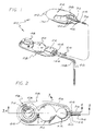
- FIGURE 1 is a partially fragmented perspective diagrammatic view of a preferred form of the medication infusion device of the present invention, illustrating the relationship of the various components of the infusion device to one another, and specifically the relationship of a control assembly relative to a reservoir and a delivery catheter, wherein a portion of the reservoir shell is broken away for illustrative purposes only;
- FIGURE 2 is an enlarged top plan view of the control assembly illustrated in FIG. 1;
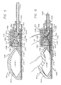
- FIGURE 3 is an enlarged fragmented sectional view taken generally along the line 3-3 of FIG. 2, illustrating the construction of an injection port portion of the control assembly, and the manner in which medication may be injected through a septum of the injection port;
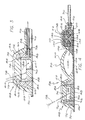
- FIGURE 4 is an enlarged sectional view of the control assembly taken generally along the line 4-4 of FIG. 2, illustrating a recharge fluid flow path through a valve portion of the control assembly to a pump portion;
- FIGURE 5 is an enlarged fragmented sectional view of a portion of the control assembly taken generally along the line 5-5 of FIG. 2 illustrating, particularly, a discharge fluid pathway from the pump through the valve for infusion as directed by the catheter;
- FIGURE 6 is a fragmented sectional view of a portion of the control assembly similar to that illustrated in FIG. 5, illustrating the manner in which percutaneous pressure is utilized to open a normally closed valve and then flush discharged fluids from a pumping chamber within the pump;
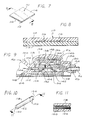
- FIGURE 7 is an enlarged perspective view of a flow restrictor positioned to generally overlie the normally closed valve in the recharge fluid flow path, which flow restrictor limits the rate at which the pump is recharged to restrict the total amount medication which can be pumped into the catheter over a given period of time;
- FIGURE 8 is an enlarged sectional view of the flow restrictor taken generally along the line 8-8 of FIG. 7;
- FIGURE 9 is an enlarged fragmented sectional view taken generally along the line 4-4 of FIG. 2, illustrating, in contrast with FIGS. 4 through 8, the positioning of a second type of flow restrictor in the recharge fluid flow path, wherein the flow restrictor occludes a plurality of wicking fibers encased within a cylindrical impermeable housing;
- FIGURE 10 is an enlarged perspective view of the wick restrictor illustrated in FIG. 9; and
- FIGURE 11 is an enlarged, fragmented sectional view of the wick restrictor taken generally along the line 11-11 of FIG. 10.
- As shown in the drawings for purposes of illustration, the present invention is concerned with an improved medication infusion system, generally designated in the accompanying drawings by the
reference number 20. As illustrated best in FIG. 1, themedication infusion system 20 generally comprises avariable capacity reservoir 22 connected by afluid flow conduit 24 to acatheter 26 which directs medications stored in the reservoir to a specific location within a patient. A fluidflow control assembly 28 is provided to prevent or reduce the likelihood of an inadvertent infusion into the patient of medication stored in thereservoir 22. - The
control assembly 28 used in thesystem 20 is situated between thereservoir 22 and thecatheter 26 to form a portion of thefluid flow conduit 24. Thesystem 20 requires fluid medication to flow through thecontrol assembly 28 before passing into thecatheter 26. With the safety and well-being of the patient and all-important consideration in the employment of thesystem 20, this flow path requirement provides the control over the flow of medication which is critical to the system's safe use. Indeed, thecontrol assembly 28 virtually eliminates the chance of inadvertently infusing more than a very small quantity of medication into the patient by requiring specific sequential and deliberate steps to be taken before a measured volume of fluid can be pumped through thesystem 20. - The
medication infusion system 20 can substantially reduce the cost of treating some illnesses by eliminating the need for constant medical attention or by reducing the number of required visits which need be made with a physician. The overall design of thesystem 20 permits construction into a variety of configurations for use in many types of different applications. Thesystem 20 may be used advantageously by patients requiring regular infusions by minimizing the number of injections received. As will be discussed in greater detail below, themedication infusion system 20 of the present invention includes means for limiting the maximum amount of medication which can be pumped through the system over a given time period. - In accordance with the present invention, and as illustrated with respect to one preferred embodiment in FIGS. 1 through 8, the
variable capacity reservoir 22 comprises asilicone elastomer shell 30 which can expand and collapse to accommodate changing volumes of fluid medication. Thereservoir 22 includes an outlet aperture 32 and anoutlet connector 34 secured within the aperture 32. Theoutlet connector 34 is designed to engage one end of a first segment ofsurgical tubing 36 which extends between thereservoir 30 and thecontrol assembly 28. - A flexible tube 38 having a plurality of tube apertures 40 extends from the reservoir aperture 32 generally rearwardly into the center of the
reservoir 22. The flexible tube 38 is preferably constructed of a silicone elastomer material having sufficient resiliency to maintain a fluid passageway through its center for channeling fluid medication from thereservoir 22 through the aperture 32 and into the first segment ofsurgical tubing 36, notwithstanding a collapse of thereservoir shell 30. Specifically, the flexible tube 38 ensures that fluid medication will be able to exit thereservoir 22 even when thereservoir shell 30 collapses in a manner that would otherwise cover the reservoir outlet aperture 32. Such a collapse of thereservoir shell 30 may result from an emptying of fluid from thereservoir 22 during use of thesystem 20. - In
systems 20 designed for use in the treatment of terminally ill patients, areservoir 22 having a thirty milliliter capacity would normally hold sufficient amounts of morphine or other similar pain killing drugs to supply patients sufficient quantities of medication for several days. Thevariable capacity reservoir 22 can be remotely located from the insertion point of thecatheter 26 in any suitable position as the surgeon chooses, such as in the abdominal cavity, below the ribs or near the clavicle. Indeed, thereservoir 22 can be placed in any soft area of the body which would permit the reservoir to be percutaneously grasped while subcutaneously implanted. To aid in the positioning of thereservoir 22,suture tabs 42 are integrally formed with thereservoir shell 30 to permit the surgeon to anchor thereservoir 22 at the selected location within the patient to prevent migration of the reservoir to an undesirable location. - The first segment of
surgical tubing 36 extends from theoutlet connector 34 of thereservoir 22, to afirst port 44 of thecontrol assembly 28. Anend 46 of thesurgical tubing 36 is fixed within the first port 44 (FIGS. 1, 2 and 4) in any suitable manner which prevents separation of the first segment ofsurgical tubing 36 from thecontrol assembly 28. - The
control assembly 28 includes three primary components: aninjection port 48, apump 50 and a normally closedvalve 52. A rechargefluid flow passageway 54 is provided through thecontrol assembly 28 to direct recharge fluid from thefirst port 44 to thepump 50. Thecontrol assembly 28 also provides an injection portfluid outlet passageway 56 between anoutlet 58 of theinjection port 48, and the rechargefluid flow passageway 54. The fluid passageways 54 and 56 intersect, within thecontrol assembly 28, at aport 60 situated generally adjacent to thefirst port 44 of thecontrol assembly 28. - The
injection port 48 shown in the accompanying drawings (FIGS. 1 through 4) is constructed as part of thecontrol assembly unit 28. Theinjection port 48, however, could be manufactured as a separate component apart from thepump 50 and the normally closedvalve 52, since it does not directly interrelate with the function of the pump and the normally closed valve. Theinjection port 48 comprises an upperelastomeric dome 62, a lower elastomeric reinforcedsheet 64 which generally underlies theentire control assembly 28, and a pair ofbase members 66 and 68 housed within thedome 62 above the reinforcedsheet 64. Theupper dome 62 includes alower flange 70 which is directly sealed to the reinforcedsheet 64 by means of a standard adhesive. Accordingly, thedome 62 and reinforcedsheet 64 present a continuous elastomeric outer housing for theinjection port 48, which helps prevent leakage of drugs injected into theinjection port 48 when subcutaneously implanted. - Extending upwardly from the
dome flange 70 is a frusto-conical side wall 72 which supports an integrally formedseptum 74 in a spaced relation above the lower reinforcedsheet 64. The upper end of theside wall 72 surrounding theseptum 74 provides means for percutaneously manually locating the septum when theinjection port 48 is subcutaneously implanted. More particularly, theside wall 72 includes aridge 76 which circumscribes an upper exterior surface of theseptum 74. Thedome 62 is further provided with an outlet connector passageway through a lower portion thereof. - The
septum 74 comprises a thickened portion of silicone elastomer material having characteristics which permit repeated intermittent puncture by aneedle 78 for injection of medication from a syringe. Such aneedle 78 is preferably 1 mm diameter (twenty-gauge) or smaller. Theseptum 74 includes aseptum flange 80 which generally circumscribes a lower end of the septum beneath theridge portion 76 of theside wall 72. Theseptum flange 80 defines a flange-receiving cavity into which a portion of the outer base member 66 is positioned. - The outer base member 66 is preferably formed of a rigid polypropylene material and includes a generally frusto-
conical ring 82 configured to contiguously engage and support the interior surface of thedome side wall 72. The outer base member 66 further includes a rigidupper flange 84 configured to fit within the flange receiving cavity of thedome 62, and circumscribe theseptum 74 and engage theseptum flange 80. More particularly, the rigidupper flange 84 of the outer base member 66 overlies theseptum flange 80 and provides a rigid barrier between the septum flange and the adjacent portions of thedome side wall 72. Below the rigidupper flange 84 of the outer base member 66, the interior of thering 82 forms an inner cylindrical surface dimensioned to receive and firmly hold theinner base member 68 in an interference fit therein. The outer base member 66 further includes anoutlet connector passageway 86 in the lower end of thering 82, which is aligned with the outlet connector passageway of theelastomeric dome 62. - The
inner base member 68 is preferably formed of a rigid polypropylene material and when positioned within the outer base member 66 it defines, with theseptum 74, aninternal injection chamber 88. Theinner base member 68 is generally cup-shaped and includes afloor 90 and acontinuous wall 92 which extends upwardly from thefloor 90. Thefloor 90 and thewall 92 effectively form a needle shield which prevents theneedle 78 from passing completely through theinjection port 48 after it has entered theinjection chamber 88. An upper septum-engagingsection 94 extends upwardly from the upper edge of thecontinuous wall 92 and, in the assembled configuration, engages the underside of theseptum flange 80. The upper septum-engagingsection 94 meets thecontinuous wall 92 at a shoulder. The upper septum-engagingsection 94 of theinner base member 68 is positioned relative to the outer base member 66 so as to compress theseptum flange 80 between thesection 94 and the rigidupper flange 84. This creates a fluid-tight seal between thebase members 66 and 68, on the one hand, and theseptum 74, on the other, and further tends to improve the resealing characteristics of the septum. - An outlet is provided the
injection port 48, which extends from theinjection chamber 88 exteriorly through thebase members 66 and 68, to receive tubing 96 forming the injection portfluid outlet passageway 56. More specifically, the outlet includes arigid outlet connector 98 which is integrally formed with theinner base member 68. Theoutlet connector 98 provides a passageway for fluid injected into theinjection chamber 88, to pass out of the injection chamber, through thepassageway 56, to either thereservoir 22 or thepump 50. - The
pump 50, which can receive fluids from either thereservoir 22 or theinjection port 48 through the rechargefluid flow passageway 54, comprises a resilientlyflexible crown 100 integrally formed with thedome 62 of theinjection port 48. The reinforcedsheet 64 extends below all three primary components of thecontrol assembly 28, and arigid floor plate 102 overlies the reinforcedsheet 64 beneath the pump and valve components of the control assembly. Apumping chamber 104 is defined between thecrown 100 and thefloor plate 102, and preferably has an evacuation capacity of one milliliter. Importantly, for purposes of the embodiment shown, thecrown 100 is resiliently biased to generally maintain a dome or arch-shape, but can be deformed to lie substantially flat against thefloor plate 102. The volume of thepumping chamber 104 can be customized to accommodate various intended uses for thesystem 20 and the required dosage to be infused into the patient per pumping stroke. By constructing thecrown 100 of the same material as theseptum 74, medication can be injected, if necessary, directly into thepumping chamber 104. In this case, thefloor plate 102 functions as a needle guard, and the puncture site will tend to close upon itself and seal when theneedle 78 is removed. Thepump 50 further includes apump inlet 106 which communicates with the rechargefluid flow passageway 54, and apump outlet 108 in fluid communication with an inlet to the normally closedvalve 52. - The recharge
fluid flow passageway 54 provides means for conducting pump recharge fluid from either theinjection port 48 or thereservoir 22 into thepumping chamber 104. The rechargefluid flow passageway 54 directs the recharge fluid over the top of the normally closedvalve 52 before directing it into thepump inlet 106. This configuration is desirable in order to permit occlusion of a portion of therecharge passageway 54 when the outer housing for the normally closedvalve 52 is pressed downwardly to open the normally closed valve. Additionally, positioned within therecharge passageway 54 are means for restricting the rate of fluid flow through the recharge passageway, which effectively limits the amount of recharge fluid permitted to enter thepumping chamber 104 over a given period of time. - More particularly, in normal operation after fluid is flushed from the
pumping chamber 104 through thepump outlet 108 and through the normally closedvalve 52 which has been opened, the valve is immediately shut by the removal of percutaneous pressure therefrom. Closure of thevalve 52 prevents back flow of fluid through the valve into thepumping chamber 104. Since thecrown 100 is resiliently biased towards its dome-like configuration, a pressure differential is created in thepumping chamber 104 relative to the fluid pressure in thereservoir 22, which tends to draw recharge fluid into thepumping chamber 104 until thecrown 100 returns to its dome-like shape. - In one embodiment of the invention illustrated in FIGS. 4 through 8, the means for restricting the rate of fluid flow through the
recharge passageway 54 comprises a capillary restrictor 110 (FIGS. 7 and 8) which provides a plurality of capillary-like fluid pathways through which the recharge fluid must pass before entering thepumping chamber 104. Thecapillary restrictor 110 includes alower sheet 112 having a generally planar upper surface, and anupper sheet 114 having a plurality ofgrooves 116 extending from one end of thecapillary restrictor 110 to the other. Thecapillary restrictor 110 is positioned within therecharge passageway 54 to overlie the normally closedvalve 52 so that manual manipulation of the normally closed valve to open it to fluid flow simultaneously compresses the restrictor 110 to effectively occlude therecharge passageway 54. - In another embodiment of the invention illustrated in FIGS. 9 through 11, the means for restricting the rate of fluid flow through the
recharge passageway 54 includes awick restrictor 118 positioned to partly occupy thepump inlet 106. Thewick restrictor 118 includes a plurality of wickingfibers 120 situated within an impermeable,cylindrical wick housing 122. Thewick restrictor 118 is positioned within therecharge passageway 54 to ensure that all fluid drawn into thepumping chamber 104 must first pass through therestrictor 118. In this regard, oneend 124 of thewick housing 122 is occluded, for example by means of a silicone sealer, and a plurality ofapertures 126 are provided through the cylindrical wall of thehousing 122 to provide an inlet for thewick restrictor 118. Recharge fluid is then caused to enter thewick restrictor 118 in a direction perpendicular of the length of thefibers 120, and then seep through the fibers before being permitted to pass into thepumping chamber 104. - The normally closed
valve 52 includes a relativelyrigid diaphragm support 128 affixed to a portion of thefloor plate 102, which provides aninlet 130 for the valve. Arigid diaphragm cap 132 is supported upon thediaphragm support 128 and defines, with the diaphragm support, aninlet chamber 134 in fluid communication with thepumping chamber 104, and a valve passageway 136 (formed by the diaphragm cap 132). A resilientlyflexible valve roof 138 is situated over thediaphragm cap 132 to define, with the cap, anoutlet chamber 140 which overlies theinlet chamber 134. Thevalve passageway 136 provides a fluid flow pathway between theinlet chamber 134 and theoutlet chamber 140. - A resiliently
flexible valve diaphragm 142, constructed to form a dome-shaped member, is seated circumferentially upon thediaphragm support 128 within theinlet chamber 134 so that a portion of the diaphragm is normally positioned adjacent to thevalve passageway 136. Thevalve diaphragm 142 is provided a plurality ofdiaphragm apertures 144. Unless forcibly displaced away from the portion of thecap 132 surrounding thevalve passageway 136, thediaphragm 142 forms a seal which prevents any fluid flow through the normally closedvalve 52. It is preferred that thecap 132 and thediaphragm 142 be constructed of materials which will not stick to one another, particularly after long periods of storage. - Some exterior surfaces of the
diaphragm support 128, thecap 132 and theroof 138 define portions of therecharge passageway 54. Avalve housing 146 also defines portions of therecharge passageway 54. A portion of thevalve roof 138 overlying theoutlet chamber 140 includes a downwardly extendingdiaphragm displacement finger 148 positioned directly above thevalve passageway 136. Thedisplacement finger 148 is situated for travel through thevalve passageway 136 when pressed downwardly, and the diameter of the finger is small enough to prevent occlusion of thevalve passageway 136 when the finger is pressed therethrough. When enough pressure is applied, thefinger 148 causes thevalve diaphragm 142 to flex downwardly a sufficient distance to break the valve seal and allow fluid to pass through the valve passageway 136 (FIG. 6). Thehousing 146, thevalve roof 138 and thediaphragm 142 are each sufficiently resilient to return to their normal configurations and, consequently, close the normally closedvalve 52 to fluid flow when the deforming pressure is removed. The inclusion of such a normally closedvalve 52 in thesystem 20 enhances the system's utility and safety by preventing the flow of fluid through a discharge fluid flow conduit, partially defined by the normally closedvalve 52, in the absence of direct, selectively applied percutaneous pressure on thecontrol assembly 28. - A
valve outlet 150 receives fluid from theoutlet chamber 140 and directs it into a secondcontrol assembly port 152. As shown best in FIGS. 5 and 6, fixed within thesecond port 152 is second segment ofsurgical tubing 154 which conducts fluids discharged from thepumping chamber 104 from thecontrol assembly 28 to thecatheter 26. - The
catheter 26 is preferably formed of a barium-impregnated silicone elastomer material which is radiopaque for detection by X-ray photography. Acatheter inlet 156 is attached to the second segment ofsurgical tubing 154, and fluid medication exiting thecontrol assembly 28 is directed by thecatheter 26 for infusion into a specific portion of the body. For example, in the case of terminally ill patients acatheter 26 can be inserted into the lateral ventricle of the patient's brain. When such catheter placement is contemplated, acatheter clip 158, as shown in FIG. 1, can be advantageously utilized to hold thecatheter 26 in place adjacent to a burr hole through the skull. - Although the
injection port 48, thepump 50 and the normally closedvalve 52 are shown in the exemplary drawings as combined to form theunitary control assembly 28, each component may be separately constructed to form individual system components which can be connected to one another by a conduit such as flexible surgical tubing. - In use, the
medication infusion system 20 provides a convenient means for percutaneously controlling the flow of fluid through the subcutaneously implanted infusion system, and yet includes important safety features which prevent the inadvertent, accidental infusion of medication, and further limits the maximum amount of medication which can be infused through the system over a given time period. To use thesystem 20, it must first be subcutaneously implanted. Preferably, thecontrol assembly 28 is placed over a hard boney surface to provide sufficient resistance to percutaneous pressure which will be applied thereto. Often, when initially implanted, thesystem 20 has previously been primed with a sterile saline solution which must be evacuated and replaced with the desired medication. - Medication is introduced into the
infusion system 20 through injection into theinjection chamber 88 of theinjection port 48. Medication injected into theinjection chamber 88 flows through the injection portfluid outlet passageway 56 to theport 60 which intersects with a portion of the rechargefluid flow passageway 54. Here, the injected medication will take the path of least resistance to either fill thereservoir 22 or thepumping chamber 104. When filling thereservoir 22, the fluid medication flows out of thecontrol assembly 28 through the firstcontrol assembly port 44, through the first segment ofsurgical tubing 36 connecting the control assembly to the reservoir, and through theoutlet connector 34 fixed within the reservoir aperture 32. - If the
pump crown 100 has been depressed to flush priming fluid from thepumping chamber 104, it will attempt to regain its original dome shape. This will create a pressure differential, assuming the normally closedvalve 52 is closed, which will draw medication through the rechargefluid flow passageway 54 from either theinjection chamber 88 or thereservoir 22. The fluid flow restrictor, whether it be thecapillary restrictor 110 or thewick restrictor 118, effectively limits the rate at which thepumping chamber 104 is permitted to draw-in recharge fluids. - To begin the infusion of medication to the patient through the
system 20, the normally closedvalve 52 must be opened by applying percutaneous pressure thereto, to permit medication in thepumping chamber 104 to be discharged through thepump outlet 108. The normally closedvalve 52 is opened by manually applying percutaneous downward pressure to the valve housing 146 (FIG. 6). Such downward percutaneous pressure occludes therecharge passageway 54 and forces thedisplacement finger 148 downwardly through thevalve passageway 136 to disengage thevalve diaphragm 142 from the valve seat. Thus, by simply pressing downwardly on thevalve housing 146, a discharge fluid conduit is opened through thevalve 52 to permit medication to be flushed from thepump 50, while simultaneously occluding therecharge passageway 54 and thereby preventing any fluid flow out of thepump inlet 106. When using the capillary restrictor illustrated in FIGS. 7 and 8, theupper sheet 114 collapses upon thelower sheet 112 to occlude the capillary-like grooves 116. When thewick restrictor 118 is utilized (FIGS. 9 through 11), the channelling of recharge fluid over the top of thevalve 52 permits a portion of therecharge passageway 54 to be occluded by the same downward finger pressure. - With the
valve 52 opened, medication in thepumping chamber 104 can be discharged through thepump outlet 108 and the normally closedvalve 52 by applying downward percutaneous pressure to thepump 50. This is accomplished by pressing thepump crown 100 downwardly to collapse the pump crown against thefloor plate 102. Medication within thepumping chamber 104 is caused to flow from thepump outlet 108 through the valve to the secondcontrol assembly port 152, and into the second segment ofsurgical tubing 154 for delivery to thecatheter 26. - After the medication is flushed from the
pumping chamber 104, thevalve 52 is closed by simply removing the percutaneous pressure applied thereto, and therecharge passageway 54 is opened to permit fluid flow into thepump 50 when the valve is closed. The steps of closing thevalve 52 and opening therecharge passageway 54 occur simultaneously upon the withdrawal of percutaneous pressure from the valve. Thepump crown 100 thereafter attempts to regain its original dome-shaped configuration, drawing recharge fluid into thepumping chamber 104 at a rate controlled by either thecapillary restrictor 110 or thewick restrictor 118. - The
medication infusion system 20 described above can greatly ease the burden of medical personnel and hospital facilities by providing means for internally storing a large quantity of medication which is to be administered to a patient over an extended period of time. Moreover, various apparatuses can be added to thesystem 20 for a multitude of purposes, such as the provision of a burr hole reservoir situated adjacent to the skull to facilitate injection of medications directly into the brain. - Although two particular embodiments of the invention have been described in detail for purposes of illustration, various modifications of each may be made without departing from the scope of the invention. Accordingly, the invention is not to be limited, except as by the appended claims.
Claims (10)
- An infusion reservoir and pump system, including means (48) for receiving medication into the system by injection; a reservoir (22) fluidly connected to the receiving means in a manner permitting the subcutaneous transfer of medication from the receiving means to the reservoir; a catheter (26) for directing the medication to a specific location in a body, the catheter having a catheter inlet and being positionable within the body independently of the position of the reservoir; means (24) for conducting the medication from the reservoir to the catheter inlet; and means (28) for controlling the flow of medication from the reservoir to the catheter, the controlling means forming a portion of the conducting means and including normally closed valve means (52) and a pump (50) for flushing a measured quantity of medication into the catheter when the normally closed valve means is opened, the valve means and the pump being actuated by manual percutaneous manipulation characterised by means (110, 118) for restricting the flow of medication from the reservoir to the pump, and thus limiting the rate the pump is recharged, to restrict the total amount of medication which can be pumped into the catheter over a given period of time, the restricting means being positioned within the normally closed valve means and including a fluid pathway (54) through which medication must pass before entering the pump, wherein manipulation of the valve means to open it occludes the fluid pathway to close a portion of the conducting means defined by the restricting means.
- A system as set forth in claim 1, wherein the means for receiving medication into the system by injection comprises an injection port (48) including an elastomeric outer housing (62) having an integral elastomeric septum (74), a first base member (66) situated within the outer housing and contiguously engaging a peripheral portion (80) of the septum, a second base member (68) situated within the first base member and within the outer housing, wherein the second base member contiguously engages the peripheral portion of the septum opposite to the first base member, such that the septum is compressed between the first and second base members, and an outlet (98) extending from an internal chamber (88) between the septum and the second base member, exteriorly through the outer housing.
- A system as set forth in claim 2, wherein the elastomeric outer housing of the injection port includes an upper dome (62) attached to a lower reinforced sheet (64), the upper dome including a lower flange (70) sealed to the reinforced sheet, a frusto-conical side wall (72) extending upwardly from the lower flange, and the septum which is integrally formed with the side wall and supported thereby in spaced relation to the lower reinforced sheet.
- A system as set forth in claim 3, wherein the peripheral portion of the septum extends circumferentially outwardly from the body of the septum between the side wall and the lower reinforced sheet, and wherein the first base member comprises a generally frusto-conical ring (82) configured to engage and support an interior surface of the side wall, and a rigid upper flange (84) which overlies the peripheral portion of the septum to provide a rigid barrier between the peripheral portion of the septum and the adjacent side wall portions, wherein the upper flange circumscribes the septum and engages the peripheral portion of the septum.
- A system as set forth in claim 4, wherein the second base member is cup-shaped and includes a floor (90) and a continuous wall (92) which extends upwardly therefrom, wherein the continuous wall projects frog the floor to engage an inner surface of the first base member in an interference fit, wherein the second base member, with the septum, defines the internal injection chamber and forms a needle shield adjacent to the lower reinforced sheet, the second base member including an upper septum-engaging section (94) which extends upwardly from the continuous wall to underlie the peripheral portion of the septum and compress the peripheral portion of the septum between the upper flange of the first base member and the upper septum-engaging section of the second base member.
- A system as set forth in claim 1, wherein the normally closed valve means includes a resiliently flexible valve body (146) which defines a fluid flow passageway therethrough, a valve member (142) positioned within the fluid flow passageway to occlude the valve means, a valve inlet (130) in fluid communication with the pump, a valve outlet (150) in fluid communication with the catheter inlet, and a valve passageway (136) situated directly between the valve inlet and outlet, wherein the valve member is resiliently biased to occlude the valve passageway.
- A system as set forth in claim 6, wherein the normally closed valve means includes a displacement finger (148) which is situated and configured to displace the valve member and open the valve means to fluid flow therethrough when the valve means is actuated by manual percutaneous manipulation.
- A system as set forth in claim 7, wherein the restricting means fluid pathway (110) is capillary-like, and is positioned within the valve body relative to the displacement finger so that manipulation of the valve means to move the displacement finger occludes the capillary-like fluid pathway.
- A system as set forth in claim 1, wherein the restricting means includes a wick restrictor (118) having a plurality of wicking fibers (120) situated within an impermeable wick housing (122), wherein the wick restrictor is positioned within a portion of the conducting means such that all fluid drawn into the pump must first pass through the wick restrictor.
- A system as set forth in claim 9, wherein one end (124) of the wick housing is occluded, and an inlet (126) is provided adjacent to the occluded end through a wall of the wick housing.
Applications Claiming Priority (2)
| Application Number | Priority Date | Filing Date | Title |
|---|---|---|---|
| US503426 | 1990-04-02 | ||
| US07/503,426 US5152753A (en) | 1990-04-02 | 1990-04-02 | Medication infusion device with dose recharge restriction |
Publications (2)
| Publication Number | Publication Date |
|---|---|
| EP0450186A1 EP0450186A1 (en) | 1991-10-09 |
| EP0450186B1 true EP0450186B1 (en) | 1995-02-15 |
Family
ID=24002046
Family Applications (1)
| Application Number | Title | Priority Date | Filing Date |
|---|---|---|---|
| EP90125189A Expired - Lifetime EP0450186B1 (en) | 1990-04-02 | 1990-12-21 | Medication infusion device with dose recharge restriction |
Country Status (6)
| Country | Link |
|---|---|
| US (1) | US5152753A (en) |
| EP (1) | EP0450186B1 (en) |
| JP (1) | JPH0824720B2 (en) |
| AT (1) | ATE118360T1 (en) |
| CA (1) | CA2030767C (en) |
| DE (1) | DE69017004T2 (en) |
Cited By (4)
| Publication number | Priority date | Publication date | Assignee | Title |
|---|---|---|---|---|
| US8547239B2 (en) | 2009-08-18 | 2013-10-01 | Cequr Sa | Methods for detecting failure states in a medicine delivery device |
| US8672873B2 (en) | 2009-08-18 | 2014-03-18 | Cequr Sa | Medicine delivery device having detachable pressure sensing unit |
| US9005169B2 (en) | 2007-10-16 | 2015-04-14 | Cequr Sa | Cannula insertion device and related methods |
| US9211378B2 (en) | 2010-10-22 | 2015-12-15 | Cequr Sa | Methods and systems for dosing a medicament |
Families Citing this family (70)
| Publication number | Priority date | Publication date | Assignee | Title |
|---|---|---|---|---|
| US5728061A (en) * | 1988-10-07 | 1998-03-17 | Ahmed; Abdul Mateen | Device and method for treating hydrocephalus |
| US5336188A (en) * | 1989-06-16 | 1994-08-09 | Science Incorporated | Fluid delivery apparatus having a stored energy source |
| DK8391A (en) * | 1991-01-18 | 1992-07-19 | Uno Plast As | Suction pump for use in extraction of body fluids from the body cavity |
| US5431634A (en) * | 1992-03-06 | 1995-07-11 | Baxter International Inc. | Ambulatory pump |
| DE4402380A1 (en) * | 1994-01-27 | 1995-08-03 | Hans Peter Prof Dr Med Zenner | Implantable dosing system |
| US5776103A (en) * | 1995-10-11 | 1998-07-07 | Science Incorporated | Fluid delivery device with bolus injection site |
| US5871484A (en) * | 1995-11-09 | 1999-02-16 | General Orthopedics | Apparatus and method for administering a biologically active substance to a bone |
| US6186982B1 (en) * | 1998-05-05 | 2001-02-13 | Elan Corporation, Plc | Subcutaneous drug delivery device with improved filling system |
| JPH11190281A (en) * | 1997-10-20 | 1999-07-13 | Seiko Instruments Inc | Air pump, air chamber device and wrist watch with air chamber device |
| SE9704769D0 (en) * | 1997-12-19 | 1997-12-19 | Astra Ab | Medical device |
| US6048328A (en) * | 1998-02-02 | 2000-04-11 | Medtronic, Inc. | Implantable drug infusion device having an improved valve |
| AU2570999A (en) * | 1998-02-02 | 1999-08-16 | Medtronic, Inc. | Implantable drug infusion device having a safety valve |
| US6193682B1 (en) | 1998-03-16 | 2001-02-27 | Abdul Mateen Ahmed | Low profile neonatal hydrocephalus device and methods |
| US6283944B1 (en) * | 1998-04-30 | 2001-09-04 | Medtronic, Inc. | Infusion systems with patient-controlled dosage features |
| US8177762B2 (en) | 1998-12-07 | 2012-05-15 | C. R. Bard, Inc. | Septum including at least one identifiable feature, access ports including same, and related methods |
| US6287293B1 (en) * | 1999-09-28 | 2001-09-11 | C. R. Bard, Inc. | Method and apparatus for locating the injection point of an implanted medical device |
| US6530903B2 (en) | 2000-02-24 | 2003-03-11 | Xiping Wang | Safety syringe |
| US6666845B2 (en) | 2001-01-04 | 2003-12-23 | Advanced Neuromodulation Systems, Inc. | Implantable infusion pump |
| JP4371657B2 (en) * | 2001-03-01 | 2009-11-25 | ディヴィッド エイ ワトソン | Indwelling catheter assembly prevents ingrowth |
| MXPA03011015A (en) | 2001-06-01 | 2004-03-19 | I Flow Corp | Large volume bolus device and method. |
| EP1476209B1 (en) * | 2002-02-18 | 2008-07-30 | Danfoss A/S | Device for administering of medication in fluid form |
| US7115108B2 (en) * | 2002-04-02 | 2006-10-03 | Becton, Dickinson And Company | Method and device for intradermally delivering a substance |
| GB2389791B (en) | 2002-04-30 | 2006-12-13 | Steven Gill | Implantable drug delivery pump |
| US6936035B2 (en) * | 2002-12-31 | 2005-08-30 | I-Flow Corporation | Patient controlled drug administration device |
| EP1594562B1 (en) | 2003-01-28 | 2017-09-13 | CeQur SA | Capillary carrier with leak supervision |
| US20050124980A1 (en) * | 2003-12-03 | 2005-06-09 | Sanders Scott W. | Port stem marking for catheter placement |
| US20050131388A1 (en) * | 2003-12-16 | 2005-06-16 | Henrich Cheng | Embedded spinal injector |
| KR100640952B1 (en) * | 2004-12-29 | 2006-11-02 | 동부일렉트로닉스 주식회사 | method for forming metal line of semiconductor device |
| US20060184091A1 (en) * | 2005-02-14 | 2006-08-17 | Alcon, Inc. | Liquefaction handpiece |
| EP1858565B1 (en) | 2005-03-04 | 2021-08-11 | C.R. Bard, Inc. | Access port identification systems and methods |
| US7947022B2 (en) * | 2005-03-04 | 2011-05-24 | C. R. Bard, Inc. | Access port identification systems and methods |
| US9474888B2 (en) | 2005-03-04 | 2016-10-25 | C. R. Bard, Inc. | Implantable access port including a sandwiched radiopaque insert |
| US8029482B2 (en) | 2005-03-04 | 2011-10-04 | C. R. Bard, Inc. | Systems and methods for radiographically identifying an access port |
| US20060212037A1 (en) * | 2005-03-16 | 2006-09-21 | Alcon, Inc. | Pumping chamber for a liquefaction handpiece |
| US10307581B2 (en) | 2005-04-27 | 2019-06-04 | C. R. Bard, Inc. | Reinforced septum for an implantable medical device |
| EP1874393B1 (en) | 2005-04-27 | 2017-09-06 | C.R.Bard, Inc. | Infusion apparatuses |
| JP5149158B2 (en) | 2005-04-27 | 2013-02-20 | シー・アール・バード・インコーポレーテッド | Injection device and method related thereto |
| US8034029B2 (en) | 2005-05-25 | 2011-10-11 | Palyon Medical (Bvi) Limited | Multi-reservoir implantable pump with patient controlled actuation |
| US7708730B2 (en) | 2006-01-30 | 2010-05-04 | Palyon Medical (Bvi) Limited | Template system for multi-reservoir implantable pump |
| US9265912B2 (en) | 2006-11-08 | 2016-02-23 | C. R. Bard, Inc. | Indicia informative of characteristics of insertable medical devices |
| US9642986B2 (en) | 2006-11-08 | 2017-05-09 | C. R. Bard, Inc. | Resource information key for an insertable medical device |
| EP3269417A1 (en) | 2007-06-20 | 2018-01-17 | Medical Components, Inc. | Implantable access port with molded and/or radiopaque indicia |
| CA2693972C (en) | 2007-07-19 | 2019-01-15 | Medical Components, Inc. | Venous access port assembly with x-ray discernable indicia |
| WO2009012395A1 (en) | 2007-07-19 | 2009-01-22 | Innovative Medical Devices, Llc | Venous access port assembly with x-ray discernable indicia |
| US8057437B2 (en) * | 2007-08-31 | 2011-11-15 | Hospira, Inc. | Radially sealing vavle for an infusion set |
| US9579496B2 (en) | 2007-11-07 | 2017-02-28 | C. R. Bard, Inc. | Radiopaque and septum-based indicators for a multi-lumen implantable port |
| DE102008030942A1 (en) | 2008-07-02 | 2010-01-07 | Christoph Miethke Gmbh & Co Kg | Cerebrospinal fluid drainage |
| US8109912B2 (en) * | 2008-09-12 | 2012-02-07 | Calibra Medical, Inc. | Wearable infusion assembly |
| US8291933B2 (en) * | 2008-09-25 | 2012-10-23 | Novartis Ag | Spring-less check valve for a handpiece |
| BRPI0919890B8 (en) | 2008-10-31 | 2019-09-24 | Bard Inc C R | access port to provide subcutaneous access to a patient, and force injectable access port |
| US8932271B2 (en) | 2008-11-13 | 2015-01-13 | C. R. Bard, Inc. | Implantable medical devices including septum-based indicators |
| US11890443B2 (en) | 2008-11-13 | 2024-02-06 | C. R. Bard, Inc. | Implantable medical devices including septum-based indicators |
| WO2010080081A2 (en) * | 2009-01-09 | 2010-07-15 | Sidney Rohrscheib | Onlay access port |
| US8230744B2 (en) | 2009-05-06 | 2012-07-31 | Cequr Sa | Low-dead volume microfluidic circuit and methods |
| US7967797B2 (en) * | 2009-05-19 | 2011-06-28 | Nexus Medical, Llc | Intravascular valve component with improved valve positioning |
| WO2011005847A1 (en) | 2009-07-07 | 2011-01-13 | C. R. Bard, Inc. | Extensible internal bolster for a medical device |
| JP2013510652A (en) | 2009-11-17 | 2013-03-28 | シー・アール・バード・インコーポレーテッド | Overmolded access port including locking feature and identification feature |
| US8814829B2 (en) | 2010-08-12 | 2014-08-26 | Baxter International Inc. | Drug delivery device for fluid restricted patients |
| USD682416S1 (en) | 2010-12-30 | 2013-05-14 | C. R. Bard, Inc. | Implantable access port |
| USD676955S1 (en) | 2010-12-30 | 2013-02-26 | C. R. Bard, Inc. | Implantable access port |
| US8591456B2 (en) | 2011-12-28 | 2013-11-26 | Palyon Medical (Bvi) Limited | Multiple reservoir programmable pump |
| US10517892B2 (en) | 2013-10-22 | 2019-12-31 | Medtronic Minimed, Inc. | Methods and systems for inhibiting foreign-body responses in diabetic patients |
| US20150133861A1 (en) | 2013-11-11 | 2015-05-14 | Kevin P. McLennan | Thermal management system and method for medical devices |
| US10143795B2 (en) | 2014-08-18 | 2018-12-04 | Icu Medical, Inc. | Intravenous pole integrated power, control, and communication system and method for an infusion pump |
| ES2809505T3 (en) | 2015-05-26 | 2021-03-04 | Icu Medical Inc | Disposable infusion fluid delivery device for programmable delivery of high volume drugs |
| NL2015004B1 (en) * | 2015-06-19 | 2017-01-24 | Ipadic B V | Implantable infusion system. |
| DE102016214325A1 (en) * | 2016-08-03 | 2018-02-08 | B. Braun Melsungen Ag | Elastomeric reservoir of an infusion pump |
| US11197949B2 (en) | 2017-01-19 | 2021-12-14 | Medtronic Minimed, Inc. | Medication infusion components and systems |
| USD939079S1 (en) | 2019-08-22 | 2021-12-21 | Icu Medical, Inc. | Infusion pump |
| WO2022173620A1 (en) * | 2021-02-12 | 2022-08-18 | Medtronic, Inc. | Implantable microsphere reservoir |
Family Cites Families (28)
| Publication number | Priority date | Publication date | Assignee | Title |
|---|---|---|---|---|
| BE664424A (en) * | ||||
| US342131A (en) * | 1886-05-18 | Island | ||
| US3503402A (en) * | 1966-03-23 | 1970-03-31 | Rudolf R Schulte | Shunt device |
| US3527220A (en) * | 1968-06-28 | 1970-09-08 | Fairchild Hiller Corp | Implantable drug administrator |
| US3756243A (en) * | 1971-09-23 | 1973-09-04 | R Schulte | Flow control system for physiological drainage |
| US3768508A (en) * | 1972-01-24 | 1973-10-30 | R Schulte | Valve for controllable release of entrapped body fluids |
| US3827439A (en) * | 1972-10-30 | 1974-08-06 | Heyer Schulte Corp | Plug valve for physiological shunt systems |
| US4360019A (en) * | 1979-02-28 | 1982-11-23 | Andros Incorporated | Implantable infusion device |
| US4364395A (en) * | 1981-06-30 | 1982-12-21 | American Heyer-Schulte Corporation | Low profile shunt system |
| US4544371A (en) * | 1982-10-05 | 1985-10-01 | American Hospital Supply Corporation | Implantable metered dose drug delivery system |
| US4557722A (en) * | 1983-04-13 | 1985-12-10 | Cordis Corporation | Fill port for an implantable dispensing system |
| US4552553A (en) * | 1983-06-30 | 1985-11-12 | Pudenz-Schulte Medical Research Corp. | Flow control valve |
| US4560375A (en) * | 1983-06-30 | 1985-12-24 | Pudenz-Schulte Medical Research Corp. | Flow control valve |
| US4557721A (en) * | 1983-11-29 | 1985-12-10 | Cordis Corporation | Servo valve |
| US4668231A (en) * | 1984-02-15 | 1987-05-26 | Cordis Corporation | Implantable hand-operable dispensers for fluid medicaments |
| US4588394A (en) * | 1984-03-16 | 1986-05-13 | Pudenz-Schulte Medical Research Corp. | Infusion reservoir and pump system |
| US4681560A (en) * | 1984-03-16 | 1987-07-21 | Pudenz-Schulte Medical Research Corp. | Subcutaneous infusion reservoir and pump system |
| US4634427A (en) * | 1984-09-04 | 1987-01-06 | American Hospital Supply Company | Implantable demand medication delivery assembly |
| EP0177250A3 (en) * | 1984-10-01 | 1988-02-03 | Cook Incorporated | Implantable insulin administration device |
| JPS61234870A (en) * | 1984-12-19 | 1986-10-20 | クリエートメディック株式会社 | Skin embedding type reservoir |
| US4681564A (en) * | 1985-10-21 | 1987-07-21 | Landreneau Michael D | Catheter assembly having balloon extended flow path |
| US4681570A (en) * | 1985-12-26 | 1987-07-21 | Dalton Michael J | Peritoneal catheter |
| FR2599260A1 (en) * | 1986-04-24 | 1987-12-04 | Centre Nat Rech Scient | RECHARGEABLE IMPLANTABLE DEVICE FOR DOSED AND REPEATED MEDICINAL SELF INJECTION |
| JPS63252170A (en) * | 1987-04-08 | 1988-10-19 | 富士システムズ株式会社 | Body embedding type catheter equipped with reservoir |
| US4898585A (en) * | 1988-05-18 | 1990-02-06 | Baxter Healthcare Corporation | Implantable patient-activated fluid delivery device with bolus injection port |
| US4898584A (en) * | 1988-05-18 | 1990-02-06 | Baxter Healthcare Corporation | Implantable patient-activated fluid delivery device |
| US4898583A (en) * | 1988-05-18 | 1990-02-06 | Baxter Healthcare Corporation | Implantable patient-activated fluid delivery device and outlet valve therefor |
| US4898582A (en) * | 1988-08-09 | 1990-02-06 | Pharmetrix Corporation | Portable infusion device assembly |
-
1990
- 1990-04-02 US US07/503,426 patent/US5152753A/en not_active Expired - Lifetime
- 1990-11-23 CA CA002030767A patent/CA2030767C/en not_active Expired - Fee Related
- 1990-12-21 DE DE69017004T patent/DE69017004T2/en not_active Expired - Fee Related
- 1990-12-21 EP EP90125189A patent/EP0450186B1/en not_active Expired - Lifetime
- 1990-12-21 AT AT90125189T patent/ATE118360T1/en not_active IP Right Cessation
-
1991
- 1991-01-11 JP JP3001900A patent/JPH0824720B2/en not_active Expired - Fee Related
Cited By (9)
| Publication number | Priority date | Publication date | Assignee | Title |
|---|---|---|---|---|
| US9005169B2 (en) | 2007-10-16 | 2015-04-14 | Cequr Sa | Cannula insertion device and related methods |
| US9968747B2 (en) | 2007-10-16 | 2018-05-15 | Cequr Sa | Cannula insertion device and related methods |
| US8547239B2 (en) | 2009-08-18 | 2013-10-01 | Cequr Sa | Methods for detecting failure states in a medicine delivery device |
| US8672873B2 (en) | 2009-08-18 | 2014-03-18 | Cequr Sa | Medicine delivery device having detachable pressure sensing unit |
| US9022972B2 (en) | 2009-08-18 | 2015-05-05 | Cequr Sa | Medicine delivery device having detachable pressure sensing unit |
| US9039654B2 (en) | 2009-08-18 | 2015-05-26 | Cequr Sa | Medicine delivery device having detachable pressure sensing unit |
| US9174009B2 (en) | 2009-08-18 | 2015-11-03 | Cequr Sa | Methods for detecting failure states in a medicine delivery device |
| US10300196B2 (en) | 2009-08-18 | 2019-05-28 | Cequr Sa | Medicine delivery device having detachable pressure sensing unit |
| US9211378B2 (en) | 2010-10-22 | 2015-12-15 | Cequr Sa | Methods and systems for dosing a medicament |
Also Published As
| Publication number | Publication date |
|---|---|
| CA2030767C (en) | 1995-04-04 |
| DE69017004T2 (en) | 1995-06-08 |
| CA2030767A1 (en) | 1991-10-03 |
| US5152753A (en) | 1992-10-06 |
| JPH0747136A (en) | 1995-02-21 |
| EP0450186A1 (en) | 1991-10-09 |
| DE69017004D1 (en) | 1995-03-23 |
| ATE118360T1 (en) | 1995-03-15 |
| JPH0824720B2 (en) | 1996-03-13 |
Similar Documents
| Publication | Publication Date | Title |
|---|---|---|
| EP0450186B1 (en) | Medication infusion device with dose recharge restriction | |
| US5085644A (en) | Sterilizable medication infusion device with dose recharge restriction | |
| US4816016A (en) | Subcutaneous infusion reservoir and pump system | |
| US4681560A (en) | Subcutaneous infusion reservoir and pump system | |
| US4588394A (en) | Infusion reservoir and pump system | |
| US6852106B2 (en) | Implantable refillable and ported controlled release drug delivery device | |
| US4634427A (en) | Implantable demand medication delivery assembly | |
| US5137529A (en) | Injection port | |
| EP1075291B1 (en) | Infusion systems with patient-controlled dosage features | |
| US4581020A (en) | Medication delivery device and system for percutaneous administration of medication | |
| US4464178A (en) | Method and apparatus for administration of fluids | |
| US4544371A (en) | Implantable metered dose drug delivery system | |
| US5395324A (en) | Apparatus for the reliable filling of the container of an infusion pump | |
| US8372039B2 (en) | Infusion pump system | |
| US6997914B2 (en) | Implantable access port | |
| US4761158A (en) | Subcutaneous infusion reservoir and pump system | |
| US9993592B2 (en) | Cartridge system for delivery of medicament | |
| EP0999865A1 (en) | Catheter assembly for percutaneous access to subcutaneous port | |
| WO1995008359A1 (en) | Medication administration apparatus | |
| AU2001297716A1 (en) | Implantable refillable and rate controlled drug delivery device | |
| WO2013058911A1 (en) | Mesh protection system | |
| Gianino et al. | Implantable Delivery Systems |
Legal Events
| Date | Code | Title | Description |
|---|---|---|---|
| PUAI | Public reference made under article 153(3) epc to a published international application that has entered the european phase |
Free format text: ORIGINAL CODE: 0009012 |
|
| AK | Designated contracting states |
Kind code of ref document: A1 Designated state(s): AT BE CH DE DK ES FR GB GR IT LI LU NL SE |
|
| 17P | Request for examination filed |
Effective date: 19910909 |
|
| 17Q | First examination report despatched |
Effective date: 19931026 |
|
| GRAA | (expected) grant |
Free format text: ORIGINAL CODE: 0009210 |
|
| AK | Designated contracting states |
Kind code of ref document: B1 Designated state(s): AT BE CH DE DK ES FR GB GR IT LI LU NL SE |
|
| PG25 | Lapsed in a contracting state [announced via postgrant information from national office to epo] |
Ref country code: IT Free format text: LAPSE BECAUSE OF FAILURE TO SUBMIT A TRANSLATION OF THE DESCRIPTION OR TO PAY THE FEE WITHIN THE PRE;WARNING: LAPSES OF ITALIAN PATENTS WITH EFFECTIVE DATE BEFORE 2007 MAY HAVE OCCURRED AT ANY TIME BEFORE 2007. THE CORRECT EFFECTIVE DATE MAY BE DIFFERENT FROM THE ONE RECORDED.SCRIBED TIME-LIMIT Effective date: 19950215 Ref country code: GR Free format text: LAPSE BECAUSE OF FAILURE TO SUBMIT A TRANSLATION OF THE DESCRIPTION OR TO PAY THE FEE WITHIN THE PRESCRIBED TIME-LIMIT Effective date: 19950215 Ref country code: ES Free format text: THE PATENT HAS BEEN ANNULLED BY A DECISION OF A NATIONAL AUTHORITY Effective date: 19950215 Ref country code: AT Effective date: 19950215 Ref country code: DK Effective date: 19950215 |
|
| REF | Corresponds to: |
Ref document number: 118360 Country of ref document: AT Date of ref document: 19950315 Kind code of ref document: T |
|
| REF | Corresponds to: |
Ref document number: 69017004 Country of ref document: DE Date of ref document: 19950323 |
|
| ET | Fr: translation filed | ||
| PG25 | Lapsed in a contracting state [announced via postgrant information from national office to epo] |
Ref country code: SE Effective date: 19950515 |
|
| PGFP | Annual fee paid to national office [announced via postgrant information from national office to epo] |
Ref country code: FR Payment date: 19951212 Year of fee payment: 6 |
|
| PG25 | Lapsed in a contracting state [announced via postgrant information from national office to epo] |
Ref country code: LU Free format text: LAPSE BECAUSE OF NON-PAYMENT OF DUE FEES Effective date: 19951231 |
|
| PLBE | No opposition filed within time limit |
Free format text: ORIGINAL CODE: 0009261 |
|
| STAA | Information on the status of an ep patent application or granted ep patent |
Free format text: STATUS: NO OPPOSITION FILED WITHIN TIME LIMIT |
|
| 26N | No opposition filed | ||
| PG25 | Lapsed in a contracting state [announced via postgrant information from national office to epo] |
Ref country code: FR Effective date: 19970829 |
|
| REG | Reference to a national code |
Ref country code: FR Ref legal event code: ST |
|
| REG | Reference to a national code |
Ref country code: GB Ref legal event code: IF02 |
|
| PGFP | Annual fee paid to national office [announced via postgrant information from national office to epo] |
Ref country code: GB Payment date: 20041104 Year of fee payment: 15 |
|
| PGFP | Annual fee paid to national office [announced via postgrant information from national office to epo] |
Ref country code: NL Payment date: 20041111 Year of fee payment: 15 |
|
| PGFP | Annual fee paid to national office [announced via postgrant information from national office to epo] |
Ref country code: DE Payment date: 20041230 Year of fee payment: 15 |
|
| PGFP | Annual fee paid to national office [announced via postgrant information from national office to epo] |
Ref country code: CH Payment date: 20050107 Year of fee payment: 15 |
|
| PGFP | Annual fee paid to national office [announced via postgrant information from national office to epo] |
Ref country code: BE Payment date: 20050113 Year of fee payment: 15 |
|
| PG25 | Lapsed in a contracting state [announced via postgrant information from national office to epo] |
Ref country code: GB Free format text: LAPSE BECAUSE OF NON-PAYMENT OF DUE FEES Effective date: 20051221 |
|
| PG25 | Lapsed in a contracting state [announced via postgrant information from national office to epo] |
Ref country code: CH Free format text: LAPSE BECAUSE OF NON-PAYMENT OF DUE FEES Effective date: 20051231 Ref country code: BE Free format text: LAPSE BECAUSE OF NON-PAYMENT OF DUE FEES Effective date: 20051231 Ref country code: LI Free format text: LAPSE BECAUSE OF NON-PAYMENT OF DUE FEES Effective date: 20051231 |
|
| PG25 | Lapsed in a contracting state [announced via postgrant information from national office to epo] |
Ref country code: DE Free format text: LAPSE BECAUSE OF NON-PAYMENT OF DUE FEES Effective date: 20060701 Ref country code: NL Free format text: LAPSE BECAUSE OF NON-PAYMENT OF DUE FEES Effective date: 20060701 |
|
| REG | Reference to a national code |
Ref country code: CH Ref legal event code: PL |
|
| GBPC | Gb: european patent ceased through non-payment of renewal fee |
Effective date: 20051221 |
|
| NLV4 | Nl: lapsed or anulled due to non-payment of the annual fee |
Effective date: 20060701 |
|
| BERE | Be: lapsed |
Owner name: *PUDENZ-SCHULTE MEDICAL RESEARCH CORP. Effective date: 20051231 |