EP0450165A2 - Process and apparatus for coating upper surface reflecting mirrors - Google Patents
Process and apparatus for coating upper surface reflecting mirrors Download PDFInfo
- Publication number
- EP0450165A2 EP0450165A2 EP90123707A EP90123707A EP0450165A2 EP 0450165 A2 EP0450165 A2 EP 0450165A2 EP 90123707 A EP90123707 A EP 90123707A EP 90123707 A EP90123707 A EP 90123707A EP 0450165 A2 EP0450165 A2 EP 0450165A2
- Authority
- EP
- European Patent Office
- Prior art keywords
- und
- coating
- plasma
- vacuum chamber
- layer
- Prior art date
- Legal status (The legal status is an assumption and is not a legal conclusion. Google has not performed a legal analysis and makes no representation as to the accuracy of the status listed.)
- Ceased
Links
Images

Classifications
-
- C—CHEMISTRY; METALLURGY
- C23—COATING METALLIC MATERIAL; COATING MATERIAL WITH METALLIC MATERIAL; CHEMICAL SURFACE TREATMENT; DIFFUSION TREATMENT OF METALLIC MATERIAL; COATING BY VACUUM EVAPORATION, BY SPUTTERING, BY ION IMPLANTATION OR BY CHEMICAL VAPOUR DEPOSITION, IN GENERAL; INHIBITING CORROSION OF METALLIC MATERIAL OR INCRUSTATION IN GENERAL
- C23C—COATING METALLIC MATERIAL; COATING MATERIAL WITH METALLIC MATERIAL; SURFACE TREATMENT OF METALLIC MATERIAL BY DIFFUSION INTO THE SURFACE, BY CHEMICAL CONVERSION OR SUBSTITUTION; COATING BY VACUUM EVAPORATION, BY SPUTTERING, BY ION IMPLANTATION OR BY CHEMICAL VAPOUR DEPOSITION, IN GENERAL
- C23C16/00—Chemical coating by decomposition of gaseous compounds, without leaving reaction products of surface material in the coating, i.e. chemical vapour deposition [CVD] processes
- C23C16/44—Chemical coating by decomposition of gaseous compounds, without leaving reaction products of surface material in the coating, i.e. chemical vapour deposition [CVD] processes characterised by the method of coating
- C23C16/458—Chemical coating by decomposition of gaseous compounds, without leaving reaction products of surface material in the coating, i.e. chemical vapour deposition [CVD] processes characterised by the method of coating characterised by the method used for supporting substrates in the reaction chamber
-
- C—CHEMISTRY; METALLURGY
- C23—COATING METALLIC MATERIAL; COATING MATERIAL WITH METALLIC MATERIAL; CHEMICAL SURFACE TREATMENT; DIFFUSION TREATMENT OF METALLIC MATERIAL; COATING BY VACUUM EVAPORATION, BY SPUTTERING, BY ION IMPLANTATION OR BY CHEMICAL VAPOUR DEPOSITION, IN GENERAL; INHIBITING CORROSION OF METALLIC MATERIAL OR INCRUSTATION IN GENERAL
- C23C—COATING METALLIC MATERIAL; COATING MATERIAL WITH METALLIC MATERIAL; SURFACE TREATMENT OF METALLIC MATERIAL BY DIFFUSION INTO THE SURFACE, BY CHEMICAL CONVERSION OR SUBSTITUTION; COATING BY VACUUM EVAPORATION, BY SPUTTERING, BY ION IMPLANTATION OR BY CHEMICAL VAPOUR DEPOSITION, IN GENERAL
- C23C16/00—Chemical coating by decomposition of gaseous compounds, without leaving reaction products of surface material in the coating, i.e. chemical vapour deposition [CVD] processes
- C23C16/44—Chemical coating by decomposition of gaseous compounds, without leaving reaction products of surface material in the coating, i.e. chemical vapour deposition [CVD] processes characterised by the method of coating
- C23C16/50—Chemical coating by decomposition of gaseous compounds, without leaving reaction products of surface material in the coating, i.e. chemical vapour deposition [CVD] processes characterised by the method of coating using electric discharges
- C23C16/511—Chemical coating by decomposition of gaseous compounds, without leaving reaction products of surface material in the coating, i.e. chemical vapour deposition [CVD] processes characterised by the method of coating using electric discharges using microwave discharges
Definitions
- the invention relates to a method and a device for the production of layers on the surface of workpieces, preferably headlight reflector inserts formed from plastics, in a vacuum chamber to be operated as a batch system with a PCVD coating method, a microwave ECR plasma coating source being used and the front surface mirrors to be coated are fastened to a rotary cage located in the vacuum chamber, which is guided past the coating source with a frequency and phase-coordinated planetary movement.
- a device for producing a plasma and for treating substrates therein is known (P 37 05 666.2), in which a coating process of, for example, a strip-shaped substrate is carried out with the aid of a microwave ECR plasma source.
- a method and a device for producing a corrosion-resistant layer on the surface of workpieces coated with lacquer is known (DE 37 31 686), in which a layer system is applied to the workpieces in a vacuum chamber with the aid of a glow cathode and an evaporator.
- the layers suitable for corrosion protection consist of electrically non-conductive or extremely poorly conductive material. Above a thickness of approximately 100 to 200 nm, these layers are good insulators.
- the conventional systems for the protective coating of motor vehicle reflectors which are operated with direct voltage, are operated, continuously growing layers form on the electrodes, which within a short time have reached the critical thickness for electrical conductivity and become insulating. This will prevent the glow discharge operated with DC voltage from being maintained.
- the process chamber must be flooded after every batch, i.e. at short intervals.
- the operation of a direct voltage (DC) PCVD system is therefore very personnel and cost intensive. Due to the process pressure range of a few millibars and the resulting particle content, the DC-PCVD technology is not in-line capable.
- the DC glow discharge used in the DC-PCVD is operated in the pressure range of a few millibars.
- the flow conditions in this pressure range are always highly viscous, turbulent and therefore neither manageable nor manageable. It is practically impossible to create a uniform layer thickness distribution under these conditions.
- the aim of the present invention is to develop devices and methods which allow continuous, inexpensive operation to deposit dielectric layers of any thickness.
- Another object of the invention is to further improve the layers produced with the DC-PCVD method with regard to their resistance to corrosion and wiping.
- This object is achieved according to the invention by the use of a microwave ECR plasma coating source, the front surface mirrors to be coated being fastened to a rotary cage located in the vacuum chamber, which can be guided past a coating source with a frequency- and phase-coordinated planetary movement and because the coating processes, such as the metallization of the substrate surface by an aluminum layer to be applied, in the vacuum chamber under plasma and at pressures below 2 x 10 ⁇ 2 mbar can be carried out.
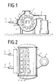
- FIG. 1 shows, a microwave source 2, a waveguide 3 and a horn antenna 4 are mounted axially on one side of the chamber on a cylindrical and horizontally arranged vacuum chamber 1, and a distributor box 5 and a high vacuum pump 6 are connected on the opposite side of the chamber.
- An evaporator bank 7 is fastened centrally and axially in the chamber 1.
- a hollow cylindrical rotary cage 8 is arranged coaxially around this evaporator bank 7, which rotary cage 8 is to be coated Receives substrates 9, 9 ', 9'', ... on its circumference and moves through the plasma 10 generated in a stationary manner in the vacuum chamber 1.
- the distribution box 5 is connected to the center of the longitudinal side of the vacuum chamber 1 for the spatial distribution of the pumping speed of the high vacuum pump 6.
- the substrates 9, 9 ', 9' ', ... to be coated are arranged on the circumference and over the entire length of the rotary cage (FIG. 2).
- the larger opening of the horn antenna 4 is closed with a quartz window 11, to which the magnet systems 12, 12 'are connected.
- the horn antenna 4 is aligned perpendicular to the surface of the rotary cage 8, on which the substrates 9, 9 ', 9' ', ... are attached ( Figure 3).
- the microwave source 2 ′′ is arranged on the end face of a vacuum chamber 1 and connected to a microwave waveguide 3 ′′, which in turn is connected to a microwave antenna structure 13 extending in the axial direction of the vacuum chamber 1.
- This antenna 13 is provided with repeating coupling elements 14, 14 ', ...
- An evaporator bank 7 is arranged above and parallel to the microwave structure 13.
- a rotary cage 8 is rotatably supported in the direction of movement A about the imaginary central longitudinal axis of the chamber.
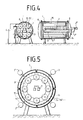
- the holding means 15, 15 ', ... arranged in a planetary manner on the circumference of the cage 8 serve to receive the substrates and perform a further rotary movement in the direction of movement B about an axis of rotation encircling the cage (FIG. 4).
- the magnetrons 2, 2 ', ... are attached to the vacuum chamber 1 in an azimuthally distributed manner, and the microwave antenna structure 16 provided with the coupling elements 14, 14', ... is coaxial with the rotary cage 8 and between it and the chamber wall arranged.
- the angular velocity about the central chamber axis W D and about the planetary axis W d are opposite in the direction of rotation.
- the geometric dimensions required for calculating the angular velocity R, X and b are shown in FIG. 6.
- the gas distribution pipes 17, 17 'for supplying process gas into the vacuum chamber are provided with repeating bores 18, 18', ... and are fastened between the free magnetic poles 19, 19 '.
- a second process gas is introduced into the vacuum chamber with the help of the gas distribution tubes 17 ′′, 17 ′′, which are likewise arranged in the vicinity of the magnetic poles 19, 19 ′ (FIG. 7).
- a microwave ECR plasma source is advantageously used.
- This plasma generator uses the energy from a microwave field (e.g. 2.45 GHz or 900 MHz) to maintain the glow discharge.
- the microwaves are generated in a conventional magnetron and fed into an antenna (e.g. a horn antenna) via a waveguide.
- this antenna also takes on the function of high-vacuum-tight separation of the waveguide area from the Inside the evacuated process chamber to which it is flanged (see Figures 1 and 2).
- the antenna On the vacuum side, the antenna is framed by an annular magnetic yoke, which is equipped with permanent magnets.
- This magnet system creates a self-contained tunnel-shaped magnetic field. This magnetic field is dimensioned such that it fulfills the electrocyclotron resonance condition for the microwave frequency used in a certain area between the free pole faces of the magnets.
- the resonance effect amplifies the energy transfer from the microwave field to the electrons contained in the plasma very efficiently.
- the result is an extremely high reactivity of the heavy particles compared to DC or RF-operated plasmas.
- the magnetic field In addition to the resonance effect generated in the magnetic field, the magnetic field also reduces losses due to diffusion of the charge carriers (containment) and, in the present case, finally produces an equalization of the discharge in the direction of the longitudinal axis of the magnetic yoke as a result of drift movements which it forces on the charge carriers.
- the surfaces of the magnet system exposed to the plasma are advantageously equipped with an easily removable, heatable sign that can be cleaned outside the system at longer intervals and just as easily reassembled.
- the antenna structure through which the long plasma zone is supplied with microwave energy, can be designed as a horn antenna (see FIG. 3), through which the microwave field emerging from the waveguide is expanded in the longitudinal direction of the magnet system.
- the larger opening of the horn antenna is closed with a quartz window, which serves as a microwave-permeable vacuum seal for the recipient.
- this device is outstandingly suitable as a plasma source for the coating and treatment of substrates with complicated three-dimensional surfaces.
- Figures 1, 4 and 5 show three different installation options for the microwave plasma source described in coating systems that have a cylindrical process chamber in which a rotary cage with planetary gear is used for the parts to be coated.
- the plasma source can be inserted in the axial direction, parallel to the longitudinal axis of the chamber, as shown in FIGS. 1 and 4, or azimuthally, as shown in FIG. 5, in the outer jacket of the cylindrical base body of the process chamber. These two versions are also suitable for in-line systems.
- the microwave transmitter can be operated continuously as well as pulsed. Pulsed operation has proven to be advantageous for the processes described below.
- the plasma OFF times take place in particular a desired gas exchange takes place at aerodynamically unfavorable locations in the process chamber and at aerodynamically unfavorable locations of complicatedly shaped three-dimensional substrates, which causes an equalization of layer quality and rate distribution.
- the angular velocities and phases of the planetary movement have to be coordinated in a certain way in the case of the plasma source placed in the axial direction in the outer jacket in order to achieve optimal coating results.
- the following must then apply: With The definition of the quantities used in the expression can be seen in FIG. 6.
- the phase of the rotation of the planets about their own axis is determined by the condition that the surface of the projection of the inner surface to be coated on the concave substrates a plane perpendicular to the coating direction is maximal at the moment of its greatest approach to the coating source.
- the plasma source can be arranged along the geometric axis of symmetry of the cylindrical body of the process chamber (see FIG. 4).
- the coating process described here can also be carried out in an in-line system in which the substrate holders do not necessarily execute a rotational movement about an axis common to them, but are continuously driven through the various chambers in the longitudinal direction of the system by means of a linear drive.
- the plasma source in turn is arranged so that its longitudinal axis is at right angles to the direction of substrate movement.
- Another important advantage of the invention is the arrangement of the gas distribution pipes. It has been found that the arrangement of the gas distribution pipes shown in FIG. 7 provided the best protective layers with high process reliability: the gas distribution pipes, which feed the silicon and carbon-containing gas used to the process, are mounted between the free magnetic poles. If a second gas, e.g. B. oxygen, used in addition to the first, so this can also be let near the yoke in the process chamber.
- a second gas e.g. B. oxygen
- organosilicon compounds used for the protection and precoating processes such a low vapor pressure at room temperature that, in order to ensure the mass flows required for the large-area coating process, they have to be warmed up to typically 70 to 80 ° C. and evaporated (or gasified) at these temperatures in a suitable evaporator. For this reason, all monomer lines that connect to the evaporator downstream must be kept at this temperature by means of suitable heating. In order to make the coating more uniform, the monomer can also be introduced into the process chamber through heated gas distribution pipes.
- the suction power for easily condensable monomers / process gases such as.
- process gases such as.
- trifluoromethane or hexamethyldisiloxane can be selectively varied in a large range without the suction power for process gases with low dew point changing significantly.
- A900H suction power for HMDSO between 300 and 4200 l / s with an O2 pumping speed of about 2000 l / s.
- the suction power is regulated by the temperature of the cold surface and / or by an upstream valve.
- This arrangement enables the process gas / monomer mixtures and the gas / monomer-specific residence times of the process gases / monomers in the process chamber to be varied, and thus the layer composition and layer properties to be varied over a wide range.
- the high vacuum pump is flanged to the process chamber so that the spatial distribution of the pumping speed is homogeneous in the direction of the longitudinal axis of the plasma generator.
- This is the purpose of the box shown in Figure 1, which connects the pump to the process chamber.
- the basic requirements for an equally homogeneous coating are created.
- this homogeneity is, however, sensitively disturbed by these substrates. This is the more pronounced the higher the pressure during the coating process, ie the more viscous the flow conditions, in particular in the coating zone.
- With the microwave ECR plasma source used particularly low process pressures in the range from 1 x 10 ⁇ 4 to 1 x 10 ⁇ 2 mbar are now accessible, for which the flow between coating source and substrates can become almost molecular.
- an RF or mf or a DC bias supply is integrated into the system, which imparts positive potential (bias) to the substrate surfaces via the cage insulated against ground. This enables ion-assisted deposition of particularly dense and hard layers.
- the metallization process can also be used to produce a conductive surface for dielectric substrates, which at the same time makes electrical contact with the rotary cage. This makes ion-assisted deposition possible even with dielectric substrate materials.
- a heater built into the lock-in chamber serves for the purpose of compacting and hardening the depositing layer, with which the temperature of sufficiently heat-resistant substrates can be increased even during lock conditioning.
- a holding heater is installed in the process chamber, which stabilizes the substrate temperature during the coating process. It is also intended that the walls and internals of the process chamber also heat up. Because the consequence is that the layers that are deposited there adhere particularly well and only become after a significantly longer operating time of the system, detach it from its base. The process chamber heating thus extends the time interval between two cleaning cycles and thus the productivity of the entire system.
Landscapes
- Chemical & Material Sciences (AREA)
- Engineering & Computer Science (AREA)
- General Chemical & Material Sciences (AREA)
- Chemical Kinetics & Catalysis (AREA)
- Materials Engineering (AREA)
- Mechanical Engineering (AREA)
- Metallurgy (AREA)
- Organic Chemistry (AREA)
- Physics & Mathematics (AREA)
- Plasma & Fusion (AREA)
- Chemical Vapour Deposition (AREA)
Abstract
Description
Die Erfindung betrifft ein Verfahren und eine Vorrichtung zur Herstellung von Schichten auf der Oberfläche von Werkstücken, vorzugsweise von aus Kunststoffen gebildeten Scheinwerfer-Reflektoreinsätzen, in einer als Batchanlage zu betreibenden Vakuumkammer mit einem PCVD-Beschichtungsverfahren, wobei eine Mikrowellen-ECR-Plasmabeschichtungsquelle eingesetzt wird und die zu beschichtenden Vorderflächenspiegel an einem in der Vakuumkammer befindlichen Drehkäfig befestigt sind, der mit einer frequenz- und phasenabgestimmten Planetenbewegung an der Beschichtungsquelle vorbeigeführt wird.The invention relates to a method and a device for the production of layers on the surface of workpieces, preferably headlight reflector inserts formed from plastics, in a vacuum chamber to be operated as a batch system with a PCVD coating method, a microwave ECR plasma coating source being used and the front surface mirrors to be coated are fastened to a rotary cage located in the vacuum chamber, which is guided past the coating source with a frequency and phase-coordinated planetary movement.
Bekannt ist eine Einrichtung zum Herstellen eines Plasmas und zur Behandlung von Substraten darin (P 37 05 666.2), in der mit Hilfe einer Mikrowellen-ECR-Plasmaquelle ein Beschichtungsprozeß von beispielsweise bandförmigem Substrat durchgeführt wird.A device for producing a plasma and for treating substrates therein is known (P 37 05 666.2), in which a coating process of, for example, a strip-shaped substrate is carried out with the aid of a microwave ECR plasma source.
Weiterhin ist ein Verfahren und eine Vorrichtung zur Herstellung einer korrosionsfesten Schicht auf der Oberfläche von mit Lack überzogenen Werkstücken bekannt (DE 37 31 686), bei dem in einer Vakuumkammer mit Hilfe einer Glimmkathode und einem Verdampfer ein Schichtsystem auf die Werkstücke aufgebracht wird.Furthermore, a method and a device for producing a corrosion-resistant layer on the surface of workpieces coated with lacquer is known (DE 37 31 686), in which a layer system is applied to the workpieces in a vacuum chamber with the aid of a glow cathode and an evaporator.
Bei diesem vorbekannten Verfahren bestehen die für den Korrosionsschutz geeigneten Schichten aus elektrisch nicht bzw. äußerst schlecht leitendem Material. Oberhalb einer Dicke von etwa 100 bis 200 nm sind diese Schichten gute Isolatoren. Beim Betrieb der herkömmlichen Anlagen zur Schutzbeschichtung von Kfz-Reflektoren, die mit Gleichspannung betrieben werden, bilden sich während des Beschichtungsprozesses insbesondere auf den Elektroden stetig wachsende Schichten, die innerhalb kurzer Zeit die für die elektrische Leitfähigkeit kritische Dicke erreicht haben und isolierend werden. Sie verhindern damit die Aufrechterhaltung der mit Gleichspannung betriebenen Glimmentladung. Zur wiederaufbereitenden Reinigung der Elektroden muß die Prozeßkammer nach jeder Charge, also in kurzen Abständen geflutet werden. Erfahrungsgemäß ist das Fluten einer Prozeßkammer immer mit einer enormen Partikelgeneration begleitet, die jedesmal eine aufwendige Reinigung der gesamten Prozeßkammer notwendig macht. Der Betrieb einer Gleichspannungs-(DC-)PCVD-Anlage ist daher sehr personal- und kostenintensiv. Die DC-PCVD-Technik ist aufgrund des Prozeßdruckbereiches von einigen Millibar und des dadurch bedingten Partikelanteils nicht in-line-fähig.In this known method, the layers suitable for corrosion protection consist of electrically non-conductive or extremely poorly conductive material. Above a thickness of approximately 100 to 200 nm, these layers are good insulators. When the conventional systems for the protective coating of motor vehicle reflectors, which are operated with direct voltage, are operated, continuously growing layers form on the electrodes, which within a short time have reached the critical thickness for electrical conductivity and become insulating. This will prevent the glow discharge operated with DC voltage from being maintained. To reprocess the electrodes, the process chamber must be flooded after every batch, i.e. at short intervals. Experience has shown that the flooding of a process chamber is always accompanied by an enormous generation of particles, which means that the entire process chamber has to be cleaned each time. The operation of a direct voltage (DC) PCVD system is therefore very personnel and cost intensive. Due to the process pressure range of a few millibars and the resulting particle content, the DC-PCVD technology is not in-line capable.
Des weiteren wird aus dem oben Gesagten ohne weiteres auch klar, daß eine DC-Plasmapolymerisationsanlage keine Schichten einer größeren Dicke als etwa 100 nm zuverlässig herstellen kann.Furthermore, it is also readily apparent from the above that a DC plasma polymerization system cannot reliably produce layers with a thickness greater than about 100 nm.
Die bei der DC-PCVD eingesetzte DC-Glimmentladung wird im Druckbereich von einigen Millibar betrieben. Die Strömungsverhältnisse sind in diesem Druckbereich in jedem Falle hochviskos, turbulent und daher weder über-schau- noch beherrschbar. Unter diesem Verhältnissen eine gleichmäßige Schichtdickenverteilung zu schaffen ist praktisch nicht möglich.The DC glow discharge used in the DC-PCVD is operated in the pressure range of a few millibars. The flow conditions in this pressure range are always highly viscous, turbulent and therefore neither manageable nor manageable. It is practically impossible to create a uniform layer thickness distribution under these conditions.
Ein kaum zu überschätzender Nachteil des herkömmlichen Verfahrens ist auch, daß Reflektorgrundkörper, deren Vorlackierung ein Alter von einigen Stunden besitzt, nicht mehr zufriedenstellend haftfest aluminisiert und schutzbeschichtet werden können; die Reflektorgrundkörper müssen kurz nach ihrer Vorlackierung weiterverarbeitet werden. Dies ist eine erheblicher Nachteil des Beschichtungsverfahrens, da eine Zwischenlagerung zwischen den Produktionsschritten des Vorlackierens und den Vakuumbeschichtungen nicht möglich und demzufolge beide Prozesse innerhalb des Produktionsablaufes sehr zeitkritisch werden.Another disadvantage of the conventional method that can hardly be overestimated is that reflector base bodies, the pre-coating of which is a few hours old, can no longer be satisfactorily aluminized and protective-coated; the reflector base bodies must be processed shortly after they have been primed. This is a considerable disadvantage of the coating process, since intermediate storage between the pre-painting production steps and the vacuum coatings is not possible, and consequently both processes within the production process become very time-critical.
Ziel der vorliegenden Erfindung ist es, Vorrichtungen und Verfahren zu entwickeln, die es gestatten, im kontinuierlichen, kostengünstigen Betrieb dielektrische Schichten beliebiger Dicke abzuscheiden. Ein weiteres Ziel der Erfindung ist es, die mit dem DC-PCVD-Verfahren hergestellten Schichten hinsichtlich ihrer Korrosions- und Wischfestigkeit weiter zu verbessern.The aim of the present invention is to develop devices and methods which allow continuous, inexpensive operation to deposit dielectric layers of any thickness. Another object of the invention is to further improve the layers produced with the DC-PCVD method with regard to their resistance to corrosion and wiping.
Diese Aufgabe wird erfindungsgemäß gelöst durch den Einsatz einer Mikrowellen-ECR-Plasmabeschichtungsquelle, wobei die zu beschichtenten Vorderflächenspiegel an einem in der Vakuumkammer befindlichen Drehkäfig befestigt sind, der mit einer frequenz- und phasenabgestimmten Planetenbewegung an einer Beschichtungsquelle vorbeiführbar ist und dadurch, daß die Beschichtungsprozesse, wie beispielsweise die Metallisierung der Substratoberfläche durch eine aufzubringende Aluminiumschicht, in der Vakuumkammer unter Plasma und bei Drücken unterhalb von 2 x 10⁻² mbar durchführbar sind.This object is achieved according to the invention by the use of a microwave ECR plasma coating source, the front surface mirrors to be coated being fastened to a rotary cage located in the vacuum chamber, which can be guided past a coating source with a frequency- and phase-coordinated planetary movement and because the coating processes, such as the metallization of the substrate surface by an aluminum layer to be applied, in the vacuum chamber under plasma and at pressures below 2 x 10⁻² mbar can be carried out.
Weitere Einzelheiten und Merkmale sind in den Patentansprüchen näher gekennzeichnet.Further details and features are characterized in more detail in the claims.
Die Erfindung läßt die verschiedensten Ausführungsmöglichkeiten zu; eine davon ist in den anhängenden Zeichnungen näher dargestellt, und zwar zeigen:
- Fig. 1
- eine Vorrichtung zur Beschichtung von Vorderflächenspiegeln - bestehend im wesentlichen aus einer Mikrowellenquelle, einer Vakuumkammer mit Einbauten und einem Vakuumpumpstand - im Schnitt,
- Fig. 2
- eine Vorrichtung gemäß
Figur 1 in der Draufsicht, - Fig. 3
- eine Hornantenne und ein Ausschnitt aus einem Drehkäfig in perspektivischer Sicht,
- Fig. 4
- eine Vorrichtung gemäß
Figur 1 mit in axialer Richtung angeordneter Plasmaquelle im Quer- und im Längsschnitt, - Fig. 5
- eine Vorrichtung gemäß
Figur 1 mit in azimutaler Richtung angeordneten Plasmaquellen im Schnitt, jedoch ohne Vakuumpumpstand, - Fig. 6
- ein Hilfsbild zur Erläuterung der zur Berechnung der Winkelgeschwindigkeiten um die zentrale Achse und die Planeteneigenachse des Drehkäfigs notwendigen Größen und
- Fig. 7
- eine Anordnung der Gasverteilungsrohre in der Vakuumkammer im Schnitt.
- Fig. 1
- a device for coating front surface mirrors - consisting essentially of a microwave source, a vacuum chamber with internals and a vacuum pumping station - in section,
- Fig. 2
- 2 shows a device according to FIG. 1 in plan view,
- Fig. 3
- a horn antenna and a section of a rotary cage in perspective,
- Fig. 4
- 2 shows a device according to FIG. 1 with a plasma source arranged in the axial direction in cross-section and in longitudinal section,
- Fig. 5
- 2 shows a device according to FIG. 1 with plasma sources arranged in the azimuthal direction on average, but without a vacuum pumping station,
- Fig. 6
- an auxiliary picture for explaining the sizes and necessary for calculating the angular velocities around the central axis and the planetary axis of the rotary cage
- Fig. 7
- an arrangement of the gas distribution pipes in the vacuum chamber in section.
Wie Figur 1 zeigt, sind an einer zylindrischen und horizontal angeordneten Vakuumkammer 1 eine Mikrowellenquelle 2, ein Hohlleiter 3 und eine Hornantenne 4 axial auf einer Seite der Kammer angebaut und ein Verteilerkasten 5 sowie eine Hochvakuumpumpe 6 an der gegenüberliegenden Seite der Kammer angeschlossen. In der Kammer 1 ist zentral und in axialer Richtung eine Verdampferbank 7 befestigt.As FIG. 1 shows, a
Koaxial um diese Verdampferbank 7 ist ein hohlzylindrischer Drehkäfig 8 angeordnet, der die zu beschichtenden Substrate 9, 9', 9'', ... auf seinem Umfang aufnimmt und durch das in der Vakuumkammer 1 ortsfest erzeugte Plasma 10 hindurchbewegt.A hollow cylindrical
An der hier gezeigten Vakuumkammer 1 sind je 2 Stück Mikrowellenquellen 2, 2' und Hohlleiter 3, 3' vorgesehen. Der Verteilerkasten 5 ist zur räumlichen Verteilung des Saugvermögens der Hochvakuumpumpe 6 an der Längsseite der Vakuumkammer 1 mittig angeschlossen. Die zu beschichtenden Substrate 9, 9', 9'', ... sind am Umfang und über die gesamte Länge des Drehkäfigs angeordnet (Figur 2).Two pieces of
Die größere Öffnung der Hornantenne 4 ist mit einem Quarzfenster 11 abgeschlossen, an das sich die Magnetsysteme 12, 12' anschließen. Die Hornantenne 4 ist lotrecht auf die Oberfläche des Drehkäfigs 8 ausgerichtet, auf der die Substrate 9, 9', 9'', ... befestigt sind (Figur 3).The larger opening of the
Die Mikrowellenquelle 2'' ist stirnseitig an einer Vakuumkammer 1 angeordnet und mit einem Mikrowellenhohlleiter 3'' verbunden, der wiederum an eine sich in axialer Richtung der Vakuumkammer 1 erstreckenden Mikrowellen-Antennenstruktur 13 angeschlossen ist. Diese Antenne 13 ist mit sich wiederholenden Koppelelementen 14, 14', ... versehen.The
Oberhalb und parallel der Mikrowellenstruktur 13 ist eine Verdampferbank 7 angeordnet. Ein Drehkäfig 8 ist um die gedachte zentrale Kammerlängsachse in Bewegungsrichtung A drehbar gelagert. Die am Umfang des Käfigs 8 planetenartig angeordneten Haltemittel 15, 15', ... dienen zur Aufnahme der Substrate und führen eine weitere Drehbewegung in Bewegungsrichtung B um eine mit dem Käfig umlaufende Drehachse aus (Figur 4).An
In Figur 5 sind die Magnetrons 2, 2', ... azimutal verteilt an der Vakuumkammer 1 befestigt und die mit den Koppelelementen 14, 14', ... versehene Mikrowellen-Antennenstruktur 16 ist koaxial zum Drehkäfig 8 und zwischen diesem und der Kammerwand angeordnet.In FIG. 5, the
Die Winkelgeschwindigkeit um die zentrale Kammerachse WD und um die Planeteneigenachse Wd sind im Drehsinn gegenläufig. Die notwendigen geometrischen Abmessungen zur Berechnung der Winkelgeschwindigkeit R, X und b sind in Figur 6 gezeigt.The angular velocity about the central chamber axis W D and about the planetary axis W d are opposite in the direction of rotation. The geometric dimensions required for calculating the angular velocity R, X and b are shown in FIG. 6.
Die Gasverteilungsrohre 17, 17' zur Zuführung von Prozeßgas in die Vakuumkammer sind mit sich wiederholenden Bohrungen 18, 18', ... versehen und zwischen den freien Magnetpolen 19, 19' befestigt. Ein zweites Prozeßgas wird mit Hilfe der ebenfalls in Nähe der Magnetpole 19, 19' angeordneten Gasverteilungsrohre 17'', 17''' in die Vakuumkammer eingeleitet (Figur 7).The
Es wird mit Vorteil eine Mikrowellen-ECR-Plasmaquelle eingesetzt. Mit diesem Plasmagenerator wird die Energie aus einem Mikrowellenfeld (z. B. 2,45 GHz oder 900 MHz) verwendet, um die Glimmentladung aufrechtzuerhalten. Die Mikrowellen werden in einem konventionellen Magnetron erzeugt und über einen Hohlleiter in eine Antenne (z. B. eine Hornantenne) eingespeist. Diese Antenne übernimmt gleichzeitig auch die Funktion der hochvakuumdichten Trennung des Hohlleiterbereiches vom Inneren der evakuierten Prozeßkammer, an die sie angeflanscht ist (siehe Figuren 1 und 2).A microwave ECR plasma source is advantageously used. This plasma generator uses the energy from a microwave field (e.g. 2.45 GHz or 900 MHz) to maintain the glow discharge. The microwaves are generated in a conventional magnetron and fed into an antenna (e.g. a horn antenna) via a waveguide. At the same time, this antenna also takes on the function of high-vacuum-tight separation of the waveguide area from the Inside the evacuated process chamber to which it is flanged (see Figures 1 and 2).
Vakuumseitig wird die Antenne von einem ringförmigen Magnetjoch umrahmt, das mit Permanentmagneten bestückt ist. Dieses Magnetsystem erzeugt ein in sich geschlossenes tunnelförmiges Magnetfeld. Dieses Magnetfeld ist so dimensioniert, daß es in einem gewissen Bereich zwischen den freien Polflächen der Magnete die Elektrozyklotron-Resonanzbedingung für die verwendete Mikrowellenfrequenz erfüllt.On the vacuum side, the antenna is framed by an annular magnetic yoke, which is equipped with permanent magnets. This magnet system creates a self-contained tunnel-shaped magnetic field. This magnetic field is dimensioned such that it fulfills the electrocyclotron resonance condition for the microwave frequency used in a certain area between the free pole faces of the magnets.
Durch den Resonanzeffekt wird der Energieübertrag vom Mikrowellenfeld zu den im Plasma enthaltenen Elektronen sehr effizient verstärkt. Die Folge ist eine im Vergleich zu DC- oder rf-betriebenen Plasmen äußerst hohe Reaktivität der Schwerteilchen.The resonance effect amplifies the energy transfer from the microwave field to the electrons contained in the plasma very efficiently. The result is an extremely high reactivity of the heavy particles compared to DC or RF-operated plasmas.
Abgesehen von dem im Magnetfeld erzeugten Resonanzeffekt, vermindert das Magnetfeld auch noch Verluste durch Diffusion der Ladungsträger (containment) und erzeugt im vorliegenden Falle schließlich infolge von Driftbewegungen, die es den Ladungsträgern aufzwingt, eine Vergleichmäßigung der Entladung in Richtung der Längsachse des Magnetjoches.In addition to the resonance effect generated in the magnetic field, the magnetic field also reduces losses due to diffusion of the charge carriers (containment) and, in the present case, finally produces an equalization of the discharge in the direction of the longitudinal axis of the magnetic yoke as a result of drift movements which it forces on the charge carriers.
Die dem Plasma ausgesetzten Flächen des Magnetsystems sind vorteilhaft ausgerüstet mit einem einfach abnehmbaren, heizbaren Schild, das in größeren zeitlichen Abständen außerhalb der Anlage gereinigt und ebenso leicht wieder montiert werden kann.The surfaces of the magnet system exposed to the plasma are advantageously equipped with an easily removable, heatable sign that can be cleaned outside the system at longer intervals and just as easily reassembled.
Die Antennenstruktur, durch die die Versorgung der langen Plasmazone mit Mikrowellenenergie erfolgt, kann als Hornantenne ausgeführt werden (siehe Figur 3), durch die das aus dem Hohlleiter austretende Mikrowellenfeld in die Längsrichtung des Magnetsystems aufgeweitet wird. Die größere Öffnung der Hornantenne ist mit einem Quarzfenster abgeschlossen, das als mikrowellendurchlässige Vakuumdichtung für den Rezipienten dient.The antenna structure, through which the long plasma zone is supplied with microwave energy, can be designed as a horn antenna (see FIG. 3), through which the microwave field emerging from the waveguide is expanded in the longitudinal direction of the magnet system. The larger opening of the horn antenna is closed with a quartz window, which serves as a microwave-permeable vacuum seal for the recipient.
Mit Vorteil stellte sich heraus, daß diese Vorrichtung hervorragend als Plasmaquelle für die Beschichtung und Behandlung von Substraten mit kompliziert dreidimensional geformten Oberflächen geeignet ist.It was found to be advantageous that this device is outstandingly suitable as a plasma source for the coating and treatment of substrates with complicated three-dimensional surfaces.
Figuren 1, 4 und 5 zeigen drei verschiedene Einbaumöglichkeiten für die beschriebene Mikrowellenplasmaquelle in Beschichtungsanlagen, die eine zylindrisch geformte Prozeßkammer besitzen, in der ein Drehkäfig mit Planetengetriebe für die zu beschichtenden Teile eingesetzt ist.Figures 1, 4 and 5 show three different installation options for the microwave plasma source described in coating systems that have a cylindrical process chamber in which a rotary cage with planetary gear is used for the parts to be coated.
Die Plasmaquelle kann in axialer Richtung, parallel zur Kammerlängsachse, wie Figuren 1 und 4 zeigen, oder azimutal, wie Figur 5 zeigt, in den Außenmantel des zylindrischen Grundkörpers der Prozeßkammer eingefügt werden. Diese beiden Versionen sind auch für In-line-Anlagen geeignet.The plasma source can be inserted in the axial direction, parallel to the longitudinal axis of the chamber, as shown in FIGS. 1 and 4, or azimuthally, as shown in FIG. 5, in the outer jacket of the cylindrical base body of the process chamber. These two versions are also suitable for in-line systems.
Der Mikrowellensender kann sowohl kontinuierlich als auch gepulst betrieben werden. Als vorteilhaft für die unten beschriebenen Prozesse hat sich der gepulste Betrieb erwiesen. In den Plasma-AUS-Zeiten findet insbesondere an strömungstechnisch ungünstigen Stellen in der Prozeßkammer und an strömungstechnisch ungünstigen Stellen kompliziert geformter dreidimensionaler Substrate ein gewünschter Gasaustausch statt, der eine Vergleichmäßigung von Schichtqualität und Ratenverteilung bewirkt.The microwave transmitter can be operated continuously as well as pulsed. Pulsed operation has proven to be advantageous for the processes described below. The plasma OFF times take place in particular a desired gas exchange takes place at aerodynamically unfavorable locations in the process chamber and at aerodynamically unfavorable locations of complicatedly shaped three-dimensional substrates, which causes an equalization of layer quality and rate distribution.
Soll die Innenfläche von konkav geformten Substraten beschichtet werden, so müssen im Fall deR in axialer Richtung in den Außenmantel gesetzten Plasmaquelle die Winkelgeschwindigkeiten und Phasen der Planetenbewegung in bestimmter Weise aufeinander abgestimmt werden, um optimale Beschichtungsergebnisse zu erzielen. Für die Winkelgeschwindigkeit um die zentrale Achse ωD und Winkelgeschwindigkeit ωd um die Planeteneigenachse, gemessen relativ zum mit ωD rotierenden Käfigsystem muß dann gelten:
mit
Die Definition der in dem Ausdruck verwendeten Größen ist aus Figur 6 ersichtlich. Die Phasen der Rotation der Planeten um ihre eigene Achse ist durch die Bedingung festgelegt, daß die Fläche der Projektion der zu beschichtenden Innenfläche der konkaven Substrate auf eine Ebene senkrecht zur Beschichtungsrichtung im Augenblick ihrer größten Annäherung an die Beschichtungsquelle maximal ist.If the inner surface of concavely shaped substrates is to be coated, the angular velocities and phases of the planetary movement have to be coordinated in a certain way in the case of the plasma source placed in the axial direction in the outer jacket in order to achieve optimal coating results. For the angular velocity around the central axis ω D and angular velocity ω d about the planetary axis, measured relative to the cage system rotating with ω D , the following must then apply:
With
The definition of the quantities used in the expression can be seen in FIG. 6. The phase of the rotation of the planets about their own axis is determined by the condition that the surface of the projection of the inner surface to be coated on the concave substrates a plane perpendicular to the coating direction is maximal at the moment of its greatest approach to the coating source.
Handelt es sich um eine Batchanlage ohne Ausschleuskammer, kann die Plasmaquelle entlang der geometrischen Symmetrieachse des zylindrischen Prozeßkammergrundkörpers angeordnet werden (siehe Figur 4).If it is a batch system without a discharge chamber, the plasma source can be arranged along the geometric axis of symmetry of the cylindrical body of the process chamber (see FIG. 4).
Der hier beschriebene Beschichtungsprozeß ist auch in einer In-line-Anlage durchführbar, in der die Substrathalter nicht zwangsläufig eine Rotationsbewegung um eine ihnen gemeinsame Achse ausführen, sondern mittels eines Linearantriebes kontinuierlich in Anlagenlängsrichtung durch die verschiedenen Kammern gefahren werden. Die Plasmaquelle ihrerseits ist so angeordnet, daß ihre Längsachse im rechten Winkel zur Substratbewegungsrichtung verläuft.The coating process described here can also be carried out in an in-line system in which the substrate holders do not necessarily execute a rotational movement about an axis common to them, but are continuously driven through the various chambers in the longitudinal direction of the system by means of a linear drive. The plasma source in turn is arranged so that its longitudinal axis is at right angles to the direction of substrate movement.
Ein weiterer wesentlicher Vorteil der Erfindung ist die Anordnung der Gasverteilungsrohre. Es hat sich erwiesen, daß die in Figur 7 gezeigte Anordnung der Gasverteilungsrohre bei hoher Prozeßsicherheit die besten Schutzschichten erbrachte: Die Gasverteilungsrohre, die das jeweils verwendete, Silizium und Kohlenstoff enthaltende Gas dem Prozeß zuführen, werden zwischen den freien Magnetpolen montiert. Wird ein zweites Gas, z. B. Sauerstoff, zusätzlich zum ersten eingesetzt, so kann dies ebenfalls in Jochnähe in die Prozeßkammer eingelassen werden.Another important advantage of the invention is the arrangement of the gas distribution pipes. It has been found that the arrangement of the gas distribution pipes shown in FIG. 7 provided the best protective layers with high process reliability: the gas distribution pipes, which feed the silicon and carbon-containing gas used to the process, are mounted between the free magnetic poles. If a second gas, e.g. B. oxygen, used in addition to the first, so this can also be let near the yoke in the process chamber.
Einige der für die Schutz- und die Vorbeschichtungsprozesse verwendeten Organosilizium-Verbindungen besitzen bei Raumtemperatur einen so niedrigen Dampfdruck, daß sie, um die für den Großflächenbeschichtungsprozeß notwendigen Massenflüsse sicherzustellen, auf typisch 70 bis 80 °C aufgewärmt und bei diesen Temperaturen in einem geeigneten Verdampfer verdampft (bzw. vergast) werden müssen. Daher sind alle Monomerleitungen, die sich stromabwärts an den Verdampfer anschließen, mittels einer geeigneten Heizung auf eben dieser Temperatur zu halten. Zwecks Vergleichmäßigung der Beschichtung kann das Monomer durch ebenfalls geheizte Gasverteilungsrohre in die Prozeßkammer eingelassen werden.Have some of the organosilicon compounds used for the protection and precoating processes such a low vapor pressure at room temperature that, in order to ensure the mass flows required for the large-area coating process, they have to be warmed up to typically 70 to 80 ° C. and evaporated (or gasified) at these temperatures in a suitable evaporator. For this reason, all monomer lines that connect to the evaporator downstream must be kept at this temperature by means of suitable heating. In order to make the coating more uniform, the monomer can also be introduced into the process chamber through heated gas distribution pipes.
Mittels einer Kaltfläche kann die Saugleistung für leicht kondensierbare Monomere/Prozeßgase, wie z. B. Trifluormethan oder Hexamethyldisiloxan, in einem goßen Bereich selektiv variiert werden, ohne daß sich die Saugleistung für Prozeßgase mit niedrigem Taupunkt nennenswert verändert. (Beispiel: A900H, Saugleistung für HMDSO zwischen 300 und 4200 l/s bei einem O₂-Saugvermögen von etwa 2000 l/s.) Die Saugleistung wird über die Temperatur der Kaltfläche und/oder durch ein vorgeschaltetes Ventil reguliert.Using a cold surface, the suction power for easily condensable monomers / process gases, such as. As trifluoromethane or hexamethyldisiloxane, can be selectively varied in a large range without the suction power for process gases with low dew point changing significantly. (Example: A900H, suction power for HMDSO between 300 and 4200 l / s with an O₂ pumping speed of about 2000 l / s.) The suction power is regulated by the temperature of the cold surface and / or by an upstream valve.
Diese Anordnung ermöglicht eine Variation der Prozeßgas/Monomermischungen und der gas-/monomerspezifischen Verweilzeiten der Prozeßgase/Monomere in der Prozeßkammer und damit eine Variation der Schichtzusammensetzung und Schichteigenschaften in einem großen Bereich.This arrangement enables the process gas / monomer mixtures and the gas / monomer-specific residence times of the process gases / monomers in the process chamber to be varied, and thus the layer composition and layer properties to be varied over a wide range.
Die Hochvakuumpumpe ist so an die Prozeßkammer angeflanscht, daß die räumliche Verteilung des Saugvermögens in Richtung der Längsachse des Plasmagenerators homogen ist. Das ist der Zweck des in Figur 1 gezeigten Kastens, der die Pumpe mit der Prozeßkammer verbindet. In Verbindung mit homogener Gasversorgung durch die Gasverteilungsrohre und homogener Plasmaerzeugung sind damit die Grundvoraussetzungen für eine ebenso homogene Beschichtung geschaffen. Insbesondere bei der Beschichtung von Formteilen, die zudem noch zusammen mit den immer notwendigen Substrathaltern in einer Planetenbewegung durch die Beschichtungszone hindurchgeführt werden, wird diese Homogenität von eben diesen Substraten jedoch unter Umständen empfindlich gestört. Und zwar ist dies um so ausgeprägter der Fall, je höher der Druck während des Beschichtungsprozesses ist, d. h. je viskoser die Strömungsverhältnisse insbesondere in der Beschichtungszone sind. Mit der eingesetzten Mikrowellen-ECR-Plasmaquelle sind nun besonders niedrige Prozeßdrücke im Bereich von 1 x 10⁻⁴ bis 1 x 10⁻² mbar zugänglich, für die die Strömung zwischen Beschichtungsquelle und Substraten nahezu molekular werden kann.The high vacuum pump is flanged to the process chamber so that the spatial distribution of the pumping speed is homogeneous in the direction of the longitudinal axis of the plasma generator. This is the purpose of the box shown in Figure 1, which connects the pump to the process chamber. In conjunction with a homogeneous gas supply through the gas distribution pipes and homogeneous plasma generation, the basic requirements for an equally homogeneous coating are created. In particular when coating molded parts, which are also passed through the coating zone together with the substrate holders that are always necessary in a planetary motion, this homogeneity is, however, sensitively disturbed by these substrates. This is the more pronounced the higher the pressure during the coating process, ie the more viscous the flow conditions, in particular in the coating zone. With the microwave ECR plasma source used, particularly low process pressures in the range from 1 x 10⁻⁴ to 1 x 10⁻² mbar are now accessible, for which the flow between coating source and substrates can become almost molecular.
Die Messung zeigte nun, daß die Depositionsrate bei diesen niedrigen Drücken nicht nur noch befriedigend hoch war, sondern daß auch - und zwar ebenfalls bei diesen niedrigen Drücken - die Schichtqualität hervorragend war. Aufgrund der oben erläuterten engen, für die vakuumtechnische Großflächenbeschichtung typischen Randbedingungen ist nicht viel Raum für die Optimierung des Prozesses gewesen; insofern war das gute Ergebnis überraschend. Ebenfalls der Homogenisierung der räumlichen Ratenverteilung auf dreidimensionalen Substraten dient im Fall der Verwendung eines Drehkäfigs die oben schon erwähnte genaue Abstimmung der Phasen und Frequenzen der beiden Rotationsbewegungen, aus denen sich die Planetenbewegung zusammensetzt.The measurement now showed that the deposition rate was not only satisfactorily high at these low pressures, but that the coating quality was also excellent - and also at these low pressures. Because of the narrow boundary conditions explained above, which are typical for large-area vacuum technology coating, there was not much space for optimizing the process; so the good result was surprising. The above-mentioned precise coordination of the phases and frequencies of the two rotational movements, from which the planetary movement is composed, also serves to homogenize the spatial rate distribution on three-dimensional substrates if a rotary cage is used.
In die Anlage integriert ist eine je nach elektrischer Leitfähigkeit der Substratoberfläche rf- bzw. mf- oder eine DC-Biasversorgung, die über den gegen Masse isolierten Käfig den Substratoberflächen positives Potetial (Bias) aufprägt. Damit ist ionenunterstützte Abscheidung von besonders dichten und harten Schichten möglich.Depending on the electrical conductivity of the substrate surface, an RF or mf or a DC bias supply is integrated into the system, which imparts positive potential (bias) to the substrate surfaces via the cage insulated against ground. This enables ion-assisted deposition of particularly dense and hard layers.
Durch den Metallisierungsprozeß kann auch bei dielektrischen Substraten eine leitende Oberfläche erzeugt werden, die gleichzeitig den elektrischen Kontakt zum Drehkäfig herstellt. Damit wird auch bei dielektrischen Substratmaterialien eine ionenunterstützte Abscheidung möglich.The metallization process can also be used to produce a conductive surface for dielectric substrates, which at the same time makes electrical contact with the rotary cage. This makes ion-assisted deposition possible even with dielectric substrate materials.
Dem Zweck der Verdichtung und Härtung der sich abscheidenden Schicht dient eine in die Einschleuskammer eingebaute Heizung, mit der die Temperatur ausreichend hitzebeständiger Substrate schon während der Schleusenkonditionierung gesteigert werden kann. In der Prozeßkammer ist eine Halteheizung installiert, die die Substrattemperatur während des Beschichtungsprozesses stabilisiert. Dabei ist auch beabsichtigt, daß sich die Wände und die Einbauten der Prozeßkammer ebenfalls aufheizen. Denn die Folge ist, daß die sich dort abscheidenden Schichten besonders gut haften und sich erst nach deutlich verlängerter Betriebszeit der Anlage von ihrer Unterlage lösen. Die Prozeßkammerheizung verlängert also das Zeitintervall zwischen zwei Reinigungszyklen und also die Produktivität der Gesamtanlage.A heater built into the lock-in chamber serves for the purpose of compacting and hardening the depositing layer, with which the temperature of sufficiently heat-resistant substrates can be increased even during lock conditioning. A holding heater is installed in the process chamber, which stabilizes the substrate temperature during the coating process. It is also intended that the walls and internals of the process chamber also heat up. Because the consequence is that the layers that are deposited there adhere particularly well and only become after a significantly longer operating time of the system, detach it from its base. The process chamber heating thus extends the time interval between two cleaning cycles and thus the productivity of the entire system.
Das erfindungsgemäße Verfahren ist in die folgenden Verfahrensschritte zu unterteilen:
- 1. Plasmaunterstützte Vorbehandlung der Substratoberfläche bei folgenden Parametern: Zusammensetzung der Gasatmosphäre: Eine (per)fluorierte Kohlenstoffverbindung, z. B. CF₄ bei einem Partialdruck zwischen 0,1 µbar und 1 mbar und Sauerstoff bei einem Partialdruck zwischen 0,25 µbar und 1 mbar; Mikrowellenleistung zwischen 100
W und 1 kW pro 0,5 m Plasmalänge; kein zusätzliches Substratpotential, Saugvermögen zwischen 100 l/s und 2000 l/S/Stickstoff pro 0,5 m Plasmalänge; Abstand der Substratoberflächen zur Plasmaquelle zwischen 2 cm und 1 m.Behandlungsdauer zwischen 10sec und 2 min.
Der Effekt dieser Vorbehandlung ist eine deutlich gesteigerte Haftfestigkeit der nachfolgend aufgebrachten Schicht zur Substratoberfläche. Inwiefern sich diese verbesserte Haftung in einer gesteigerten Korrosionsfestigkeit des Endproduktes auswirkt, wird weiter unten erklärt. - 2. Nichtbeschichtende Plasmavorbehandlungen in einer sauerstoffhaltigen oder/und stickstoffhaltigen Atmosphäre bei einem Prozeßdruck zwischen 2 x 10⁻² mbar und 1 mbar, Mikrowellenleistung zwischen 100
W und 1 kW pro 0,5 m Plasmalänge, Saugvermögen zwischen 100 l/s und 2000 l/s/Sauerstoff, Abstand der Substratoberflächen zur Plasmaquelle zwischen 5 cm und 1 m.Behandlungsdauer zwischen 0,1sec und 10 sec, Prozeßgase z. B. O₂, H₂O, N₂O, NH₃ oder N₂.
Diese Vorbehandlung bewirkt eine Funktionalisierung der Substratoberfläche. Das heißt, auf der Substratoberfläche werden funktionelle Gruppen erzeugt, wie z. B Hydroxyl-, Carbonyl- oder Aminogruppen. Das Ergebnis dieser Oberflächenmodifikation ist eine verbesserte Haftfestigkeit nachfolgender Schichten. - 3. Heizung der Substrate auf die höchste für das gegebene Substratmaterial zulässige Temperatur, jedoch weniger als 300 °C.
- 4. Egalisierungsschicht
Aufbringen einer ca. 1 - 5 µm dicken PCVD-Schicht, die einen rauhe Oberflächen einebnenden Effekt hat. Der Vorteil gegenüber naßchemisch aufgebrachten Lacken ist, daß die PCVD-Schichten hitzebeständig bis 600 °C sein können; aufgrund der langen Prozeßzeit allerdings nur für Substrate mit hoher Wertschöpfung geeignet. - 5. Beschichten der so vorbehandelten oder auch nicht vorbehandelten Oberflächen mit einer Haftvermittlungschicht zum Aluminium bei folgenden Prozeßparametern: Zusammensetzung der Gasatmosphäre:
Eine nur oder hauptsächlich Silizium, Kohlenstoff und Wasserstoff enthaltende Organosilizium-Verbindung, wie z. B. Tetramethylsilan oder Hexamethyldisiloxan, bei einem Partialdruck zwischen 0,1 µbar und 10,0 µbar oder ein Silan, z. B. Disilan, gemischt mit einem Kohlenwasserstoff, z. B. CH₄, C₂H₂, Benzol, oder einer Organosilizium-Verbindung, auch zusammen mit einem sauerstoffhaltigen Gas, wie z. B. N₂O, bei einem Druck des Gasgemisches zwischen 0,1 µbar und 12 µbar; Mikrowellenleistung zwischen 200W und 2 kW pro 0,5 m Plasmalänge, zusätzliche Substratvorspannung <= 100 V, Saugvermögen zwischen 600 l/s und 2000 l/s/Stickstoff und zwischen 300 l/s und 4000 l/s/Hexamethyldisiloxan pro 0,5 m Plasmalänge, Abstand zwischen Plasmaquelle und Substratvorderkante zwischen 2 cm und 20 cm, Bedingungen für die Zusammensetzung der Schicht, bezogen auf Silizium, Kohlenstoff und Sauerstoff: Si: > 20 at%, C < 50 at%, O < 30 at% , Schichtdicke zwischen 20 Å und 800 Å.
Der Sinn dieser Vorbehandlung ist eine weitere Steigerung der Haftfestigkeit der im nächsten Prozeßschritt aufzubringenden Metallschicht auf der Unterlage. Die haftungsvermittelnde Wirkung ist insbes. für die Korrosionsfestigkeit des Schichtsystems von Bedeutung. Gute Haftung verhindert das Eindringen agressiver Medien, ausgehend von Pin-windows im oder mechanischen BeSchädigungen des Schichtsystems, zwischen Aluminiumschicht und die Vorbeschichtung bzw. zwischen Aluminiumschicht und die Substratoberfläche durch Kapillarwirkung. Die dem korrosiven Medium ausgesetzte Aluminiumoberfläche wird somit minimiert. - 6. Metallisierung
Beschichten der so vorbeschichteten Substrate mit einer zwischen 700 A° und 2 µm dicken Aluminiumschicht entweder durch Aufdampfen oder durch Sputtern. Handelt es sich um Substrate mit kompliziert dreidimensional geformten Oberflächen, die auch Hinterschneidungen besitzen können, die ebenfalls beschichtet werden müssen, so ist beim Sputtern ein Sputtergasdruckvon mehr als 6 µbar eines möglichst schweren Edelgases, dessen Preis noch vertretbar ist, nämlich Krypton, zu bevorzugen. - 7. Nichtbeschichtende Plasma-Nachbehandlung der Metallschicht
Oberflächliche Oxidation der Aluminiumschicht mittels Plasma in einer sauerstoffhaltigen Prozeßatmosphäre. Prozeßgase, z. B. Sauerstoff, Wasser oder Stickoxidul, auch zusammen mit anderen Prozeßgasen wie z. B Helium oder Argon,Prozeßdrücke zwischen 0,1 µbar und 1 mbar, Saugvermögen zwischen 300 und 2000 l/S/Sauerstoff pro 0,5 m Plasmalänge, Prozeßzeit ≦ 1 min. Der Prozeß bewirkt eine verbesserte Abrasionsfestigkeit der Aluminiumschicht. - 8. Schutzbeschichtung
- 8.1 Beschichtung der zuvor metallisierten Substrate in einem weiteren PCVD-Prozeß bei folgenden Parametern: Ein Silizium, Kohlenstoff, Sauerstoff und Wasserstoff enthaltendes Gas einer OrganosiliziumVerbindung, wie z. B. Hexamethyldisiloxan (HMDSO), Tetramethyldisiloxan (TMDS), Tetramethylcyclotetrasiloxan, Tetraethoxisilan (TEOS), .... bei einem Partialdruck zwischen 0,1 µbar und 10 µbar, Sauerstoff bei einem Partialdruck zwischen 0 µbar und 9,9 µbar, oder ein Silan, z. B. Monosilan, bei einem Partialdruck zwischen 0.1 µbar und 6 µbar und ein Sauerstoffträger, wie z.B. Stickoxidul (N₂O), bei einem Partialdruck zwischen 0,1
und W und 2kW pro 0,5 Plasmalänge, zusätzliche Substratbias < = 600 V, Saugvermögen zwischen 600 l und 2000/Stickstoff und zwischen 300 l/s und 4000 l/S/Hexamethyldisiloxan pro 0,5 m Plasmalänge, einem Substratabstand zur Plasmaquelle zwischen 2 cm und 20 cm und einer zu erzielenden Schichtdicke zwischen 80 Å und 1000 Å. Bedingungen für die Zusammensetzung der Schicht, bezogen auf Sauerstoff, Silizium und Kohlenstoff: Sauerstoffgehalt > 20 at%, Siliziumgehalt > 20 at%, Kohlenstoffgehalt zwischen 60 at% und 30 at% .
Diese Schicht besitzt eine gegenüber den mit der herkömmlichen Methode hergestellten eine etwa doppelt so große Korrosionsfestigkeit in den Korrosionstests (siehe unten). - 8.2 Beschichten des schutzbeschichteten Substrates mit einem fluorierten Toplayer bzw. fluorierte Schutzbeschichtung (weiterer PCVD-Prozeß). Parameter: Ein Silizium, Kohlenstoff, Sauerstoff und Wasserstoff enthaltendes Gas einer OrganosiliziumVerbindung, wie z.B. Tetramethyldisiloxan, Tetraethoxisilan, ... bei einem Partialdruck zwischen 0,1 µbar und 10 µbar oder ein Gemisch aus einem Silan, z.B. Disilan, bei einem Partialdruck zwischen 0,1
und 10 µbar und einem Sauerstoffträger, z. B. N₂O, bei einem Partialdruck zwischen 0 und 9,9 µbar, Zugabe eines (per)fluorierten Gases, z. B. Tetrafluormethan, Hexafluorpropen,... oder eine fluorierte Organosilizium-Verbindung, wie z. B. Methyltrifluorosilan, mit oder ohne Zugabe von Sauerstoff bei einem Partialdruck zwischen 0 µbar und 9,9 µbar, Mikrowellenleistungen zwischen 200W und 2kW pro 0,5 Plasmalänge, zusätzliche Substratbias <= 200 V, Saugvermögen zwischen 600 l und 2000/Stickstoff und zwischen 300 l/s und 4000 l/S/Hexamethyldisiloxan pro 0,5 m Plasmalänge, einem Substratabstand zur Plasmaquelle zwischen 2 cm und 20 cm und einer zu erzielenden Schichtdicke zwischen 80 Å und 1000 Å. Zweck dieser Schicht ist eine Verbesserung der Korrosionseigenschaften (chemische Inertisierung) der Schutzschicht sowie eine Verbesserung der optischen Eigenschaften der Schutzschicht (Herabsetzung des Brechungsindex und Verbesserung der Reflektion) durch Fluoreinbau. 8.3 Beschichten des schutzbeschichteten Substrates mit einem hydrophilen Toplayer bei folgenden Parametern: Eine möglichst sauerstoffreiche Organosilizium-Verbindung, z.B. TEOS, .... oder auch HMDSO bei einem Partialdruck zwischen 0,1 µbar und 2 µbar oder ein Silan, z. B. Monosilan, bei einem Partialdruck zwischen 0,1 und 9 µbar; Sauerstoff bei einem Partialdruck zwischen 1 µbar und 10 µbar; Wasser bei einem Partialdruck zwischen 1 µbar und 15 µbar, Mikrowellenleistung zwischen 100W und 2 kW pro 0,5 m Plasmalänge; zusätzliches Substratpotential <= 200 V, Saugvermögen zwischen 600 1/sec und 2000 l/s/Stickstoff und zwischen 300 l/s und 2000 l/s/Hexamethyldisiloxan (selektive Variation des Saugvermögens für leicht kondensierbare Monomere (siehe unten) pro 0,5 m Plasmalänge, Substratabstand zur Plasmaquelle zwischen 2 cm und 30 cm,Schichtdicke bis 2 µm, vorzugsweise 50 Å.
Der Zweck dieser Schicht ist, die besonders korrosionsfeste, im vorhergehenden Prozeßschritt hergestellte und im allgemeinen nichthydrophile Schicht mit einer hydrophilen Schicht zu überdecken. Kondenswassertropfen, die sich bei Gebrauch des fertigen Produktes auf der in obengenannter Weise hydrophilierten aktiven Fläche sammeln, verlaufen innerhalb kurzer Zeit und vereinigen sich zu einem geschlossenen Wasserfilm, der die optische Funktion der Reflektorinnenfläche nicht merklich beeinträchtigt - im Gegensatz zu einer Vielzahl dicht beieinandersitzender Kondenswassertröpfchen. Außerdem ergibt sich durch die Vermeidung bzw. Verkleinerung der Phasengrenze Luft/Wasser/Schutzschicht eine Verminderung des korrosiven Angriffs auf das Schichtpaket und damit eine verlängerte Lebensdauer. - 8.4 Zum gleichen Zweck kann eine wie in Punkt 8.1 erzeugte SiC- bzw. SiCO-Schutzbeschichtung in einer sauerstoffhaltigen Atmosphäre durch Plasmabehandlung oberflächlich oxidiert werden. Anordnung wie oben, Prozeßgas; z. B. O₂ oder N₂O, Druck 1 x 10⁻⁴
mbar bis 1 mbar, zusätzliche Substratvorspannung ≦ 800 V, Saugvermögen 400 bis 2400 l/s/Sauerstoff pro 0,5 m Plasmalänge, Mikrowellenleistung zwischen 500W und - 8.5 Für die PCVD-Beschichtung
unter den Punkten
- 1. Plasma-assisted pretreatment of the substrate surface with the following parameters: Composition of the gas atmosphere: A (per) fluorinated carbon compound, e.g. B. CF₄ at a partial pressure between 0.1 µbar and 1 mbar and oxygen at a partial pressure between 0.25 µbar and 1 mbar; Microwave power between 100 W and 1 kW per 0.5 m plasma length; no additional substrate potential, pumping speed between 100 l / s and 2000 l / S / nitrogen per 0.5 m plasma length; Distance of the substrate surfaces to the plasma source between 2 cm and 1 m. Treatment duration between 10 sec and 2 min.
The effect of this pretreatment is a significantly increased adhesive strength of the subsequently applied layer to the substrate surface. The extent to which this improved adhesion results in an increased corrosion resistance of the end product is explained below. - 2. Non-coating plasma pretreatments in an oxygen-containing and / or nitrogen-containing atmosphere at a process pressure between 2 x 10⁻² mbar and 1 mbar, microwave power between 100 W and 1 kW per 0.5 m plasma length, pumping speed between 100 l / s and 2000 l / s / oxygen , distance between the substrate surfaces and the plasma source between 5 cm and 1 m. Treatment time between 0.1 sec and 10 sec, process gases z. B. O₂, H₂O, N₂O, NH₃ or N₂.
This pretreatment brings about a functionalization of the substrate surface. That is, functional groups are generated on the substrate surface, e.g. B hydroxyl, carbonyl or amino groups. The result of this surface modification is an improved adhesive strength of subsequent layers. - 3. Heating the substrates to the highest temperature permitted for the given substrate material, but less than 300 ° C.
- 4. Leveling layer
Apply an approx. 1 - 5 µm thick PCVD layer, which has a rough surface leveling effect. The advantage over lacquers applied by wet chemistry is that the PCVD layers can be heat-resistant up to 600 ° C; due to the long process time, however, only suitable for substrates with high added value. - 5. Coating the surfaces pretreated or not pretreated in this way with an adhesion-promoting layer to the aluminum with the following process parameters: composition of the gas atmosphere:
An organosilicon compound containing only or mainly silicon, carbon and hydrogen, such as e.g. B. tetramethylsilane or hexamethyldisiloxane, at a partial pressure between 0.1 µbar and 10.0 µbar or a silane, e.g. B. disilane mixed with a hydrocarbon, e.g. B. CH₄, C₂H₂, benzene, or an organosilicon compound, also together with an oxygen-containing gas, such as. B. N₂O, at a pressure of the gas mixture between 0.1 µbar and 12 µbar; Microwave power between 200 W and 2 kW per 0.5 m plasma length, additional substrate bias <= 100 V, pumping speed between 600 l / s and 2000 l / s / nitrogen and between 300 l / s and 4000 l / s / hexamethyldisiloxane per 0, 5 m plasma length, distance between plasma source and substrate front edge between 2 cm and 20 cm, conditions for the composition of the layer, based on silicon, carbon and oxygen: Si:> 20 at%, C <50 at%, O <30 at%, Layer thickness between 20 Å and 800 Å.
The purpose of this pretreatment is to further increase the adhesive strength of the metal layer to be applied to the substrate in the next process step. The adhesion-promoting effect is particularly important for the corrosion resistance of the layer system. Good adhesion prevents the penetration of aggressive media, starting from pin windows in or mechanical damage to the layer system, between the aluminum layer and the pre-coating or between the aluminum layer and the substrate surface Capillary action. The aluminum surface exposed to the corrosive medium is thus minimized. - 6. Metallization
Coating the pre-coated substrates with an aluminum layer between 700 A ° and 2 µm thick either by vapor deposition or by sputtering. If substrates with complex three-dimensional surfaces are involved, which may also have undercuts that also need to be coated, sputtering gas pressure of more than 6 µbar of a noble gas which is as heavy as possible and whose price is still reasonable, namely krypton, is preferred . - 7. Non-coating plasma post-treatment of the metal layer
Surface oxidation of the aluminum layer using plasma in an oxygen-containing process atmosphere. Process gases, e.g. B. oxygen, water or nitrogen oxide, also together with other process gases such. B helium or argon, process pressures between 0.1 µbar and 1 mbar, pumping speeds between 300 and 2000 l / S / oxygen per 0.5 m plasma length, process time ≦ 1 min. The process results in an improved abrasion resistance of the aluminum layer. - 8. Protective coating
- 8.1 Coating the previously metallized substrates in a further PCVD process with the following parameters: A gas of an organosilicon compound containing silicon, carbon, oxygen and hydrogen, such as. B. hexamethyldisiloxane (HMDSO), tetramethyldisiloxane (TMDS), tetramethylcyclotetrasiloxane, tetraethoxisilane (TEOS), .... at a partial pressure between 0.1 µbar and 10 µbar, oxygen at a partial pressure between 0 µbar and 9.9 µbar, or a Silane, e.g. B. monosilane, at a partial pressure between 0.1 µbar and 6 µbar and an oxygen carrier, such as nitrogen oxide (N₂O), at a partial pressure between 0.1 and 9.9 µbar, also with a hydrocarbon, e.g. B. hexane or an organosilicon compound, at a partial pressure between 0.5 and 8 µbar, microwave powers between 200 W and 2 kW per 0.5 plasma length, additional substrate bias <= 600 V, pumping speed between 600 l and 2000 / nitrogen and between 300 l / s and 4000 l / S / hexamethyldisiloxane per 0.5 m plasma length, a substrate distance to the plasma source between 2 cm and 20 cm and a layer thickness to be achieved between 80 Å and 1000 Å. Conditions for the composition of the layer, based on oxygen, silicon and carbon: oxygen content> 20 at%, silicon content> 20 at%, carbon content between 60 at% and 30 at%.
This layer has approximately one compared to that produced with the conventional method twice the corrosion resistance in the corrosion tests (see below). - 8.2 Coating the protective coated substrate with a fluorinated top layer or fluorinated protective coating (further PCVD process). Parameters: A gas of an organosilicon compound containing silicon, carbon, oxygen and hydrogen, such as tetramethyldisiloxane, tetraethoxisilane, ... at a partial pressure between 0.1 µbar and 10 µbar or a mixture of a silane, e.g. disilane, at a partial pressure between 0 , 1 and 10 µbar and an oxygen carrier, e.g. B. N₂O, at a partial pressure between 0 and 9.9 µbar, adding a (per) fluorinated gas, for. B. tetrafluoromethane, hexafluoropropene, ... or a fluorinated organosilicon compound, such as. B. methyltrifluorosilane, with or without the addition of oxygen at a partial pressure between 0 µbar and 9.9 µbar, microwave powers between 200 W and 2 kW per 0.5 plasma length, additional substrate bias <= 200 V, pumping speed between 600 l and 2000 / nitrogen and between 300 l / s and 4000 l / S / hexamethyldisiloxane per 0.5 m plasma length, a substrate distance from the plasma source between 2 cm and 20 cm and a layer thickness to be achieved between 80 Å and 1000 Å. The purpose of this layer is to improve the corrosion properties (chemical inertization) of the protective layer and to improve the optical properties of the protective layer (lowering the refractive index and improving the reflection) by incorporating fluorine. 8.3 Coating the protective-coated substrate with a hydrophilic top layer with the following parameters: An oxygen-rich organosilicon compound, eg TEOS, .... or also HMDSO at a partial pressure between 0.1 µbar and 2 µbar or a silane, e.g. B. monosilane, at a partial pressure between 0.1 and 9 µbar; Oxygen at a partial pressure between 1 µbar and 10 µbar; Water at a partial pressure between 1 µbar and 15 µbar, microwave power between 100 W and 2 kW per 0.5 m plasma length; Additional substrate potential <= 200 V, pumping speed between 600 1 / sec and 2000 l / s / nitrogen and between 300 l / s and 2000 l / s / hexamethyldisiloxane (selective variation of the pumping speed for easily condensable monomers (see below) per 0.5 m plasma length, substrate distance to plasma source between 2 cm and 30 cm, layer thickness up to 2 µm, preferably 50 Å.
The purpose of this layer is to cover the particularly corrosion-resistant, generally non-hydrophilic layer produced in the previous process step with a hydrophilic layer. Condensation drops that collect on the active surface hydrophilized in the above manner when the finished product is in use, run within a short time and unite to form a closed water film that does not noticeably impair the optical function of the inner surface of the reflector - in contrast to a large number of condensation water droplets sitting close together. In addition, the avoidance or reduction of the air / water / protective layer phase boundary results in a reduction in the corrosive attack on the layer package and thus a longer service life. - 8.4 For the same purpose, a SiC or SiCO protective coating produced as in point 8.1 can be oxidized on the surface in an oxygen-containing atmosphere by plasma treatment. Arrangement as above, process gas; e.g. B. O₂ or N₂O, pressure 1 x 10⁻⁴ mbar to 1 mbar, additional substrate bias ≦ 800 V, pumping speed 400 to 2400 l / s / oxygen per 0.5 m plasma length, microwave power between 500 W and 3.5 kW per 0 , 5 m plasma length, distance between plasma source and substrate front edge between 20 mm and 40 cm.
- 8.5 For the PCVD coating under
items
Das beschriebene Verfahren und die Vorrichtung weisen eine Vielzahl von Vorteilen auf; dies sind im einzelnen:
- 1. Die Ergebisse der nach FIAT-Norm 5.00435 an Kfz-Reflektoren durchgeführten Korrosionstests (siehe unten) zeigen mit Vorteil, daß die nach dem hier mitgeteilten Verfahren beschichteten Teile, selbst wenn sie im Batch-Verfahren hergestellt worden sind, eine typisch dreimal so hohe Standzeit im jeweiligen korrosiven Medium besitzen als die nach dem herkömmlichen Verfahren mit der DC-PCVD hergestellten Teile.
Das Aufprägen von zusätzlichem Potential auf die Substratoberfläche und/oder die Wirkung einer Substrattemperatur von wenigstens 70 °C verleiht den ohnedies gut wischfesten Schichten noch eine erhöhte Dichte und weiter verbesserte Korrosions- und Abrasionsfestigkeit. - 2. Die außerordentlich große Korrosionsbeständigkeit ermöglicht die Reduktion der Schichtdicken auf 100 Å, i. e. ca. ein Drittel der herkömmlichen. Dies wirkt sich vorteilhaft in einer Steigerung des Reflektionsvermögens und der Freiheit von Interferenzfarben der Reflektorschutzschicht aus.
- 3. Vorrichtung und Verfahren der hier mitgeteilten Erfindung sind kontinuierlich betreibbar. Daher
- a) kann die Vorrichtung in kontinuierlich und daher kostengünstig zu betreibende Durchlaufanlagen integriert werden,
- b) ist die beim Fluten der Prozeßkammer auftretende Kontamination der Prozeßkammerwände, der Prozeßatmosphäre und schließlich auch der Substratoberflächen mit Feinstaub deutlich geringer als beim herkömmlichen Verfahren mit der DC-PCVD. Dies wiederum hat zur Folge, daß die erfindungsgemäß hergestellten Schichten weitgehend fehlstellenfrei aufwachsen.
- 4. Nach einer gegenüber der herkömmlichen Technik deutlich verlängerten Standzeit der Anlage ist eine Reinigung zunächst nur der unmittelbaren Umgebung des Plasmagenerators notwendig, der übrige Teil der Prozeßkammer, der etwa benutzte Drehkäfig eingeschlossen, muß nicht notwendigerweise gereinigt werden. Auch dies steht im Gegensatz zum gegenwärtigen Stand der einschlägigen Anlagentechnik, mit der ein deutlich höherer Aufwand für Reinigungsprozeduren in Kauf genommen werden muß.
- 5. Die Erfindung betrifft Vorrichtungen und Verfahren in der Vakuumverfahrenstechnik zur Behandlung oder Beschichtung von Großflächen mit typischen Abmessungen in der Größenordnung eines Meters. Typische Abstände zwischen Einbauten und zwischen Einbauten und den Rezipientenwänden liegen in der Größenordnung von 20 cm bis ebenfalls ca. einem Meter. Reproduzierbare Verhältnisse, die lokalen Strömungsverhältnisse, die lokalen Aufenthaltsdauern und die lokalen Partialdruckverhältnisse der verwendeten gasförmigen Edukte und ihrer gasförmigen Produkte sowie auch das Ausmaß an Feinstaubgeneration durch die sogenannte Volumenpolymerisation betreffend, sind in den meisten Fällen nur dann erreichbar, wenn es möglich ist, in dem für die gegebene (Groß-)Anlage molekularen oder wenigstens schwach viskosen Druckbereich zu arbeiten. Für die oben angegebenen typischen Dimensionen der hier in Rede stehenden Anlagen bedeutet dies eine mittlere freie Weglänge von wenigstens 30 cm; das entspricht Drücken von nicht viel
mehr als 1 µbar.
Die erfindungsgemäß eingesetzte Beschichtungsquelle ermöglicht für die PCVD-Beschichtungsprozesse Drücke einzustellen, die tatsächlich in dieser Größenordnung liegen. Dies ist mit der DC-PCVD nicht erreichbar. - 6. Eine weitere vorteilhafte Konsequenz stellt das überraschende Resultat dar, z. B. bei einem Partialdruckverhältnis zwischen OrganosiliziumVerbindung (z. B. TEOS oder HMDSO) und Sauerstoff von etwa 1 : 3 und einem Totaldruck von ca. 1 µbar eine Schichtdickenhomogenität innerhalb eines ca. 30 cm tiefen statisch beschichteten Paraboloides von 1 : 1,1 - bezogen auf die Schichtdicken im Scheitelpunkt und am äußersten Rand - erreicht worden sind. Bei deutlich höheren Drücken und geringerem Sauerstoffanteil betrug die Schichtdickenhomogenität immerhin noch 1 : 2.
- 7. Die Wirkung der oben beschriebenen, vor der Aluminisierung durchzuführenden Vorbehandlung und Vorbeschichtung wurde durch Versuche in der Art des im folgenden Beschriebenen demonstriert.
Reflektorgrundkörper mit einer ca. 2 Monate alten Grundlackierung, die infolge schlechter Lagerbedingungen stark mit Staub kontaminiert waren, wurden erfindungsgemäß mit der oben beschriebenen Mikrowellenplasmaquelle in einer fluor/kohlenstoff/sauerstoffhaltigen Atmosphäre vorbehandelt, mit einer SiC:H- oder einer SiCO:H-Schicht vorbeschichtet, aluminisiert und mit einer Schutzschicht vom Typ SiCO:H schutzbeschichtet; ein Parametersatz wird im nächsten Abschnitt beispielhaft genauer aufgelistet. Ein zweiter, ebenso kontaminierter Reflektor wurde ebenso prozessiert, allerdings ohne die Vorbehandlung und die Vorbeschichtung. Beide Proben wurden im Natronlauge-Test gemäß obengenannter FIAT-Norm aufihre Korrosionsfestigkeit hin geprüft. Der ohne Vorbehandlung aluminisierte Reflektor hielt nur eine viertel Stunde stand, auf dem vorbehandelten dagegen waren jedoch nach einer Prüfdauer von über fünfzehn Stunden noch keine Beschädigungen zu erkennen.
- 1. The results of the corrosion tests carried out in accordance with FIAT standard 5.00435 on motor vehicle reflectors (see below) show with advantage that the parts coated by the process reported here, even if they were produced in a batch process, are typically three times as high Have a service life in the respective corrosive medium than the parts produced by the conventional process with the DC-PCVD.
The imprinting of additional potential on the substrate surface and / or the effect of a substrate temperature of at least 70 ° C. gives the layers, which are already well smudge-proof, an increased density and further improved corrosion and abrasion resistance. - 2. The extraordinarily high corrosion resistance enables the layer thicknesses to be reduced to 100 Å, ie approximately one third of the conventional ones. This has an advantageous effect in increasing the reflectivity and freedom from interference colors of the reflector protective layer.
- 3. The device and method of the invention communicated here can be operated continuously. Therefore
- a) the device can be integrated in continuous and therefore inexpensive to operate continuous systems,
- b) the contamination of the process chamber walls, the process atmosphere and finally also the substrate surfaces with fine dust that occurs when the process chamber is flooded is significantly lower than in the conventional method with the DC-PCVD. This in turn has the consequence that the layers produced according to the invention grow largely without defects.
- 4. After a significantly longer service life of the system compared to conventional technology, cleaning is initially only necessary in the immediate vicinity of the plasma generator; the rest of the process chamber, including the rotary cage that is used, does not necessarily have to be cleaned. This is also in contrast to the current state of the relevant plant technology, with which a significantly higher effort for cleaning procedures has to be accepted.
- 5. The invention relates to devices and methods in vacuum process technology for the treatment or coating of large areas with typical dimensions on the order of a meter. Typical distances between internals and between internals and the recipient walls are in the order of 20 cm to also about one meter. Reproducible conditions, the local flow conditions, the local residence times and the local partial pressure conditions of the gaseous educts used and their gaseous products as well as the extent of fine dust generation With regard to volume polymerization, in most cases it can only be achieved if it is possible to work in the molecular or at least slightly viscous pressure range for the given (large) system. For the typical dimensions of the systems in question given above, this means an average free path length of at least 30 cm; that corresponds to pressing not much more than 1 µbar.
The coating source used according to the invention makes it possible to set pressures for the PCVD coating processes which are actually of this order of magnitude. This cannot be achieved with the DC-PCVD. - 6. Another advantageous consequence is the surprising result, z. B. with a partial pressure ratio between organosilicon compound (e.g. TEOS or HMDSO) and oxygen of approx. 1: 3 and a total pressure of approx. 1 µbar, a layer thickness homogeneity within a approx. 30 cm deep statically coated paraboloid of 1: 1.1 - in relation to the layer thicknesses at the apex and at the outermost edge. At significantly higher pressures and a lower oxygen content, the layer thickness homogeneity was still 1: 2.
- 7. The effect of the pretreatment and precoating to be carried out before the aluminization described above was demonstrated by tests in the manner described below.
Base reflector bodies with an approximately 2 month old base coat, which were heavily contaminated with dust due to poor storage conditions, were pretreated according to the invention with the microwave plasma source described above in a fluorine / carbon / oxygen-containing atmosphere, with a SiC: H or an SiCO: H layer precoated, aluminized and coated with a protective layer of type SiCO: H; a parameter set is listed in more detail in the next section as an example. A second, also contaminated reflector was also processed, but without the pretreatment and the pre-coating. Both samples were tested for their corrosion resistance in the sodium hydroxide test in accordance with the above FIAT standard. The reflector, which was aluminized without pretreatment, only lasted for a quarter of an hour, but the pretreated one, however, showed no damage after a test period of over fifteen hours.
Zur weiteren Erläuterung seien noch die folgenden Ausführungsbeispiele für Verfahren und Vorrichtung erwähnt:
- 1. LH-Anlage A900H - Batch-Anlage 0,9 m Durchmesser mit Drehkäfig, Mikrowellenquelle mit Hornantenne axial in Außenwand installiert, als Substrate Kfz-Scheinwerferreflektoren, vorlackiert, 3 Monate alt, sauber, aber nicht staubfrei gelagert, nicht vorgereinigt, Saugvermögen 2000 l/s/N2 und 3000 l/s/HMDSO, Hintergrunddruck 1X10-⁴mbar,
Partialdruck TMS 1,00 µbar,Mikrowellenleistung 1 kW, Käfig 10 U/min, 1 min Beschichtungsdauer; wieder auf Hintergrunddruck abpumpen, Aluminiumverdampfen für ca. 1500 A Schichtdicke,Partialdruck HMDSO 0,8 µbar,Sauerstoffpartialdruck 0,2 µbar,Mikrowellenleistung 1 kW, Käfig 10 U/min,Beschichtungsdauer 3 min, Fluten.
Korrosionstest in 0,2 % NaOH-Lösung: Nach 15h Prüfdauer waren bei keinem der 5 beschichteten Reflektoren mit bloßen Auge Beschädigungen zu erkennen. Schwitzwassertest bei 40 °C:Nach 6 Wochen waren bei keinem der Reflektoren Beschädigungen zu erkennen. Prüfung des Reflektionsvermögens: Im räumlichen und spektralen (400 nm bis 750 um) Mittel 85 %. - 2. Anlage, Anordnung und Substrate wie oben, Partialdruck HMDSO 0,25 µbar,
Partialdruck Sauerstoff 1,0 µbar, statische Beschichtung bei Mikrowellenleistung 1 kW.
Ausmessen der Ratenverteilung innerhalb der Reflektoren ergibt als Verhältnis der Schichtdicken an dem der Quelle am nächsten gelegenen Rand und an der der Quelle am weitesten entfernten Lampenfassung 1,2 : 1,0.
Bei Beschichtung mit bewegtem Käfig ergibt dieselbe Messungein Schichtdickenverhältnis von 2,3 : 1,0. - 3. Anordnung, Anlage, Substrate und
Prozess wie unter 1; es schließt sich jedoch noch folgender Prozeß an:Partialdruck TEOS 0,1 µbar,Partialdruck Sauerstoff 4 µbar,Partialdruck Wasser 4 mbar.
Messung des Kontaktwinkels zu Wasser ergibt < = 15°. - 4. Anordnung, Anlage, Substrate und
Prozeß wie unter 1 bis einschließlich Aluminisierung. Danach folgt ein Schutzbeschichtungsprozeß : Partialdruck HMDSO = 1,0 mbar, Partialdruck CF₄ = 0,2 µbar, Käfigdrehzahl n = 10 x min-¹, Mikrowellenleistung = 1,0 kW, Saugvermögen 700 l/s/HMDSO und 1000 l/s/CF4, Beschichtungsdauer 160 s, Fluten.
Prüfung des Reflektionsvermögens: Im räumlichen und spektralen (400 nm bis 750 nm) Mittel 88 %. Korrosionsbeständigkeit gegenüber einem Vergleichssubstrat mit nichtfluorierter Schutzbeschichtung um 23 % verbessert.
- 1. LH system A900H - batch system 0.9 m diameter with rotating cage, microwave source with horn antenna installed axially in the outer wall, as substrates automotive headlight reflectors, pre-painted, 3 months old, clean, but not dust-free stored, not pre-cleaned, pumping speed 2000 l / s / N2 and 3000 l / s / HMDSO , background pressure 1X10-⁴mbar, partial pressure TMS 1.00 µbar,
microwave power 1 kW,cage 10 rpm, 1 min coating time; Pump back to background pressure, aluminum evaporation for approx. 1500 A layer thickness, partial pressure HMDSO 0.8 µbar, oxygen partial pressure 0.2 µbar,microwave power 1 kW,cage 10 rpm,coating time 3 min, flooding.
Corrosion test in 0.2% NaOH solution: after 15 hours of testing, none of the 5 coated reflectors showed any damage to the naked eye. Condensation water test at 40 ° C: After 6 weeks, none of the reflectors showed any damage. Testing the reflectivity: In the spatial and spectral (400 nm to 750 µm) average 85%. - 2. System, arrangement and substrates as above, partial pressure HMDSO 0.25 µbar, partial pressure oxygen 1.0 µbar, static coating with
microwave power 1 kW.
Measuring the rate distribution within the reflectors gives the ratio of the layer thicknesses on the edge closest to the source and on the most distant lamp holder 1.2: 1.0.
When coating with a moving cage, the same measurement gives a layer thickness ratio of 2.3: 1.0. - 3. Arrangement, system, substrates and process as under 1; however, the following process follows: partial pressure TEOS 0.1 µbar,
partial pressure oxygen 4 µbar,partial pressure water 4 mbar.
Measurement of the contact angle to water gives <= 15 °. - 4. Arrangement, plant, substrates and process as under 1 up to and including aluminization. This is followed by a protective coating process: partial pressure HMDSO = 1.0 mbar, partial pressure CF₄ = 0.2 µbar, cage speed n = 10 x min-1, microwave power = 1.0 kW, pumping speed 700 l / s / HMDSO and 1000 l / s / CF4 , coating time 160 s, flooding.
Testing the reflectivity: In the spatial and spectral (400 nm to 750 nm) mean 88%. Corrosion resistance improved by 23% compared to a comparison substrate with a non-fluorinated protective coating.
- 11
- VakuumkammerVacuum chamber
- 2, 2'2, 2 '
- Mikrowellenquelle (Magnetron)Microwave source (magnetron)
- 3, 3'3, 3 '
- HohlleiterWaveguide
- 44th
- HornantenneHorn antenna
- 55
- VerteilerkastenDistribution box
- 66
- HochvakuumpumpeHigh vacuum pump
- 77
- VerdampferbankEvaporator bank
- 88th
- DrehkäfigRotary cage
- 9, 9', 9'', ...9, 9 ', 9' ', ...
- Substrate (Vorderflächenspiegel)Substrates (front surface mirror)
- 1010th
- Plasmaplasma
- 1111
- QuarzfensterQuartz window
- 12, 12'12, 12 '
- MagnetsystemMagnet system
- 1313
- MikrowellenantennenstrukturMicrowave antenna structure
- 14, 14', ...14, 14 ', ...
- KoppelelementeCoupling elements
- 15, 15', ...15, 15 ', ...
- HaltemittelHolding means
- 1616
- MikrowellenantennenstrukturMicrowave antenna structure
- 17, 17', ...17, 17 ', ...
- GasverteilungsrohreGas distribution pipes
- 18, 18', ...18, 18 ', ...
- Bohrungdrilling
- 19, 19'19, 19 '
- MagnetpoleMagnetic poles
- AA
- BewegungsrichtungDirection of movement
- BB
- BewegungsrichtungDirection of movement
- DD
- Winkelgeschwindigkeit um die zentrale KammerachseAngular velocity around the central chamber axis
- dd
- Winkelgeschwindigkeit um die PlaneteneigenachseAngular velocity around the planet's own axis
- R, X, bR, X, b
- geometrische Abmessungengeometric dimensions
- Batch-AnlageBatch plant
- diskontinuierlich zu betreibende Einkammeranlagesingle-chamber system to be operated discontinuously
- PCVDPCVD
- Plasma Chemical Vapour DepositionPlasma chemical vapor deposition
- ECRECR
- Electron Cyclotron ResonanzElectron Cyclotron resonance
- In-line-AnlageIn-line system
- kontinuierlich zu betreibende MehrkammeranlageMulti-chamber system to be operated continuously
Claims (18)
Applications Claiming Priority (3)
| Application Number | Priority Date | Filing Date | Title |
|---|---|---|---|
| DE4010663A DE4010663C2 (en) | 1990-04-03 | 1990-04-03 | Device and method for plasma-assisted coating of workpieces |
| DE4010663 | 1990-04-03 | ||
| US07/908,446 US5378284A (en) | 1990-04-03 | 1992-06-30 | Apparatus for coating substrates using a microwave ECR plasma source |
Publications (2)
| Publication Number | Publication Date |
|---|---|
| EP0450165A2 true EP0450165A2 (en) | 1991-10-09 |
| EP0450165A3 EP0450165A3 (en) | 1992-01-15 |
Family
ID=25891814
Family Applications (1)
| Application Number | Title | Priority Date | Filing Date |
|---|---|---|---|
| EP19900123707 Ceased EP0450165A3 (en) | 1990-04-03 | 1990-12-10 | Process and apparatus for coating upper surface reflecting mirrors |
Country Status (3)
| Country | Link |
|---|---|
| US (1) | US5378284A (en) |
| EP (1) | EP0450165A3 (en) |
| DE (1) | DE4010663C2 (en) |
Cited By (2)
| Publication number | Priority date | Publication date | Assignee | Title |
|---|---|---|---|---|
| DE4211962A1 (en) * | 1992-04-09 | 1993-10-14 | Leybold Ag | Plasma coating plastics article in vacuum - comprises using vacuum vessel contg. inlets and outlets for material flow control which forms process atmos., esp. from gaseous hydrocarbon |
| GB2290801A (en) * | 1994-06-30 | 1996-01-10 | Agency Ind Science Techn | Producing thin film using high gravity field |
Families Citing this family (32)
| Publication number | Priority date | Publication date | Assignee | Title |
|---|---|---|---|---|
| DE4204082A1 (en) * | 1992-02-12 | 1993-08-19 | Leybold Ag | METHOD FOR PRODUCING A ADHESIVE LAYER ON WORKPIECE SURFACES |
| DE4308632B4 (en) * | 1993-03-18 | 2007-10-04 | Applied Materials Gmbh & Co. Kg | Method and device for the aftertreatment of aluminum-coated plastic films |
| DE4310258A1 (en) * | 1993-03-30 | 1994-10-06 | Bosch Gmbh Robert | Device for producing a plasma polymer protective layer on workpieces, in particular headlight reflectors |
| DE4404690A1 (en) * | 1994-02-15 | 1995-08-17 | Leybold Ag | Method of forming two-layer gas and vapour barrier |
| JP3037597B2 (en) * | 1995-11-06 | 2000-04-24 | 三容真空工業株式会社 | Dry etching equipment |
| DE19704947A1 (en) * | 1997-02-10 | 1998-08-13 | Leybold Systems Gmbh | Method and device for the protective coating of reflective layers |
| US6083322A (en) * | 1997-03-06 | 2000-07-04 | United Technologies Corporation | Modular coating fixture |
| US5849359A (en) * | 1997-07-17 | 1998-12-15 | United Technologies Corporation | Variable tilting tumbler vacuum coating apparatus |
| DE19740792A1 (en) * | 1997-09-17 | 1999-04-01 | Bosch Gmbh Robert | Process for generating a plasma by exposure to microwaves |
| DE19819414A1 (en) * | 1998-04-30 | 1999-11-04 | Leybold Ag | Layer package intended for a plastic substrate and method for producing such a layer package |
| JP2000012648A (en) * | 1998-06-17 | 2000-01-14 | Ebara Corp | Method and device for protecting base surface in element manufacture process |
| DE19847278A1 (en) * | 1998-10-14 | 2000-04-20 | Leybold Systems Gmbh | Process for coating a vehicle wheel rim comprises producing a monomer film on the rim by condensing from the vapor phase, and then applying a reflecting layer and a transparent layer |
| DE19859695A1 (en) * | 1998-12-23 | 2000-06-29 | Leybold Systems Gmbh | Coating plastic substrates with light reflective layer, e.g. in headlight reflector manufacture by precoating with low carbon content thin crosslinked hydrocarbon, silicon oxide, silicon nitride or silicon oxynitride barrier layer |
| US6520650B2 (en) | 1999-02-08 | 2003-02-18 | Valeo Sylvania L.C.C. | Lamp reflector with a barrier coating of a plasma polymer |
| US6355723B1 (en) | 2000-06-22 | 2002-03-12 | General Electric Co. | Dark colored thermoplastic compositions, articles molded therefrom, and article preparation methods |
| DE10202311B4 (en) * | 2002-01-23 | 2007-01-04 | Schott Ag | Apparatus and method for the plasma treatment of dielectric bodies |
| ATE322561T1 (en) * | 2002-05-24 | 2006-04-15 | Schott Ag | APPARATUS FOR CVD COATINGS |
| US7300742B2 (en) * | 2002-08-23 | 2007-11-27 | General Electric Company | Data storage medium and method for the preparation thereof |
| US7329462B2 (en) * | 2002-08-23 | 2008-02-12 | General Electric Company | Reflective article and method for the preparation thereof |
| US7128959B2 (en) * | 2002-08-23 | 2006-10-31 | General Electric Company | Reflective article and method for the preparation thereof |
| US7132149B2 (en) * | 2002-08-23 | 2006-11-07 | General Electric Company | Data storage medium and method for the preparation thereof |
| US7645492B2 (en) * | 2004-07-30 | 2010-01-12 | Exatec Llc | Plasma coating system for accommodating substrates of different shapes |
| CN101200798A (en) * | 2006-12-15 | 2008-06-18 | 鸿富锦精密工业(深圳)有限公司 | Surface treatment method and electronic installation |
| FR2922358B1 (en) * | 2007-10-16 | 2013-02-01 | Hydromecanique & Frottement | PROCESS FOR THE SURFACE TREATMENT OF AT LEAST ONE PIECE USING ELEMENTARY ELECTRONIC CYCLOTRON RESONANCE PLASMA SOURCES |
| CN101925540B (en) * | 2007-12-21 | 2012-09-05 | 3M创新有限公司 | Liquid filtration systems |
| US20110008525A1 (en) * | 2009-07-10 | 2011-01-13 | General Electric Company | Condensation and curing of materials within a coating system |
| US8648534B2 (en) * | 2009-08-24 | 2014-02-11 | Korea Basic Science Institute | Microwave antenna for generating plasma |
| TW201122148A (en) * | 2009-12-24 | 2011-07-01 | Hon Hai Prec Ind Co Ltd | Chemical vapor deposition device |
| TW201126016A (en) * | 2010-01-29 | 2011-08-01 | Hon Hai Prec Ind Co Ltd | Coating device |
| CN102140630B (en) * | 2010-01-30 | 2013-08-28 | 鸿富锦精密工业(深圳)有限公司 | Coating device |
| DE102010032591A1 (en) | 2010-07-23 | 2012-01-26 | Leybold Optics Gmbh | Apparatus and method for vacuum coating |
| DE102012017453A1 (en) * | 2012-09-04 | 2014-03-06 | Manz Ag | Plasma treatment device and method for treating at least one substrate |
Citations (5)
| Publication number | Priority date | Publication date | Assignee | Title |
|---|---|---|---|---|
| US4582720A (en) * | 1982-09-20 | 1986-04-15 | Semiconductor Energy Laboratory Co., Ltd. | Method and apparatus for forming non-single-crystal layer |
| JPS63255374A (en) * | 1987-04-08 | 1988-10-21 | Fuji Electric Co Ltd | Production of electrophotographic sensitive body |
| DE3731686A1 (en) * | 1987-09-21 | 1989-04-06 | Leybold Ag | METHOD AND DEVICE FOR PRODUCING A CORROSION-RESISTANT LAYER ON THE SURFACE OF WORK PIECES COATED WITH PAINT |
| JPH01316464A (en) * | 1988-06-15 | 1989-12-21 | Kyocera Corp | Glow discharge cracker |
| EP0284190B1 (en) * | 1987-02-24 | 1992-11-25 | Semiconductor Energy Laboratory Co., Ltd. | Enhanced cvd method for deposition of carbon |
Family Cites Families (7)
| Publication number | Priority date | Publication date | Assignee | Title |
|---|---|---|---|---|
| JPS58208326A (en) * | 1982-05-31 | 1983-12-05 | Hashimoto Forming Co Ltd | Plasma treatment |
| JPS59159167A (en) * | 1983-03-01 | 1984-09-08 | Zenko Hirose | Manufacture of amorphous silicon film |
| JPH01100275A (en) * | 1987-10-09 | 1989-04-18 | Canon Inc | Functional deposit film-forming apparatus by microwave plasma cvd method |
| US4970435A (en) * | 1987-12-09 | 1990-11-13 | Tel Sagami Limited | Plasma processing apparatus |
| JPH0216731A (en) * | 1988-07-05 | 1990-01-19 | Mitsubishi Electric Corp | Plasma reactor |
| DE3926023A1 (en) * | 1988-09-06 | 1990-03-15 | Schott Glaswerke | CVD COATING METHOD FOR PRODUCING LAYERS AND DEVICE FOR CARRYING OUT THE METHOD |
| DE3830249A1 (en) * | 1988-09-06 | 1990-03-15 | Schott Glaswerke | PLASMA PROCESS FOR COATING LEVEL SUBSTRATES |
-
1990
- 1990-04-03 DE DE4010663A patent/DE4010663C2/en not_active Expired - Fee Related
- 1990-12-10 EP EP19900123707 patent/EP0450165A3/en not_active Ceased
-
1992
- 1992-06-30 US US07/908,446 patent/US5378284A/en not_active Expired - Fee Related
Patent Citations (5)
| Publication number | Priority date | Publication date | Assignee | Title |
|---|---|---|---|---|
| US4582720A (en) * | 1982-09-20 | 1986-04-15 | Semiconductor Energy Laboratory Co., Ltd. | Method and apparatus for forming non-single-crystal layer |
| EP0284190B1 (en) * | 1987-02-24 | 1992-11-25 | Semiconductor Energy Laboratory Co., Ltd. | Enhanced cvd method for deposition of carbon |
| JPS63255374A (en) * | 1987-04-08 | 1988-10-21 | Fuji Electric Co Ltd | Production of electrophotographic sensitive body |
| DE3731686A1 (en) * | 1987-09-21 | 1989-04-06 | Leybold Ag | METHOD AND DEVICE FOR PRODUCING A CORROSION-RESISTANT LAYER ON THE SURFACE OF WORK PIECES COATED WITH PAINT |
| JPH01316464A (en) * | 1988-06-15 | 1989-12-21 | Kyocera Corp | Glow discharge cracker |
Non-Patent Citations (4)
| Title |
|---|
| JOURNAL OF APPLIED PHYSICS, Band 62, Nr. 2, 15. Juli 1987, Seiten 492-497, American Institute of Physics; (I. KATO et al.): "Preparation of silicon nitride films at room temperature using double-tubed coaxial line-type microwave plasma chemical vapor deposition system" * |
| JOURNAL OF NON-CRYSTALLINE SOLIDS, B{nde 97+98, Teil I, 2. Dezember 1987, Seiten 277-280, Elsevier Science Publishers B.V. (North-Holland Physics Publishing Division); (T. V. HERAK et al.): "Effects of substrate bias on structure and properties of a Si:H films deposited by ECR microwave plasma" * |
| PATENT ABSTRACTS OF JAPAN, Band 13, Nr. 63 (C-568)[3411], 13. Februar 1989; & JP-A-63 255 374 (FUJI ELECTRIC CO. LTD) 21-10-1988 * |
| PATENT ABSTRACTS OF JAPAN, Band 14, Nr. 115 (C-696)[4058], 5. März 1990; & JP-A-01 316 464 (KYOCERA CORP.) 21-12-1989 * |
Cited By (4)
| Publication number | Priority date | Publication date | Assignee | Title |
|---|---|---|---|---|
| DE4211962A1 (en) * | 1992-04-09 | 1993-10-14 | Leybold Ag | Plasma coating plastics article in vacuum - comprises using vacuum vessel contg. inlets and outlets for material flow control which forms process atmos., esp. from gaseous hydrocarbon |
| GB2290801A (en) * | 1994-06-30 | 1996-01-10 | Agency Ind Science Techn | Producing thin film using high gravity field |
| US5635241A (en) * | 1994-06-30 | 1997-06-03 | Agency Of Industrial Science And Technology | Method for producing thin film and apparatus therefor |
| GB2290801B (en) * | 1994-06-30 | 1998-11-25 | Agency Ind Science Techn | Method for producing thin film and apparatus therefor |
Also Published As
| Publication number | Publication date |
|---|---|
| DE4010663C2 (en) | 1998-07-23 |
| US5378284A (en) | 1995-01-03 |
| DE4010663A1 (en) | 1991-10-10 |
| EP0450165A3 (en) | 1992-01-15 |
Similar Documents
| Publication | Publication Date | Title |
|---|---|---|
| DE4010663C2 (en) | Device and method for plasma-assisted coating of workpieces | |
| EP0490028B1 (en) | Coatingsystem on the surface of a material and process for its fabrication | |
| EP1088116B1 (en) | Method for applying a coating system to surfaces | |
| EP0502385B1 (en) | Process for the double-sided coating of optical workpieces | |
| EP0228394B1 (en) | An apparatus for coating substrates by plasma discharge | |
| EP0940481B1 (en) | Method and apparatus for forming a thin film of a metal compound | |
| DE60304745T2 (en) | PLASMA-SUPPORTED FILM DECISION | |
| EP1415018B1 (en) | Composite material made from a substrate material and a barrier layer material | |
| EP0279895B1 (en) | Device for producing a plasma and for treating substrates in said plasma | |
| JPH08505186A (en) | Protective film and method for articles | |
| EP2459767A1 (en) | Cleaning of a process chamber | |
| JP4789700B2 (en) | Method for producing hydrophilic thin film | |
| US20010045351A1 (en) | Plasma polymerization on surface of material | |
| EP0514384B1 (en) | Device for treating substrates in a gas-based plasma produced by microwaves | |
| DE102008064134B4 (en) | Process for coating objects by means of a low-pressure plasma | |
| DE69831602T2 (en) | Two-sided shower head magnetron, plasma generator and substrate coating method | |
| EP1040210B1 (en) | Plasma polymerization on surface of material | |
| DE4414083C2 (en) | Device for producing thin layers on plastic substrates and for etching such substrates | |
| EP0794014B1 (en) | Process and apparatus for high frequency plasma polymerization | |
| Jansen et al. | Plasma enhanced chemical vapor deposition using forced flow through hollow cathodes | |
| EP0815283A1 (en) | Plasma chamber | |
| KR20000006965A (en) | Thin layer film fabrication method and it's fabrication machine | |
| DE19827587A1 (en) | Double-magnetron sputtering unit for large area reactive plasma-enhanced deposition of e.g. light absorbing layers on metal strips for solar absorbers or heat reflective layers on window glass | |
| KR100438942B1 (en) | Anti-corrosion treatment method of metal using plasma | |
| DE3904991A1 (en) | Cathode sputtering device |
Legal Events
| Date | Code | Title | Description |
|---|---|---|---|
| PUAI | Public reference made under article 153(3) epc to a published international application that has entered the european phase |
Free format text: ORIGINAL CODE: 0009012 |
|
| 17P | Request for examination filed |
Effective date: 19901210 |
|
| AK | Designated contracting states |
Kind code of ref document: A2 Designated state(s): BE DE ES FR IT NL SE |
|
| PUAL | Search report despatched |
Free format text: ORIGINAL CODE: 0009013 |
|
| AK | Designated contracting states |
Kind code of ref document: A3 Designated state(s): BE DE ES FR IT NL SE |
|
| 17Q | First examination report despatched |
Effective date: 19930706 |
|
| STAA | Information on the status of an ep patent application or granted ep patent |
Free format text: STATUS: THE APPLICATION HAS BEEN REFUSED |
|
| 18R | Application refused |
Effective date: 19940611 |