EP0448973A1 - Spiral wound gas permeable membrane module and apparatus and method for using the same - Google Patents
Spiral wound gas permeable membrane module and apparatus and method for using the same Download PDFInfo
- Publication number
- EP0448973A1 EP0448973A1 EP19910102847 EP91102847A EP0448973A1 EP 0448973 A1 EP0448973 A1 EP 0448973A1 EP 19910102847 EP19910102847 EP 19910102847 EP 91102847 A EP91102847 A EP 91102847A EP 0448973 A1 EP0448973 A1 EP 0448973A1
- Authority
- EP
- European Patent Office
- Prior art keywords
- permeable membrane
- gas permeable
- gas
- envelope
- mandrel
- Prior art date
- Legal status (The legal status is an assumption and is not a legal conclusion. Google has not performed a legal analysis and makes no representation as to the accuracy of the status listed.)
- Granted
Links
- 239000012528 membrane Substances 0.000 title claims abstract description 214
- 238000000034 method Methods 0.000 title claims description 22
- XLYOFNOQVPJJNP-UHFFFAOYSA-N water Substances O XLYOFNOQVPJJNP-UHFFFAOYSA-N 0.000 claims abstract description 76
- 125000006850 spacer group Chemical group 0.000 claims abstract description 62
- 230000001105 regulatory effect Effects 0.000 claims abstract description 29
- 230000000903 blocking effect Effects 0.000 claims abstract description 27
- 239000007789 gas Substances 0.000 claims description 296
- 239000007788 liquid Substances 0.000 claims description 76
- 239000012159 carrier gas Substances 0.000 claims description 53
- 238000007872 degassing Methods 0.000 claims description 31
- 229920000642 polymer Polymers 0.000 claims description 10
- 239000000463 material Substances 0.000 claims description 7
- 239000000853 adhesive Substances 0.000 claims description 5
- 230000001070 adhesive effect Effects 0.000 claims description 5
- BZHJMEDXRYGGRV-UHFFFAOYSA-N Vinyl chloride Chemical compound ClC=C BZHJMEDXRYGGRV-UHFFFAOYSA-N 0.000 claims description 4
- 229920001296 polysiloxane Polymers 0.000 claims description 4
- 239000004677 Nylon Substances 0.000 claims description 3
- 229920001778 nylon Polymers 0.000 claims description 3
- 229920005597 polymer membrane Polymers 0.000 claims description 3
- 229920000098 polyolefin Polymers 0.000 claims description 3
- YCKRFDGAMUMZLT-UHFFFAOYSA-N Fluorine atom Chemical compound [F] YCKRFDGAMUMZLT-UHFFFAOYSA-N 0.000 claims description 2
- 229920000122 acrylonitrile butadiene styrene Polymers 0.000 claims description 2
- 229920001971 elastomer Polymers 0.000 claims description 2
- 229910052731 fluorine Inorganic materials 0.000 claims description 2
- 239000011737 fluorine Substances 0.000 claims description 2
- 239000005060 rubber Substances 0.000 claims description 2
- 238000005192 partition Methods 0.000 abstract description 21
- IJGRMHOSHXDMSA-UHFFFAOYSA-N Atomic nitrogen Chemical compound N#N IJGRMHOSHXDMSA-UHFFFAOYSA-N 0.000 description 18
- QVGXLLKOCUKJST-UHFFFAOYSA-N atomic oxygen Chemical compound [O] QVGXLLKOCUKJST-UHFFFAOYSA-N 0.000 description 18
- 239000001301 oxygen Substances 0.000 description 18
- 229910052760 oxygen Inorganic materials 0.000 description 18
- CURLTUGMZLYLDI-UHFFFAOYSA-N Carbon dioxide Chemical compound O=C=O CURLTUGMZLYLDI-UHFFFAOYSA-N 0.000 description 16
- 239000001569 carbon dioxide Substances 0.000 description 8
- 229910002092 carbon dioxide Inorganic materials 0.000 description 8
- 230000002209 hydrophobic effect Effects 0.000 description 8
- 229910052757 nitrogen Inorganic materials 0.000 description 8
- -1 polypropylene Polymers 0.000 description 7
- 239000000126 substance Substances 0.000 description 6
- 239000004743 Polypropylene Substances 0.000 description 5
- 229920001155 polypropylene Polymers 0.000 description 5
- 238000011282 treatment Methods 0.000 description 4
- 238000010586 diagram Methods 0.000 description 3
- 239000012466 permeate Substances 0.000 description 3
- 229920002492 poly(sulfone) Polymers 0.000 description 3
- 229920000728 polyester Polymers 0.000 description 3
- 239000002861 polymer material Substances 0.000 description 3
- 239000000243 solution Substances 0.000 description 3
- 239000013013 elastic material Substances 0.000 description 2
- JCXJVPUVTGWSNB-UHFFFAOYSA-N nitrogen dioxide Inorganic materials O=[N]=O JCXJVPUVTGWSNB-UHFFFAOYSA-N 0.000 description 2
- 239000004033 plastic Substances 0.000 description 2
- 229920003023 plastic Polymers 0.000 description 2
- 239000002985 plastic film Substances 0.000 description 2
- 239000004417 polycarbonate Substances 0.000 description 2
- 229920000515 polycarbonate Polymers 0.000 description 2
- 239000011148 porous material Substances 0.000 description 2
- 238000010926 purge Methods 0.000 description 2
- 238000009489 vacuum treatment Methods 0.000 description 2
- MYMOFIZGZYHOMD-UHFFFAOYSA-N Dioxygen Chemical compound O=O MYMOFIZGZYHOMD-UHFFFAOYSA-N 0.000 description 1
- 229920000459 Nitrile rubber Polymers 0.000 description 1
- 239000004952 Polyamide Substances 0.000 description 1
- 239000004698 Polyethylene Substances 0.000 description 1
- 229920000265 Polyparaphenylene Polymers 0.000 description 1
- 239000004793 Polystyrene Substances 0.000 description 1
- 239000004809 Teflon Substances 0.000 description 1
- 229920006362 Teflon® Polymers 0.000 description 1
- 239000007864 aqueous solution Substances 0.000 description 1
- 230000033228 biological regulation Effects 0.000 description 1
- 230000015572 biosynthetic process Effects 0.000 description 1
- 230000000052 comparative effect Effects 0.000 description 1
- 238000005260 corrosion Methods 0.000 description 1
- 230000007797 corrosion Effects 0.000 description 1
- 230000007423 decrease Effects 0.000 description 1
- 239000004205 dimethyl polysiloxane Substances 0.000 description 1
- 238000004090 dissolution Methods 0.000 description 1
- 230000000694 effects Effects 0.000 description 1
- 230000003028 elevating effect Effects 0.000 description 1
- 239000004744 fabric Substances 0.000 description 1
- 239000008235 industrial water Substances 0.000 description 1
- 238000011835 investigation Methods 0.000 description 1
- 229920000435 poly(dimethylsiloxane) Polymers 0.000 description 1
- 229920000058 polyacrylate Polymers 0.000 description 1
- 229920002647 polyamide Polymers 0.000 description 1
- 229920000573 polyethylene Polymers 0.000 description 1
- 229920000193 polymethacrylate Polymers 0.000 description 1
- 229920002223 polystyrene Polymers 0.000 description 1
- 229920006395 saturated elastomer Polymers 0.000 description 1
- 238000007789 sealing Methods 0.000 description 1
- 238000000926 separation method Methods 0.000 description 1
- 229920002379 silicone rubber Polymers 0.000 description 1
- 239000004945 silicone rubber Substances 0.000 description 1
Images


Classifications
-
- B—PERFORMING OPERATIONS; TRANSPORTING
- B01—PHYSICAL OR CHEMICAL PROCESSES OR APPARATUS IN GENERAL
- B01D—SEPARATION
- B01D63/00—Apparatus in general for separation processes using semi-permeable membranes
- B01D63/10—Spiral-wound membrane modules
- B01D63/103—Details relating to membrane envelopes
- B01D63/1031—Glue line or sealing patterns
-
- B—PERFORMING OPERATIONS; TRANSPORTING
- B01—PHYSICAL OR CHEMICAL PROCESSES OR APPARATUS IN GENERAL
- B01D—SEPARATION
- B01D63/00—Apparatus in general for separation processes using semi-permeable membranes
- B01D63/10—Spiral-wound membrane modules
- B01D63/103—Details relating to membrane envelopes
-
- B—PERFORMING OPERATIONS; TRANSPORTING
- B01—PHYSICAL OR CHEMICAL PROCESSES OR APPARATUS IN GENERAL
- B01D—SEPARATION
- B01D63/00—Apparatus in general for separation processes using semi-permeable membranes
- B01D63/10—Spiral-wound membrane modules
- B01D63/107—Specific properties of the central tube or the permeate channel
-
- B—PERFORMING OPERATIONS; TRANSPORTING
- B01—PHYSICAL OR CHEMICAL PROCESSES OR APPARATUS IN GENERAL
- B01D—SEPARATION
- B01D19/00—Degasification of liquids
- B01D19/0031—Degasification of liquids by filtration
-
- B—PERFORMING OPERATIONS; TRANSPORTING
- B01—PHYSICAL OR CHEMICAL PROCESSES OR APPARATUS IN GENERAL
- B01D—SEPARATION
- B01D61/00—Processes of separation using semi-permeable membranes, e.g. dialysis, osmosis or ultrafiltration; Apparatus, accessories or auxiliary operations specially adapted therefor
-
- B—PERFORMING OPERATIONS; TRANSPORTING
- B01—PHYSICAL OR CHEMICAL PROCESSES OR APPARATUS IN GENERAL
- B01D—SEPARATION
- B01D63/00—Apparatus in general for separation processes using semi-permeable membranes
- B01D63/10—Spiral-wound membrane modules
-
- B—PERFORMING OPERATIONS; TRANSPORTING
- B01—PHYSICAL OR CHEMICAL PROCESSES OR APPARATUS IN GENERAL
- B01D—SEPARATION
- B01D63/00—Apparatus in general for separation processes using semi-permeable membranes
- B01D63/10—Spiral-wound membrane modules
- B01D63/101—Spiral winding
-
- B—PERFORMING OPERATIONS; TRANSPORTING
- B01—PHYSICAL OR CHEMICAL PROCESSES OR APPARATUS IN GENERAL
- B01D—SEPARATION
- B01D63/00—Apparatus in general for separation processes using semi-permeable membranes
- B01D63/10—Spiral-wound membrane modules
- B01D63/12—Spiral-wound membrane modules comprising multiple spiral-wound assemblies
-
- B—PERFORMING OPERATIONS; TRANSPORTING
- B01—PHYSICAL OR CHEMICAL PROCESSES OR APPARATUS IN GENERAL
- B01D—SEPARATION
- B01D69/00—Semi-permeable membranes for separation processes or apparatus characterised by their form, structure or properties; Manufacturing processes specially adapted therefor
- B01D69/02—Semi-permeable membranes for separation processes or apparatus characterised by their form, structure or properties; Manufacturing processes specially adapted therefor characterised by their properties
-
- B—PERFORMING OPERATIONS; TRANSPORTING
- B01—PHYSICAL OR CHEMICAL PROCESSES OR APPARATUS IN GENERAL
- B01D—SEPARATION
- B01D69/00—Semi-permeable membranes for separation processes or apparatus characterised by their form, structure or properties; Manufacturing processes specially adapted therefor
- B01D69/06—Flat membranes
- B01D69/061—Membrane bags or membrane cushions
-
- B—PERFORMING OPERATIONS; TRANSPORTING
- B01—PHYSICAL OR CHEMICAL PROCESSES OR APPARATUS IN GENERAL
- B01F—MIXING, e.g. DISSOLVING, EMULSIFYING OR DISPERSING
- B01F23/00—Mixing according to the phases to be mixed, e.g. dispersing or emulsifying
- B01F23/20—Mixing gases with liquids
- B01F23/23—Mixing gases with liquids by introducing gases into liquid media, e.g. for producing aerated liquids
-
- C—CHEMISTRY; METALLURGY
- C02—TREATMENT OF WATER, WASTE WATER, SEWAGE, OR SLUDGE
- C02F—TREATMENT OF WATER, WASTE WATER, SEWAGE, OR SLUDGE
- C02F1/00—Treatment of water, waste water, or sewage
- C02F1/20—Treatment of water, waste water, or sewage by degassing, i.e. liberation of dissolved gases
-
- C—CHEMISTRY; METALLURGY
- C02—TREATMENT OF WATER, WASTE WATER, SEWAGE, OR SLUDGE
- C02F—TREATMENT OF WATER, WASTE WATER, SEWAGE, OR SLUDGE
- C02F3/00—Biological treatment of water, waste water, or sewage
- C02F3/02—Aerobic processes
- C02F3/12—Activated sludge processes
- C02F3/20—Activated sludge processes using diffusers
- C02F3/208—Membrane aeration
-
- B—PERFORMING OPERATIONS; TRANSPORTING
- B01—PHYSICAL OR CHEMICAL PROCESSES OR APPARATUS IN GENERAL
- B01D—SEPARATION
- B01D2311/00—Details relating to membrane separation process operations and control
- B01D2311/16—Flow or flux control
-
- B—PERFORMING OPERATIONS; TRANSPORTING
- B01—PHYSICAL OR CHEMICAL PROCESSES OR APPARATUS IN GENERAL
- B01D—SEPARATION
- B01D2313/00—Details relating to membrane modules or apparatus
- B01D2313/04—Specific sealing means
- B01D2313/042—Adhesives or glues
-
- B—PERFORMING OPERATIONS; TRANSPORTING
- B01—PHYSICAL OR CHEMICAL PROCESSES OR APPARATUS IN GENERAL
- B01D—SEPARATION
- B01D2313/00—Details relating to membrane modules or apparatus
- B01D2313/08—Flow guidance means within the module or the apparatus
- B01D2313/086—Meandering flow path over the membrane
-
- B—PERFORMING OPERATIONS; TRANSPORTING
- B01—PHYSICAL OR CHEMICAL PROCESSES OR APPARATUS IN GENERAL
- B01D—SEPARATION
- B01D2313/00—Details relating to membrane modules or apparatus
- B01D2313/14—Specific spacers
- B01D2313/143—Specific spacers on the feed side
-
- B—PERFORMING OPERATIONS; TRANSPORTING
- B01—PHYSICAL OR CHEMICAL PROCESSES OR APPARATUS IN GENERAL
- B01D—SEPARATION
- B01D2313/00—Details relating to membrane modules or apparatus
- B01D2313/14—Specific spacers
- B01D2313/146—Specific spacers on the permeate side
-
- B—PERFORMING OPERATIONS; TRANSPORTING
- B01—PHYSICAL OR CHEMICAL PROCESSES OR APPARATUS IN GENERAL
- B01D—SEPARATION
- B01D2317/00—Membrane module arrangements within a plant or an apparatus
- B01D2317/02—Elements in series
-
- B—PERFORMING OPERATIONS; TRANSPORTING
- B01—PHYSICAL OR CHEMICAL PROCESSES OR APPARATUS IN GENERAL
- B01D—SEPARATION
- B01D2317/00—Membrane module arrangements within a plant or an apparatus
- B01D2317/04—Elements in parallel
-
- Y—GENERAL TAGGING OF NEW TECHNOLOGICAL DEVELOPMENTS; GENERAL TAGGING OF CROSS-SECTIONAL TECHNOLOGIES SPANNING OVER SEVERAL SECTIONS OF THE IPC; TECHNICAL SUBJECTS COVERED BY FORMER USPC CROSS-REFERENCE ART COLLECTIONS [XRACs] AND DIGESTS
- Y02—TECHNOLOGIES OR APPLICATIONS FOR MITIGATION OR ADAPTATION AGAINST CLIMATE CHANGE
- Y02W—CLIMATE CHANGE MITIGATION TECHNOLOGIES RELATED TO WASTEWATER TREATMENT OR WASTE MANAGEMENT
- Y02W10/00—Technologies for wastewater treatment
- Y02W10/10—Biological treatment of water, waste water, or sewage
Definitions
- the present invention relates to a spiral wound gas permeable membrane module using a hydrophobic gas permeable membrane and an apparatus and a method for using the same.
- gases such as oxygen, nitrogen and carbon dioxide are dissolved in a water, and sometimes these dissolved gases give a bad influence to a water treatment.
- oxygen dissolved in a water often accelerates the corrosion of the inner surface of a pipe wetted by the water in a water circulation system, and carbon dioxide dissolved in a water often deteriorates the water quality of a super pure water produced by a water purifing system.
- degasification treatment has been performed as required by, for example, addition of chemical or vacuum treatment as disclosed in, for instance, JP-A-SHO 58-14905, SHO 58-101784 and SHO 58-186490.
- the membrane forms a unit of a module.
- a spiral type and a hollow yarn type are known depending upon the formation of the membrane (for example, JP-A-HEI 2-2802, Japanese Utility Model Laid-Open HEI 2-25096).
- JP-A-HEI 2-2802 Japanese Utility Model Laid-Open HEI 2-25096.
- a typical conventional spiral module is constructed, for example, as shown in FIG. 10. The spiral module shown in FIG.
- a unit basically has the same structure as those disclosed in JP-B-SHO 44-14216, Jp-A-SHO 54-31087 and JP-A-SHO 56-129006 which are used for the separation of liquids.
- a unit comprises an envelope-like hydrophobic gas permeable membrane 105 sealed at its both side edges 102, a permeation side spacer 106 provided in the envelope-like membrane and a feed water spacer 104 on the outer surface of the envelope-like membrane, and one or a plurality of the units are wrapped around a hollow mandrel 101 which has a plurality of holes on its surface and whose one end is plugged and the other end 101a is opened.
- Raw water 107 is supplied to the outer surface side of envelope-like membrane 105, and the gas pressure in the envelope-like membrane is reduced by the suction by a pressure reducing source connected to opening end 101a of hollow mandrel 101 to cause a pressure difference between the surface and the back surface of hydrophobic gas permeable membrane 105.
- the gas dissolved in raw water 107 permeates from the surface of envelope-like membrane 105 to its back surface, and the permeated gas 103 flows along the passageway of permeation side spacer 106 in the envelope-like membrane towards hollow mandrel 101.
- the dissolved gas is removed from raw water 107.
- the degasification ability greatly depends on the difference between the partial gas pressures of the surface side and back surface side of the membrane as well as on the specific gas permeation property of the membrane itself, it is necessary to reduce the partial gas pressure of the gas permeation side by elevating the degree of vacuum of the gas permeation side of the membrane, or to increase the supply pressure of the raw water supplied to the module, i.e., to the surface side of the membrane, in order to increase the degasification ability of the module.
- the degree of vacuum of the gas permeation side and the supply pressure of the raw water are both limited to certain levels from the viewpoint of practical use, therefore it is difficult to further increase the degasification ability.
- a spiral wound gas permeable membrane module according to the present invention is herein provided.
- the spiral wound gas permeable membrane module has a hollow mandrel with a plurality of longitudinally aligned holes, at least one envelope-like gas permeable membrane connected to the side surface of the mandrel at the opening side end of the envelope-like gas permeable membrane to communicate the interior of the mandrel with the interior of the envelope-like gas permeable membrane through the holes and spirally wrapped around the mandrel, at least one feed water spacer spirally wrapped around the mandrel so that the feed water spacer is positioned on the outer surfaces of the spirally wrapped envelope-like gas permeable membrane, and at least one permeation side spacer provided in the envelope-like gas permeable membrane.
- the spiral wound gas permeable membrane module comprises means provided in the mandrel for substantially blocking the flow of a gas flowing in the mandrel in its longitudinal direction and means provided in the envelope-like gas permeable membrane for regulating the flow of the gas flown into the envelope-like gas permeable membrane through the holes aligned on one side relative to the flow blocking means so that the gas travels in the envelope-like gas permeable membrane in the spiral outer direction and then backs in the spiral inner direction and flows into the mandrel through the holes aligned on the other side relative to the flow blocking means.
- An apparatus for degasification according to the present invention includes at least one above spiral wound gas permeable membrane module, and comprises means for supplying a raw liquid to the passageway of the feed water spacer of the module and means for supplying a carrier gas to one of the end openings of the mandrel of the module.
- An apparatus for charging a gas into a liquid includes at least one above spiral wound gas permeable membrane module, and comprises means for supplying the liquid to the passageway of the feed water spacer of the module and means for supplying the gas to be charged to one of the end openings of the mandrel of the module.
- a method for using at least one above spiral wound gas permeable membrane module comprises the steps of supplying a raw liquid to the passageway of the feed water spacer so that the raw liquid flows on and along the outer surfaces of the spirally wrapped envelope-like gas permeable membrane; and supplying a carrier gas substantially other than a gas to be degasified from the raw liquid to one of the end openings of the mandrel so that the carrier gas flows from the one end opening to the other end opening of the mandrel through the interior of the envelope-like gas permeable membrane and the holes aligned on both sides relative to the flow blocking means.
- a method for using at least one above spiral wound gas permeable membrane module according to the present invention comprises the steps of supplying a liquid to the passageway of the feed water spacer so that the liquid flows on and along the outer surfaces of the spirally wrapped envelope-like gas permeable membrane; and supplying a gas to be charged into the liquid to one of the end openings of the mandrel so that the gas flows from the one end opening to the other end opening of the mandrel through the interior of the envelope-like gas permeable membrane and the holes aligned on both sides relative to the flow blocking means.
- a carrier gas substantially different from a gas to be degasified from a raw liquid is flown into one of the end openings of the mandrel, the carrier gas flows from the inside of the mandrel into the interior of the envelope-like gas permeable membrane through the holes aligned on one side relative to the flow blocking means, the carrier gas flows in the envelope-like gas permeable membrane so as to travel in the spiral outer direction and then back in the spiral inner direction towards the mandrel by the regulation of the flow by the flow regulating means, and the carrier gas flows into the inside of the mandrel through the holes aligned on the other side relative to the flow blocking means and flows out from the other opening of the mandrel.
- the flow of the carrier gas in the envelope-like gas permeable membrane can purge the residual gas present in the membrane and the gas permeated through the membrane from the raw liquid, and the partial gas pressure of the gas to be degasified on the back surface side of the membrane can be extremely reduced, for example, to be nearly equal to zero.
- the difference between the partial gas pressures of the gas to be degasified on the surface side and the back surface side of the membrane becomes very great, and the degasification ability due to the gas permeable membrane can be greatly increased.
- the spiral wound gas permeable membrane module according to the present invention can be used for charging a gas into a liquid as well as for degasification.
- a gas to be charged is flown on the back surface side of the envelope-like gas permeable membrane and a liquid to be charged with the gas is flown on the surface side of the envelope-like gas permeable membrane.
- the gas pressure of the gas to be charged is desirably controlled to a relatively high pressure. Since the gas to be charged flows in the envelope-like gas permeable membrane in the spiral outer direction and backs in the spiral inner direction also in the gas charging operation, the gas is delivered broadly in the envelope-like gas permeable membrane and charged into the liquid through the membrane with a high efficiency.
- FIG. 1 is a perspective view of a spiral wound gas permeable membrane module at its unwound state according to an embodiment of the present invention.
- FIG. 2 is an enlarged partial sectional view of the spiral wound gas permeable membrane module shown in FIG. 1.
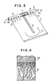
- FIG. 3 is a perspective view of a part of the spiral wound gas permeable membrane module shown in FIG. 1.
- FIG. 4 is an enlarged partial sectional view of a membrane used in the spiral wound gas permeable membrane module shown in FIG. 1.
- FIG. 5 is a block diagram of an apparatus using the spiral wound gas permeable membrane module shown in FIG. 1 for degasifying a gas from a liquid.
- FIG. 6 is a perspective view of a part of a spiral wound gas permeable membrane module according to another embodiment of the present invention.
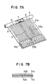
- FIG. 7A is a perspective view of a part of a spiral wound gas permeable membrane module according to a further embodiment of the present invention.
- FIG. 7B is a partial sectional view of the permeation side spacer of the module shown in FIG. 7A.
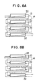
- FIGS. 8A to 8D are block diagrams of apparatuses according to the present invention, showing variations of the connection of a plurality of spiral wound gas permeable membrane modules.
- FIG. 9 is a block diagram of an apparatus using the spiral wound gas permeable membrane module shown in FIG. 1 for charging a gas into a liquid.
- FIG. 10 is a perspective view of a conventional spiral wound gas permeable membrane module at its unwound state.
- FIGS. 1-4 illustrate a spiral wound gas permeable membrane module according to an embodiment of the present invention
- FIG. 5 illustrates an apparatus using the spiral wound gas permeable membrane module.
- a spiral wound gas permeable membrane module 1 has a hollow mandrel 2 at the radial central portion, at least one envelope-like gas permeable membrane 3 around the mandrel, at least one feed water spacer 4 around the mandrel and at least one permeation side spacer 5 in the envelope-like gas permeable membrane.
- Hollow mandrel 2 has a plurality of holes 6 (FIG. 3) on the surface which are aligned in the longitudinal direction of the mandrel.
- a partition block 7 is provided in hollow mandrel 2 at the longitudinally central position as means for substantially blocking the flow of a gas flowing in the mandrel in its longitudinal direction. A part of the plurality of holes 6 are positioned on one side relative to partition block 7 and the remaining holes 6 are positioned on the other side relative to the partition block. Hollow mandrel 2 are opened at its both ends 2a and 2b.
- Envelope-like gas permeable membrane 3 is formed by turning a plane gas permeable membrane sheet and sealing both sides of the turned membrane sheet with an adhesive (sealed portion 8). Envelope-like gas permeable membrane 3 thus formed is connected to the side surface of mandrel 2 at the opening side end of the envelope-like gas permeable membrane to communicate the interior of the mandrel with the interior of the envelope-like gas permeable membrane through holes 6. Then, envelope-like gas permeable membrane 3 connected to mandrel 2 is spirally wrapped around the mandrel. A flow regulating wall 9 is provided in envelope-like gas permeable membrane 3 as means for regulating the flow of the gas in the envelope-like gas permeable membrane.
- Flow regulating wall 9 extends from the outer surface of mandrel substantially at the position of partition block 7 to an outer position in envelope-like gas permeable membrane 3 so that both side portions of the flow regulating wall substantially do not directly communicate with each other.
- This flow regulating wall 9 regulates the flow of the gas flown into the interior of envelope-like gas permeable membrane 3 through holes 6 aligned on one side relative to partition block 7 so that the gas travels in the envelope-like gas permeable membrane in the spiral outer direction and then backs in the spiral inner direction and flows into mandrel 2 through the holes aligned on the other side relative to the partition block, as shown by arrows 10, 11 and 12 in FIGS. 1 and 3.
- Feed water spacer 4 is provided on the outer surfaces of the spirally wrapped envelope-like gas permeable membrane 3 and wrapped together with the envelope-like gas permeable membrane.
- a raw liquid 13, for example, a raw water is supplied to and flown along the passageway formed by feed water spacer 4 as shown by arrows in FIG. 1.
- Permeation side spacer 5 is provided in envelope-like gas permeable membrane 3 to form the passageway for a gas and wrapped together with the envelope-like gas permeable membrane.
- feed water spacers 4 and permeation side spacers 5 are arranged alternately as shown in FIG. 2.
- the kind of the hydrophobic gas permeable membrane used as envelope-like gas permeable membrane 3 of the above module 1 is not particularly restricted.
- the membrane may be a plane polymer membrane having a gas permeation property capable of separating a gas dissolved in a raw liquid from the raw liquid through the membrane.
- the membrane is preferably composed of a polymer selected from the group consisting of silicone-based, fluorine-containing and polyolefine-based polymers.
- the membrane comprises a supporting layer 21 consisting of a porous material formed from a polymer and a homogeneous or dense layer 22, as shown in FIG. 4.
- a homogeneous layer means a layer composed of the same polymer material as that of the porous supporting layer 21 or a polymer material different from that of the porous supporting layer, and the homogeneous layer is made separate from the porous supporting layer.
- a dense layer means a layer composed of the same polymer material as that of the porous supporting layer 21, and the dense layer is made together with the porous supporting layer in a single process.
- the polymer suitable for the porous supporting layer is selected from, for example, the group consisting of polyester, polyamide, polyolefine, polyacrylate, polymethacrylate, Teflon (polytetrafluorideethylene), silicone, polysulfone and polycarbonate. Particularly, polysulfone and polypropylene are preferable.
- the thickness of the porous supporting layer can be freely determined, the thickness is preferably in the range of from several microns to several millimeters.
- the porosity of the porous supporting layer is preferably in the range of 10-80 %.
- This porous supporting layer operates to support the homogeneous or fine polymer layer.
- the size of pores on the surface is preferably in the range of 10-5,000 ⁇ , more preferably in the range of 10-1,000 ⁇ .
- the porous supporting layer preferably has an asymmetric structure to suppress the resistance when a gas permeates through the membrane.
- the homogeneous or dense layer is preferably composed of a polymer having a oxygen permeation coefficient of not less than 1 x 10 ⁇ 8 (cm3 ⁇ cm/cm2 ⁇ cmHg ⁇ sec).
- a polymer is selected from the group consisting of polyorganosiloxane, polyorganosiloxane/polycarbonate copolymer, polyorganosiloxane/polyphenylene copolymer, polyorganosiloxane/polystyrene copolymer and polytrimethylsililpropyne.
- crosslinkage type polydimethylsiloxane is the most preferable from the viewpoints of mechanical strength and oxygen permeation coefficient.
- the thickness of the homogeneous or dense layer is preferably small from the viewpoint of gas permeation ability, a layer having a too small thickness is not desirable because pin holes are likely to occur.
- the thickness of the homogeneous or dense layer is preferably about 0.1 ⁇ m.
- feed water spacer 4 is not particularly restricted.
- feed water spacer 4 is preferably constructed of a net, particularly a plastic net, which causes a low pressure loss for the raw liquid supplied to the feed water spacer.
- a net having a thickness of 0.3-2.0 mm and whose material is polyethylene, nylon or polypropylene is suitable for the feed water spacer.
- the kind and shape of permeation side spacer 5 provided in envelope-like gas permeable membrane 3 also are not particularly restricted.
- permeation side spacer 5 is also preferably constructed of a net, particularly a plastic net.
- a polypropylene net having an appropriate rigidity and capable of causing a small pressure loss for the flow of the gas is suitable.
- polyester fabrics having grooves which extend in one direction can be used for the permeation side spacer as described later.
- the material and shape of flow regulating wall 9 is not particularly restricted, and the flow regulating wall may be formed as one which enables the completion of the module and can regulate the flow of a gas in the envelope-like gas permeable membrane.
- the flow regulating wall can be formed by applying an adhesive to a required portion and curing it, or by providing an elastic material shaped in the form of a sheet or a strip in the envelope-like gas permeable membrane and fixing or bonding it.
- the latter elastic material is selected from, for example, a silicone rubber, a foamed plastic sheet, a nitrile rubber or other elastic plastic sheets.
- the material of partition block 7 also is not particularly restricted, and the material may be one which substantially can block the flow of a gas in the longitudinal direction of mandrel 2.
- the material is selected from a hard vinyl chloride, an ABS resin, a nylon or a rubber.
- the partition block may be bonded to the inner surface of hollow mandrel 2 or not.
- the above spiral wound gas permeable membrane module 1 shown in FIGS. 1-4 is used as follows.
- a raw liquid 13 is flown on the outer surfaces of envelope-like gas permeable membrane 3 along the passageway of feed water spacer 4, for example, in the axial direction in parallel to hollow mandrel 2 as shown in FIG. 1.
- This raw liquid 13 contains a gas to be degasified.
- the raw liquid 13 is supplied from a liquid supply pump 31 provided as a liquid supplying means and connected to a housing 32 containing at least one spiral wound gas permeable membrane module 1 therein, as shown in FIG. 5.
- the kind of the raw liquid is not particularly restricted.
- the raw liquid is a city water, an industrial water, a super pure water, a process water for food industry, etc.
- the raw liquid may be other aqueous solution or a solution such as a chemical solution other than nonaqueous solution.
- a carrier gas 14 (FIG. 3) is flown on the back surfaces of envelope-like gas permeable membrane 3 along the passageway of permeation side spacer 5.
- the carrier gas 14 is flown into the inside of hollow mandrel 2 through end opening 2a.
- the carrier gas 14 is then flown into the interior of envelope-like gas permeable membrane 3 through holes 6 aligned on one side relative to partition block 7. At that time, the carrier gas 14 does not flow directly towards the other end opening 2b, because partition block 7 blocks the flow of the carrier gas in mandrel.
- the carrier gas 14 flows in envelope-like gas permeable membrane 3 along the passageway of permeation side spacer 5, in the spiral outer direction and then in the spiral inner direction after turning while the flow is regulated by flow regulating wall 9 as shown by arrows 10, 11 and 12 in FIG. 3. Then, the carrier gas 14 flows into the inside of hollow mandrel 2 through holes 6 aligned on the other side relative to partition block 7, and flows out from the other end opening 2b.
- the carrier gas flows out from the other end opening 2b, the gas becomes to be a gas 15 containing the carrier gas and a gas permeated from the raw liquid 13 through envelope-like gas permeable membrane 3.
- This carrier gas 14 is supplied from a carrier gas source 33 connected to end opening 2a of the module 1 assembled in housing 32 as shown in FIG. 5.
- the carrier gas 14 flown out from the module 1 is preferably sucked by a vacuum pump 34 connected to the other end opening 2b.
- the carrier gas 14 is a gas basically different from the gas to be degasified from the raw liquid.
- the carrier gas 14 flowing in envelope-like gas permeable membrane 3 purges the residual gas in the envelope-like gas permeable membrane and the gas permeated from the raw liquid 13 through the envelope-like gas permeable membrane. Therefore, the partial gas pressure of the gas to be degasified on the permeation side can be extremely reduced, for example, to be nearly equal to zero. As a result, the degasification ability of the module 1 is increased to a great extent.
- the carrier gas 14 may be a gas which substantially does not contain the gas to be degasified from the raw liquid, and can be selected depending upon some circumstances.
- nitrogen or carbon dioxide can be used as the carrier gas.
- nitrogen may be used as the carrier gas.
- the flow rate of the carrier gas 14 can be determined by a target dissolved gas concentration of the raw liquid after the degasification by the module.
- a target dissolved gas concentration of the raw liquid after the degasification by the module For example, when nitrogen is used as the carrier gas, preferable flow rate of the carrier gas is in the range of 5-10 % of the flow rate of the raw water by volume.
- the flow regulating wall 9 can be formed in an appropriate length, number or location, depending upon the use of the module 1.
- two partition blocks 41a and 41b are provided in a hollow mandrel 42, and two flow regulating walls 43a and 43b positioned to correspond to the positions of the respective partition blocks 41a and 41b and extending to an intermediate position in an envelope-like gas permeable membrane 44 and one flow regulating wall 43c positioned at the central position of the mandrel in its longitudinal direction and extending over the entire length from the outer surface of the mandrel to the spiral outer end in the envelope-like gas permeable membrane 44 are formed in the envelope-like gas permeable membrane.
- the permeation side spacer 5 also can be modified to various materials and shapes.
- the permeation side spacer may be constructed by the combination of a tricot 51a having grooves 52a extending in one direction 53a and another tricot 51b having grooves 52b extending in the direction 53b substantially perpendicular to the direction 53a.
- the tricot 51a and tricot 51b are stacked such that their surfaces having the grooves 52a and 52b face each other.
- the gas flowing in envelope-like gas permeable membrane 3 flows along the grooves 52a of tricot 51a from holes 6 aligned on one side relative to partition block 7 in the spiral outer direction, then flows along the grooves 52b of tricot 51b in the axial direction, and thereafter flows along the grooves 52a of tricot 51a towards holes 6 aligned on the other side relative to partition block 7 in the spiral inner direction.
- Any one of tricot 51a and tricot 51b may be provided in envelope-like gas permeable membrane 3, and only a part of them may be provided in the envelope-like gas permeable membrane.
- the degasification ability can be increased by connecting a plurality of modules 1.
- a plurality of housings 32 are connected in series as shown in FIGS. 8A-8C or in parallel as shown in FIG. 8D.
- the connection in series is preferable.
- the connection in parallel is preferable.
- the carrier gas 14 since the carrier gas 14 flows through the plurality of housings 32 in order, it is expected that the concentration of the gas degasified from the raw liquid 13 in the carrier gas becomes gradually higher and the efficiency of the degasification gradually decreases. According to the investigation by the inventors of the present invention, however, it has been found that the efficiency of the degasification can be easily controlled by the flow rate of the carrier gas even if the purity of the carrier gas is reduced to some extent accompanying with the flow through the plurality of housings 32 connected in series, and that the running cost can be greatly reduced as compared with the case where the carrier gas is supplied in parallel.
- the carrier gas 14 may be supplied in the same manner and the same order as that of the raw liquid 13 as shown in FIG. 8A.
- the carrier gas 14 and the raw liquid 13 may be supplied in counter flow to each other as shown in FIG. 8B. Further, the carrier gas 14 may be supplied by any other path as shown in FIG. 8C.
- the counter flow supply such as one shown in FIG. 8B is preferable from the viewpoint of obtaining a high degasification efficiency because the raw liquid of exit side is exposed to the carrier gas of entrance side having the highest purity.
- the spiral wound gas permeable membrane module 1 according to the present invention can be used for charging a gas into a liquid.
- FIG. 9 illustrates a typical system for such a gas charging which uses a housing 32 containing a single or a plurality of spiral wound gas permeable membrane modules 1.
- a liquid 61 for example, water
- a gas 64 to be charged into the liquid 61 is supplied to the passageway of permeation side spacer 5 of the spiral wound gas permeable membrane module 1.
- a vent line 65 is connected to the exit side of mandrel 2.
- the pressure of the supplied gas 64 is maintained to a relatively high pressure.
- the gas 64 permeates through envelope-like gas permeable membrane 3 from the side of permeation side spacer 5 to the side of feed water spacer 4, and charged into the liquid 61.
- the liquid charged with gas 64 is delivered out from the housing 32 as a charged liquid 66.
- a part of the charged liquid 66 may be returned to the liquid supply line by a bypass line 67 in order to increase the degree of the charge.
- the gas to be charge is not particularly restricted. Oxygen and carbon dioxide are preferably used as the gas.
- the gas 64 is charged into the liquid 61 via a broad area of the envelope-like gas permeable membrane 3 because the gas is introduced into the interior of the envelope-like membrane and the flow of the gas is regulated by flow regulating wall 9 over the broad area in the envelope-like membrane. Therefore, the efficiency of the gas charging is very high. Moreover, since the gas charging is performed by utilizing the equilibrium condition between the gas and the liquid, the gas is not charged over than the saturated state of the charged liquid. Accordingly, bubbles due to lack of dissolution of the gas into the liquid does not occur. Further, since the pressure loss of the supplied liquid between the entrance side and exit side of the housing 32 is relatively small, a uniform charging can be performed even if the pressure of the supplied liquid is small. Furthermore, the concentration of the gas in the charged liquid can be easily controlled to a desired value by adjusting the pressure of the supplied liquid, the gas pressure, the flow rate of the gas or the temperature of the liquid.
- a hydrophobic gas permeable membrane obtained by forming a silicone thin layer on a porous supporting layer composed of polyester taffeta/polysulfone was wrapped around a hollow mandrel composed of a hard vinyl chloride together with a permeation side spacer composed of a polypropylene net with a thickness of 0.3 mm and a feed water spacer composed of a polypropylene net with a thickness of 0.6 mm.
- the module was contained in a housing.
- the degasification ability of the module was determined by supplying nitrogen as a carrier gas.
- the flow rate of a raw water was 1,000 1/h
- the degree of vacuum of the permeation side was controlled to 85 Torr
- the flow rate of nitrogen was 1,000 cc/min
- the operation temperature was 25°C.
- the initial degree of concentration of the dissolved oxygen of 8. 0 ppm in the raw water was reduced to 1.9 ppm.
- the degasified raw water in the above manner (the degree of concentration of the dissolved oxygen : 1.9 ppm) was again degasified in the same manner.
- the degree of concentration of the dissolved oxygen was reduced to 0.5 ppm.
- Example 2 The same parts as those of Example 1 other than no flow regulating wall were used to make a spiral wound gas permeable membrane module.
- the degasification ability of the module was determined after incorporating the module into a housing without providing a partition block in the hollow mandrel and without supplying a carrier gas.
- the flow rate of a raw water was 1,000 1/h
- the degree of vacuum of the permeation side was controlled to 85 Torr
- the operation temperature was 25 °C.
- the initial degree of concentration of the dissolved oxygen of 8.0 ppm in the raw water was reduced to 2.7 ppm.
- nitrogen was supplied to the module as a carrier gas at 1,000 cc/min by flow rate, under the same conditions.
- the degree of concentration of the dissolved oxygen was reduced to 2.5 ppm.
- the degasified raw water (the degree of concentration of the dissolved oxygen : 1.4 ppm) was again degasified in the same manner as described above without supplying nitrogen. As a result, the degree of concentration of the dissolved oxygen was reduced only to 1.2 ppm.
- Example 2 Four spiral wound gas permeable membrane modules having the same structure as that of Example 1, which had the flow regulating wall and the partition block, were made. Each module was incorporated into each of four housings. The four housings were connected in series in the manner shown in FIG. 8C to make a degasification apparatus. The degasification ability of the module was determined by supplying nitrogen as a carrier gas. The flow rate of a raw water was 1,000 1/h, the degree of vacuum of the permeation side was controlled to 85 Torr, the flow rate of nitrogen was 1,500 cc/min, and the operation temperature was 25 °C. As a result, the initial degree of concentration of the dissolved oxygen of 8.0 ppm in the raw water was reduced to 0.2 ppm.
- Example 3 The same spiral wound gas permeable membrane modules were used and the same apparatus was made as those of Example 3.
- Pure oxygen was supplied from a oxygen bomb to the apparatus as a gas to be charged into the water at a pressure of 2.0 kg/cm2.
- the concentration of the oxygen dissolved in the treated water was 8.2 ppm.
- the effect due to the gas charging was significantly recognized.
Abstract
Description
- The present invention relates to a spiral wound gas permeable membrane module using a hydrophobic gas permeable membrane and an apparatus and a method for using the same.
- Generally, gases such as oxygen, nitrogen and carbon dioxide are dissolved in a water, and sometimes these dissolved gases give a bad influence to a water treatment. For example, oxygen dissolved in a water often accelerates the corrosion of the inner surface of a pipe wetted by the water in a water circulation system, and carbon dioxide dissolved in a water often deteriorates the water quality of a super pure water produced by a water purifing system. In such cases, degasification treatment has been performed as required by, for example, addition of chemical or vacuum treatment as disclosed in, for instance, JP-A-SHO 58-14905, SHO 58-101784 and SHO 58-186490.
- In the conventional degasification by such a chemical treatment, however, there are problems such as the cost of chemical and residual components. Also there are restrictions such as the cost of the system and the running cost even in the vacuum treatment. Therefore, these conventional treatments have not truly served for a desired practical degasification.
- On the other hand, recently a method for degasifying dissolved gases from a raw water by using a hydrophobic membrane having a gas permeation property has been developed in practical use (for example, Japanese Utility Model Laid-Open SHO 57-35795, JP-A-SHO 62-273095). In this method, a raw water is flown on the surface or back surface of a membrane having a gas permeation property and a hydrophobic property, the other surface side is controlled to the condition of a reduced pressure, and thereby only the gas dissolved in the raw water is permeated through the membrane and removed from the raw water. This method has advantages that there is no residual chemical left which is the problem in the conventional chemical addition method and that the apparatus or system for this method is simple and the running cost thereof is inexpensive as compared with the conventional vacuum degasification method.
- In the degasification using a hydrophobic gas permeable membrane, the membrane forms a unit of a module. As the types of such gas permeable membrane modules, a spiral type and a hollow yarn type are known depending upon the formation of the membrane (for example, JP-A-HEI 2-2802, Japanese Utility Model Laid-Open HEI 2-25096). In a case where the amount of gas to be degasified is large, it is considered that a spiral type module using a plane gas permeable membrane is good. A typical conventional spiral module is constructed, for example, as shown in FIG. 10. The spiral module shown in FIG. 10 basically has the same structure as those disclosed in JP-B-SHO 44-14216, Jp-A-SHO 54-31087 and JP-A-SHO 56-129006 which are used for the separation of liquids. In FIG. 10, a unit comprises an envelope-like hydrophobic gas
permeable membrane 105 sealed at its bothside edges 102, apermeation side spacer 106 provided in the envelope-like membrane and afeed water spacer 104 on the outer surface of the envelope-like membrane, and one or a plurality of the units are wrapped around ahollow mandrel 101 which has a plurality of holes on its surface and whose one end is plugged and the other end 101a is opened.Raw water 107 is supplied to the outer surface side of envelope-like membrane 105, and the gas pressure in the envelope-like membrane is reduced by the suction by a pressure reducing source connected to opening end 101a ofhollow mandrel 101 to cause a pressure difference between the surface and the back surface of hydrophobic gaspermeable membrane 105. The gas dissolved inraw water 107 permeates from the surface of envelope-like membrane 105 to its back surface, and the permeatedgas 103 flows along the passageway ofpermeation side spacer 106 in the envelope-like membrane towardshollow mandrel 101. Thus, the dissolved gas is removed fromraw water 107. - In such a degasification, however, since the degasification ability greatly depends on the difference between the partial gas pressures of the surface side and back surface side of the membrane as well as on the specific gas permeation property of the membrane itself, it is necessary to reduce the partial gas pressure of the gas permeation side by elevating the degree of vacuum of the gas permeation side of the membrane, or to increase the supply pressure of the raw water supplied to the module, i.e., to the surface side of the membrane, in order to increase the degasification ability of the module. However, the degree of vacuum of the gas permeation side and the supply pressure of the raw water are both limited to certain levels from the viewpoint of practical use, therefore it is difficult to further increase the degasification ability.
- Accordingly, it would be desirable to provide a spiral wound gas permeable membrane module having a sufficiently high degasification ability even at a usual degree of vacuum of the gas permeation side of the membrane or a usual supply pressure of a raw liquid supplied to the module.
- Further, it would be desirable to provide apparatuses using such a spiral wound gas permeable membrane module for degasifying a gas from a raw liquid or charging a gas into a liquid with a high efficiency.
- Still further, it would be desirable to provide methods for using the spiral wound gas permeable membrane module to degasify a gas from a raw liquid or charge a gas into a liquid with a high efficiency.
- A spiral wound gas permeable membrane module according to the present invention is herein provided. The spiral wound gas permeable membrane module has a hollow mandrel with a plurality of longitudinally aligned holes, at least one envelope-like gas permeable membrane connected to the side surface of the mandrel at the opening side end of the envelope-like gas permeable membrane to communicate the interior of the mandrel with the interior of the envelope-like gas permeable membrane through the holes and spirally wrapped around the mandrel, at least one feed water spacer spirally wrapped around the mandrel so that the feed water spacer is positioned on the outer surfaces of the spirally wrapped envelope-like gas permeable membrane, and at least one permeation side spacer provided in the envelope-like gas permeable membrane. The spiral wound gas permeable membrane module comprises means provided in the mandrel for substantially blocking the flow of a gas flowing in the mandrel in its longitudinal direction and means provided in the envelope-like gas permeable membrane for regulating the flow of the gas flown into the envelope-like gas permeable membrane through the holes aligned on one side relative to the flow blocking means so that the gas travels in the envelope-like gas permeable membrane in the spiral outer direction and then backs in the spiral inner direction and flows into the mandrel through the holes aligned on the other side relative to the flow blocking means.
- An apparatus for degasification according to the present invention includes at least one above spiral wound gas permeable membrane module, and comprises means for supplying a raw liquid to the passageway of the feed water spacer of the module and means for supplying a carrier gas to one of the end openings of the mandrel of the module.
- An apparatus for charging a gas into a liquid according to the present invention includes at least one above spiral wound gas permeable membrane module, and comprises means for supplying the liquid to the passageway of the feed water spacer of the module and means for supplying the gas to be charged to one of the end openings of the mandrel of the module.
- A method for using at least one above spiral wound gas permeable membrane module according to the present invention comprises the steps of supplying a raw liquid to the passageway of the feed water spacer so that the raw liquid flows on and along the outer surfaces of the spirally wrapped envelope-like gas permeable membrane; and supplying a carrier gas substantially other than a gas to be degasified from the raw liquid to one of the end openings of the mandrel so that the carrier gas flows from the one end opening to the other end opening of the mandrel through the interior of the envelope-like gas permeable membrane and the holes aligned on both sides relative to the flow blocking means.
- A method for using at least one above spiral wound gas permeable membrane module according to the present invention comprises the steps of supplying a liquid to the passageway of the feed water spacer so that the liquid flows on and along the outer surfaces of the spirally wrapped envelope-like gas permeable membrane; and supplying a gas to be charged into the liquid to one of the end openings of the mandrel so that the gas flows from the one end opening to the other end opening of the mandrel through the interior of the envelope-like gas permeable membrane and the holes aligned on both sides relative to the flow blocking means.
- In the spiral wound gas permeable membrane module, a carrier gas substantially different from a gas to be degasified from a raw liquid is flown into one of the end openings of the mandrel, the carrier gas flows from the inside of the mandrel into the interior of the envelope-like gas permeable membrane through the holes aligned on one side relative to the flow blocking means, the carrier gas flows in the envelope-like gas permeable membrane so as to travel in the spiral outer direction and then back in the spiral inner direction towards the mandrel by the regulation of the flow by the flow regulating means, and the carrier gas flows into the inside of the mandrel through the holes aligned on the other side relative to the flow blocking means and flows out from the other opening of the mandrel. The flow of the carrier gas in the envelope-like gas permeable membrane can purge the residual gas present in the membrane and the gas permeated through the membrane from the raw liquid, and the partial gas pressure of the gas to be degasified on the back surface side of the membrane can be extremely reduced, for example, to be nearly equal to zero. As a result, the difference between the partial gas pressures of the gas to be degasified on the surface side and the back surface side of the membrane becomes very great, and the degasification ability due to the gas permeable membrane can be greatly increased.
- In the conventional module such as one shown in FIG. 10, most of the carrier gas passes through the inside of the mandrel from one end opening thereof directly to the other end opening thereof without flowing into the envelope-like gas permeable membrane. Therefore, the degasification ability due to the gas permeable membrane is relatively low.
- Further, the spiral wound gas permeable membrane module according to the present invention can be used for charging a gas into a liquid as well as for degasification. In the charging, a gas to be charged is flown on the back surface side of the envelope-like gas permeable membrane and a liquid to be charged with the gas is flown on the surface side of the envelope-like gas permeable membrane. The gas pressure of the gas to be charged is desirably controlled to a relatively high pressure. Since the gas to be charged flows in the envelope-like gas permeable membrane in the spiral outer direction and backs in the spiral inner direction also in the gas charging operation, the gas is delivered broadly in the envelope-like gas permeable membrane and charged into the liquid through the membrane with a high efficiency.
- Some preferred exemplary embodiments of the invention will now be described with reference to the accompanying drawings, which are given by way of example only, and are not intended to limit the present invention.
- FIG. 1 is a perspective view of a spiral wound gas permeable membrane module at its unwound state according to an embodiment of the present invention.
- FIG. 2 is an enlarged partial sectional view of the spiral wound gas permeable membrane module shown in FIG. 1.
- FIG. 3 is a perspective view of a part of the spiral wound gas permeable membrane module shown in FIG. 1.
- FIG. 4 is an enlarged partial sectional view of a membrane used in the spiral wound gas permeable membrane module shown in FIG. 1.
- FIG. 5 is a block diagram of an apparatus using the spiral wound gas permeable membrane module shown in FIG. 1 for degasifying a gas from a liquid.
- FIG. 6 is a perspective view of a part of a spiral wound gas permeable membrane module according to another embodiment of the present invention.
- FIG. 7A is a perspective view of a part of a spiral wound gas permeable membrane module according to a further embodiment of the present invention.
- FIG. 7B is a partial sectional view of the permeation side spacer of the module shown in FIG. 7A.
- FIGS. 8A to 8D are block diagrams of apparatuses according to the present invention, showing variations of the connection of a plurality of spiral wound gas permeable membrane modules.
- FIG. 9 is a block diagram of an apparatus using the spiral wound gas permeable membrane module shown in FIG. 1 for charging a gas into a liquid.
- FIG. 10 is a perspective view of a conventional spiral wound gas permeable membrane module at its unwound state.
- Referring to the drawings, FIGS. 1-4 illustrate a spiral wound gas permeable membrane module according to an embodiment of the present invention and FIG. 5 illustrates an apparatus using the spiral wound gas permeable membrane module.
- A spiral wound gas
permeable membrane module 1 has ahollow mandrel 2 at the radial central portion, at least one envelope-like gaspermeable membrane 3 around the mandrel, at least onefeed water spacer 4 around the mandrel and at least onepermeation side spacer 5 in the envelope-like gas permeable membrane.Hollow mandrel 2 has a plurality of holes 6 (FIG. 3) on the surface which are aligned in the longitudinal direction of the mandrel. A partition block 7 is provided inhollow mandrel 2 at the longitudinally central position as means for substantially blocking the flow of a gas flowing in the mandrel in its longitudinal direction. A part of the plurality ofholes 6 are positioned on one side relative to partition block 7 and theremaining holes 6 are positioned on the other side relative to the partition block.Hollow mandrel 2 are opened at its bothends 2a and 2b. - Envelope-like gas
permeable membrane 3 is formed by turning a plane gas permeable membrane sheet and sealing both sides of the turned membrane sheet with an adhesive (sealed portion 8). Envelope-like gaspermeable membrane 3 thus formed is connected to the side surface ofmandrel 2 at the opening side end of the envelope-like gas permeable membrane to communicate the interior of the mandrel with the interior of the envelope-like gas permeable membrane throughholes 6. Then, envelope-like gaspermeable membrane 3 connected tomandrel 2 is spirally wrapped around the mandrel. A flow regulating wall 9 is provided in envelope-like gaspermeable membrane 3 as means for regulating the flow of the gas in the envelope-like gas permeable membrane. Flow regulating wall 9 extends from the outer surface of mandrel substantially at the position of partition block 7 to an outer position in envelope-like gaspermeable membrane 3 so that both side portions of the flow regulating wall substantially do not directly communicate with each other. This flow regulating wall 9 regulates the flow of the gas flown into the interior of envelope-like gaspermeable membrane 3 throughholes 6 aligned on one side relative to partition block 7 so that the gas travels in the envelope-like gas permeable membrane in the spiral outer direction and then backs in the spiral inner direction and flows intomandrel 2 through the holes aligned on the other side relative to the partition block, as shown byarrows -
Feed water spacer 4 is provided on the outer surfaces of the spirally wrapped envelope-like gaspermeable membrane 3 and wrapped together with the envelope-like gas permeable membrane. Araw liquid 13, for example, a raw water is supplied to and flown along the passageway formed byfeed water spacer 4 as shown by arrows in FIG. 1.Permeation side spacer 5 is provided in envelope-like gaspermeable membrane 3 to form the passageway for a gas and wrapped together with the envelope-like gas permeable membrane. - In a case of using a plurality of sets of envelope-like gas
permeable membranes 3, feedwater spacers 4 andpermeation side spacers 5, these element are arranged alternately as shown in FIG. 2. - The kind of the hydrophobic gas permeable membrane used as envelope-like gas
permeable membrane 3 of theabove module 1 is not particularly restricted. The membrane may be a plane polymer membrane having a gas permeation property capable of separating a gas dissolved in a raw liquid from the raw liquid through the membrane. - The membrane is preferably composed of a polymer selected from the group consisting of silicone-based, fluorine-containing and polyolefine-based polymers. For example, the membrane comprises a supporting
layer 21 consisting of a porous material formed from a polymer and a homogeneous ordense layer 22, as shown in FIG. 4. Where, a homogeneous layer means a layer composed of the same polymer material as that of the porous supportinglayer 21 or a polymer material different from that of the porous supporting layer, and the homogeneous layer is made separate from the porous supporting layer. A dense layer means a layer composed of the same polymer material as that of the porous supportinglayer 21, and the dense layer is made together with the porous supporting layer in a single process. - The polymer suitable for the porous supporting layer is selected from, for example, the group consisting of polyester, polyamide, polyolefine, polyacrylate, polymethacrylate, Teflon (polytetrafluorideethylene), silicone, polysulfone and polycarbonate. Particularly, polysulfone and polypropylene are preferable. Although the thickness of the porous supporting layer can be freely determined, the thickness is preferably in the range of from several microns to several millimeters. The porosity of the porous supporting layer is preferably in the range of 10-80 %.
- This porous supporting layer operates to support the homogeneous or fine polymer layer. The size of pores on the surface is preferably in the range of 10-5,000 Å, more preferably in the range of 10-1,000Å. The porous supporting layer preferably has an asymmetric structure to suppress the resistance when a gas permeates through the membrane.
- The homogeneous or dense layer is preferably composed of a polymer having a oxygen permeation coefficient of not less than 1 x 10 ⁻⁸ (cm³ · cm/cm² · cmHg · sec). Such a polymer is selected from the group consisting of polyorganosiloxane, polyorganosiloxane/polycarbonate copolymer, polyorganosiloxane/polyphenylene copolymer, polyorganosiloxane/polystyrene copolymer and polytrimethylsililpropyne. Particularly, crosslinkage type polydimethylsiloxane is the most preferable from the viewpoints of mechanical strength and oxygen permeation coefficient. Although the thickness of the homogeneous or dense layer is preferably small from the viewpoint of gas permeation ability, a layer having a too small thickness is not desirable because pin holes are likely to occur. For example, the thickness of the homogeneous or dense layer is preferably about 0.1µm.
- The kind of
feed water spacer 4 also is not particularly restricted. However, feedwater spacer 4 is preferably constructed of a net, particularly a plastic net, which causes a low pressure loss for the raw liquid supplied to the feed water spacer. For example, a net having a thickness of 0.3-2.0 mm and whose material is polyethylene, nylon or polypropylene is suitable for the feed water spacer. The kind and shape ofpermeation side spacer 5 provided in envelope-like gaspermeable membrane 3 also are not particularly restricted. However,permeation side spacer 5 is also preferably constructed of a net, particularly a plastic net. In particular, a polypropylene net having an appropriate rigidity and capable of causing a small pressure loss for the flow of the gas is suitable. Alternatively, polyester fabrics having grooves which extend in one direction can be used for the permeation side spacer as described later. - The material and shape of flow regulating wall 9 is not particularly restricted, and the flow regulating wall may be formed as one which enables the completion of the module and can regulate the flow of a gas in the envelope-like gas permeable membrane. For example, the flow regulating wall can be formed by applying an adhesive to a required portion and curing it, or by providing an elastic material shaped in the form of a sheet or a strip in the envelope-like gas permeable membrane and fixing or bonding it. The latter elastic material is selected from, for example, a silicone rubber, a foamed plastic sheet, a nitrile rubber or other elastic plastic sheets.
- The material of partition block 7 also is not particularly restricted, and the material may be one which substantially can block the flow of a gas in the longitudinal direction of
mandrel 2. For example, the material is selected from a hard vinyl chloride, an ABS resin, a nylon or a rubber. The partition block may be bonded to the inner surface ofhollow mandrel 2 or not. - The above spiral wound gas
permeable membrane module 1 shown in FIGS. 1-4 is used as follows. - A
raw liquid 13 is flown on the outer surfaces of envelope-like gaspermeable membrane 3 along the passageway offeed water spacer 4, for example, in the axial direction in parallel tohollow mandrel 2 as shown in FIG. 1. This raw liquid 13 contains a gas to be degasified. Theraw liquid 13 is supplied from aliquid supply pump 31 provided as a liquid supplying means and connected to ahousing 32 containing at least one spiral wound gaspermeable membrane module 1 therein, as shown in FIG. 5. The kind of the raw liquid is not particularly restricted. Usually the raw liquid is a city water, an industrial water, a super pure water, a process water for food industry, etc. However, the raw liquid may be other aqueous solution or a solution such as a chemical solution other than nonaqueous solution. - On the other hand, a carrier gas 14 (FIG. 3) is flown on the back surfaces of envelope-like gas
permeable membrane 3 along the passageway ofpermeation side spacer 5. Thecarrier gas 14 is flown into the inside ofhollow mandrel 2 through end opening 2a. Thecarrier gas 14 is then flown into the interior of envelope-like gaspermeable membrane 3 throughholes 6 aligned on one side relative to partition block 7. At that time, thecarrier gas 14 does not flow directly towards theother end opening 2b, because partition block 7 blocks the flow of the carrier gas in mandrel. Thereafter, thecarrier gas 14 flows in envelope-like gaspermeable membrane 3 along the passageway ofpermeation side spacer 5, in the spiral outer direction and then in the spiral inner direction after turning while the flow is regulated by flow regulating wall 9 as shown byarrows carrier gas 14 flows into the inside ofhollow mandrel 2 throughholes 6 aligned on the other side relative to partition block 7, and flows out from theother end opening 2b. When the carrier gas flows out from theother end opening 2b, the gas becomes to be agas 15 containing the carrier gas and a gas permeated from theraw liquid 13 through envelope-like gaspermeable membrane 3. Thiscarrier gas 14 is supplied from acarrier gas source 33 connected to end opening 2a of themodule 1 assembled inhousing 32 as shown in FIG. 5. Thecarrier gas 14 flown out from themodule 1 is preferably sucked by a vacuum pump 34 connected to theother end opening 2b. - The
carrier gas 14 is a gas basically different from the gas to be degasified from the raw liquid. Thecarrier gas 14 flowing in envelope-like gaspermeable membrane 3 purges the residual gas in the envelope-like gas permeable membrane and the gas permeated from theraw liquid 13 through the envelope-like gas permeable membrane. Therefore, the partial gas pressure of the gas to be degasified on the permeation side can be extremely reduced, for example, to be nearly equal to zero. As a result, the degasification ability of themodule 1 is increased to a great extent. - The
carrier gas 14 may be a gas which substantially does not contain the gas to be degasified from the raw liquid, and can be selected depending upon some circumstances. For example, in a case where oxygen contained in a raw water is degasified, nitrogen or carbon dioxide can be used as the carrier gas. In a case where carbon dioxide contained in a raw water is degasified together with oxygen, nitrogen may be used as the carrier gas. - The flow rate of the
carrier gas 14 can be determined by a target dissolved gas concentration of the raw liquid after the degasification by the module. For example, when nitrogen is used as the carrier gas, preferable flow rate of the carrier gas is in the range of 5-10 % of the flow rate of the raw water by volume. - The flow regulating wall 9 can be formed in an appropriate length, number or location, depending upon the use of the
module 1. For example, as shown in FIG. 6, twopartition blocks 41a and 41b are provided in ahollow mandrel 42, and twoflow regulating walls respective partition blocks 41a and 41b and extending to an intermediate position in an envelope-like gaspermeable membrane 44 and oneflow regulating wall 43c positioned at the central position of the mandrel in its longitudinal direction and extending over the entire length from the outer surface of the mandrel to the spiral outer end in the envelope-like gaspermeable membrane 44 are formed in the envelope-like gas permeable membrane. The carrier gas and the gas degasified from the raw liquid flow as shown by arrows in FIG. 6. In such a structure, more efficient degasification will be expected. - The
permeation side spacer 5 also can be modified to various materials and shapes. For example, as shown in FIGS. 7A and 7B, the permeation side spacer may be constructed by the combination of a tricot51a having grooves 52a extending in onedirection 53a and another tricot51b having grooves 52b extending in thedirection 53b substantially perpendicular to thedirection 53a. The tricot 51a and tricot 51b are stacked such that their surfaces having thegrooves permeable membrane 3 flows along thegrooves 52a of tricot 51a fromholes 6 aligned on one side relative to partition block 7 in the spiral outer direction, then flows along thegrooves 52b of tricot 51b in the axial direction, and thereafter flows along thegrooves 52a of tricot 51a towardsholes 6 aligned on the other side relative to partition block 7 in the spiral inner direction. Any one of tricot 51a and tricot 51b may be provided in envelope-like gaspermeable membrane 3, and only a part of them may be provided in the envelope-like gas permeable membrane. - In the operation of the degasification by using spiral wound gas
permeable membrane module 1, although a sufficiently large degasification ability can be achieved by a single spiral wound gaspermeable membrane module 1 in comparison with a conventional module, the degasification ability can be increased by connecting a plurality ofmodules 1. Usually, one to six modules are contained in ahousing 32. When the degasification ability is desired to be further increased, a plurality ofhousings 32 are connected in series as shown in FIGS. 8A-8C or in parallel as shown in FIG. 8D. In a case where the degree of degasification is desired to be increased, the connection in series is preferable. In a case where the capacity of degasification is desired to be increased, the connection in parallel is preferable. In the connection in series, since thecarrier gas 14 flows through the plurality ofhousings 32 in order, it is expected that the concentration of the gas degasified from theraw liquid 13 in the carrier gas becomes gradually higher and the efficiency of the degasification gradually decreases. According to the investigation by the inventors of the present invention, however, it has been found that the efficiency of the degasification can be easily controlled by the flow rate of the carrier gas even if the purity of the carrier gas is reduced to some extent accompanying with the flow through the plurality ofhousings 32 connected in series, and that the running cost can be greatly reduced as compared with the case where the carrier gas is supplied in parallel. In the connection in series, thecarrier gas 14 may be supplied in the same manner and the same order as that of theraw liquid 13 as shown in FIG. 8A. Alternatively, thecarrier gas 14 and theraw liquid 13 may be supplied in counter flow to each other as shown in FIG. 8B. Further, thecarrier gas 14 may be supplied by any other path as shown in FIG. 8C. In particular, the counter flow supply such as one shown in FIG. 8B is preferable from the viewpoint of obtaining a high degasification efficiency because the raw liquid of exit side is exposed to the carrier gas of entrance side having the highest purity. - The spiral wound gas
permeable membrane module 1 according to the present invention can be used for charging a gas into a liquid. - FIG. 9 illustrates a typical system for such a gas charging which uses a
housing 32 containing a single or a plurality of spiral wound gaspermeable membrane modules 1. A liquid 61 (for example, water) is supplied to the passageway offeed water spacer 4 of spiral wound gaspermeable membrane module 1 incorporated intohousing 32 by asupply pump 62 through afilter 63. Agas 64 to be charged into the liquid 61 is supplied to the passageway ofpermeation side spacer 5 of the spiral wound gaspermeable membrane module 1. Avent line 65 is connected to the exit side ofmandrel 2. Preferably the pressure of the suppliedgas 64 is maintained to a relatively high pressure. Thegas 64 permeates through envelope-like gaspermeable membrane 3 from the side ofpermeation side spacer 5 to the side offeed water spacer 4, and charged into the liquid 61. The liquid charged withgas 64 is delivered out from thehousing 32 as a chargedliquid 66. A part of the charged liquid 66 may be returned to the liquid supply line by abypass line 67 in order to increase the degree of the charge. The gas to be charge is not particularly restricted. Oxygen and carbon dioxide are preferably used as the gas. - In such a gas charging, the
gas 64 is charged into the liquid 61 via a broad area of the envelope-like gaspermeable membrane 3 because the gas is introduced into the interior of the envelope-like membrane and the flow of the gas is regulated by flow regulating wall 9 over the broad area in the envelope-like membrane. Therefore, the efficiency of the gas charging is very high. Moreover, since the gas charging is performed by utilizing the equilibrium condition between the gas and the liquid, the gas is not charged over than the saturated state of the charged liquid. Accordingly, bubbles due to lack of dissolution of the gas into the liquid does not occur. Further, since the pressure loss of the supplied liquid between the entrance side and exit side of thehousing 32 is relatively small, a uniform charging can be performed even if the pressure of the supplied liquid is small. Furthermore, the concentration of the gas in the charged liquid can be easily controlled to a desired value by adjusting the pressure of the supplied liquid, the gas pressure, the flow rate of the gas or the temperature of the liquid. - Next, the present invention will be explained in more detail by examples. However, the present invention is not restricted by the examples.
- A hydrophobic gas permeable membrane obtained by forming a silicone thin layer on a porous supporting layer composed of polyester taffeta/polysulfone was wrapped around a hollow mandrel composed of a hard vinyl chloride together with a permeation side spacer composed of a polypropylene net with a thickness of 0.3 mm and a feed water spacer composed of a polypropylene net with a thickness of 0.6 mm. A spiral wound gas permeable membrane module, wherein a flow regulating wall was formed from an adhesive in the central portion of the envelope-like gas permeable membrane as shown in FIG. 3, the total membrane area of which was 8 m² and into which five sets of the envelope-like gas permeable membranes were incorporated, was made. After a partition block composed of a hard vinyl chloride was inserted into the hollow mandrel at the longitudinally central position and bonded to the inner surface of the mandrel, the module was contained in a housing. The degasification ability of the module was determined by supplying nitrogen as a carrier gas. The flow rate of a raw water was 1,000 1/h, the degree of vacuum of the permeation side was controlled to 85 Torr, the flow rate of nitrogen was 1,000 cc/min, and the operation temperature was 25°C. As a result, the initial degree of concentration of the dissolved oxygen of 8. 0 ppm in the raw water was reduced to 1.9 ppm. Next, the degasified raw water in the above manner (the degree of concentration of the dissolved oxygen : 1.9 ppm) was again degasified in the same manner. As a result, the degree of concentration of the dissolved oxygen was reduced to 0.5 ppm.
- The same parts as those of Example 1 other than no flow regulating wall were used to make a spiral wound gas permeable membrane module. The degasification ability of the module was determined after incorporating the module into a housing without providing a partition block in the hollow mandrel and without supplying a carrier gas. The flow rate of a raw water was 1,000 1/h, the degree of vacuum of the permeation side was controlled to 85 Torr, and the operation temperature was 25 °C. As a result, the initial degree of concentration of the dissolved oxygen of 8.0 ppm in the raw water was reduced to 2.7 ppm. Next, nitrogen was supplied to the module as a carrier gas at 1,000 cc/min by flow rate, under the same conditions. As a result, the degree of concentration of the dissolved oxygen was reduced to 2.5 ppm. Next, the degasified raw water (the degree of concentration of the dissolved oxygen : 1.4 ppm) was again degasified in the same manner as described above without supplying nitrogen. As a result, the degree of concentration of the dissolved oxygen was reduced only to 1.2 ppm.
- Four spiral wound gas permeable membrane modules having the same structure as that of Example 1, which had the flow regulating wall and the partition block, were made. Each module was incorporated into each of four housings. The four housings were connected in series in the manner shown in FIG. 8C to make a degasification apparatus. The degasification ability of the module was determined by supplying nitrogen as a carrier gas. The flow rate of a raw water was 1,000 1/h, the degree of vacuum of the permeation side was controlled to 85 Torr, the flow rate of nitrogen was 1,500 cc/min, and the operation temperature was 25 °C. As a result, the initial degree of concentration of the dissolved oxygen of 8.0 ppm in the raw water was reduced to 0.2 ppm.
- Two spiral wound gas permeable membrane modules having the same structure as that of Example 1 were made, and the modules were incorporated into a single housing. An apparatus having the system shown in FIG. 9 was made using this housing. A super pure water with a temperature of 2°C was supplied to the apparatus at a flow rate of 0.75 ton/h. At the same time, carbon dioxide was supplied into the envelope-like gas permeable membranes of the module at a pressure of 1.5 kg/cm². In this condition, the concentration of carbon dioxide dissolved in the water of exit side was determined. As a result, the concentration of carbon dioxide determined was 0.40 wt%. Where,
bypass line 67 was closed. - The same spiral wound gas permeable membrane modules were used and the same apparatus was made as those of Example 3. An examination water with a dissolved oxygen concentration of 1.2 ppm and a temperature of 25 °C, from which SS component was removed by SU-610RO module produced by Toray Industries, inc., was supplied to the apparatus. Pure oxygen was supplied from a oxygen bomb to the apparatus as a gas to be charged into the water at a pressure of 2.0 kg/cm². As a result, the concentration of the oxygen dissolved in the treated water was 8.2 ppm. Thus, the effect due to the gas charging was significantly recognized.
Claims (25)
- A spiral wound gas permeable membrane module (1) having a hollow mandrel (2, 42) with a plurality of longitudinally aligned holes (6), at least one envelope-like gas permeable membrane (3, 44) connected to the side surface of said mandrel (2, 42) at the opening side end of said envelope-like gas permeable membrane (3, 44) to communicate the interior of said mandrel (2, 42) with the interior of said envelope-like gas permeable membrane (3, 44) through said holes (6) and spirally wrapped around said mandrel (2, 42), at least one feed water spacer (4) spirally wrapped around said mandrel (2, 42) so that said feed water spacer (4) is positioned on the outer surfaces of said spirally wrapped envelope-like gas permeable membrane (3, 44), and at least one permeation side spacer (5) provided in said envelope-like gas permeable membrane (3, 44) characterized in that said spiral wound gas permeable membrane module (1) includes means (7, 41a, 41b) provided in said mandrel (2, 42) for substantially blocking the flow of a gas flowing in said mandrel (2, 42) in its longitudinal direction, and means (9, 43a, 43b, 43c) provided in said envelope-like gas permeable membrane (3, 44) for regulating the flow of said gas flown into said envelope-like gas permeable membrane (3, 44) through said holes (6) aligned on one side relative to said flow blocking means (7, 41a, 41b) so that the gas travels in said envelope-like gas permeable membrane (3, 44) in the spiral outer direction and then backs in the spiral inner direction and flows into said mandrel (2, 42) through said holes (6) aligned on the other side relative to said flow blocking means (7, 41a, 41b).
- The module (1) according to claim 1, wherein said flow regulating means (9, 43a, 43b, 43c) is formed by applying an adhesive in said envelope-like gas permeable membrane (3, 44) and curing the adhesive.
- The module (1) according to claim 1, wherein said flow regulating means (9, 43a, 43b, 43c) is constructed from an elastic polymer provided in said envelope-like gas permeable membrane (3, 44).
- The module (1) according to any preceding claim, wherein said gas permeable membrane (3, 44) is constructed of a polymer membrane having a gas permeation property.
- The module (1) according to claim 4, wherein said polymer membrane is composed of a polymer selected from the group consisting of silicone-based, fluorine-containing and polyolefine-based polymers.
- The module (1) according to any preceding claim, wherein said flow blocking means (7, 41a, 41b) is constructed from a material selected from the group consisting of a hard vinyl chloride, an ABS resin, a nylon and a rubber.
- The module (1) according to any preceding claim, wherein said permeation side spacer (5) is constructed of a net.
- The module (1) according to any of claims 1 to 6, wherein said permeation side spacer (5) is constructed by the combination of a tricot (51a) having grooves extending in one direction and another tricot (51b) having grooves extending in the direction substantially perpendicular to said one direction.
- The module (1) according to any preceding claim, wherein said feed water spacer (4) is constructed of a net.
- A degasification apparatus including at least one spiral wound gas permeable membrane module (1) having a hollow mandrel (2, 42) with a plurality of longitudinally aligned holes (6), at least one envelope-like gas permeable membrane (3, 44) connected to the side surface of said mandrel (2, 42) at the opening side end of said envelope-like gas permeable membrane (3, 44) to communicate the interior of said mandrel (2, 42) with the interior of said envelope-like gas permeable membrane (3, 44) through said holes (6) and spirally wrapped around said mandrel (2, 42), at least one feed water spacer (4) spirally wrapped around said mandrel (2, 42) so that said feed water spacer (4) is positioned on the outer surfaces of said spirally wrapped envelope-like gas permeable membrane (3, 44), and at least one permeation side spacer (5) provided in said envelope-like gas permeable membrane (3, 44), characterized in that said apparatus comprises means (31) for supplying a raw liquid (13) to the passageway of said feed water spacer (4), means (33) for supplying a carrier gas (14) to one of the end openings of said mandrel (2, 42), means (7, 41a, 41b) provided in said mandrel (2, 42) for substantially blocking the flow of said carrier gas (14) flowing in said mandrel (2, 42) in its longitudinal direction and means (9, 43a, 43b, 43c) provided in said envelope-like gas permeable membrane (3, 44) for regulating the flow of said carrier gas (14) flown into said envelope-like gas permeable membrane (3, 44) through said holes (6) aligned on one side relative to said flow blocking means (7, 41a, 41b) so that the gas travels in said envelope-like gas permeable membrane (3, 44) in the spiral outer direction and then backs in the spiral inner direction and flows into said mandrel (2, 42) through said holes (6) aligned on the other side relative to said flow blocking means (7, 41a, 41b).
- The apparatus according to claim 10 further comprising means (34) for sucking said carrier gas (14) from the interior of said envelope-like gas permeable membrane (3, 44) through said other side holes and the inside of said mandrel (2, 42) to reduce the gas pressure in said envelope-like gas permeable membrane (3, 44).
- The apparatus according to claim 10 or 11, wherein said apparatus has a plurality of said spiral wound gas permeable membrane modules (1), and the plurality of modules (1) are connected in series.
- The apparatus according to claim 10 or 11, wherein said apparatus has a plurality of said spiral wound gas permeable membrane modules (1), and the plurality of modules (1) are connected in parallel.
- An apparatus for charging a gas (64) into a liquid (61) including at least one spiral wound gas permeable membrane module (1) having a hollow mandrel (2, 42) with a plurality of longitudinally aligned holes (6), at least one envelope-like gas permeable membrane (3, 44) connected to the side surface of said mandrel (2, 42) at the opening side end of said envelope-like gas permeable membrane (3, 44) to communicate the interior of said mandrel (2, 42) with the interior of said envelope-like gas permeable membrane (3, 44) through said holes (6) and spirally wrapped around said mandrel (2, 42), at least one feed water spacer (4) spirally wrapped around said mandrel (2, 42) so that said feed water spacer (4) is positioned on the outer surfaces of said spirally wrapped envelope-like gas permeable membrane (3, 44), and at least one permeation side spacer (5) provided in said envelope-like gas permeable membrane (3, 44), characterized in that said apparatus comprises means (62) for supplying said liquid (61) to the passageway of said feed water spacer (4), means for supplying said gas (64) to one of the end openings of said mandrel (2, 42), means (7, 41a, 41b) provided in said mandrel (2, 42) for substantially blocking the flow of said gas (64) flowing in said mandrel (2, 42) in its longitudinal direction, and means (9, 43a, 43b, 43c) provided in said envelope-like gas permeable membrane (3, 44) for regulating the flow of said gas (64) flown into said envelope-like gas permeable membrane (3, 44) through said holes (6) aligned on one side relative to said flow blocking means (7, 41a, 41b) so that the gas (64) travels in said envelope-like gas permeable membrane (3, 44) in the spiral outer direction and then backs in the spiral inner direction and flows into said mandrel (2, 42) through said holes (6) aligned on the other side relative to said flow blocking means (7, 41a, 41b).
- The apparatus according to claim 14, wherein said apparatus has a plurality of said spiral wound gas permeable membrane modules (1), and the plurality of modules (1) are connected in series.
- The apparatus according to claim 14, wherein said apparatus has a plurality of said spiral wound gas permeable membrane modules (1), and the plurality of modules (1) are connected in parallel.
- A method for using at least one spiral wound gas permeable membrane module (1) having a hollow mandrel (2, 42) with a plurality of longitudinally aligned holes (6), at least one envelope-like gas permeable membrane (3, 44) connected to the side surface of said mandrel (2, 42) at the opening side end of said envelope-like gas permeable membrane (3, 44) to communicate the interior of said mandrel (2, 42) with the interior of said envelope-like gas permeable membrane (3, 44) through said holes (6) and spirally wrapped around said mandrel (2, 42), at least one feed water spacer (4) spirally wrapped around said mandrel (2, 42) so that said feed water spacer (4) is positioned on the outer surfaces of said spirally wrapped envelope-like gas permeable membrane (3, 44), at least one permeation side spacer (5) provided in said envelope-like gas permeable membrane (3, 44), means (7, 41a, 41b) provided in said mandrel (2, 42) for substantially blocking the flow of a gas flowing in said mandrel (2, 42) in its longitudinal direction, and means (9, 43a, 43b, 43c) provided in said envelope-like gas permeable membrane (3, 44) for regulating the flow of said gas flown into said envelope-like gas permeable membrane (3, 44) through said holes (6) aligned on one side relative to said flow blocking means (7, 41a, 41b) so that the gas travels in said envelope-like gas permeable membrane (3, 44) in the spiral outer direction and then backs in the spiral inner direction and flows into said mandrel (2, 42) through said holes (6) aligned on the other side relative to said flow blocking means (7, 41a, 41b), characterized in that a raw liquid (13) is supplied to the passageway of said feed water spacer (4) so that the raw liquid (13) flows on and along the outer surfaces of said spirally wrapped envelope-like gas permeable membrane (3, 44), and a carrier gas (14) substantially other than a gas to be degasified from said raw liquid (13) is supplied to one of the end openings of said mandrel (2, 42) so that the carrier gas (14) flows from said one end opening to the other end opening of said mandrel (2, 42) through the interior of said envelope-like gas permeable membrane (3, 44) and said holes (6) aligned on both sides relative to said flow blocking means (7, 41a, 41b).
- The method according to claim 17 further comprising a step of sucking said carrier gas (14) from the interior of said envelope-like gas permeable membrane (3, 44) through said other side holes (6) and the inside of said mandrel (2, 42) to reduce the gas pressure in said envelope-like gas permeable membrane (3, 44).
- The method according to claim 17 or 18, wherein said raw liquid (13) and said carrier gas (14) are supplied to a plurality of said spiral wound gas permeable membrane modules (1) in series.
- The method according to claim 17 or 18, wherein said raw liquid (13) and said carrier gas (14) are supplied to a plurality of said spiral wound gas permeable membrane modules (1) in parallel.
- The method according to claim 19 or 20, wherein said raw liquid (13) and said carrier gas (14) are supplied in counter flow to each other.
- A method for using at least one spiral wound gas permeable membrane module (1) having a hollow mandrel (2, 42) with a plurality of longitudinally aligned holes (6), at least one envelope-like gas permeable membrane (3, 44) connected to the side surface of said mandrel (2, 42) at the opening side end of said envelope-like gas permeable membrane (3, 44) to communicate the interior of said mandrel (2, 42) with the interior of said envelope-like gas permeable membrane (3, 44) through said holes (6) and spirally wrapped around said mandrel (2, 42), at least one feed water spacer (4) spirally wrapped around said mandrel (2, 42) so that said feed water spacer (4) is positioned on the outer surfaces of said spirally wrapped envelope-like gas permeable membrane (3, 44), at least one permeation side spacer (5) provided in said envelope-like gas permeable membrane (3, 44), means (7, 41a, 41b) provided in said mandrel (2, 42) for substantially blocking the flow of a gas flowing in said mandrel (2, 42) in its longitudinal direction, and means (9, 43a, 43b, 43c) provided in said envelope-like gas permeable membrane (3, 44) for regulating the flow of said gas flown into said envelope-like gas permeable membrane (3, 44) through said holes (6) aligned on one side relative to said flow blocking means (7, 41a, 41b) so that the gas travels in said envelope-like gas permeable membrane (3, 44) in the spiral outer direction and then backs in the spiral inner direction and flows into said mandrel (2, 42) through said holes (6) aligned on the other side relative to said flow blocking means (7, 41a, 41b), characterized in that a liquid (61) is supplied to the passageway of said feed water spacer (4) so that the liquid (61) flows on and along the outer surfaces of said spirally wrapped envelope-like gas permeable membrane (3, 44), and a gas (64) to be charged into said liquid (61) is supplied to one of the end openings of said mandrel (2, 42) so that the gas (64) flows from said one end opening to the other end opening of said mandrel (2, 42) through the interior of said envelope-like gas permeable membrane (3, 44) and said holes (6) aligned on both sides relative to said flow blocking means (7, 41a, 41b).
- The method according to claim 22, wherein said liquid (61) and said gas (64) to be charged are supplied to a plurality of said spiral wound gas permeable membrane modules (1) in series.
- The method according to claim 22, wherein said liquid (61) and said gas (64) to be charged are supplied to a plurality of said spiral wound gas permeable membrane modules (1) in parallel.
- The method according to claim 23 or 24, wherein said liquid (61) and said gas (64) to be charged are supplied in counter flow to each other.
Applications Claiming Priority (4)
| Application Number | Priority Date | Filing Date | Title |
|---|---|---|---|
| JP48757/90 | 1990-02-27 | ||
| JP2048757A JPH0714445B2 (en) | 1990-02-27 | 1990-02-27 | Spiral type degassing element and method of using the same |
| JP280665/90 | 1990-10-18 | ||
| JP28066590A JPH04156929A (en) | 1990-10-18 | 1990-10-18 | Gas/liquid mixer |
Publications (2)
| Publication Number | Publication Date |
|---|---|
| EP0448973A1 true EP0448973A1 (en) | 1991-10-02 |
| EP0448973B1 EP0448973B1 (en) | 1995-12-20 |
Family
ID=26389069
Family Applications (1)
| Application Number | Title | Priority Date | Filing Date |
|---|---|---|---|
| EP19910102847 Expired - Lifetime EP0448973B1 (en) | 1990-02-27 | 1991-02-26 | Spiral wound gas permeable membrane module and apparatus and method for using the same |
Country Status (4)
| Country | Link |
|---|---|
| US (1) | US5154832A (en) |
| EP (1) | EP0448973B1 (en) |
| KR (1) | KR0161292B1 (en) |
| DE (1) | DE69115532T2 (en) |
Cited By (23)
| Publication number | Priority date | Publication date | Assignee | Title |
|---|---|---|---|---|
| EP0504598A1 (en) * | 1991-03-14 | 1992-09-23 | PERDOMINI SpA | Filtration module for filtration plants of wines or fruit juices, and filtration plant provided with such module |
| WO1993013022A1 (en) * | 1991-12-21 | 1993-07-08 | Solvay Umweltchemie Gmbh | Method of introducing hydrogen into aqueous liquids without forming bubbles |
| EP0640006A1 (en) * | 1992-05-01 | 1995-03-01 | Filmtec Corporation | Spiral wound membrane element |
| WO1995028626A1 (en) * | 1994-04-14 | 1995-10-26 | Medium - Sensor Gmbh | Device for extracting the gases in liquids with subsequent detection, and its use |
| EP0718016A1 (en) * | 1994-12-23 | 1996-06-26 | Hewlett-Packard GmbH | Basic structure for a liquid chromatography degasser |
| EP0791383A1 (en) * | 1996-02-26 | 1997-08-27 | Japan Gore-Tex, Inc. | An assembly for deaeration of liquids |
| EP0819466A2 (en) * | 1996-07-19 | 1998-01-21 | Kurita Water Industries Ltd. | Spiral wound type membrane module |
| WO2001028936A1 (en) * | 1999-10-20 | 2001-04-26 | Messer Austria Gmbh | Device and method for introduction of oxygen into water by means of a membrane |
| WO2005035033A2 (en) * | 2003-10-10 | 2005-04-21 | Boston Scientific Limited | Apparatus and method for removing gasses from a liquid |
| EP1731215A1 (en) * | 2005-05-13 | 2006-12-13 | United Technologies Corporation | Spiral wound fuel stabilization unit for fuel de-oxygenation |
| EP1942329A3 (en) * | 2006-11-30 | 2008-10-29 | Palo Alto Research Center Incorporated | Particle separation and concentration system |
| US20110170572A1 (en) * | 2010-01-12 | 2011-07-14 | Jons Steven D | Method of testing spiral wound modules by thermal imaging |
| EP2467200A1 (en) * | 2009-08-17 | 2012-06-27 | Celgard LLC | High pressure liquid degassing membrane contactors and methods of manufacturing and use |
| US8276760B2 (en) | 2006-11-30 | 2012-10-02 | Palo Alto Research Center Incorporated | Serpentine structures for continuous flow particle separations |
| US8876945B2 (en) | 2009-08-17 | 2014-11-04 | Celgard, Llc | High pressure liquid degassing membrane contactors and methods of manufacturing and use |
| US8931644B2 (en) | 2006-11-30 | 2015-01-13 | Palo Alto Research Center Incorporated | Method and apparatus for splitting fluid flow in a membraneless particle separation system |
| CN105344250A (en) * | 2015-12-04 | 2016-02-24 | 江苏沁尔康环境电器有限公司 | Spiral-wound membrane component and filter element employing same |
| US9486812B2 (en) | 2006-11-30 | 2016-11-08 | Palo Alto Research Center Incorporated | Fluidic structures for membraneless particle separation |
| US9862624B2 (en) | 2007-11-07 | 2018-01-09 | Palo Alto Research Center Incorporated | Device and method for dynamic processing in water purification |
| US10052571B2 (en) | 2007-11-07 | 2018-08-21 | Palo Alto Research Center Incorporated | Fluidic device and method for separation of neutrally buoyant particles |
| CN109205765A (en) * | 2018-11-28 | 2019-01-15 | 中国科学院生态环境研究中心 | Rolling type film contactor and method for ozone water process |
| CN109592778A (en) * | 2018-11-28 | 2019-04-09 | 中国科学院生态环境研究中心 | Rolled membrane module and method for film contact electro-catalysis ozone oxidation |
| WO2022207735A1 (en) * | 2021-03-31 | 2022-10-06 | Essilor International | Device and method for supplying a mold with a polymerizable mixture |
Families Citing this family (48)
| Publication number | Priority date | Publication date | Assignee | Title |
|---|---|---|---|---|
| US5264171A (en) * | 1991-12-31 | 1993-11-23 | Hoechst Celanese Corporation | Method of making spiral-wound hollow fiber membrane fabric cartridges and modules having flow-directing baffles |
| US5332498A (en) * | 1992-10-13 | 1994-07-26 | Transfair Corporation | Integrated hollow fiber membrane permeators and method of fabricating integrated permeators |
| US5338450A (en) * | 1993-06-28 | 1994-08-16 | Uop | Spiral-wound adsorber module |
| US5580452A (en) * | 1994-12-02 | 1996-12-03 | Lsr Technologies, Inc. | Moving liquid membrane modules |
| US5611841A (en) * | 1995-09-29 | 1997-03-18 | Membrane Technology And Research, Inc. | Vapor recovery process using baffled membrane module |
| US5711882A (en) * | 1995-09-29 | 1998-01-27 | Membrane Technology And Research, Inc. | Gas separation membrane module and process |
| US5888275A (en) * | 1996-02-26 | 1999-03-30 | Japan Gore-Tex, Inc. | Assembly for deaeration of liquids |
| JP3430783B2 (en) * | 1996-04-11 | 2003-07-28 | 東レ株式会社 | Liquid separation element, apparatus and processing method |
| JPH11179167A (en) * | 1997-12-25 | 1999-07-06 | Nitto Denko Corp | Spiral type membrane module |
| US20040129637A1 (en) * | 2000-07-07 | 2004-07-08 | Hidayat Husain | Multi-stage filtration and softening module and reduced scaling operation |
| DE10300957A1 (en) * | 2003-01-13 | 2004-07-22 | Ibidi Gmbh | Sample chamber for a liquid |
| EP1603659A2 (en) * | 2003-03-14 | 2005-12-14 | Zenon Environmental Inc. | Nanofiltration system for water softening with internally staged spiral wound modules |
| US6939392B2 (en) * | 2003-04-04 | 2005-09-06 | United Technologies Corporation | System and method for thermal management |
| JP2005087930A (en) * | 2003-09-19 | 2005-04-07 | Kyosan Denki Co Ltd | Filter |
| US7682422B2 (en) * | 2004-02-19 | 2010-03-23 | Ube Industries, Ltd. | Method for separating/recovering oxygen-rich air from air, its apparatus and gas separation membrane module |
| US7435283B2 (en) * | 2005-05-18 | 2008-10-14 | United Technologies Corporation | Modular fuel stabilization system |
| US7465336B2 (en) * | 2005-06-09 | 2008-12-16 | United Technologies Corporation | Fuel deoxygenation system with non-planar plate members |
| US7377112B2 (en) | 2005-06-22 | 2008-05-27 | United Technologies Corporation | Fuel deoxygenation for improved combustion performance |
| US20070101731A1 (en) * | 2005-09-07 | 2007-05-10 | United Technologies Corporation | Deoxygenated fuel-cooled environmental control system pre-cooler for an aircraft |
| US7615104B2 (en) * | 2005-11-03 | 2009-11-10 | United Technologies Corporation | Fuel deoxygenation system with multi-layer oxygen permeable membrane |
| US20070130956A1 (en) * | 2005-12-08 | 2007-06-14 | Chen Alexander G | Rich catalytic clean burn for liquid fuel with fuel stabilization unit |
| US7569099B2 (en) * | 2006-01-18 | 2009-08-04 | United Technologies Corporation | Fuel deoxygenation system with non-metallic fuel plate assembly |
| US7824470B2 (en) * | 2006-01-18 | 2010-11-02 | United Technologies Corporation | Method for enhancing mass transport in fuel deoxygenation systems |
| US7582137B2 (en) * | 2006-01-18 | 2009-09-01 | United Technologies Corporation | Fuel deoxygenator with non-planar fuel channel and oxygen permeable membrane |
| US7892321B2 (en) * | 2006-02-01 | 2011-02-22 | Intelligent Energy, Inc. | Integrated heated prevaporation module |
| US8075675B2 (en) * | 2008-06-12 | 2011-12-13 | Serveron Corporation | Apparatus and method for extracting gas from liquid |
| US8876943B2 (en) | 2009-09-14 | 2014-11-04 | Random Technologies Llc | Apparatus and methods for changing the concentration of gases in liquids |
| US20110088662A1 (en) * | 2009-10-20 | 2011-04-21 | Eaton Corporation | Method of packaging a membrane for use in a venting valve |
| US20110274795A1 (en) * | 2010-05-05 | 2011-11-10 | Monosol Rx, Llc | In-line deaeration process for the production of self-supporting film products |
| JP5623984B2 (en) * | 2011-06-17 | 2014-11-12 | 株式会社ユアサメンブレンシステム | Spiral type filtration module and liquid processing method using the same |
| EP2730331B1 (en) | 2011-07-07 | 2021-01-20 | Toray Industries, Inc. | Separation membrane element |
| JP6136269B2 (en) * | 2011-09-29 | 2017-05-31 | 東レ株式会社 | Separation membrane element for water treatment |
| CN103842055B (en) * | 2011-09-29 | 2016-08-17 | 东丽株式会社 | Separate film, separating film element and separate the manufacture method of film |
| US9522363B2 (en) | 2011-10-19 | 2016-12-20 | General Electric Company | Material efficiency and fabrication of membrane elements |
| US9675937B2 (en) | 2011-10-19 | 2017-06-13 | General Electric Company | Spiral wound membrane permeate carrier with thin border |
| US20130098829A1 (en) * | 2011-10-19 | 2013-04-25 | General Electric Company | Spiral wound membrane element and permeate carrier |
| US11156041B2 (en) * | 2012-02-22 | 2021-10-26 | Richard Paul Posa | System and method for treating water |
| JP5490281B2 (en) * | 2012-06-20 | 2014-05-14 | 富士フイルム株式会社 | Acid gas separation module and acid gas separation system |
| US9114331B2 (en) | 2012-09-28 | 2015-08-25 | Random Technologies Llc | Apparatus and method for degassing liquids |
| JP2015009174A (en) * | 2013-06-27 | 2015-01-19 | 株式会社日立製作所 | Water treatment system and water treatment method for water treatment system |
| CN103446884A (en) * | 2013-09-03 | 2013-12-18 | 江苏正本净化节水科技实业有限公司 | Roll type reverse osmosis membrane assembly |
| US10525414B2 (en) | 2015-05-29 | 2020-01-07 | Sumitomo Chemical Company, Limited | Spiral-wound acid gas separation membrane element, acid gas separation membrane module, and acid gas separation apparatus |
| CN107930403A (en) * | 2017-09-29 | 2018-04-20 | 浙江沁园水处理科技有限公司 | A kind of wound membrane element |
| JP2019213519A (en) * | 2018-06-08 | 2019-12-19 | 株式会社島津製作所 | Cell culture device |
| KR102342446B1 (en) * | 2018-10-18 | 2021-12-22 | 주식회사 엘지화학 | Method of detecting defection of seperation memebrane element and apparatus of detecting defection of seperation memebrane element |
| US11938430B2 (en) * | 2019-03-22 | 2024-03-26 | Kemflo (Nanjing) Environmental Technology Co., Ltd. | Flow guide mesh, membrane element, and filter assembly |
| CN109999673B (en) * | 2019-05-08 | 2024-02-13 | 上海凯鑫分离技术股份有限公司 | Rolling type membrane element |
| CN111732186B (en) * | 2020-08-27 | 2020-11-06 | 湖南叶之能科技有限公司 | Roll type membrane aeration bioreactor and preparation method thereof |
Citations (5)
| Publication number | Priority date | Publication date | Assignee | Title |
|---|---|---|---|---|
| US3892533A (en) * | 1973-03-02 | 1975-07-01 | Sci Med | Oxygenator gas distribution header |
| EP0088459A2 (en) * | 1982-03-04 | 1983-09-14 | Shell Internationale Researchmaatschappij B.V. | Apparatus for mass transfer |
| EP0096340A2 (en) * | 1982-06-01 | 1983-12-21 | GFT Ingenieurbüro für Industrieanlagenbau | Membrane module and its use in the separation of liquids by pervaporation |
| EP0208883A2 (en) * | 1985-07-18 | 1987-01-21 | Amafilter Membrantechnik GmbH | Wound membrane filter tube |
| EP0356177A1 (en) * | 1988-08-19 | 1990-02-28 | Japan Gore-Tex, Inc. | Spiral module fluid treatment device |
Family Cites Families (12)
| Publication number | Priority date | Publication date | Assignee | Title |
|---|---|---|---|---|
| US4033878A (en) * | 1975-05-12 | 1977-07-05 | Universal Oil Products Company | Spiral wound membrane module for direct osmosis separations |
| JPS5431037A (en) * | 1977-08-11 | 1979-03-07 | Hitachi Shipbuilding Eng Co | Reduced pressure casting method in continuous casting apparatus |
| JPS551816A (en) * | 1978-06-15 | 1980-01-09 | Mitsubishi Rayon Co Ltd | Vapor-liquid contactor |
| JPS602881B2 (en) * | 1980-03-17 | 1985-01-24 | 東レ株式会社 | High performance spiral type liquid separation element |
| JPS5735795A (en) * | 1980-08-12 | 1982-02-26 | Tokyo Shibaura Electric Co | Average power monitor of nuclear reactor |
| JPS5814905A (en) * | 1981-07-17 | 1983-01-28 | Toray Ind Inc | Separation apparatus by reverse osmosis |
| JPS58101784A (en) * | 1981-12-10 | 1983-06-17 | Yamaha Motor Co Ltd | Desalting device for raw water |
| JPS58186490A (en) * | 1982-04-27 | 1983-10-31 | Chlorine Eng Corp Ltd | Method for removing dissolved oxygen from sea water or brine in desalting process by reverse osmosis method |
| JPS6257630A (en) * | 1985-09-05 | 1987-03-13 | Nippon Kokan Kk <Nkk> | Countercurrent permeator |
| JP2557346B2 (en) * | 1986-05-21 | 1996-11-27 | オルガノ株式会社 | Water treatment equipment |
| JPH0638894B2 (en) * | 1988-06-09 | 1994-05-25 | 東レ株式会社 | Reverse osmosis separation membrane treatment device |
| JPH0760940B2 (en) * | 1988-07-13 | 1995-06-28 | 松下電器産業株式会社 | Casing device for printed circuit boards for electronic devices |
-
1991
- 1991-02-26 EP EP19910102847 patent/EP0448973B1/en not_active Expired - Lifetime
- 1991-02-26 DE DE1991615532 patent/DE69115532T2/en not_active Expired - Fee Related
- 1991-02-26 US US07/660,443 patent/US5154832A/en not_active Expired - Fee Related
- 1991-02-27 KR KR1019910003214A patent/KR0161292B1/en not_active IP Right Cessation
Patent Citations (5)
| Publication number | Priority date | Publication date | Assignee | Title |
|---|---|---|---|---|
| US3892533A (en) * | 1973-03-02 | 1975-07-01 | Sci Med | Oxygenator gas distribution header |
| EP0088459A2 (en) * | 1982-03-04 | 1983-09-14 | Shell Internationale Researchmaatschappij B.V. | Apparatus for mass transfer |
| EP0096340A2 (en) * | 1982-06-01 | 1983-12-21 | GFT Ingenieurbüro für Industrieanlagenbau | Membrane module and its use in the separation of liquids by pervaporation |
| EP0208883A2 (en) * | 1985-07-18 | 1987-01-21 | Amafilter Membrantechnik GmbH | Wound membrane filter tube |
| EP0356177A1 (en) * | 1988-08-19 | 1990-02-28 | Japan Gore-Tex, Inc. | Spiral module fluid treatment device |
Non-Patent Citations (1)
| Title |
|---|
| PATENT ABSTRACTS OF JAPAN, vol. 11, no. 251 (C-440)[2698], 14th August 1987; & JP-A-62 57 630 (NIPPON KOKAN) 13-03-1987 * |
Cited By (34)
| Publication number | Priority date | Publication date | Assignee | Title |
|---|---|---|---|---|
| EP0504598A1 (en) * | 1991-03-14 | 1992-09-23 | PERDOMINI SpA | Filtration module for filtration plants of wines or fruit juices, and filtration plant provided with such module |
| WO1993013022A1 (en) * | 1991-12-21 | 1993-07-08 | Solvay Umweltchemie Gmbh | Method of introducing hydrogen into aqueous liquids without forming bubbles |
| US5523003A (en) * | 1991-12-21 | 1996-06-04 | Solvay Unmeltchemie Gmbh | Method of introducing hydrogen into aqueous liquids without forming bubbles |
| EP0640006A1 (en) * | 1992-05-01 | 1995-03-01 | Filmtec Corporation | Spiral wound membrane element |
| EP0640006A4 (en) * | 1992-05-01 | 1996-04-03 | Filmtec Corp | Spiral wound membrane element. |
| WO1995028626A1 (en) * | 1994-04-14 | 1995-10-26 | Medium - Sensor Gmbh | Device for extracting the gases in liquids with subsequent detection, and its use |
| EP0718016A1 (en) * | 1994-12-23 | 1996-06-26 | Hewlett-Packard GmbH | Basic structure for a liquid chromatography degasser |
| EP0791383A1 (en) * | 1996-02-26 | 1997-08-27 | Japan Gore-Tex, Inc. | An assembly for deaeration of liquids |
| EP0819466A2 (en) * | 1996-07-19 | 1998-01-21 | Kurita Water Industries Ltd. | Spiral wound type membrane module |
| EP0819466A3 (en) * | 1996-07-19 | 1998-12-23 | Kurita Water Industries Ltd. | Spiral wound type membrane module |
| WO2001028936A1 (en) * | 1999-10-20 | 2001-04-26 | Messer Austria Gmbh | Device and method for introduction of oxygen into water by means of a membrane |
| WO2005035033A2 (en) * | 2003-10-10 | 2005-04-21 | Boston Scientific Limited | Apparatus and method for removing gasses from a liquid |
| WO2005035033A3 (en) * | 2003-10-10 | 2005-07-21 | Scimed Life Systems Inc | Apparatus and method for removing gasses from a liquid |
| US7097690B2 (en) | 2003-10-10 | 2006-08-29 | Scimed Life Systems, Inc. | Apparatus and method for removing gasses from a liquid |
| EP1731215A1 (en) * | 2005-05-13 | 2006-12-13 | United Technologies Corporation | Spiral wound fuel stabilization unit for fuel de-oxygenation |
| US7393388B2 (en) | 2005-05-13 | 2008-07-01 | United Technologies Corporation | Spiral wound fuel stabilization unit for fuel de-oxygenation |
| EP1942329A3 (en) * | 2006-11-30 | 2008-10-29 | Palo Alto Research Center Incorporated | Particle separation and concentration system |
| US8869987B2 (en) | 2006-11-30 | 2014-10-28 | Palo Alto Research Center Incorporated | Serpentine structures for continuous flow particle separations |
| EP2378267A1 (en) * | 2006-11-30 | 2011-10-19 | Palo Alto Research Center Incorporated | Particle separation and concentration system |
| US9486812B2 (en) | 2006-11-30 | 2016-11-08 | Palo Alto Research Center Incorporated | Fluidic structures for membraneless particle separation |
| US8276760B2 (en) | 2006-11-30 | 2012-10-02 | Palo Alto Research Center Incorporated | Serpentine structures for continuous flow particle separations |
| US9433880B2 (en) | 2006-11-30 | 2016-09-06 | Palo Alto Research Center Incorporated | Particle separation and concentration system |
| US8931644B2 (en) | 2006-11-30 | 2015-01-13 | Palo Alto Research Center Incorporated | Method and apparatus for splitting fluid flow in a membraneless particle separation system |
| US9862624B2 (en) | 2007-11-07 | 2018-01-09 | Palo Alto Research Center Incorporated | Device and method for dynamic processing in water purification |
| US10052571B2 (en) | 2007-11-07 | 2018-08-21 | Palo Alto Research Center Incorporated | Fluidic device and method for separation of neutrally buoyant particles |
| US8876945B2 (en) | 2009-08-17 | 2014-11-04 | Celgard, Llc | High pressure liquid degassing membrane contactors and methods of manufacturing and use |
| EP2467200A4 (en) * | 2009-08-17 | 2014-03-05 | Celgard Llc | High pressure liquid degassing membrane contactors and methods of manufacturing and use |
| EP2467200A1 (en) * | 2009-08-17 | 2012-06-27 | Celgard LLC | High pressure liquid degassing membrane contactors and methods of manufacturing and use |
| US8348499B2 (en) * | 2010-01-12 | 2013-01-08 | Dow Global Technologies Llc | Method of testing spiral wound modules by thermal imaging |
| US20110170572A1 (en) * | 2010-01-12 | 2011-07-14 | Jons Steven D | Method of testing spiral wound modules by thermal imaging |
| CN105344250A (en) * | 2015-12-04 | 2016-02-24 | 江苏沁尔康环境电器有限公司 | Spiral-wound membrane component and filter element employing same |
| CN109205765A (en) * | 2018-11-28 | 2019-01-15 | 中国科学院生态环境研究中心 | Rolling type film contactor and method for ozone water process |
| CN109592778A (en) * | 2018-11-28 | 2019-04-09 | 中国科学院生态环境研究中心 | Rolled membrane module and method for film contact electro-catalysis ozone oxidation |
| WO2022207735A1 (en) * | 2021-03-31 | 2022-10-06 | Essilor International | Device and method for supplying a mold with a polymerizable mixture |
Also Published As
| Publication number | Publication date |
|---|---|
| DE69115532T2 (en) | 1996-05-15 |
| KR0161292B1 (en) | 1998-11-16 |
| DE69115532D1 (en) | 1996-02-01 |
| US5154832A (en) | 1992-10-13 |
| EP0448973B1 (en) | 1995-12-20 |
| KR910021256A (en) | 1991-12-20 |
Similar Documents
| Publication | Publication Date | Title |
|---|---|---|
| EP0448973B1 (en) | Spiral wound gas permeable membrane module and apparatus and method for using the same | |
| US6168648B1 (en) | Spiral wound type membrane module, spiral wound type membrane element and running method thereof | |
| CA1266367A (en) | Selective-permeation gas-separation process and apparatus | |
| US5123937A (en) | Deaerating film and deaerating method | |
| US7083726B2 (en) | Hollow thread film cartridge, hollow thread film module using the cartridge, and tank type filter | |
| EP0259109A2 (en) | Permeable membranes having high flux-density and low fouling propensity and processes including their use | |
| WO2006044255A2 (en) | A membrane contactor and method of making the same | |
| KR20010087356A (en) | Fluid treatment elements, methods for cleaning fluid treatment elements and methods for treating fluids | |
| WO2005042133A1 (en) | Hollow fiber membrane module, hollow fiber membrane module unit, and water treatment method | |
| JP3098600B2 (en) | Spiral type separation membrane module | |
| JP2725312B2 (en) | Porous hollow fiber membrane type gas-liquid contactor | |
| JP2000084369A (en) | Hallow fiber membrane type gas-liquid gas exchanging device and gas exchange | |
| KR101156411B1 (en) | Hollow-fiber membrane for immersion filtration, hollow-fiber membrane module for immersion filtration employing the same, apparatus for immersion filtration, and method of immersion filtration | |
| EP0041692B2 (en) | Blood oxygenator | |
| JP2725311B2 (en) | Hollow fiber membrane type gas-liquid contactor | |
| JPH11114381A (en) | Spiral type membrane element | |
| JPH03249907A (en) | Spiral type deaerating element and method for using this element | |
| JPH05208120A (en) | Spiral separation membrane element | |
| JPH10118472A (en) | Hollow fiber membrane and its manufacturing | |
| JPH08942A (en) | Dehumidifying hollow fiber membrane model | |
| JPH022802A (en) | Reverse-osmosis separation membrane treating device | |
| JPH06134210A (en) | Deaeration film module | |
| JPS5918084B2 (en) | fluid separation device | |
| JPH09150041A (en) | Externally perfusion-type gas/liquid contact module | |
| JP3677858B2 (en) | Membrane deaerator |
Legal Events
| Date | Code | Title | Description |
|---|---|---|---|
| PUAI | Public reference made under article 153(3) epc to a published international application that has entered the european phase |
Free format text: ORIGINAL CODE: 0009012 |
|
| AK | Designated contracting states |
Kind code of ref document: A1 Designated state(s): CH DE FR GB IT LI |
|
| 17P | Request for examination filed |
Effective date: 19911210 |
|
| 17Q | First examination report despatched |
Effective date: 19940111 |
|
| GRAA | (expected) grant |
Free format text: ORIGINAL CODE: 0009210 |
|
| AK | Designated contracting states |
Kind code of ref document: B1 Designated state(s): CH DE FR GB IT LI |
|
| PG25 | Lapsed in a contracting state [announced via postgrant information from national office to epo] |
Ref country code: IT Free format text: LAPSE BECAUSE OF FAILURE TO SUBMIT A TRANSLATION OF THE DESCRIPTION OR TO PAY THE FEE WITHIN THE PRESCRIBED TIME-LIMIT;WARNING: LAPSES OF ITALIAN PATENTS WITH EFFECTIVE DATE BEFORE 2007 MAY HAVE OCCURRED AT ANY TIME BEFORE 2007. THE CORRECT EFFECTIVE DATE MAY BE DIFFERENT FROM THE ONE RECORDED. Effective date: 19951220 Ref country code: CH Free format text: LAPSE BECAUSE OF FAILURE TO SUBMIT A TRANSLATION OF THE DESCRIPTION OR TO PAY THE FEE WITHIN THE PRESCRIBED TIME-LIMIT Effective date: 19951220 Ref country code: LI Free format text: LAPSE BECAUSE OF FAILURE TO SUBMIT A TRANSLATION OF THE DESCRIPTION OR TO PAY THE FEE WITHIN THE PRESCRIBED TIME-LIMIT Effective date: 19951220 |
|
| REF | Corresponds to: |
Ref document number: 69115532 Country of ref document: DE Date of ref document: 19960201 |
|
| ET | Fr: translation filed | ||
| PLBE | No opposition filed within time limit |
Free format text: ORIGINAL CODE: 0009261 |
|
| STAA | Information on the status of an ep patent application or granted ep patent |
Free format text: STATUS: NO OPPOSITION FILED WITHIN TIME LIMIT |
|
| 26N | No opposition filed | ||
| REG | Reference to a national code |
Ref country code: GB Ref legal event code: IF02 |
|
| PGFP | Annual fee paid to national office [announced via postgrant information from national office to epo] |
Ref country code: FR Payment date: 20030210 Year of fee payment: 13 |
|
| PGFP | Annual fee paid to national office [announced via postgrant information from national office to epo] |
Ref country code: GB Payment date: 20030226 Year of fee payment: 13 |
|
| PGFP | Annual fee paid to national office [announced via postgrant information from national office to epo] |
Ref country code: DE Payment date: 20030306 Year of fee payment: 13 |
|
| PG25 | Lapsed in a contracting state [announced via postgrant information from national office to epo] |
Ref country code: GB Free format text: LAPSE BECAUSE OF NON-PAYMENT OF DUE FEES Effective date: 20040226 |
|
| PG25 | Lapsed in a contracting state [announced via postgrant information from national office to epo] |
Ref country code: DE Free format text: LAPSE BECAUSE OF NON-PAYMENT OF DUE FEES Effective date: 20040901 |
|
| GBPC | Gb: european patent ceased through non-payment of renewal fee |
Effective date: 20040226 |
|
| PG25 | Lapsed in a contracting state [announced via postgrant information from national office to epo] |
Ref country code: FR Free format text: LAPSE BECAUSE OF NON-PAYMENT OF DUE FEES Effective date: 20041029 |
|
| REG | Reference to a national code |
Ref country code: FR Ref legal event code: ST |