EP0448798B1 - Electrosurgical unit - Google Patents
Electrosurgical unit Download PDFInfo
- Publication number
- EP0448798B1 EP0448798B1 EP90123741A EP90123741A EP0448798B1 EP 0448798 B1 EP0448798 B1 EP 0448798B1 EP 90123741 A EP90123741 A EP 90123741A EP 90123741 A EP90123741 A EP 90123741A EP 0448798 B1 EP0448798 B1 EP 0448798B1
- Authority
- EP
- European Patent Office
- Prior art keywords
- signal
- microprocessor
- surgery device
- output
- modulation signal
- Prior art date
- Legal status (The legal status is an assumption and is not a legal conclusion. Google has not performed a legal analysis and makes no representation as to the accuracy of the status listed.)
- Expired - Lifetime
Links
Images

Classifications
-
- A—HUMAN NECESSITIES
- A61—MEDICAL OR VETERINARY SCIENCE; HYGIENE
- A61B—DIAGNOSIS; SURGERY; IDENTIFICATION
- A61B18/00—Surgical instruments, devices or methods for transferring non-mechanical forms of energy to or from the body
- A61B18/04—Surgical instruments, devices or methods for transferring non-mechanical forms of energy to or from the body by heating
- A61B18/12—Surgical instruments, devices or methods for transferring non-mechanical forms of energy to or from the body by heating by passing a current through the tissue to be heated, e.g. high-frequency current
- A61B18/1206—Generators therefor
-
- A—HUMAN NECESSITIES
- A61—MEDICAL OR VETERINARY SCIENCE; HYGIENE
- A61B—DIAGNOSIS; SURGERY; IDENTIFICATION
- A61B18/00—Surgical instruments, devices or methods for transferring non-mechanical forms of energy to or from the body
- A61B2018/00636—Sensing and controlling the application of energy
- A61B2018/00773—Sensed parameters
- A61B2018/00892—Voltage
Definitions
- the invention relates to an HF surgical device with a microprocessor and with a comparison circuit which emits a control signal which acts on a rectified operating voltage which controls an HF output signal which can be modulated with a modulation signal.
- EP-A-0 316 469 discloses an HF surgical device of the type mentioned at the beginning.
- different setpoints for an HF output voltage can be supplied to a comparison circuit.
- the setpoints can be preprogrammed and activated by switching devices, e.g. on an electrode handle, can also be called up from a microprocessor.
- the required comparison signal is formed from the RF output voltage, for which purpose an insulating component, e.g. a transformer, and at least one voltage converter are required.
- the RF output signal must therefore have a structure that is as constant as possible, which is not the case with amplitude modulation.
- the ratio of the peak voltage to the effective voltage is increased by the modulation, but the effective output power must remain largely constant.
- the amplitude modulation results in increases or decreases in the RF output voltage in accordance with the associated envelope of the modulation signal.
- the RF output voltage therefore has no constant structure. Consequently, if the regulation through the valleys is dependent, for example, on the peak value of the HF output voltage, there is a serious drop in the available effective output power. As a result, satisfactory coagulation is not possible.
- the operator of the known HF surgical device is therefore forced to compensate for the drop in performance caused by the modulation by switching to another voltage converter and a higher output voltage.
- this is associated with difficulties in that there is a nonlinear relationship between the operating voltage and the RF output power.
- Especially the less experienced operator of an electrosurgical unit can quickly be overwhelmed with the selection and setting of the appropriate parameters.
- the object of the invention is to provide an HF surgical device of the type mentioned at the outset, with which an automatic, extensive constancy of the effective output power is achieved with little component expenditure in the event of a switchover to a modulated HF output signal. Furthermore, additional devices, e.g. Devices for monitoring the output signal, can also be adjusted automatically.
- neither an isolating transformer nor a voltage converter are required to generate a comparison signal. Since the setpoint formed according to the invention in the microprocessor (microcomputer) is a function of a control signal for the preselected RF output power is calculated from a modulation signal, the operator does not have to do any manual adjustment work with regard to the effective RF output power when switching to a modulated RF output signal.
- the last-mentioned essential advantage of the invention also occurs when the modulation signal changes, for example to change the depth of coagulation.
- the structure of the modulation signal is known or can be determined in the microprocessor. The processor can therefore generate a setpoint that takes into account all parameters that change due to the modulation.
- further actuating, correction and / or auxiliary signals can be formed from the modulation signal, which can also be generated in the microprocessor to save a corresponding generator, which increase in particular in the case of a modulated RF output signal the accuracy and / or performance on additional devices, such as Monitoring, display and / or instrument lighting devices act.
- a comparator 1 is connected on the output side to a microprocessor 2 to form a comparison circuit which emits a control signal 4.
- the control signal 4 is a binary signal with a pulse frequency greater or equal to 20 kHz and with a pulse duration adjustable via the microprocessor 2.
- the control signal 4 regulates and stabilizes a rectified operating voltage U B of an HF generator 6 via a control device consisting of a driver 3 and a power transistor 5.
- the HF generator 6, which can also be multi-stage, generates an HF output signal 7 , which is available via a handpiece 8 with a surgical electrode for acting on biological tissue.
- a filter circuit formed from a coil 9 and a capacitor 10, is provided in order to generate a constant operating voltage U B for the HF generator, for example for its output stage.
- the operating voltage U B also reaches the input 11 of the comparator 1.
- the comparator 1 has another input 12, to which a setpoint 14 digitally generated in the microprocessor 2 is supplied as an analog signal via a digital / analog converter 13.
- the setpoint value 14 is generated in the microprocessor 2 from a control signal which can be predetermined via the switches 15 and 16 for setting the HF output power and from a binary modulation signal 17 with a frequency of, for example, 200 Hz, which the HF generator 6, for example via an input and switching off an operating voltage, for example the controlled operating voltage U B , modulated.
- An increase or a decrease in the preselectable effective RF output power is given by a time-dependent actuation of the switches 15 or 16 via the microprocessor 2.
- Switches 18 and 19 can be arranged preferably on the handpiece 8, with which the depth of coagulation can be continuously adjusted via the microprocessor 2.
- a setting of the pulse width t 1 or t 3 of the individual pulses is made by a time-dependent actuation of the switches 18 or 19 in a modulation signal 17 generated, for example, in the microprocessor and consisting of a rectangular pulse sequence, see also FIGS. 2 and 3.
- Components for switching on the modulation signal 17 can be omitted if the pulse width t 1 or t 3 can be selected to be so large that a continuous signal can occur with the elimination of pulse pauses t 2 or t 2, whereby the HF generator 6 emits a constant (unmodulated) HF output signal .
- the HF generator 6 can therefore also be switched on with the modulation signal.
- the modulation signal can also be supplied to the microcomputer 2 from a separate generator, not shown, e.g. as a rectified, unscreened AC voltage.
- the modulation signal can be used in the microprocessor 2 to form further, decoupled signals for controlling functions in the HF surgical device.
- another signal 22 can be used independently of the modulation signal 17 in the pulse width by time-dependent actuation of the switches 20 and 21 to control the intensity of an instrument lighting.
- the HF generator 6 and thus the high-frequency output signal can be switched on and off via the microprocessor 2.
- the microprocessor 2 can also control the instrument light after switching on a switch 24, in such a way that after the HF generator has been switched off the instrument light, e.g. in handpiece 8, for a short period of time, e.g. 7 sec, remains lit.
- a monitoring device 25 with a connected signal transmitter 26 can be controlled by a complementary signal 27 formed from the modulation signal 17 in the microprocessor 2 so that the monitoring device does not respond during the pulse pauses t2 or t4 in the modulation signal in order to avoid false alarms. Furthermore, such a complementary signal 27 can also be used to correct an RF power display device 28 in the case of a modulated RF output signal. A scab depth display 29 is also very inexpensive without any special effort on controlling components both from the correction signal 27 as well as from the modulation signal 17 using the microprocessor 2. If the monitoring device 25 is supplied with an analog signal 30 derived from the operating voltage U B , the binary signal 27 can also be used to form the effective value.
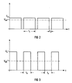
- Figure 2 shows the envelope of a modulated RF output signal.
- the pulse width (pulse duration) t 1 of each pulse of the modulation signal 17 is significantly larger than the short break with the time duration t 2 between two pulses. This results in a relatively small difference between the peak voltage U s and the effective voltage U eff of the envelope signal. Therefore, only a low coagulation depth is achieved.
- the ratio between pulse duration t3 and the pause duration t4 is chosen to be the same size, whereby a favorable coagulation effect can be achieved. It is clearly shown that with the same effective voltage U eff in FIGS. 3 and 2, the ratio to the respective peak voltage U s is different and is considerably larger in FIG. 3. A deeper coagulation is thus achieved with the HF output signal belonging to the envelope curve according to FIG. 3, without the rms value of the output power once selected having to be adjusted due to the modulation.
- the pulse repetition frequency of the modulation signal 17 is chosen to be the same in both representations in FIGS. 2 and 3, which results from the pulse rising edges which coincide in time. If necessary, the pulse repetition frequency of the modulation signal 17 generated there can also be varied via the microprocessor 2.
- the HF surgical device proposed according to the invention can be used with particular advantage in dentistry because there Among other things, there is a requirement to adapt the scab depth to biological tissue quickly and easily in order to avoid bleeding in the mouth area during the treatment.
Description
Die Erfindung betrifft ein HF-Chirurgiegerät mit einem Mikroprozessor und mit einer Vergleichsschaltung, die ein Steuersignal abgibt, das auf eine gleichgerichtete Betriebsspannung einwirkt, die ein HF-Ausgangssignal steuert, das mit einem Modulationssignal modulierbar ist.The invention relates to an HF surgical device with a microprocessor and with a comparison circuit which emits a control signal which acts on a rectified operating voltage which controls an HF output signal which can be modulated with a modulation signal.
Aus der EP-A-0 316 469 ist ein HF-Chirurgiegerät der eingangs genannten Art bekannt. Bei dem bekannten HF-Chirurgiegerät können einer Vergleichsschaltung verschiedene Sollwerte für eine HF-Ausgangsspannung zugeführt werden. Die Sollwerte können vorprogrammiert und durch Betätigen von Schaltmitteln, z.B. an einem Elektrodenhandgriff, auch aus einem Mikroprozessor abrufbar sein. Das erforderliche Vergleichssignal wird aus der HF-Ausgangsspannung gebildet, wozu ein isolierendes Bauteil, z.B. ein Transformator, und mindestens ein Spannungswandler erforderlich sind. Daher muß das HF-Ausgangssignal eine möglichst konstante Struktur haben, was bei einer Amplitudenmodulation nicht der Fall ist. Bei dem bekannten HF-Chirurgiegerät ist zu prüfen, ob das Vergleichssignal dem Spitzenwert, dem Effektivwert oder einem Mittelwert der modulierten HF-Ausgangsspannung proportional sein soll. Dementsprechend sind zusätzliche Spannungswandler erforderlich, die im Bedarfsfall vom Bediener einzuschalten sind.EP-A-0 316 469 discloses an HF surgical device of the type mentioned at the beginning. In the known HF surgical device, different setpoints for an HF output voltage can be supplied to a comparison circuit. The setpoints can be preprogrammed and activated by switching devices, e.g. on an electrode handle, can also be called up from a microprocessor. The required comparison signal is formed from the RF output voltage, for which purpose an insulating component, e.g. a transformer, and at least one voltage converter are required. The RF output signal must therefore have a structure that is as constant as possible, which is not the case with amplitude modulation. In the known HF surgical device, it is to be checked whether the comparison signal should be proportional to the peak value, the effective value or an average value of the modulated HF output voltage. Accordingly, additional voltage converters are required, which must be switched on by the operator if necessary.
Um eine tiefe Koagulation zu erreichen, wird durch die Modulation das Verhältnis der Spitzenspannung zur Effektivspannung vergrößert, wobei jedoch die effektive Ausgangsleistung weitgehend konstant bleiben muß. Durch die Amplitudenmodulation entstehen in der HF-Ausgangsspannung entsprechend der zugehörigen Hüllkurve des Modulationssignals Leistungserhöhungen bzw. Leistungsverminderungen. Die HF-Ausgangsspannung hat daher keine konstante Struktur. Folglich entsteht bei einer z.B. vom Spitzenwert der HF-Ausgangsspannung abhängigen Regelung durch die Täler ein gravierender Rückgang der verfügbaren effektiven Ausgangsleistung. Sonach ist keine befriedigende Koagulation möglich.In order to achieve deep coagulation, the ratio of the peak voltage to the effective voltage is increased by the modulation, but the effective output power must remain largely constant. The amplitude modulation results in increases or decreases in the RF output voltage in accordance with the associated envelope of the modulation signal. The RF output voltage therefore has no constant structure. Consequently, if the regulation through the valleys is dependent, for example, on the peak value of the HF output voltage, there is a serious drop in the available effective output power. As a result, satisfactory coagulation is not possible.
Der Bediener des bekannten HF-Chirurgiegerätes ist daher gezwungen, durch Umschalten auf einen anderen Spannungswandler und eine höhere Ausgangsspannung den durch die Modulation auftretenden Leistungsabfall auszugleichen. Das ist aber insofern mit Schwierigkeiten verbunden, als zwischen der Betriebsspannung und der HF-Ausgangsleistung ein nichtlinearer Zusammenhang besteht. Vor allem der weniger geübte Bediener eines HF-Chirurgiegerätes kann mit dem Auswählen und Einstellen der geeigneten Parameter schnell überfordert sein.The operator of the known HF surgical device is therefore forced to compensate for the drop in performance caused by the modulation by switching to another voltage converter and a higher output voltage. However, this is associated with difficulties in that there is a nonlinear relationship between the operating voltage and the RF output power. Especially the less experienced operator of an electrosurgical unit can quickly be overwhelmed with the selection and setting of the appropriate parameters.
Aufgabe der Erfindung ist es, ein HF-Chirurgiegerät der eingangs genannten Art anzugeben, mit dem bei geringem Bauteileaufwand im Falle einer Umschaltung auf ein moduliertes HF-Ausgangssignal eine selbsttätige, weitgehende Konstanz der effektiven Ausgangsleistung erreicht wird. Ferner sollen an das modulierte HF-Ausgangssignal Zusatzeinrichtungen, z.B. Einrichtungen zur Überwachung des Ausgangssignals, ebenfalls selbsttätig angepaßt werden.The object of the invention is to provide an HF surgical device of the type mentioned at the outset, with which an automatic, extensive constancy of the effective output power is achieved with little component expenditure in the event of a switchover to a modulated HF output signal. Furthermore, additional devices, e.g. Devices for monitoring the output signal, can also be adjusted automatically.
Diese Aufgabe wird erfindungsgemäß durch die im Anspruch angegebenen Merkmale gelöst. In den übrigen Ansprüchen sind vorteilhafte Ausgestaltungen und Weiterbildungen der Erfindung angegeben.This object is achieved by the features specified in the claim. Advantageous refinements and developments of the invention are specified in the remaining claims.
Bei der erfindungsgemäßen Ausbildung sind weder ein isolierender Transformator noch Spannungswandler zur Erzeugung eines Vergleichssignals erforderlich. Da der gemäß der Erfindung im Mikroprozessor (Kleinstrechner) gebildete Sollwert aus einem Stellsignal für die vorgewählte HF-Ausgangsleistung in Abhängigkeit von einem Modulationssignal errechnet wird, entfällt für den Bediener bei Umschaltung auf ein moduliertes HF-Ausgangssignal jegliche manuelle Anpassungstätigkeit hinsichtlich der effektiven HF-Ausgangsleistung. Der letztgenannte wesentliche Vorteil der Erfindung tritt auch bei einer Änderung des Modulationssignales, z.B. zur Veränderung der Koagulationstiefe, ein. Die Struktur des Modulationssignals ist bekannt bzw. im Mikroprozessor bestimmbar. Daher kann der Prozessor einen Sollwert erzeugen, der alle sich durch die Modulation ändernden Parameter im voraus berücksichtigt.In the embodiment according to the invention, neither an isolating transformer nor a voltage converter are required to generate a comparison signal. Since the setpoint formed according to the invention in the microprocessor (microcomputer) is a function of a control signal for the preselected RF output power is calculated from a modulation signal, the operator does not have to do any manual adjustment work with regard to the effective RF output power when switching to a modulated RF output signal. The last-mentioned essential advantage of the invention also occurs when the modulation signal changes, for example to change the depth of coagulation. The structure of the modulation signal is known or can be determined in the microprocessor. The processor can therefore generate a setpoint that takes into account all parameters that change due to the modulation.
In Ausbildung der Erfindung können mit Hilfe des Mikroprozessors aus dem Modulationssignal, das zur Einsparung eines entsprechenden Generators auch im Mikroprozessor erzeugt werden kann, weitere Stell-, Korrektur-und/oder Hilfssignale gebildet werden, die insbesondere im Falle eines modulierten HF-Ausgangssignales zur Steigerung der Genauigkeit und/oder Leistungsfähigkeit auf Zusatzeinrichtungen, wie z.B. Überwachungs-, Anzeige- und/oder Instrumentenbeleuchtungseinrichtungen, einwirken.In an embodiment of the invention, with the aid of the microprocessor, further actuating, correction and / or auxiliary signals can be formed from the modulation signal, which can also be generated in the microprocessor to save a corresponding generator, which increase in particular in the case of a modulated RF output signal the accuracy and / or performance on additional devices, such as Monitoring, display and / or instrument lighting devices act.
Weitere Vorteile und Einzelheiten der Erfindung ergeben sich aus der nachfolgenden Beschreibung eines Ausführungsbeispiels anhand der Zeichnungen und in Verbindung mit den Ansprüchen.Further advantages and details of the invention emerge from the following description of an exemplary embodiment with reference to the drawings and in conjunction with the claims.
Es zeigen:
- Figur 1 ein Prinzipschaltbild eines erfindungsgemäßen HF-Chirurgiegerätes und
- Figuren 2 und 3 Hüllkurven von unterschiedlich modulierten HF-Ausgangssignalen des erfindungsgemäßen HF-Chirurgiegerätes.
- Figure 1 is a schematic diagram of an HF surgical device according to the invention and
- Figures 2 and 3 envelopes of differently modulated RF output signals of the HF surgical device according to the invention.
In einem HF-Chirurgiegerät gemäß Figur 1 ist ein Komparator 1 ausgangsseitig mit einem Mikroprozessor 2 zu einer Vergleichsschaltung verbunden, die ein Steuersignal 4 abgibt. Das Steuersignal 4 ist ein binäres Signal mit einer Pulsfrequenz grösser oder gleich 20 kHz und mit einer über den Mikroprozessor 2 einstellbaren Pulsdauer. Das Steuersignal 4 regelt und stabilisiert über eine Steuereinrichtung, bestehend aus einem Treiber 3 und aus einem Leistungstransistor 5, eine gleichgerichtete Betriebsspannung UB eines HF-Generators 6. Der HF-Generator 6, der auch mehrstufig sein kann, erzeugt ein HF-Ausgangssignal 7, das über ein Handstück 8 mit einer Chirurgieelektrode zur Einwirkung auf biologisches Gewebe zur Verfügung steht. Da der Transistor 5 nicht linear, sondern geschaltet betrieben wird, ist eine Siebschaltung, gebildet aus einer Spule 9 und einem Kondensator 10, vorgesehen, um eine konstante Betriebsspannung UB für den HF-Generator, z.B. für dessen Endstufe, zu erzeugen. Die Betriebsspannung UB gelangt auch zum Eingang 11 des Komparators 1. Der Komparator 1 weist einen anderen Eingang 12 auf, dem über einen Digital/Analog-Wandler 13 ein im Mikroprozessor 2 digital erzeugter Sollwert 14 als Analogsignal zugeführt wird. Der Sollwert 14 wird im Mikroprozessor 2 aus einem über die Schalter 15 und 16 vorgebbaren Stellsignal zur Einstellung der HF-Ausgangsleistung und aus einem binären Modulationssignal 17 mit einer Frequenz von z.B. 200 Hz erzeugt, das den HF-Generator 6, z.B. über eine An- und Ausschaltung einer Betriebsspannung, z.B. der gesteuerten Betriebsspannung UB, moduliert.In an HF surgical device according to FIG. 1, a comparator 1 is connected on the output side to a microprocessor 2 to form a comparison circuit which emits a control signal 4. The control signal 4 is a binary signal with a pulse frequency greater or equal to 20 kHz and with a pulse duration adjustable via the microprocessor 2. The control signal 4 regulates and stabilizes a rectified operating voltage U B of an HF generator 6 via a control device consisting of a driver 3 and a power transistor 5. The HF generator 6, which can also be multi-stage, generates an HF output signal 7 , which is available via a handpiece 8 with a surgical electrode for acting on biological tissue. Since the transistor 5 is not operated linearly, but switched, a filter circuit, formed from a coil 9 and a
Eine Erhöhung oder eine Verminderung der vorwählbaren effektiven HF-Ausgangsleistung ist durch eine zeitdauerabhängige Betätigung der Schalter 15 bzw. 16 über den Mikroprozessor 2 gegeben.An increase or a decrease in the preselectable effective RF output power is given by a time-dependent actuation of the
Vorzugsweise am Handstück 8 können Schalter 18 bzw. 19 angeordnet sein, mit denen die Koagulationstiefe über den Mikroprozessor 2 kontinuierlich einstellbar ist. Dazu wird durch eine zeitdauerabhängige Betätigung der Schalter 18 bzw. 19 bei einem z.B. im Mikroprozessor erzeugten Modulationssignal 17, das aus einer Rechteckimpulsfolge bestimmter Taktfrequenz besteht, eine Einstellung der Pulsbreite t₁ bzw. t₃ der Einzelpulse vorgenommen, vergleiche dazu auch die Figuren 2 und 3.
Bauteile zur Einschaltung des Modulationssignals 17 können entfallen, wenn die Pulsbreite t₁ bzw. t₃ so groß wählbar ist, daß unter Fortfall von Pulspausen t₂ bzw. t₄ ein Dauersignal entstehen kann, wodurch der HF-Generator 6 ein konstantes (unmoduliertes) HF-Ausgangssignal abgibt. Mit dem Modulationssignal kann sonach auch der HF-Generator 6 eingeschaltet werden. Das Modulationssignal kann dem Mikrocomputer 2 auch aus einem separaten, nicht dargestellten Generator zugeführt werden, z.B. als eine gleichgerichtete, ungesiebte Wechselspannung.Components for switching on the modulation signal 17 can be omitted if the pulse width t 1 or t 3 can be selected to be so large that a continuous signal can occur with the elimination of pulse pauses t 2 or t 2, whereby the HF generator 6 emits a constant (unmodulated) HF output signal . The HF generator 6 can therefore also be switched on with the modulation signal. The modulation signal can also be supplied to the microcomputer 2 from a separate generator, not shown, e.g. as a rectified, unscreened AC voltage.
Aus dem Modulationssignal können im Mikroprozessor 2 weitere, voneinander entkoppelte Signale zur Steuerung von Funktionen im HF-Chirurgiegerät gebildet werden. Dazu kann ein weiteres Signal 22 unabhängig vom Modulationssignal 17 in der Impulsbreite durch zeitabhängiges Betätigen der Schalter 20 bzw. 21 zur Steuerung der Intensität einer Instrumentenbeleuchtung dienen.The modulation signal can be used in the microprocessor 2 to form further, decoupled signals for controlling functions in the HF surgical device. For this purpose, another
Mit einem Schalter 23 kann über den Mikroprozessor 2 der HF-Generator 6 und damit das hochfrequente Ausgangssignal ein- und ausgeschaltet werden. Der Mikroprozessor 2 kann nach Einschaltung eines Schalters 24 auch das Instrumentenlicht steuern, und zwar derart, daß nach Ausschalten des HF-Generators das Instrumentenlicht, z.B. im Handstück 8, noch für eine kurze Zeitspanne, z.B. 7 sec, weiterleuchtet.With a
Eine Überwachungseinrichtung 25 mit einem angeschlossenen Signalgeber 26 kann von einem aus dem Modulationssignal 17 im Mikroprozessor 2 gebildeten komplementären Signal 27 so gesteuert werden, daß während der Pulspausen t₂ bzw. t₄ im Modulationssignal die Überwachungseinrichtung nicht anspricht, um Fehlalarm zu vermeiden. Des weiteren kann ein derartiges komplementäres Signal 27 auch zur Korrektur einer HF-Leistungsanzeigeeinrichtung 28 im Falle eines modulierten HF-Ausgangssignals herangezogen werden. Eine Verschorfungstiefenanzeige 29 ist ebenfalls sehr günstig ohne besonderen Aufwand an steuernden Bauteilen sowohl aus dem Korrektursignal 27 als auch aus dem Modulationssignal 17 mit Hilfe des Mikroprozessors 2 realisierbar. Wenn der Überwachungseinrichtung 25 ein aus der Betriebsspannung UB abgeleitetes Analogsignal 30 zugeführt wird, kann das Binärsignal 27 auch zur Effektivwertbildung dienen.A monitoring device 25 with a connected
Figur 2 zeigt die Hüllkurve eines modulierten HF-Ausgangssignals. Die Pulsbreite (Pulsdauer) t₁ eines jeden Pulses des Modulationssignals 17 ist deutlich größer als die kurze Pause mit der Zeitdauer t₂ zwischen zwei Pulsen. Daraus resultiert eine verhältnismäßig geringe Differenz zwischen der Spitzenspannung Us und der Effektivspannung Ueff des Hüllkurvensignals. Daher wird eine nur geringe Koagulationstiefe erreicht.Figure 2 shows the envelope of a modulated RF output signal. The pulse width (pulse duration) t 1 of each pulse of the modulation signal 17 is significantly larger than the short break with the time duration t 2 between two pulses. This results in a relatively small difference between the peak voltage U s and the effective voltage U eff of the envelope signal. Therefore, only a low coagulation depth is achieved.
Gemäß Figur 3 ist das Verhältnis zwischen Pulsdauer t₃ und der Pausendauer t₄ gleich groß gewählt, wodurch eine günstige Koagulationswirkung erreichbar ist. Es ist deutlich dargestellt, daß bei gleicher Effektivspannung Ueff in den Figuren 3 und 2 das Verhältnis zur jeweiligen Spitzenspannung Us verschieden und in der Figur 3 erheblich größer ist. Mit dem zur Hüllkurve gemäß Figur 3 gehörenden HF-Ausgangssignal wird somit eine tiefere Koagulation erreicht, ohne daß der einmal gewählte Effektivwert der Ausgangsleistung aufgrund der Modulation nachgestellt werden muß.According to Figure 3, the ratio between pulse duration t₃ and the pause duration t₄ is chosen to be the same size, whereby a favorable coagulation effect can be achieved. It is clearly shown that with the same effective voltage U eff in FIGS. 3 and 2, the ratio to the respective peak voltage U s is different and is considerably larger in FIG. 3. A deeper coagulation is thus achieved with the HF output signal belonging to the envelope curve according to FIG. 3, without the rms value of the output power once selected having to be adjusted due to the modulation.
Die Pulsfolgefrequenz des Modulationssignals 17 ist bei beiden Darstellungen in den Figuren 2 und 3 gleich groß gewählt, was sich aus den zeitlich übereinstimmenden Pulsanstiegsflanken ergibt. Im Bedarfsfall kann über den Mikroprozessor 2 auch die Pulsfolgefrequenz des dort erzeugten Modulationssignals 17 variiert werden.The pulse repetition frequency of the modulation signal 17 is chosen to be the same in both representations in FIGS. 2 and 3, which results from the pulse rising edges which coincide in time. If necessary, the pulse repetition frequency of the modulation signal 17 generated there can also be varied via the microprocessor 2.
Das erfindungsgemäß vorgeschlagene HF-Chirurgiegerät ist mit besonderem Vorteil in der Zahnmedizin einsetzbar, weil dort u.a. die Forderung besteht, die Verschorfungstiefe schnell und problemlos an biologisches Gewebe anpassen zu müssen, um Blutungen im Mundbereich während der Behandlung zu vermeiden.The HF surgical device proposed according to the invention can be used with particular advantage in dentistry because there Among other things, there is a requirement to adapt the scab depth to biological tissue quickly and easily in order to avoid bleeding in the mouth area during the treatment.
Claims (8)
- HF surgery device with a differential connection (1, 2) which includes a microprocessor (2) and which emits a control signal (4) which acts on the amplitude of a rectified operating voltage (UB), which supplies a HF generator (6), the output signal of which can be modulated with a modulation signal (17), whereby the microprocessor (2) forms from the modulation signal (17) and from a specified actuating signal for the adjustment of a HF output a desired value (14) which is compared with the operating voltage (UB) in the differential connection (1, 2) for the formation of the control signal (4), whereby for each modulation depth the desired value (4) necessary for this is determined in such a way that the HF output set is kept constant.
- HF surgery device according to claim 1, where the microprocessor (2) generates the modulation signal (17) as a pulse train, the pulses of which modulate the output signal of the HF generator (6) through connection and disconnection.
- HF surgery device according to claim 2, where the microprocessor (2) generates the modulation signal (17) as a pulse train, the individual pulses of which can be adjusted to change the coagulation depth in the pulse width (t₁, t₃).
- HF surgery device according to claim 3, having a handpiece (8) which has means (15, 16; 18, 19) to control functions in the HF surgery device, where at least one set of these means (18, 19) acts by way of the microprocessor (2) on the pulse width (t₁, t₃) of the modulation signal (17) in such a way that with increasing pulse width (t₁, t₃) with the omission of pulse pauses (t₂, t₄) a continuous signal can arise.
- HF surgery device according to claim 2, where the microprocessor (2) generates the modulation signal (17) as a pulse train, from which two signals (17, 22) decoupled from one another are formed, the individual pulses of which can be adjusted independently of one another in the pulse width (t₁, t₃).
- HF surgery device according to claim 5, where the one decoupled signal forms the modulation signal (17), from which a complementary signal (27) is formed to control a monitoring device (25) and where the other decoupled signal (22) serves to illuminate the instruments.
- HF surgery device according to one of claims 1 to 7, where the differential connection is formed from the microprocessor (2) and a comparator (1) connected thereto on the output side, from the output signal of which in the microprocessor (2) the control signal (4) is generated, which acts by way of a control device (3, 5) on the rectified operating voltage (UB).
- HF surgery device according to one of claims 1 to 7, where the desired value (14) in the microprocessor (2) is digitally generated and is supplied by way of a digital-to-analog converter (13) as analog signal to the one input (12) of the differential connection (1, 2), the other input (11) of which is connected to the controlled operating voltage (UB).
Applications Claiming Priority (2)
| Application Number | Priority Date | Filing Date | Title |
|---|---|---|---|
| DE4009819A DE4009819C2 (en) | 1990-03-27 | 1990-03-27 | HF surgery device |
| DE4009819 | 1990-03-27 |
Publications (2)
| Publication Number | Publication Date |
|---|---|
| EP0448798A1 EP0448798A1 (en) | 1991-10-02 |
| EP0448798B1 true EP0448798B1 (en) | 1995-07-26 |
Family
ID=6403161
Family Applications (1)
| Application Number | Title | Priority Date | Filing Date |
|---|---|---|---|
| EP90123741A Expired - Lifetime EP0448798B1 (en) | 1990-03-27 | 1990-12-10 | Electrosurgical unit |
Country Status (4)
| Country | Link |
|---|---|
| US (1) | US5167660A (en) |
| EP (1) | EP0448798B1 (en) |
| JP (1) | JPH084010Y2 (en) |
| DE (2) | DE4009819C2 (en) |
Cited By (12)
| Publication number | Priority date | Publication date | Assignee | Title |
|---|---|---|---|---|
| US5944715A (en) | 1996-06-20 | 1999-08-31 | Gyrus Medical Limited | Electrosurgical instrument |
| US6004319A (en) | 1995-06-23 | 1999-12-21 | Gyrus Medical Limited | Electrosurgical instrument |
| US6013076A (en) | 1996-01-09 | 2000-01-11 | Gyrus Medical Limited | Electrosurgical instrument |
| US6015406A (en) | 1996-01-09 | 2000-01-18 | Gyrus Medical Limited | Electrosurgical instrument |
| US6027501A (en) | 1995-06-23 | 2000-02-22 | Gyrus Medical Limited | Electrosurgical instrument |
| US6090106A (en) | 1996-01-09 | 2000-07-18 | Gyrus Medical Limited | Electrosurgical instrument |
| US6093186A (en) | 1996-12-20 | 2000-07-25 | Gyrus Medical Limited | Electrosurgical generator and system |
| US6210405B1 (en) | 1996-06-20 | 2001-04-03 | Gyrus Medical Limited | Under water treatment |
| US6261286B1 (en) | 1995-06-23 | 2001-07-17 | Gyrus Medical Limited | Electrosurgical generator and system |
| US6277114B1 (en) | 1998-04-03 | 2001-08-21 | Gyrus Medical Limited | Electrode assembly for an electrosurical instrument |
| US6565561B1 (en) | 1996-06-20 | 2003-05-20 | Cyrus Medical Limited | Electrosurgical instrument |
| US6780180B1 (en) | 1995-06-23 | 2004-08-24 | Gyrus Medical Limited | Electrosurgical instrument |
Families Citing this family (32)
| Publication number | Priority date | Publication date | Assignee | Title |
|---|---|---|---|---|
| DE4126608A1 (en) * | 1991-08-12 | 1993-02-18 | Fastenmeier Karl | ARRANGEMENT FOR CUTTING ORGANIC TISSUE WITH HIGH-FREQUENCY CURRENT |
| US5713896A (en) * | 1991-11-01 | 1998-02-03 | Medical Scientific, Inc. | Impedance feedback electrosurgical system |
| US6053172A (en) * | 1995-06-07 | 2000-04-25 | Arthrocare Corporation | Systems and methods for electrosurgical sinus surgery |
| US6063079A (en) | 1995-06-07 | 2000-05-16 | Arthrocare Corporation | Methods for electrosurgical treatment of turbinates |
| GB9204217D0 (en) * | 1992-02-27 | 1992-04-08 | Goble Nigel M | Cauterising apparatus |
| US5540681A (en) * | 1992-04-10 | 1996-07-30 | Medtronic Cardiorhythm | Method and system for radiofrequency ablation of tissue |
| US5300068A (en) * | 1992-04-21 | 1994-04-05 | St. Jude Medical, Inc. | Electrosurgical apparatus |
| DE4217999C2 (en) * | 1992-05-31 | 1999-11-18 | Erbe Elektromedizin | High frequency surgical device |
| US5584830A (en) * | 1994-03-30 | 1996-12-17 | Medtronic Cardiorhythm | Method and system for radiofrequency ablation of cardiac tissue |
| AU4012595A (en) * | 1994-10-28 | 1996-05-31 | Chiron Vision Corporation | Bipolar electrosurgical apparatus |
| US5707369A (en) * | 1995-04-24 | 1998-01-13 | Ethicon Endo-Surgery, Inc. | Temperature feedback monitor for hemostatic surgical instrument |
| EP0836433A1 (en) * | 1995-06-06 | 1998-04-22 | Valleylab, Inc. | Digital waveform generation for electrosurgical generators |
| US5792138A (en) * | 1996-02-22 | 1998-08-11 | Apollo Camera, Llc | Cordless bipolar electrocautery unit with automatic power control |
| US6066139A (en) * | 1996-05-14 | 2000-05-23 | Sherwood Services Ag | Apparatus and method for sterilization and embolization |
| US5817091A (en) * | 1997-05-20 | 1998-10-06 | Medical Scientific, Inc. | Electrosurgical device having a visible indicator |
| US7066933B2 (en) * | 2000-08-08 | 2006-06-27 | Erbe Elektromedizin Gmbh | High-frequency generator for performing high-frequency surgery having adjustable power limitation, and method for controlling the power limitation |
| DE10046592C2 (en) * | 2000-09-20 | 2002-12-05 | Erbe Elektromedizin | Device for high-frequency surgery |
| US6942660B2 (en) * | 2002-11-19 | 2005-09-13 | Conmed Corporation | Electrosurgical generator and method with multiple semi-autonomously executable functions |
| US6939347B2 (en) * | 2002-11-19 | 2005-09-06 | Conmed Corporation | Electrosurgical generator and method with voltage and frequency regulated high-voltage current mode power supply |
| JP3548765B1 (en) * | 2003-03-11 | 2004-07-28 | オムロン株式会社 | Maximum power tracking controller |
| US7491200B2 (en) | 2004-03-26 | 2009-02-17 | Arthrocare Corporation | Method for treating obstructive sleep disorder includes removing tissue from base of tongue |
| US7892230B2 (en) | 2004-06-24 | 2011-02-22 | Arthrocare Corporation | Electrosurgical device having planar vertical electrode and related methods |
| US8717181B2 (en) | 2010-07-29 | 2014-05-06 | Hill-Rom Services, Inc. | Bed exit alert silence with automatic re-enable |
| US10448992B2 (en) | 2010-10-22 | 2019-10-22 | Arthrocare Corporation | Electrosurgical system with device specific operational parameters |
| US8747401B2 (en) | 2011-01-20 | 2014-06-10 | Arthrocare Corporation | Systems and methods for turbinate reduction |
| US9168082B2 (en) | 2011-02-09 | 2015-10-27 | Arthrocare Corporation | Fine dissection electrosurgical device |
| US9271784B2 (en) | 2011-02-09 | 2016-03-01 | Arthrocare Corporation | Fine dissection electrosurgical device |
| US9011428B2 (en) | 2011-03-02 | 2015-04-21 | Arthrocare Corporation | Electrosurgical device with internal digestor electrode |
| US9788882B2 (en) | 2011-09-08 | 2017-10-17 | Arthrocare Corporation | Plasma bipolar forceps |
| US9254166B2 (en) | 2013-01-17 | 2016-02-09 | Arthrocare Corporation | Systems and methods for turbinate reduction |
| US11446078B2 (en) | 2015-07-20 | 2022-09-20 | Megadyne Medical Products, Inc. | Electrosurgical wave generator |
| EP4124310B1 (en) | 2021-07-26 | 2023-10-18 | Erbe Elektromedizin GmbH | Generator with feedback device |
Family Cites Families (17)
| Publication number | Priority date | Publication date | Assignee | Title |
|---|---|---|---|---|
| US3812858A (en) * | 1972-10-24 | 1974-05-28 | Sybron Corp | Dental electrosurgical unit |
| FR2517955A1 (en) * | 1981-12-14 | 1983-06-17 | Siab | Key panel and memory control for electric scalpel - permits touch sensitive adjustment of mark-to-space ratio and amplitude of supply pulses under programmed control |
| FR2536924A1 (en) * | 1982-11-25 | 1984-06-01 | Courtois Michele | ELECTRO-SURGERY DEVICE COMPRISING A GENERATOR OF VERY STRAIGHT FRONT RECTANGULAR SLOTS |
| US4590934A (en) * | 1983-05-18 | 1986-05-27 | Jerry L. Malis | Bipolar cutter/coagulator |
| US4658819A (en) * | 1983-09-13 | 1987-04-21 | Valleylab, Inc. | Electrosurgical generator |
| GB8401887D0 (en) * | 1984-01-25 | 1984-02-29 | Matburn Holdings Ltd | Electrosurgical unit |
| US4574801A (en) * | 1984-02-29 | 1986-03-11 | Aspen Laboratories, Inc. | Electrosurgical unit with regulated output |
| US4727874A (en) * | 1984-09-10 | 1988-03-01 | C. R. Bard, Inc. | Electrosurgical generator with high-frequency pulse width modulated feedback power control |
| US4658820A (en) * | 1985-02-22 | 1987-04-21 | Valleylab, Inc. | Electrosurgical generator with improved circuitry for generating RF drive pulse trains |
| US4739759A (en) * | 1985-02-26 | 1988-04-26 | Concept, Inc. | Microprocessor controlled electrosurgical generator |
| EP0219568B1 (en) * | 1985-10-23 | 1989-10-11 | Erbe Elektromedizin GmbH. | High-frequency surgical apparatus |
| DE3751452D1 (en) * | 1987-11-17 | 1995-09-14 | Erbe Elektromedizin | High-frequency surgical device for cutting and / or coagulating biological tissue. |
| US4961739A (en) * | 1988-03-07 | 1990-10-09 | Aspen Labatories, Inc. | Waveform generator for electrosurgical apparatus |
| EP0336742A3 (en) * | 1988-04-08 | 1990-05-16 | Bristol-Myers Company | Method and apparatus for the calibration of electrosurgical apparatus |
| DE3830193A1 (en) * | 1988-09-06 | 1990-03-15 | Hubmann Max | Method and electrical circuit for determining and/or limiting a high-frequency energy supplied with a catheter |
| JP2542058B2 (en) * | 1988-10-07 | 1996-10-09 | オリンパス光学工業株式会社 | High frequency electrosurgical unit |
| US4961047A (en) * | 1988-11-10 | 1990-10-02 | Smiths Industries Public Limited Company | Electrical power control apparatus and methods |
-
1990
- 1990-03-27 DE DE4009819A patent/DE4009819C2/en not_active Expired - Fee Related
- 1990-12-10 EP EP90123741A patent/EP0448798B1/en not_active Expired - Lifetime
- 1990-12-10 DE DE59009443T patent/DE59009443D1/en not_active Expired - Fee Related
-
1991
- 1991-03-12 US US07/668,113 patent/US5167660A/en not_active Expired - Fee Related
- 1991-03-25 JP JP1991026248U patent/JPH084010Y2/en not_active Expired - Fee Related
Cited By (18)
| Publication number | Priority date | Publication date | Assignee | Title |
|---|---|---|---|---|
| US6174308B1 (en) | 1995-06-23 | 2001-01-16 | Gyrus Medical Limited | Electrosurgical instrument |
| US6364877B1 (en) | 1995-06-23 | 2002-04-02 | Gyrus Medical Limited | Electrosurgical generator and system |
| US6416509B1 (en) | 1995-06-23 | 2002-07-09 | Gyrus Medical Limited | Electrosurgical generator and system |
| US6004319A (en) | 1995-06-23 | 1999-12-21 | Gyrus Medical Limited | Electrosurgical instrument |
| US6027501A (en) | 1995-06-23 | 2000-02-22 | Gyrus Medical Limited | Electrosurgical instrument |
| US6056746A (en) | 1995-06-23 | 2000-05-02 | Gyrus Medical Limited | Electrosurgical instrument |
| US6261286B1 (en) | 1995-06-23 | 2001-07-17 | Gyrus Medical Limited | Electrosurgical generator and system |
| US6780180B1 (en) | 1995-06-23 | 2004-08-24 | Gyrus Medical Limited | Electrosurgical instrument |
| US6013076A (en) | 1996-01-09 | 2000-01-11 | Gyrus Medical Limited | Electrosurgical instrument |
| US6015406A (en) | 1996-01-09 | 2000-01-18 | Gyrus Medical Limited | Electrosurgical instrument |
| US6090106A (en) | 1996-01-09 | 2000-07-18 | Gyrus Medical Limited | Electrosurgical instrument |
| US6234178B1 (en) | 1996-01-09 | 2001-05-22 | Gyrus Medical Limited | Electrosurgical instrument |
| US6210405B1 (en) | 1996-06-20 | 2001-04-03 | Gyrus Medical Limited | Under water treatment |
| US6482202B1 (en) | 1996-06-20 | 2002-11-19 | Gyrus Medical Limited | Under water treatment |
| US6565561B1 (en) | 1996-06-20 | 2003-05-20 | Cyrus Medical Limited | Electrosurgical instrument |
| US5944715A (en) | 1996-06-20 | 1999-08-31 | Gyrus Medical Limited | Electrosurgical instrument |
| US6093186A (en) | 1996-12-20 | 2000-07-25 | Gyrus Medical Limited | Electrosurgical generator and system |
| US6277114B1 (en) | 1998-04-03 | 2001-08-21 | Gyrus Medical Limited | Electrode assembly for an electrosurical instrument |
Also Published As
| Publication number | Publication date |
|---|---|
| US5167660A (en) | 1992-12-01 |
| EP0448798A1 (en) | 1991-10-02 |
| DE59009443D1 (en) | 1995-08-31 |
| JPH0488921U (en) | 1992-08-03 |
| JPH084010Y2 (en) | 1996-02-07 |
| DE4009819C2 (en) | 1994-10-06 |
| DE4009819A1 (en) | 1991-10-02 |
Similar Documents
| Publication | Publication Date | Title |
|---|---|---|
| EP0448798B1 (en) | Electrosurgical unit | |
| EP0653192B1 (en) | High frequence surgical device to cut and/or coagulate biological tissues | |
| DE60015881T2 (en) | Low voltage electrosurgical device | |
| DE2363917C2 (en) | Electrically operated surgical knife | |
| DE3531576C2 (en) | Electrosurgery generator | |
| DE602004009293T2 (en) | ELECTRO-SURGICAL GENERATOR AND SYSTEM | |
| DE3622430C2 (en) | ||
| DE3502193A1 (en) | ELECTROSURGICAL DEVICE | |
| WO2002011634A1 (en) | High-frequency generator for performing high-frequency surgery having adjustable power limitation, and method for controlling the power limitation | |
| EP0925761A1 (en) | Method for the use of an ablation device and high frequency tissue ablating device therefore | |
| WO2002100283A1 (en) | Electrosurgical device | |
| DE69733955T2 (en) | CONTROL SYSTEM FOR ACOUSTIC DETECTORS | |
| DE4400210A1 (en) | Method and device for operating a generator for the HF energy supply of an ultrasonic transducer | |
| EP0709065A1 (en) | Electrosurgical unit and process for its use | |
| DE3212706A1 (en) | MEDICAL STIMULATOR AND STIMULATION METHOD | |
| EP2393443A1 (en) | Hf surgery device | |
| EP1095543B1 (en) | Ballast for at least one gas discharge lamp and method for operating such a ballast | |
| DE19516052A1 (en) | Method for operating a high-pressure gas discharge lamp and circuit arrangement for carrying out the method | |
| EP0557599A1 (en) | Method of controlling a digital pulse step modulator PSM | |
| EP3334359A1 (en) | Method and device for controlling the energy supply to a medical instrument | |
| EP2676624B1 (en) | High frequency surgical device | |
| WO2008015204A1 (en) | Method for operating an illumination system with sequential color filtering and a high pressure discharge lamp | |
| DE10064965B4 (en) | Medical device for applying electrical energy to a patient | |
| DE3340891C2 (en) | ||
| EP0217011A1 (en) | Universal electrotherapeutical apparatus |
Legal Events
| Date | Code | Title | Description |
|---|---|---|---|
| PUAI | Public reference made under article 153(3) epc to a published international application that has entered the european phase |
Free format text: ORIGINAL CODE: 0009012 |
|
| 17P | Request for examination filed |
Effective date: 19901210 |
|
| AK | Designated contracting states |
Kind code of ref document: A1 Designated state(s): DE FR GB IT SE |
|
| 17Q | First examination report despatched |
Effective date: 19940127 |
|
| GRAA | (expected) grant |
Free format text: ORIGINAL CODE: 0009210 |
|
| AK | Designated contracting states |
Kind code of ref document: B1 Designated state(s): DE FR GB IT SE |
|
| PG25 | Lapsed in a contracting state [announced via postgrant information from national office to epo] |
Ref country code: GB Effective date: 19950726 |
|
| REF | Corresponds to: |
Ref document number: 59009443 Country of ref document: DE Date of ref document: 19950831 |
|
| ITF | It: translation for a ep patent filed |
Owner name: STUDIO JAUMANN |
|
| ET | Fr: translation filed | ||
| GBV | Gb: ep patent (uk) treated as always having been void in accordance with gb section 77(7)/1977 [no translation filed] |
Effective date: 19950726 |
|
| PLBQ | Unpublished change to opponent data |
Free format text: ORIGINAL CODE: EPIDOS OPPO |
|
| PLBI | Opposition filed |
Free format text: ORIGINAL CODE: 0009260 |
|
| PLBF | Reply of patent proprietor to notice(s) of opposition |
Free format text: ORIGINAL CODE: EPIDOS OBSO |
|
| 26 | Opposition filed |
Opponent name: STORZ ENDOSKOP GMBH Effective date: 19960426 |
|
| PLBF | Reply of patent proprietor to notice(s) of opposition |
Free format text: ORIGINAL CODE: EPIDOS OBSO |
|
| PLBL | Opposition procedure terminated |
Free format text: ORIGINAL CODE: EPIDOS OPPC |
|
| PLBM | Termination of opposition procedure: date of legal effect published |
Free format text: ORIGINAL CODE: 0009276 |
|
| STAA | Information on the status of an ep patent application or granted ep patent |
Free format text: STATUS: OPPOSITION PROCEDURE CLOSED |
|
| 27C | Opposition proceedings terminated |
Effective date: 19970506 |
|
| REG | Reference to a national code |
Ref country code: FR Ref legal event code: TP |
|
| PGFP | Annual fee paid to national office [announced via postgrant information from national office to epo] |
Ref country code: SE Payment date: 20081217 Year of fee payment: 19 Ref country code: IT Payment date: 20081219 Year of fee payment: 19 |
|
| PGFP | Annual fee paid to national office [announced via postgrant information from national office to epo] |
Ref country code: FR Payment date: 20081211 Year of fee payment: 19 |
|
| PGFP | Annual fee paid to national office [announced via postgrant information from national office to epo] |
Ref country code: DE Payment date: 20081230 Year of fee payment: 19 |
|
| EUG | Se: european patent has lapsed | ||
| REG | Reference to a national code |
Ref country code: FR Ref legal event code: ST Effective date: 20100831 |
|
| PG25 | Lapsed in a contracting state [announced via postgrant information from national office to epo] |
Ref country code: FR Free format text: LAPSE BECAUSE OF NON-PAYMENT OF DUE FEES Effective date: 20091231 |
|
| PG25 | Lapsed in a contracting state [announced via postgrant information from national office to epo] |
Ref country code: DE Free format text: LAPSE BECAUSE OF NON-PAYMENT OF DUE FEES Effective date: 20100701 |
|
| PG25 | Lapsed in a contracting state [announced via postgrant information from national office to epo] |
Ref country code: IT Free format text: LAPSE BECAUSE OF NON-PAYMENT OF DUE FEES Effective date: 20091210 |
|
| PG25 | Lapsed in a contracting state [announced via postgrant information from national office to epo] |
Ref country code: SE Free format text: LAPSE BECAUSE OF NON-PAYMENT OF DUE FEES Effective date: 20091211 |