EP0447863A1 - Undercarriage for containers, appliances etc. - Google Patents
Undercarriage for containers, appliances etc. Download PDFInfo
- Publication number
- EP0447863A1 EP0447863A1 EP91103168A EP91103168A EP0447863A1 EP 0447863 A1 EP0447863 A1 EP 0447863A1 EP 91103168 A EP91103168 A EP 91103168A EP 91103168 A EP91103168 A EP 91103168A EP 0447863 A1 EP0447863 A1 EP 0447863A1
- Authority
- EP
- European Patent Office
- Prior art keywords
- lever
- bearing
- roller
- rocker
- push rod
- Prior art date
- Legal status (The legal status is an assumption and is not a legal conclusion. Google has not performed a legal analysis and makes no representation as to the accuracy of the status listed.)
- Withdrawn
Links
Images


Classifications
-
- B—PERFORMING OPERATIONS; TRANSPORTING
- B62—LAND VEHICLES FOR TRAVELLING OTHERWISE THAN ON RAILS
- B62B—HAND-PROPELLED VEHICLES, e.g. HAND CARTS OR PERAMBULATORS; SLEDGES
- B62B5/00—Accessories or details specially adapted for hand carts
- B62B5/04—Braking mechanisms; Locking devices against movement
- B62B5/0457—Braking mechanisms; Locking devices against movement by locking in a braking position
- B62B5/0461—Braking mechanisms; Locking devices against movement by locking in a braking position with positive engagement
Definitions
- the invention relates to a chassis for transport containers, apparatus or the like.
- a base plate and - mounted thereon at least two rollers and a locking device for a blocking device for at least the rotational movement of the wheels of the rollers
- the locking device each having at least one locking lever and one Has release levers which are coupled to one another via a linkage arrangement and are operatively connected to tappet-side tappets as part of the blocking device, whereby on a rocker arm pivotably mounted on the base plate, on the one hand, handlebars connected to the levers, and on the other hand, push rods engage with which at least indirectly wedge surfaces for adjusting the tappets are connected are.
- this is intended for a landing gear for serving trolleys that serve as mobile containers in commercial aircraft for storing food and beverages that are issued to the passengers, and then for collecting the empty containers and packaging.
- Such transport containers are called “trolleys”.
- An undercarriage for trolleys has become known through obvious prior use, which is very complicated in the construction of its locking device and blocking device.
- the present invention is based on such a chassis.
- the push rods which are in turn articulated on the rocker, are coupled with adjustable brackets mounted in brackets.
- These adjusting brackets which like their bearings consist of complex light-alloy die-cast parts, act on stroke-adjusting rods in the bearing cheeks of the bearings with respect to the height.
- the object of the invention is therefore to provide a chassis of the type outlined in the preamble of claim 1, which is considerably simplified in its construction and in which the blocking device always acts reliably for each roller to be blocked.
- the design of the undercarriage should also allow a simple arrangement of a swivel lock of the castors if necessary.
- the invention solves this problem primarily and essentially in that the push rods directly are guided from the rocker to the rollers and are provided with the wedge surfaces that are supported on the tappets by pressure.
- the push rods are guided directly, that is to say in short ways, directly from the rocker to the respective roller.
- the wedge surfaces previously located on the rotating bodies are now arranged on the push rods and serve for the direct direct action on the tappets as the components of the blocking device for at least one wheel of at least one steering roller of the undercarriage. In general, however, at least one wheel of each of a total of four castors located on the chassis is blocked.
- each push rod generally has a wedge surface that adjusts the ram. Because there are only a few interconnected parts, there is less overall play and consequently a more precise and low-wear adjustment mechanism. Of course, this also results in a considerably simplified and quicker installation of the entire undercarriage.
- each push rod each pointing from the rocker to a roller, preferably rest in a pivot bearing, which is preferably on a plate-like one Console is designed for the mounting plate of a roller.
- the end of each push rod pointing from the rocker to a roller can be overlapped by the mounting plate of the associated roller, whereby the connecting rod is held captive with respect to the base plate.
- At least one of the push rods carries an inhibiting shoe which blocks the pivoting movement of the associated roller and which presses against the roller support part when the tappet is depressed. Since the push rod is not adjusted transversely to the floor, but parallel to the floor in accordance with the invention, a restraint shoe which is fastened to the push rod and can therefore also be adjusted parallel to the floor can be arranged without further ado, so that both the wheel brake and the swivel lock on the castor take effect simultaneously can. This does not require any significant additional design effort.
- Each push rod is preferably made of plastic, and the wedge surface is integrally formed on it.
- the handlebars have web-like drivers on which the levers are each supported with claw-like actuation projections in a push-fit or pull-fit manner.
- the handlebars were previously coupled to the respective lever by means of a cotter-pin connection. It is particularly simple if the drivers on the handlebars and the actuating projections on the levers are each made of the same material and in one piece.
- the common bearing axis for the set lever and the release lever is provided with at least two axially spaced jacket projections, of which the axially outer non-rotatably in a keyhole-like notch one of the axle bearing cheeks of a lever bearing bracket and the axially inside one of the two levers is axially supported in a stepped bore, the axle bearings of the two levers being sleeve-shaped and complementing each other in their overall length to a dimension that, taking into account the required swivel movement play on the bearing axis, the clear internal dimension between the axle bearing cheeks of the levers - Storage console corresponds.
- levers and their storage are in addition to the levers themselves and the lever bracket required anyway only this specially designed bearing axis is required.
- Distance bushings and sleeves as well as washers and split pins to secure the bearing axis on the lever bearing bracket, as they were previously required, are no longer required.
- the levers are assembled without tools or external means by simply bayonet-like insertion of the bearing axis into the bearing cheeks of the lever-bearing bracket and insertion through a similar keyhole in a bearing area of one of the two levers.
- a base plate of a transport container which can be rolled with the aid of a chassis designated as a whole by 11 is designated by 10.
- the undercarriage 11 comprises four twin casters 12 designed as swivel castors, of which a pair is shown in FIGS. 1 and 2. They are each screwed onto a plate-like console 15 by means of a mounting plate 13 and screws 14, which in turn is fastened to the base plate 10.
- a plate-like rocker arm 16 is pivotably arranged in a plane parallel to the base by means of an axis 17.
- two link levers - hereinafter referred to as links 18 and 19 - are coupled to it.
- Each link 18, 19 has a key-like extension 20 which fits into a keyhole-like recess 21 of the rocker 16. After insertion, each link 18, 19 is pivoted into the intended position shown in FIGS. 1 and 2, in which it is captively attached to the rocker by means of a locking bar-like grip.
- the handlebar 18 is coupled to a lever 22 in a plane parallel to the floor and, analogously, the handlebar 19 is coupled to a lever 23 arranged next to it.
- the lever 23 is the locking lever
- the lever 22 is the release lever for the blocking device for the wheels 24, 25 of the rollers 12 described in detail below.
- the two levers 22 and 23 are pivotally mounted in a top view U-shaped lever bearing bracket 26 on a bearing axis 27 which is screwed to the base plate 10 by means of screws 28. Besides the screws 14 and the bearing screw 17 for the rocker 16, these are the only ones of the entire undercarriage.
- each push rod 29 corresponding to the number of rollers 12 are articulated in a radially more external arrangement than that of the links 18 and 19.
- the free ends of each push rod 29 pointing away from the rocker 16 are pivotally mounted in pivot bearings 30 of the brackets 15.
- the pivot bearings 30 are formed in the brackets 15 as pockets open towards the axis 17.
- Each push rod 29 extends outward from the rocker 16 substantially in the direction of the pivot axis S of each of the four steering rollers 12.
- each push rod 29 has a wedge surface 31, which points downward from the base plate 10 to the respective roller 12 and pressurizes a plunger 32, which centrally in the castor bearing 33 is vertically adjustable.
- Each tappet 32 is in motion-coupled connection via an arm 34 to a wheel brake body 35, the external toothing 36 of which is intended for engagement in a counter toothing 37 on a wheel 25. In the event of braking intervention (FIG. 3), this wheel 25 is thus locked in rotation.
- This wheel braking or locking device is also the subject of DE-GM 88 10 731 by the applicant, to which reference is made with regard to structural details.
- each tappet 32 contacts the associated push rod 29 in a pressure-locking manner in the region of its wedge surface 31 or a runner thereof (FIG. 4), the tappet 32 is in an upper position which corresponds to the wheel position not braked. If the rocker arm 16 is now rotated counterclockwise in the direction of the arrow 38 by actuating the locking lever 23, starting from FIGS. 1 and 4, all four push rods 29 are advanced. Their respective wedge surface 31 pushes onto the tappet 32 and presses it downward into the braking position corresponding to FIGS. 2 and 3.
- each push rod 29 there is also an inhibiting shoe 39, which consists of an entropy-elastic material, in particular rubber or rubber-elastic plastic, and which, in the braking position, presses against the back bearing 40 of the associated roller 12, which is thereby prevented from pivoting about its pivot axis S, which coincides with the longitudinal axis of the plunger 32.
- the brake is designed on the one hand as a rotary block for at least one wheel 25 and at the same time as a swivel block for each swivel castor 12.
- each push rod 29 consisting of a molded plastic part is held directly on the surface of the base plate 10 and is held captively in place by the push rod being overlapped by the mounting plate 13 of the associated steering roller 12.
- the push rod 29 is always on the upper end face of the plunger 32. The coupling of each end of the push rod 29 facing away from the castors 12 with the rocker 16 is simply achieved by the rocker 16 engaging with a dome recess 41 over a corresponding circular coupling pin 42 at the end of the push rod 29.
- each link 18 and 19 pass through a window 43 of the central web 44 of the lever bearing bracket 26 on their way from the rocker 16 to the respectively associated lever 22 or 23.
- each link has a web - or rib-like driver 45, with which the lever 22 cooperates in a one-sided manner by means of an extension 46 and the lever 23 by means of two extensions 47, 48, which form a claw, in a manner which is interlocking and pressure-locking.
- the arrangement is such that each lever 22, 23 on the associated one Handlebar 18 or 19 pulls when he is stepped on.
- the direction of kick for the lever 22 is designated by 49 and that for the lever 23 by 50.
- Both the two links 18 and 19 and the two levers 22 and 23 are each in turn one-piece plastic injection molded parts.
- each of the two nebulae 22 and 23 is seated on the bearing axis 27 by means of sleeve-like axle bearings 51 and 52, respectively.
- This has axially spaced and paired projections 53 and 54. These are essentially in the form of ribs tangential compression of the material of the axis 27 is formed.
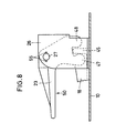
- the axially outer jacket projections 53 engage in the manner of key beards in adapted keyhole-shaped gaps 55 (FIG. 8) of one of the two axle bearing cheeks 56 of the lever bearing bracket 26.
- the other pair of projections 54 sits in a circular receptacle 57 which is formed within the bearing sleeve 52 of the lever 23.
- the bearing axis 27 is rotatably held by the positive engagement of the jacket projections 53 in the axle bearing cheek 56, while the lever 23 can pivot relative to the fixed axis 27. So that the bearing axis and lever 23 can be plugged together, the bearing bore of the mist 23 also has matching “keyholes” 63 (FIG. 7) in an arrangement that is offset circumferentially from the operating position.
- the two sleeve-shaped bearing sections 51 and 52 of the two levers 22 and 23 directly adjoin one another and have an overall length which is essentially corresponds to the clear inner width between the two legs 56 and 58 of the bracket 26.
- a leg return spring 59 is mounted on a sleeve section 51a of the lever 22, one leg 60 of which is supported in a press-fit manner under an extension 62 of the mist 22 and the other leg 61 of which rests under spring pressure on the mist bearing bracket 26 (FIG. 5).
- the locking lever 23 is depressed (arrow 50) swivels - as stated - the rocker 16 in the circumferential direction 38 and pushes the push rods 29 into the blocking position.
- the handlebar 18 is simultaneously pulled away from its associated fog 22 in the direction of the center of the plate.
- the release lever 22 is conveyed into the end position shown in FIG. 5.
- this lever 22 is depressed (arrow 49), by means of which the extension 18 pulls the handlebar 18 to the edge of the base plate 10.
- the release lever according to FIG. 5 jumps back into its favorable starting position for later actuation.
- the other handlebar 19 is pulled towards the middle of the plate. This has the consequence that the locking lever 50 is conveyed back from its position corresponding to the blocking position according to FIG. 7 into the position shown in FIG. 8, in which it can be actuated again by stepping in the direction of the arrow 50.
- each push rod 29 forms a toggle lever arrangement with the rocker 16, one toggle lever being formed by the push rod 29 itself, the other toggle lever by the connection between the pivot pins 17 and 42 and the knee coincides with the pivot pin 42.
- the blocking position according to FIG. 2 is distinguished with respect to the four toggle lever arrangements by their slight over-center position, so that the braking or blocking position is automatically secured.
- Another advantage of the toggle arrangement consists in the low actuating force of the locking lever 23 that has to be applied.
- the toggle lever blocking by depressing the release lever 22 is also easily possible with little effort.
- the blocking shoes 39 designed as elastic cushions also act to compensate for tolerances and hold the toggle lever arrangement under non-positive tension.
Abstract
Description
Die Erfindung bezieht sich auf ein Fahrwerk für Transportbehälter, Apparate od. dgl. mit einer Bodenplatte und - daran montiert - wenigstens zwei Laufrollen und einer Ferstellvorrichtung für eine Blockiereinrichtung für zumindest die Drehbewegung der Räder der Laufrollen, wobei die Feststellvorrichtung je wenigstens einen Festellhebel und einen Lösehebel aufweist, die über eine Gestängeanordnung miteinander gekuppelt und mit laufrollenseitigen Stößeln als Bestandteil der Blockiereinrichtung wirkverbunden sind, wobei an einer an der Bodenplatte schwenkbar gelagerten Schwinge einerseits mit den Hebeln verbundene Lenker und andererseits Schubstangen angreifen, mit denen mindestens mittelbar Keilflächen zur Verstellung der Stößel verbunden sind.The invention relates to a chassis for transport containers, apparatus or the like. With a base plate and - mounted thereon - at least two rollers and a locking device for a blocking device for at least the rotational movement of the wheels of the rollers, the locking device each having at least one locking lever and one Has release levers which are coupled to one another via a linkage arrangement and are operatively connected to tappet-side tappets as part of the blocking device, whereby on a rocker arm pivotably mounted on the base plate, on the one hand, handlebars connected to the levers, and on the other hand, push rods engage with which at least indirectly wedge surfaces for adjusting the tappets are connected are.
Insbesondere ist hierbei an ein Fahrwerk für Servierwagen gedacht, die in Verkehrsflugzeugen als fahrbare Behälter zur Bevorratung von Speisen und Getränken dienen, die an die Passagiere ausgegeben werden, sowie danach zum Einsammeln der leeren Gefäße und Verpackungen. Man nennt solche Transportbehälter "Trolleys". Durch offenkundige Vorbenutzung ist ein Fahrwerk für Trolleys bekanntgeworden, welches in der Konstruktion seiner Feststellvorrichtung und Blockiereinrichtung sehr kompliziert ist. Entsprechend den Merkmalen des Oberbegriffs des Anspruches 1 geht die vorliegende Erfindung von einem solchen Fahrwerk aus. Dabei sind die an der Schwinge ihrerseits gelenkig gelagerten Schubstangen mit drehbar in Konsolen gelagerten Verstellböcken gekuppelt. Diese Verstellböcke, die wie ihre Lager aus aufwendigen Leichtmetalldruckgußteilen bestehen, wirken auf in Lagerwangen der Lager bezüglich des Bodens höhenverstellbaren weiteren Stangen hubverstellend ein. Die Enden dieser Stangen, die im übrigen zur Abstützung auf den Keilflächen noch mit zusätzlichen Hülsen versehen sind, beaufschlagen die in den Laufrollen angebrachten, die Bremsung der Räder bewirkenden Stößel. Abgesehen von dem hier getriebenen konstruktiven Aufwand ist die Anordnung, auch aufgrund der Vielzahl der miteinander in Bewegungszuordnung befindlichen Einzelteile, relativ labil. So sind insbesondere die zusätzlichen Betätigungsstangen für die Stößel gegen Verkippung nicht gesichert. Die Folge davon kann sein, daß eine der beiden jeweils durch eine solche Stange blockierbetätigten Laufrollen nicht hinreichend gebremst wird. Eine Blockierung der Schwenkbewegung des Rollentragteils ist - jedenfalls mit vertretbarem Aufwand - nicht möglich.In particular, this is intended for a landing gear for serving trolleys that serve as mobile containers in commercial aircraft for storing food and beverages that are issued to the passengers, and then for collecting the empty containers and packaging. Such transport containers are called "trolleys". An undercarriage for trolleys has become known through obvious prior use, which is very complicated in the construction of its locking device and blocking device. According to the features of the preamble of
Aufgabe der Erfindung ist es folglich, ein Fahrwerk der im Oberbegriff des Anspruches 1 näher umrissenen Art verfügbar zu machen, welches in seinem konstruktiven Aufbau wesentlich vereinfacht ist und bei dem die Blockiereinrichtung für jede zu blockierende Laufrolle stets sicher wirkt. Auch soll die Auslegung des Fahrwerks bei Bedarf eine einfache Anordnung einer Schwenkblockierung des Lenkrollen ermöglichen.The object of the invention is therefore to provide a chassis of the type outlined in the preamble of
Die Erfindung löst diese Aufgabe in erster Linie und im wesentlichen dadurch, daß die Schubstangen direkt von der Schwinge zu den Laufrollen geführt sowie mit den Keilflächen versehen sind, die sich auf den Stößeln druckschlüssig abstützen.The invention solves this problem primarily and essentially in that the push rods directly are guided from the rocker to the rollers and are provided with the wedge surfaces that are supported on the tappets by pressure.
Im Unterschied zum Stand der Technik werden entsprechend der Erfindung die Schubstangen direkt, also auf kurzen Wegen unmittelbar von der Schwinge zu der jeweiligen Laufrolle geführt. Damit sind nicht nur die Lager für die bislang die Keilflächen aufweisenden Drehkörper, sondern auch die Drehkörper selbst und im übrigen die damit druckschlüssig zusammenwirkenden Verstellstangen sowie schließlich die in Fortfall gelangenden, für diese bislang erforderlichen Befestigungsmittel entbehrlich. Die bisher an den Drehkörpern befindlichen Keilflächen sind nunmehr an den Schubstangen angeordnet und dienen zur unmittelbaren direkten Beaufschlagung der Stößel als den Bestandteilen der Blockiereinrichtung für zumindest ein Rad wenigstens einer Lenkrolle des Fahrwerks. Im allgemeinen wird aber je wenigstens ein Rad jeder von insgesamt vier am Fahrwerk befindlichen Laufrollen blockiert. Insoweit weist in der Regel jede Schubstange eine stößelverstellende Keilfläche auf. Aufgrund der nur noch wenigen miteinander zusammenhängenden Teilen ergibt sich weniger Gesamtspiel und folglich eine präzisere und verschleißarme Verstellmimik. Selbstverständlich resultiert daraus auch eine ganz wesentlich vereinfachte und rascher durchzuführende Montage des gesamten Fahrwerks.In contrast to the prior art, according to the invention the push rods are guided directly, that is to say in short ways, directly from the rocker to the respective roller. This means that not only are the bearings for the rotating bodies hitherto having the wedge surfaces, but also the rotating bodies themselves and, moreover, the adjusting rods interacting therewith in a press-fit manner and finally the omitted fastening means which were previously required for these. The wedge surfaces previously located on the rotating bodies are now arranged on the push rods and serve for the direct direct action on the tappets as the components of the blocking device for at least one wheel of at least one steering roller of the undercarriage. In general, however, at least one wheel of each of a total of four castors located on the chassis is blocked. In this respect, each push rod generally has a wedge surface that adjusts the ram. Because there are only a few interconnected parts, there is less overall play and consequently a more precise and low-wear adjustment mechanism. Of course, this also results in a considerably simplified and quicker installation of the entire undercarriage.
Die von der Schwinge jeweils zu einer Laufrolle weisenden Enden jeder Schubstange ruhen vorzugsweise in einem Schwenklager, welches vorzugsweise an einer plattenartigen Konsole für das Montageblech einer Laufrolle ausgebildet ist Dabei kann entsprechend einem weiteren Vorschlag der Erfindung das von der Schwinge jeweils zu einer Laufrolle weisende Ende jeder Schubstange vom Montageblech der zugehörigen Laufrolle übergriffen sein, wordurch die Schubstange mit Bezug zur Bodenplatte unverlierbar gehalten ist.The ends of each push rod, each pointing from the rocker to a roller, preferably rest in a pivot bearing, which is preferably on a plate-like one Console is designed for the mounting plate of a roller. According to a further proposal of the invention, the end of each push rod pointing from the rocker to a roller can be overlapped by the mounting plate of the associated roller, whereby the connecting rod is held captive with respect to the base plate.
Im Unterschied zum Stand der Technik ist es aufgrund der erfindungsgemäßen Konzeption ohne weiteres möglich, daß wenigstens eine der Schubstangen einen die Schwenkbewegung der zugehörigen Laufrolle blockierenden Hemmschuh trägt, der bei niedergedrücktem Stößel gegen das Rollentragteil preßt. Da die Schubstange nicht quer zum Boden, sondern entsprechend der Erfindung parallel zum Boden verstellt wird, kann ein an der Schubstange befestigter und deshalb ebenfalls bodenparallel verstellbarer Hemmschuh ohne weiteres angeordnet werden, so daß gleichzeitig sowohl die Radbremse als auch die Schwenkblockierung bei der Laufrolle wirksam werden können. Dies erfordert keinen nennenswerten konstruktiven Mehraufwand.In contrast to the prior art, it is readily possible due to the inventive concept that at least one of the push rods carries an inhibiting shoe which blocks the pivoting movement of the associated roller and which presses against the roller support part when the tappet is depressed. Since the push rod is not adjusted transversely to the floor, but parallel to the floor in accordance with the invention, a restraint shoe which is fastened to the push rod and can therefore also be adjusted parallel to the floor can be arranged without further ado, so that both the wheel brake and the swivel lock on the castor take effect simultaneously can. This does not require any significant additional design effort.
Vorzugsweise besteht jede Schubstange aus Kunststoff, und die Keilfläche ist an ihr werkstoffeinheitlich angeformt.Each push rod is preferably made of plastic, and the wedge surface is integrally formed on it.
Statt der bisherigen Anordnung der Lenker und Schubstangen an der Schwinge mittels splintgesicherter und Unterlegscheiben behafteter Bolzen ist nunmehr vorgesehen, daß die Schubstangen und/oder die Lenker mittels drehriegelartigem Hintergriff nach Art einer Schlüssel / Schlüsselloch-Verbindung unverlierbar sowie wiederlösbar an der Schwinge eingehängt sind. Jegliche Art von zusätzlichen Befestigungsmitteln ist demnach entbehrlich.Instead of the previous arrangement of the handlebars and push rods on the swing arm by means of cotter-pin-secured and washers-studded bolts, it is now provided that the push rods and / or the handlebars by means of a twist-lock type rear grip in the manner of a Key / keyhole connection cannot be lost or detached from the rocker. Any kind of additional fasteners is therefore unnecessary.
Mit weiterem Vorteil ist vorgesehen, daß die Lenker stegartige Mitnehmer aufweisen, an denen sich die Hebel mit klauenartigen Betätigungsvorsprüngen jeweils druck- bzw. zugschlüssig abstützen. Im Unterschied dazu waren bisher die Lenker mit dem jeweiligen Hebel ebenfalls durch eine splintgesicherte Bolzenverbindung gekuppelt. Besonders einfach ist es, wenn die Mitnehmer an den Lenkern sowie die Betätigungsvorsprünge an den Hebeln jeweils werkstoffeinheitlich sowie einstückig ausgebildet sind.Another advantage is that the handlebars have web-like drivers on which the levers are each supported with claw-like actuation projections in a push-fit or pull-fit manner. In contrast to this, the handlebars were previously coupled to the respective lever by means of a cotter-pin connection. It is particularly simple if the drivers on the handlebars and the actuating projections on the levers are each made of the same material and in one piece.
Nach einem weiteren Vorschlag der Erfindung ist vorgesehen, daß die gemeinsame Lagerachse für den Fetstellhebel und den Lösehebel mit mindestens zwei in axialem Abstand voneinander angeordneten Mantelvorsprüngen versehen ist, von denen der axialäußere undrehbar in einer schlüssellochartigen Ausklinkung einer der Achslagerwangen einer Hebel-Lagerkonsole einsteckt und der axialinnere in einer Stufenbohrung eines der beiden Hebel axial abgestützt ist, wobei die Achslager der beiden Hebel hülsenförmig ausgebildet sind und sich in ihrer Gesamtlänge auf ein Maß ergänzen, das unter Berücksichtigung des erforderlichen Schwenk-Bewegungsspiels auf der Lagerachse dem lichten Innenmaß zwischen den Achslagerwangen der Hebel-Lagerkonsole entspricht. Für die Hebel und ihre Lagerung sind außer den Hebeln selbst und der ohnehin benötigten Hebel-Lagerkonsole nur diese besonders gestaltete Lagerachse erforderlich. Es entfallen Distanzbuchsen und -hülsen ebenso wie Unterlegscheiben und Splinte zur Sicherung der Lagerachse an der Hebel-Lagerkonsole, wie sie bisher benötigt werden. Die Montage der Hebel erfolgt werkzeug- und fremdbestigungsmittelfrei durch bloßes bajonettartiges Einstecken der Lagerachse in die Lagerwangen der Hebel-Lagerkonsole und Durchstecken durch ein ähnliches Schlüsselloch in einem Lagerbereich eines der beiden Hebel.According to a further proposal of the invention it is provided that the common bearing axis for the set lever and the release lever is provided with at least two axially spaced jacket projections, of which the axially outer non-rotatably in a keyhole-like notch one of the axle bearing cheeks of a lever bearing bracket and the axially inside one of the two levers is axially supported in a stepped bore, the axle bearings of the two levers being sleeve-shaped and complementing each other in their overall length to a dimension that, taking into account the required swivel movement play on the bearing axis, the clear internal dimension between the axle bearing cheeks of the levers - Storage console corresponds. For the levers and their storage are in addition to the levers themselves and the lever bracket required anyway only this specially designed bearing axis is required. Distance bushings and sleeves as well as washers and split pins to secure the bearing axis on the lever bearing bracket, as they were previously required, are no longer required. The levers are assembled without tools or external means by simply bayonet-like insertion of the bearing axis into the bearing cheeks of the lever-bearing bracket and insertion through a similar keyhole in a bearing area of one of the two levers.
Im übrigen versteht sich die Erfindung am besten anhand der nachfolgenden Erläuterung eines in den Zeichnungen dargestellten Ausführungsbeispiels. In den Zeichnungen zeigen:
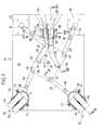
- Fig. 1 ein Fahrwerk als Unteransicht unter die Bodenplatte eines Transportwagens mit gelöster Blockiereinrichtung,
- Fig. 2 eine entsprechende Darstellung, jedoch in arretierter Stellung der Blockiereinrichtung,
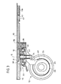
- Fig. 3 einen Schnitt entsprechend der Schnittangabe III-III in Fig. 2,
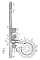
- Fig. 4 einen entsprechenden Schnitt gemäß Schnittlinie IV-IV in Fig. 1,
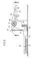
- Fig. 5 einen Schnitt entsprechend der Schnittlinie V-V in Fig. 2,
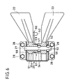
- Fig. 6 einen Schnitt entsprechend der Schnittangabe VI-VI in Fig. 5,
- Fig. 7 einen Schnitt entsprechend der Schnittlinie VII-VII in Fig. 1 und
- Fig. 8 eine Ansicht in Richtung des Ansichtspfeiles VIII in Fig. 1.
- 1 is a chassis as a bottom view under the bottom plate of a trolley with the blocking device released,
- 2 is a corresponding representation, but in the locked position of the blocking device,
- 3 shows a section corresponding to section III-III in FIG. 2,
- 4 shows a corresponding section along section line IV-IV in FIG. 1,
- 5 shows a section along the section line VV in FIG. 2,
- 6 shows a section corresponding to section VI-VI in FIG. 5,
- Fig. 7 is a section along the line VII-VII in Fig. 1 and
- 8 is a view in the direction of the arrow VIII in Fig. 1st
Mit 10 ist eine Bodenplatte eines mit Hilfe eines insgesamt mit 11 bezeichneten Fahrwerks rollbaren Transportbehälters bezeichnet. Das Fahrwerk 11 umfaßt vier, als Schwenkrollen ausgebildete Zwillings-Laufrollen 12, von denen in den Fig. 1 und 2 jeweils ein Paar dargestellt ist. Sie sind jeweils mittels eines Montagebleches 13 und Schrauben 14 auf eine plattenartige Konsole 15 aufgeschraubt, die jeweils ihrerseits an der Bodenplatte 10 befestigt ist.A base plate of a transport container which can be rolled with the aid of a chassis designated as a whole by 11 is designated by 10. The
Etwa in der Mitte der Bodenplatte 10 ist eine plattenartige Schwinge 16 mittels einer Achse 17 in einer bodenparallelen Ebene schwenkbar angeordnet. Jeweils zu verschiedenen Seiten der Achse 17 sind an ihr zwei Lenker-Hebel - nachfolgend kurz als Lenker 18 und 19 bezeichnet - angekuppelt. Jeder Lenker 18, 19 weist einen schlüsselbartartigen Fortsatz 20 auf, der in eine schlüssellochartige Ausnehmung 21 der Schwinge 16 hineinpaßt. Nach dem Einstecken wird jeder Lenker 18, 19 in die in den Fig. 1 und 2 dargestellte bestimmungsgemäße Position geschwenkt, in der er mittels drehriegelartigem Hintergriff an der Schwinge unverlierbar eingehängt ist.Approximately in the middle of the
Der Lenker 18 ist in einer bodenparallelen Ebene verschiebebeweglich mit einem Hebel 22, und analog der Lenker 19 mit einem daneben angeordneten Hebel 23 gekuppelt. Bei dem Hebel 23 handelt es sich um den Feststellhebel, während der Hebel 22 der Lösehebel für die nachfolgend im einzelnen beschriebene Blockiervorrichtung für die Räder 24, 25 der Laufrollen 12 ist. Die beiden Hebel 22 und 23 sind in einer in Aufsicht U-förmigen Hebel-Lagerkonsole 26 auf einer Lagerachse 27 schwenkbeweglich gelagert, die mittels Schrauben 28 an der Bodenplatte 10 angeschraubt ist. Im übrigen sind dies neben den Schrauben 14 und der Lagerschraube 17 für die Schwinge 16 die einzigen des gesamten Fahrwerks.The
Mit der Schwinge 16 sind in radial weiter außenliegender Anordnung als derjenigen der Lenker 18 und 19 eine der Zahl der Laufrollen 12 entsprechende Zahl von Schubstangen 29 angelenkt. Die von der Schwinge 16 wegweisenden freien Enden jeder Schubstange 29 sind schwenkbeweglich in Schwenklagern 30 der Konsolen 15 gelagert. Die Schwenklager 30 sind in den Konsolen 15 als zur Achse 17 hin offene Taschen ausgebildet. Jede Schubstange 29 erstreckt sich von der Schwinge 16 nach außen im wesentlichen in Richtung auf die Schwenkachse S jeder der vier Lenkrollen 12.With the
Ebenfalls im Bereich ihres freien Endes weist jede Schubstange 29 eine Keilfläche 31 auf, die von der Bodenplatte 10 nach unten zur jeweiligen Laufrolle 12 weist und je einen Stößel 32 druckbeaufschlagt, der zentral im Lenkrollenlager 33 vertikal verstellbar aufgenommen ist. Jeder Stößel 32 steht in bewegungsgekuppelter Verbindung über einen Arm 34 mit einem Radbremskörper 35, dessen Außenverzahnung 36 zum Eingriff in eine Gegenverzahnung 37 an einem Rad 25 bestimmt ist. Im Bremseingriffsfall (Fig. 3) ist somit dieses Rad 25 drehblockiert. Die nähere Ausgestaltung dieser Rad- Brems- oder -Blockiereinrichtung ist im übrigen Gegenstand des DE-GM 88 10 731 der Anmelderin, worauf bezüglich konstruktiver Einzelheiten verwiesen wird.Likewise in the region of its free end, each
In der Brems-Lösestellung entsprechend Fig. 1 und Fig. 4 befinden sich die Schubstangen 29 in von den Lenkrollen 12 zurückgezogener Stellung. Zwar kontaktiert jeder Stößel 32 die zugehörige Schubstange 29 druckschlüssig im Bereich ihrer Keilfläche 31 oder eines Aufläufers davon (Fig. 4), doch befindet sich der Stößel 32 in einer oberen Position, die der nicht gebremsten Radstellung entspricht. Wird jetzt durch Betätigung des Feststellhebels 23 - ausgehend von Fig. 1 bzw. 4 - die Schwinge 16 entgegen dem Uhrzeigersinn in Richtung des Pfeiles 38 gedreht, werden alle vier Schubstangen 29 vorgeschoben. Ihre jeweilige Keilfläche 31 schiebt sich auf den Stößel 32 und drückt diesen nach unten in die Bremsstellung entpsrechend Fig. 2 und 3.In the brake release position according to FIGS. 1 and 4, the
An jeder Schubstange 29 ist außerdem ein Hemmschuh 39 angebracht, der aus einem entropieelastischen Werkstoff, insbesondere Gummi oder gummielastischem Kunststoff besteht, und der sich in der Bremsstellung gegen das Rückenlager 40 der zugehörigen Laufrolle 12 preßt, die dadurch daran gehindert ist, um ihre mit der Längsachse des Stößels 32 zusammenfallende Schwenkachse S zu schwenken. In diesem Falle ist die Bremse also einerseits als Drehblockierung für mindestens jeweils ein Rad 25 und gleichzeitig als Schwenkblockierung für jede Lenkrolle 12 ausgelegt.On each
Wie insbesondere aus den Fig. 3 und 4 ersichtlich ist, wird jede aus einem Kunststofformteil bestehende Schubstange 29 unmittelbar auf der Oberfläche der Bodenplatte 10 geführt gehalten und unverlierbar dadurch am Platze gehalten, daß die Schubstange von der Montageplatte 13 der zugehörigen Lenkrolle 12 übergriffen wird. Im übrigen liegt die Schubstange 29 auch stets auf der oberen Stirnfläche des Stößels 32 auf. Die Kupplung jedes den Lenkrollen 12 abgewandten Endes jeder Schubstange 29 mit der Schwinge 16 geschieht einfach dadurch, daß die Schwinge 16 mit einer Kuppelausnehmung 41 einen entsprechenden kreisrunden Kuppelzapfen 42 am Ende der Schubstange 29 übergreift.As can be seen in particular from FIGS. 3 and 4, each
Die beiden Lenker 18 und 19 durchgreifen auf ihrem Weg von der Schwinge 16 zum jeweils zugehörigen Hebel 22 bzw. 23 ein Fenster 43 des zentralen Steges 44 der Hebel-Lagerkonsole 26. An seinem in den Raum der Lagerkonsole 26 eintretenden Ende weist jeder Lenker einen steg- oder rippenartigen Mitnehmer 45 auf, mit dem der Hebel 22 mittels eines Fortsatzes 46 einseitig-zugschlüssig und der Hebel 23 mittels zweier, eine Klaue bildender Fortsätze 47, 48 zug- und druckschlüssig zusammenwirken. In beiden Fällen ist die Anordnung so getroffen, daß jeder Hebel 22, 23 an dem ihm zugeordneten Lenker 18 oder 19 zieht, wenn er niedergetreten wird. Die Trittrichtung für den Hebel 22 ist mit 49 und die für den Hebel 23 mit 50 bezeichnet. Sowohl die beiden Lenker 18 und 19 als auch die beiden Hebel 22 und 23 sind wiederum jeweils einstückige Kunststoffspritzgießteile.The two
Wie Fig. 6 ausweist, sitzt jeder der beiden Nebel 22 und 23 mittels hülsenartiger Achslager 51 bzw. 52 auf der Lagerachse 27. Diese besitzt in axialem Abstand und in jeweils paariger Anordnung Mantelvorsprünge 53 und 54. Diese sind in Form von Rippen durch im wesentlichen tangentiales Stauchen des Werkstoffes der Achse 27 ausgebildet. Die achsaußenseitigen Mantelvorsprünge 53 greifen nach Art von Schlüsselbärten in angepaßte schlüssellochförmige Spalte 55 (Fig. 8) einer der beiden Achslagerwangen 56 der Hebel-Lagerkonsole 26 ein. Das andere Vorsprungspaar 54 sitzt in einer kreisrunden Aufnahme 57, die innerhalb der Lagerhülse 52 des Hebels 23 ausgebildet ist. Folglich wird die Lagerachse 27 durch das formschlüssige Eingreifen der Mantelvorsprünge 53 in die Achslagerwange 56 umdrehbar gehalten, wahrend der Hebel 23 relativ zur festgelegten Achse 27 schwenken kann. Damit Lagerachse und Hebel 23 zusammengesteckt werden können, weist die Lagerbohrung des Nebels 23 in zur Betriebslage umfangsversetzte Anordnung ebenfalls passende "Schlüssellöcher" 63 (Fig. 7) auf.As shown in FIG. 6, each of the two
Die beiden hülsenförmigen Lagerabschnitte 51 und 52 der beiden Hebel 22 und 23 grenzen direkt aneinander an und besitzen eine Gesamtlänge, die im wesentlichen der lichten inneren Weite zwischen den beiden Schenkeln 56 und 58 der Konsole 26 entspricht.The two sleeve-shaped
Auf einem Hülsenabschnitt 51a des Hebels 22 ist eine Schenkel-Rückstellfeder 59 gelagert, deren einer Schenkel 60 unter einem Fortsatz 62 des Nebels 22 druckschlüssig abgestützt ist und deren anderer Schenkel 61 unter Federdruck an der Nebel-Lagerkonsole 26 anliegt (Fig. 5).A
Zur Bedienungsfunktion sei noch folgendes erläutert: wird der Feststellhebel 23 niedergetreten (Pfeil 50) verschwenkt - wie ausgeführt - die Schwinge 16 in Umfangsrichtung 38 und schiebt die Schubstangen 29 in Blockierstellung. Dadurch wird gleichzeitig der Lenker 18 von seinem zugehörigen Nebel 22 in Richtung zur Plattenmitte fortgezogen. Dies hat zur Folge, daß der Lösehebel 22 in die in Fig. 5 gezeichnete Endstellung befördert wird. Soll nun die Feststelleinrichtung wieder gelöst werden, wird dieser Hebel 22 niedergetreten (Pfeil 49), womit vermittels des Fortsatzes 26 der Lenker 18 zum Rand der Bodenplatte 10 gezogen wird. Nach Loslassen springt der Lösehebel nach Fig. 5 zurück in seine günstige Ausgangslage für spätere Betätigung. Der andere Lenker 19 wird zur Plattenmitte hin gezogen. Dies hat zur Folge, daß der Feststellhebel 50 aus seiner der Blockierstellung entsprechenden Lage nach Fig. 7 zurückbefördert wird in die in Fig. 8 dargestellte Lage, in der er durch Tritt in Richtung des Pfeiles 50 erneut betätigbar ist.Regarding the operating function, the following should be explained: the locking
Wichtig ist auch, wie aus Fig. 2 deutlich zu ersehen ist, daß jede Schubstange 29 mit der Schwinge 16 eine Kniehebelanordnung ausbildet, wobei der eine Kniehebel von der Schubstange 29 selbst gebildet wird, der andere Kniehebel von der Verbindung zwischen den Gelenkzapfen 17 und 42 und das Knie mit dem Gelenkzapfen 42 zusammenfällt. Die Blockierstellung nach Fig. 2 zeichnet sich bezüglich der insgesamt vier Kniehebelanordnungen durch deren geringfügige Übertotpunktstellung aus, so daß die Brems- bzw. Blockierstellung automatisch gesichert ist. Ein anderer Vorteil der Kniebelanordnung besteht in der geringen aufzubringenden Betätigungskraft des Feststellhebels 23. Andererseits ist die Kniehebelblockierung durch Niedertreten des Lösehebels 22 unter geringem Kraftaufwand ebenfalls ohne weiteres möglich. Die als elastische Kissen ausgebildeten Nemmschuhe 39 wirken in der Übertotpunktstellung nach Fig. 2 zudem noch toleranzausgleichend und halten die Kniehebelanordnung unter kraftschlüssiger Spannung.It is also important, as can be clearly seen from FIG. 2, that each
Claims (12)
Applications Claiming Priority (2)
| Application Number | Priority Date | Filing Date | Title |
|---|---|---|---|
| DE19904008855 DE4008855A1 (en) | 1990-03-20 | 1990-03-20 | CHASSIS FOR TRANSPORT CONTAINERS, APPARATUS OR THE LIKE |
| DE4008855 | 1990-03-20 |
Publications (1)
| Publication Number | Publication Date |
|---|---|
| EP0447863A1 true EP0447863A1 (en) | 1991-09-25 |
Family
ID=6402599
Family Applications (1)
| Application Number | Title | Priority Date | Filing Date |
|---|---|---|---|
| EP91103168A Withdrawn EP0447863A1 (en) | 1990-03-20 | 1991-03-02 | Undercarriage for containers, appliances etc. |
Country Status (2)
| Country | Link |
|---|---|
| EP (1) | EP0447863A1 (en) |
| DE (1) | DE4008855A1 (en) |
Cited By (4)
| Publication number | Priority date | Publication date | Assignee | Title |
|---|---|---|---|---|
| EP0678438A1 (en) * | 1994-04-21 | 1995-10-25 | Bucher Management AG | Brake system for roll-container |
| NL1006682C2 (en) * | 1997-07-29 | 1999-02-08 | Driessen Aircraft Holding B V | Chassis for a trolley, in particular for a trolley, as well as a trolley provided with such a chassis. |
| DE202016103782U1 (en) | 2016-07-13 | 2016-10-19 | Steinco Paul Vom Stein Gmbh | Device for at least partially simultaneous braking and / or determination of a plurality of arranged on a bottom of a trolley rollers |
| DE102016112884B3 (en) * | 2016-07-13 | 2017-08-24 | Steinco Paul Vom Stein Gmbh | Device for at least partially simultaneous braking and / or determination of a plurality of arranged on a bottom of a trolley rollers |
Families Citing this family (3)
| Publication number | Priority date | Publication date | Assignee | Title |
|---|---|---|---|---|
| DE202005008098U1 (en) * | 2005-05-19 | 2006-09-28 | Wanzl Metallwarenfabrik Gmbh | Dolly |
| DE102012100855A1 (en) * | 2012-02-02 | 2013-08-08 | Sunny Castors Co., Ltd. | Brake roller for use in children chair, hospital bed, wheelchair, storage rack or cupboard, has hinge end formed in control element that is connected with external locking device in hinged manner for moving control element |
| DE102012100853A1 (en) * | 2012-02-02 | 2013-08-08 | Sunny Castors Co., Ltd. | Brake roller for use in e.g. furniture, has locking device connected with joint end of control unit, and brake block whose end forms detent part that engages into detent recesses such that roller part is braked |
Citations (5)
| Publication number | Priority date | Publication date | Assignee | Title |
|---|---|---|---|---|
| GB1338643A (en) * | 1971-02-08 | 1973-11-28 | Tomado Nv | Sub-frame provided with castors |
| FR2200123A1 (en) * | 1972-09-22 | 1974-04-19 | Walle Albert Van De | |
| DE8324703U1 (en) * | 1983-08-27 | 1984-01-12 | Rolf Rodehau GmbH & Co KG Metallwarenfabrik, 6070 Langen | Blocking brake for rollable containers, in particular serving trolleys in commercial aircraft |
| GB2130316A (en) * | 1982-11-17 | 1984-05-31 | Haseltine H L | Goods trolley |
| DE8809849U1 (en) * | 1988-08-02 | 1988-09-22 | Lermer Gmbh, 6200 Wiesbaden, De |
Family Cites Families (3)
| Publication number | Priority date | Publication date | Assignee | Title |
|---|---|---|---|---|
| GB1223039A (en) * | 1968-12-20 | 1971-02-17 | Ici Ltd | Process for the manufacture of methylene bridged polyarylamines |
| DE3431073A1 (en) * | 1983-08-27 | 1985-03-21 | Rolf Rodehau GmbH & Co KG Metallwarenfabrik, 6070 Langen | Locking brake for rolling containers, in particular serving trolleys in commercial aeroplanes |
| DE8810731U1 (en) * | 1988-08-25 | 1988-10-13 | Paul Vom Stein & Co, 5632 Wermelskirchen, De |
-
1990
- 1990-03-20 DE DE19904008855 patent/DE4008855A1/en not_active Withdrawn
-
1991
- 1991-03-02 EP EP91103168A patent/EP0447863A1/en not_active Withdrawn
Patent Citations (5)
| Publication number | Priority date | Publication date | Assignee | Title |
|---|---|---|---|---|
| GB1338643A (en) * | 1971-02-08 | 1973-11-28 | Tomado Nv | Sub-frame provided with castors |
| FR2200123A1 (en) * | 1972-09-22 | 1974-04-19 | Walle Albert Van De | |
| GB2130316A (en) * | 1982-11-17 | 1984-05-31 | Haseltine H L | Goods trolley |
| DE8324703U1 (en) * | 1983-08-27 | 1984-01-12 | Rolf Rodehau GmbH & Co KG Metallwarenfabrik, 6070 Langen | Blocking brake for rollable containers, in particular serving trolleys in commercial aircraft |
| DE8809849U1 (en) * | 1988-08-02 | 1988-09-22 | Lermer Gmbh, 6200 Wiesbaden, De |
Cited By (6)
| Publication number | Priority date | Publication date | Assignee | Title |
|---|---|---|---|---|
| EP0678438A1 (en) * | 1994-04-21 | 1995-10-25 | Bucher Management AG | Brake system for roll-container |
| US5634532A (en) * | 1994-04-21 | 1997-06-03 | Bucher Management Ag | Brake system for traveling container |
| NL1006682C2 (en) * | 1997-07-29 | 1999-02-08 | Driessen Aircraft Holding B V | Chassis for a trolley, in particular for a trolley, as well as a trolley provided with such a chassis. |
| WO1999006260A1 (en) * | 1997-07-29 | 1999-02-11 | Driessen Aircraft Holding B.V. | Underframe for a cart, in particular for a trolley, and a cart provided with such an underframe |
| DE202016103782U1 (en) | 2016-07-13 | 2016-10-19 | Steinco Paul Vom Stein Gmbh | Device for at least partially simultaneous braking and / or determination of a plurality of arranged on a bottom of a trolley rollers |
| DE102016112884B3 (en) * | 2016-07-13 | 2017-08-24 | Steinco Paul Vom Stein Gmbh | Device for at least partially simultaneous braking and / or determination of a plurality of arranged on a bottom of a trolley rollers |
Also Published As
| Publication number | Publication date |
|---|---|
| DE4008855A1 (en) | 1991-09-26 |
Similar Documents
| Publication | Publication Date | Title |
|---|---|---|
| EP0678438B1 (en) | Brake system for roll-container | |
| EP0072491B1 (en) | Brake for rolling containers | |
| EP0447863A1 (en) | Undercarriage for containers, appliances etc. | |
| CH642306A5 (en) | STEERING WHEEL WITH BRAKE DEVICE. | |
| DE19836454C2 (en) | Braked castor for apparatus, devices, furniture or the like | |
| DE2841869A1 (en) | HEEL HOLDER FOR RELEASE SKI BINDING | |
| DE4201012C2 (en) | Drawbar-controlled industrial truck, in particular pallet truck | |
| DE4221541C2 (en) | Braked swivel castor | |
| DE2722230A1 (en) | Brake pedal for castor - with two=step operation block swivel action and brake wheel | |
| DE3019256C2 (en) | ||
| DE202010012390U1 (en) | Braking device for a trolley | |
| DE19827068C1 (en) | Longitudinal adjuster for motor vehicle seat | |
| DE4025157A1 (en) | Hydraulic braking and steering braking device for excavator - uses brake pedal with pivoted pedal plate operating steering braking valve | |
| EP0332876B1 (en) | Cart | |
| DE19525275C2 (en) | Brake device for wheelchairs | |
| DE102021126854A1 (en) | TROLLEY | |
| DE3243211A1 (en) | Castor with a fixing device for blocking the rotational and swivelling movability of the running wheel | |
| DE3245422C2 (en) | ||
| AT331645B (en) | BRAKE DEVICE FOR THE WHEELS OF PACKAGED TRUCK | |
| DE19726311C2 (en) | Suitcase | |
| DE2821157A1 (en) | Brake for swivel castor - has swivel brake independent of wheel brake for manoeuvring in confined spaces | |
| DE202004010097U1 (en) | Manually operated industrial truck or luggage trolley with automatic parking brake has central brake device with by spring element as simple dead-man's-brake; device | |
| DE202021104420U1 (en) | Roller device for mobile containers | |
| DE1605466C3 (en) | Swivel castor with locking lever to block the swiveling and rotating mobility of your wheel | |
| DE2336691A1 (en) | Hand powered transporter brake - operates both as driving and parking brake by pivoting handle against brake shoes |
Legal Events
| Date | Code | Title | Description |
|---|---|---|---|
| PUAI | Public reference made under article 153(3) epc to a published international application that has entered the european phase |
Free format text: ORIGINAL CODE: 0009012 |
|
| AK | Designated contracting states |
Kind code of ref document: A1 Designated state(s): DE FR GB IT NL |
|
| 17P | Request for examination filed |
Effective date: 19920311 |
|
| 17Q | First examination report despatched |
Effective date: 19920716 |
|
| STAA | Information on the status of an ep patent application or granted ep patent |
Free format text: STATUS: THE APPLICATION HAS BEEN WITHDRAWN |
|
| 18W | Application withdrawn |
Withdrawal date: 19930311 |