EP0445408A1 - Process for the reduction of nitrogen oxides contained in waste gases - Google Patents
Process for the reduction of nitrogen oxides contained in waste gases Download PDFInfo
- Publication number
- EP0445408A1 EP0445408A1 EP90124843A EP90124843A EP0445408A1 EP 0445408 A1 EP0445408 A1 EP 0445408A1 EP 90124843 A EP90124843 A EP 90124843A EP 90124843 A EP90124843 A EP 90124843A EP 0445408 A1 EP0445408 A1 EP 0445408A1
- Authority
- EP
- European Patent Office
- Prior art keywords
- reducing agent
- catalyst
- oxides
- nitrogen oxides
- reduction
- Prior art date
- Legal status (The legal status is an assumption and is not a legal conclusion. Google has not performed a legal analysis and makes no representation as to the accuracy of the status listed.)
- Granted
Links
Images
Classifications
-
- B—PERFORMING OPERATIONS; TRANSPORTING
- B01—PHYSICAL OR CHEMICAL PROCESSES OR APPARATUS IN GENERAL
- B01J—CHEMICAL OR PHYSICAL PROCESSES, e.g. CATALYSIS OR COLLOID CHEMISTRY; THEIR RELEVANT APPARATUS
- B01J29/00—Catalysts comprising molecular sieves
- B01J29/04—Catalysts comprising molecular sieves having base-exchange properties, e.g. crystalline zeolites
- B01J29/06—Crystalline aluminosilicate zeolites; Isomorphous compounds thereof
- B01J29/40—Crystalline aluminosilicate zeolites; Isomorphous compounds thereof of the pentasil type, e.g. types ZSM-5, ZSM-8 or ZSM-11, as exemplified by patent documents US3702886, GB1334243 and US3709979, respectively
- B01J29/42—Crystalline aluminosilicate zeolites; Isomorphous compounds thereof of the pentasil type, e.g. types ZSM-5, ZSM-8 or ZSM-11, as exemplified by patent documents US3702886, GB1334243 and US3709979, respectively containing iron group metals, noble metals or copper
- B01J29/46—Iron group metals or copper
-
- B—PERFORMING OPERATIONS; TRANSPORTING
- B01—PHYSICAL OR CHEMICAL PROCESSES OR APPARATUS IN GENERAL
- B01D—SEPARATION
- B01D53/00—Separation of gases or vapours; Recovering vapours of volatile solvents from gases; Chemical or biological purification of waste gases, e.g. engine exhaust gases, smoke, fumes, flue gases, aerosols
- B01D53/34—Chemical or biological purification of waste gases
- B01D53/92—Chemical or biological purification of waste gases of engine exhaust gases
- B01D53/94—Chemical or biological purification of waste gases of engine exhaust gases by catalytic processes
- B01D53/9404—Removing only nitrogen compounds
- B01D53/9409—Nitrogen oxides
- B01D53/9413—Processes characterised by a specific catalyst
- B01D53/9418—Processes characterised by a specific catalyst for removing nitrogen oxides by selective catalytic reduction [SCR] using a reducing agent in a lean exhaust gas
-
- F—MECHANICAL ENGINEERING; LIGHTING; HEATING; WEAPONS; BLASTING
- F01—MACHINES OR ENGINES IN GENERAL; ENGINE PLANTS IN GENERAL; STEAM ENGINES
- F01N—GAS-FLOW SILENCERS OR EXHAUST APPARATUS FOR MACHINES OR ENGINES IN GENERAL; GAS-FLOW SILENCERS OR EXHAUST APPARATUS FOR INTERNAL COMBUSTION ENGINES
- F01N13/00—Exhaust or silencing apparatus characterised by constructional features ; Exhaust or silencing apparatus, or parts thereof, having pertinent characteristics not provided for in, or of interest apart from, groups F01N1/00 - F01N5/00, F01N9/00, F01N11/00
- F01N13/009—Exhaust or silencing apparatus characterised by constructional features ; Exhaust or silencing apparatus, or parts thereof, having pertinent characteristics not provided for in, or of interest apart from, groups F01N1/00 - F01N5/00, F01N9/00, F01N11/00 having two or more separate purifying devices arranged in series
-
- B—PERFORMING OPERATIONS; TRANSPORTING
- B01—PHYSICAL OR CHEMICAL PROCESSES OR APPARATUS IN GENERAL
- B01D—SEPARATION
- B01D2251/00—Reactants
- B01D2251/20—Reductants
- B01D2251/206—Ammonium compounds
- B01D2251/2067—Urea
-
- B—PERFORMING OPERATIONS; TRANSPORTING
- B01—PHYSICAL OR CHEMICAL PROCESSES OR APPARATUS IN GENERAL
- B01D—SEPARATION
- B01D2255/00—Catalysts
- B01D2255/20—Metals or compounds thereof
- B01D2255/207—Transition metals
- B01D2255/20761—Copper
-
- B—PERFORMING OPERATIONS; TRANSPORTING
- B01—PHYSICAL OR CHEMICAL PROCESSES OR APPARATUS IN GENERAL
- B01D—SEPARATION
- B01D2255/00—Catalysts
- B01D2255/50—Zeolites
-
- F—MECHANICAL ENGINEERING; LIGHTING; HEATING; WEAPONS; BLASTING
- F01—MACHINES OR ENGINES IN GENERAL; ENGINE PLANTS IN GENERAL; STEAM ENGINES
- F01N—GAS-FLOW SILENCERS OR EXHAUST APPARATUS FOR MACHINES OR ENGINES IN GENERAL; GAS-FLOW SILENCERS OR EXHAUST APPARATUS FOR INTERNAL COMBUSTION ENGINES
- F01N2370/00—Selection of materials for exhaust purification
- F01N2370/02—Selection of materials for exhaust purification used in catalytic reactors
- F01N2370/04—Zeolitic material
-
- F—MECHANICAL ENGINEERING; LIGHTING; HEATING; WEAPONS; BLASTING
- F01—MACHINES OR ENGINES IN GENERAL; ENGINE PLANTS IN GENERAL; STEAM ENGINES
- F01N—GAS-FLOW SILENCERS OR EXHAUST APPARATUS FOR MACHINES OR ENGINES IN GENERAL; GAS-FLOW SILENCERS OR EXHAUST APPARATUS FOR INTERNAL COMBUSTION ENGINES
- F01N2610/00—Adding substances to exhaust gases
- F01N2610/02—Adding substances to exhaust gases the substance being ammonia or urea
-
- F—MECHANICAL ENGINEERING; LIGHTING; HEATING; WEAPONS; BLASTING
- F01—MACHINES OR ENGINES IN GENERAL; ENGINE PLANTS IN GENERAL; STEAM ENGINES
- F01N—GAS-FLOW SILENCERS OR EXHAUST APPARATUS FOR MACHINES OR ENGINES IN GENERAL; GAS-FLOW SILENCERS OR EXHAUST APPARATUS FOR INTERNAL COMBUSTION ENGINES
- F01N3/00—Exhaust or silencing apparatus having means for purifying, rendering innocuous, or otherwise treating exhaust
- F01N3/08—Exhaust or silencing apparatus having means for purifying, rendering innocuous, or otherwise treating exhaust for rendering innocuous
- F01N3/10—Exhaust or silencing apparatus having means for purifying, rendering innocuous, or otherwise treating exhaust for rendering innocuous by thermal or catalytic conversion of noxious components of exhaust
- F01N3/18—Exhaust or silencing apparatus having means for purifying, rendering innocuous, or otherwise treating exhaust for rendering innocuous by thermal or catalytic conversion of noxious components of exhaust characterised by methods of operation; Control
- F01N3/20—Exhaust or silencing apparatus having means for purifying, rendering innocuous, or otherwise treating exhaust for rendering innocuous by thermal or catalytic conversion of noxious components of exhaust characterised by methods of operation; Control specially adapted for catalytic conversion ; Methods of operation or control of catalytic converters
- F01N3/2066—Selective catalytic reduction [SCR]
- F01N3/208—Control of selective catalytic reduction [SCR], e.g. dosing of reducing agent
-
- F—MECHANICAL ENGINEERING; LIGHTING; HEATING; WEAPONS; BLASTING
- F02—COMBUSTION ENGINES; HOT-GAS OR COMBUSTION-PRODUCT ENGINE PLANTS
- F02B—INTERNAL-COMBUSTION PISTON ENGINES; COMBUSTION ENGINES IN GENERAL
- F02B1/00—Engines characterised by fuel-air mixture compression
- F02B1/02—Engines characterised by fuel-air mixture compression with positive ignition
- F02B1/04—Engines characterised by fuel-air mixture compression with positive ignition with fuel-air mixture admission into cylinder
-
- Y—GENERAL TAGGING OF NEW TECHNOLOGICAL DEVELOPMENTS; GENERAL TAGGING OF CROSS-SECTIONAL TECHNOLOGIES SPANNING OVER SEVERAL SECTIONS OF THE IPC; TECHNICAL SUBJECTS COVERED BY FORMER USPC CROSS-REFERENCE ART COLLECTIONS [XRACs] AND DIGESTS
- Y02—TECHNOLOGIES OR APPLICATIONS FOR MITIGATION OR ADAPTATION AGAINST CLIMATE CHANGE
- Y02T—CLIMATE CHANGE MITIGATION TECHNOLOGIES RELATED TO TRANSPORTATION
- Y02T10/00—Road transport of goods or passengers
- Y02T10/10—Internal combustion engine [ICE] based vehicles
- Y02T10/12—Improving ICE efficiencies
Definitions
- the invention relates to a method for reducing nitrogen oxides contained in exhaust gases, in particular internal combustion engines, by means of a zeolite-containing catalyst.
- the zeolite catalyst which can be configured as a monolithic catalyst or as a bulk catalyst, can preferably contain zeolites of the type X, Y or mordenite.
- the operation of this known method is based on the fact that the nitrogen oxides contained in the exhaust gases, for example of a motor vehicle internal combustion engine, with the hydrocarbons normally also present in the exhaust gases as a reducing agent and those present when a lean fuel-air mixture is burned Oxygen are implemented. This makes it possible to dispense with the known addition of ammonia as a reducing agent, which is problematic for various reasons, particularly in motor vehicles.
- a prerequisite for the described effect of the known method is therefore a certain minimum value of the hydrocarbon concentration in the exhaust gas, since, as described, these serve as reducing agents. Accordingly, the known method is at least not optimally usable in those cases in which, as in the case of diesel engines or gasoline engines with gasoline direct injection, the hydrocarbon concentration in the exhaust gas is significantly lower than the nitrogen oxide concentration.
- this object is achieved by adding urea to the excess-containing exhaust gas stream, avoiding the addition and storage of problematic reducing agents such as ammonia.
- Urea reduces the nitrogen oxides in an exhaust gas stream containing oxygen in excess on a catalyst. This is probably due to the fact that urea (H2N-CO-NH2) easily hydrolyzes to CO2 and 2 NH3 or decomposes to form NH2 radicals.
- urea H2N-CO-NH2
- urea is a storage for a reducing agent.
- Admittedly for example, for the treatment of those emitted by a motor vehicle internal combustion engine Exhaust gases the reducing agent are carried in a vehicle-fixed tank, but it is present in an unproblematic form in the form of an aqueous urea solution, and the reducing agent is only formed later.
- the reducing agent can be metered in such a way that 50% to 200% of the theoretically required amount, preferably 80% to 100% of the required amount, are metered in.
- the addition of reducing agent will accordingly be controlled or regulated as a function of the operating mode or operating parameters of the device producing the exhaust gas, for example an internal combustion engine.
- the operating mode or operating parameters of the device producing the exhaust gas for example an internal combustion engine.
- an internal combustion engine there is a certain nitrogen oxide concentration in the exhaust gas, depending on the respective operating point of the machine, which is defined, for example, by speed and load, and the control or regulation of the addition of reducing agent takes place in such a way that Exhaust gas in the direction of flow behind the zeolitic catalyst contains the smallest possible proportion of reducing agent and nitrogen oxides.
- the Cu-containing zeolitic catalysts claimed in the earlier application only achieve low conversion rates at low exhaust gas temperatures, as is customary in the start-up phase of diesel engines. However, it is desirable to achieve the highest possible conversion during the start-up phase.
- the present invention now relates to a process for the reduction of nitrogen oxides contained in flue gases and exhaust gases, in particular from internal combustion engines, under oxidizing conditions by means of a zeolite catalyst, which may contain exchanged metal ions, and with a reducing agent, which is characterized in that a zeolitic catalyst containing oxides of transition elements from periods 4, 5, 6 and / or oxides of rare earths is used. Groups IIIb to VIII and Ib and IIb are preferred.
- Table 2 shows the increase in the NO conversion rate due to oxidic additives such as. B. TiO2, V2O5, WO3 or CuCr2O4 shown at low temperature.
- Oxidic additives suitable for the process according to the invention are, for example: TiO2, V2O5, Cr2O3, MnO2, Fe2O3, CoO, NiO, CuO, Y2O3, ZrO2, Nb2O5, MoO3, La2O3, Ce2O3, WO3.
- mixtures of the oxides are also suitable.
- the mixtures can contain two or more oxidic components.
- the oxides are used in amounts of 0.1 to 20% by weight, based on the zeolite / binder combination, preferably 0.5 to 10% by weight.
- oxidic additives are TiO2, V2O5, WO3, MoO3, CuCr2O4, La2O3 and Ce2O3.
- the oxidic additives are usually added to the zeolite / binder combination and the mixture is mixed by intensive grinding, e.g. B. homogenized with agitator ball mills. Then the mixtures are granulated by drying and z. B. roller granulators, extruders, pressed to form leagues. A coating of monolithic supports with a suspension of the active components can also be carried out.
- the catalyst described is distinguished by the fact that it is active in a wide temperature range and achieves its activity at low temperature in comparison to non-catalytic processes which operate at 800 ° C. to over 1000 ° C.
- a further increase in the space velocity does not lead to a proportional deterioration in the NO conversion rate, as shown in Table 3 by way of example on a Cu-exchanged zeolite catalyst.
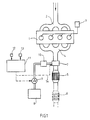
- FIG. 1 shows an exemplary embodiment of a device for carrying out the method according to the invention on a vehicle internal combustion engine.
- the illustrated embodiment is a diesel internal combustion engine 1 with intake pipe 2, fuel supply 3 and exhaust system 4. From this, the exhaust gases reach the zeolitic catalyst 5, which is known in detail from the aforementioned DE-OS 3 642 018 or can have a corresponding composition, and from this into the oxidation catalyst 6, which can also come to an end.
- the zeolitic catalyst 5 which is known in detail from the aforementioned DE-OS 3 642 018 or can have a corresponding composition, and from this into the oxidation catalyst 6, which can also come to an end.
- the zeolite catalyst is designed so that it can also act as an oxidation catalyst.
- Another possibility is to arrange the oxidation catalyst in front of the zeolite catalyst.
- the addition device 7 for a reducing agent containing urea or consisting entirely of urea is stored in liquid form in the tank 8 and is fed to the addition device via a conveyor.
- the conveyor can be a pump or increased pressure in the storage tank (8).
- the heating device 10 has a structure known per se; for example, it can contain a glow plug or an electrically heated hedgehog as essential components. When the machine is warm, the urea is decomposed by the hot exhaust gas.
- the delivery rate is controlled or regulated so that the amount of reducing agent required to reduce the amount of nitrogen oxide present in the exhaust gas is supplied to the exhaust gas at 7.
- the nitrogen oxide content of the exhaust gas depends on the respective operating mode of the internal combustion engine 1, the respective operating point being able to be defined by the respective values of the speed and load of the engine 1.
- the pump is controlled or regulated via a map memory 11 in terms of its delivery rate, to which signals from a speed sensor 12 and a load sensor 13 of the machine 1 are supplied and in which values corresponding to the various speed and load values for the nitrogen oxide content of the exhaust gas of the machine 1 are stored .
- the memory 11 then delivers control signals corresponding to the respective nitrogen oxide content to the pump 9.
- the device 7 which is designed, for example, as an electromagnetic injection valve, can also be controlled accordingly.
- the invention thus creates a possibility for reducing nitrogen oxides contained in exhaust gases while avoiding problematic reducing agents on a zeolite-containing catalyst even with a low hydrocarbon content of the exhaust gases.
Abstract
Description
Die Erfindung betrifft ein Verfahren zur Reduktion von in Abgasen, insbesondere von Verbrennungskraftmaschinen enthaltenen Stickoxiden mittels eines Zeolith-haltigen Katalysators.The invention relates to a method for reducing nitrogen oxides contained in exhaust gases, in particular internal combustion engines, by means of a zeolite-containing catalyst.
Ein derartiges Verfahren sowie eine Einrichtung zur Durchführung desselben sind aus der DE-OS 3 642 018 bekannt. Wie dort im einzelnen ausgeführt, kann der Zeolith-Katalysator, der als monolithischer Katalysator oder als Schüttgut-Katalysator ausgebildet sein kann, bevorzugt Zeolithe vom Typ X, Y oder Mordenit enthalten. Die Wirkungsweise dieses bekannten Verfahrens beruht darauf, daß die in den Abgasen beispielsweise einer Kraftfahrzeug-Brennkraftmaschine enthaltenen Stickoxide mit den ebenfalls in den Abgasen normalerweise vorhandenen Kohlenwasserstoffen als Reduktionsmittel und dem bei Verbrennung eines mageren Kraftstoff-Luft-Gemisches vorhandenen Sauerstoff umgesetzt werden. Damit kann auf die bekannte, aus verschiedenen Gründen insbesondere bei Kraftfahrzeugen problematische Zugabe von Ammoniak als Reduktionsmittel verzichtet werden.Such a method and a device for carrying it out are known from DE-OS 3 642 018. As detailed there, the zeolite catalyst, which can be configured as a monolithic catalyst or as a bulk catalyst, can preferably contain zeolites of the type X, Y or mordenite. The operation of this known method is based on the fact that the nitrogen oxides contained in the exhaust gases, for example of a motor vehicle internal combustion engine, with the hydrocarbons normally also present in the exhaust gases as a reducing agent and those present when a lean fuel-air mixture is burned Oxygen are implemented. This makes it possible to dispense with the known addition of ammonia as a reducing agent, which is problematic for various reasons, particularly in motor vehicles.
Voraussetzung für die beschriebene Wirkung des bekannten Verfahrens ist also ein bestimmter Mindestwert der Kohlenwasserstoff-Konzentration im Abgas, da diese, wie beschrieben, als Reduktionsmittel dienen. Demgemäß ist das bekannte Verfahren in den Fällen zumindest nicht optimal einsetzbar, in denen, wie bei Dieselmaschinen oder Ottomotoren mit Benzin-Direkteinspritzung, die Kohlenwasserstoff-Konzentration im Abgas deutlich geringer als die Stickoxid-Konzentration ist.A prerequisite for the described effect of the known method is therefore a certain minimum value of the hydrocarbon concentration in the exhaust gas, since, as described, these serve as reducing agents. Accordingly, the known method is at least not optimally usable in those cases in which, as in the case of diesel engines or gasoline engines with gasoline direct injection, the hydrocarbon concentration in the exhaust gas is significantly lower than the nitrogen oxide concentration.
In einer prioritätsälteren Anmeldung gemäß P 3 830 045.1 wird diese Aufgabe dadurch gelöst, daß dem Sauerstoff im Überschuß enthaltenden Abgasstrom Harnstoff zugesetzt wird, wobei die Zugabe und Speicherung problematischer Reduktionsmittel wie Ammoniak vermieden wird.In a prior application according to P 3 830 045.1, this object is achieved by adding urea to the excess-containing exhaust gas stream, avoiding the addition and storage of problematic reducing agents such as ammonia.
Harnstoff reduziert dabei die Stickoxide in einem Sauerstoff im Überschuß enthaltenden Abgasstrom an einem Katalysator. Dies beruht wohl darauf, daß Harnstoff (H₂N-CO-NH₂) leicht zu CO₂ und 2 NH₃ hydrolysiert oder sich unter Bildung von NH₂-Radikalen zersetzt.Urea reduces the nitrogen oxides in an exhaust gas stream containing oxygen in excess on a catalyst. This is probably due to the fact that urea (H₂N-CO-NH₂) easily hydrolyzes to CO₂ and 2 NH₃ or decomposes to form NH₂ radicals.
Letztlich ist Harnstoff also ein Speicher für ein reduzierendes Agens. Zwar muß beispielsweise zur Behandlung der von einer Kraftfahrzeug-Brennkraftmaschine emittierten Abgase das Reduktionsmittel in einem fahrzeugfesten Tank mitgeführt werden, jedoch liegt es in unproblematischer Form in Gestalt von wäßriger Harnstofflösung vor, und das reduzierende Agens wird erst später gebildet.Ultimately, urea is a storage for a reducing agent. Admittedly, for example, for the treatment of those emitted by a motor vehicle internal combustion engine Exhaust gases the reducing agent are carried in a vehicle-fixed tank, but it is present in an unproblematic form in the form of an aqueous urea solution, and the reducing agent is only formed later.
Die Zumessung des Reduktionsmittels kann so erfolgen, daß 50 % bis 200 % der theoretisch erforderlichen Menge, bevorzugt 80 % bis 100 % der erforderlichen Menge dosiert werden.The reducing agent can be metered in such a way that 50% to 200% of the theoretically required amount, preferably 80% to 100% of the required amount, are metered in.
An einem Cu-ausgetauschten Zeolith vom ZSM-Typ (ZSM-5) wurde mit Harnstoff beispielsweise folgende NOx-Reduktion erreicht:

Die Reduktionsmittelzugabe wird man demgemäß in Abhängigkeit von der Betriebsweise bzw. Betriebsgrößen der das Abgas erzeugenden Einrichtung, also beispielsweise einer Brennkraftmaschine, steuern oder regeln. Beispielsweise bei einer Fahrzeug-Brennkraftmaschine ergibt sich im Fahrbetrieb in Abhängigkeit von dem jeweiligen Betriebspunkt der Maschine, der zum Beispiel durch Drehzahl und Last definiert ist, im Abgas eine bestimmte Stickoxid-Konzentration, und die Steuerung bzw. Regelung der Reduktionsmittelzugabe erfolgt so, daß das Abgas in Strömungsrichtung hinter dem zeolithischen Katalysator möglichst geringe Anteile an Reduktionsmittel und Stickoxiden enthält.The following NO x reduction, for example, was achieved on a Cu-exchanged zeolite of the ZSM type (ZSM-5):
The addition of reducing agent will accordingly be controlled or regulated as a function of the operating mode or operating parameters of the device producing the exhaust gas, for example an internal combustion engine. For example, in a vehicle internal combustion engine, there is a certain nitrogen oxide concentration in the exhaust gas, depending on the respective operating point of the machine, which is defined, for example, by speed and load, and the control or regulation of the addition of reducing agent takes place in such a way that Exhaust gas in the direction of flow behind the zeolitic catalyst contains the smallest possible proportion of reducing agent and nitrogen oxides.
Im beispielhaften Versuch wird angenommen, daß ein Mol Harnstoff zwei Mol eines reduzierten Agenz bildet. Die Harnstoffdosierung wurde so gewählt, daß ca. 90 % der theoretisch erforderlichen Reduktionsmittelmenge zur Verfügung steht. Die Raumgeschwindigkeit wurde so gewählt, daß 12.900 h⁻¹ erreicht wurden.In the exemplary experiment, it is assumed that one mole of urea forms two moles of a reduced agent. The urea metering was chosen so that about 90% of the amount of reducing agent theoretically required is available. The space velocity was chosen so that 12,900 h⁻¹ were reached.
Die in der älteren Anmeldung beanspruchten Cu-haltigen zeolithischen Katalysatoren erreichen jedoch bei niedrigen Abgastemperaturen, so wie sie in der Anfahrphase bei Dieselkraftmaschinen üblich sind, nur geringe Konvertierungsraten. Wünschenswert ist es aber, bei der Anfahrphase schon eine möglichst hohe Konvertierung zu erzielen.The Cu-containing zeolitic catalysts claimed in the earlier application, however, only achieve low conversion rates at low exhaust gas temperatures, as is customary in the start-up phase of diesel engines. However, it is desirable to achieve the highest possible conversion during the start-up phase.
Daher ist ein wichtiges Kriterium für die Beurteilung eines Katalysators die Anspringtemperatur. Es wurde nun gefunden, daß oxidische Zusätze zum beispielsweise Cuausgetauschten Zeolith-Katalysator die gewünschten Eigenschaften des Katalysators fördern.An important criterion for evaluating a catalyst is therefore the light-off temperature. It has now been found that oxidic additives, for example for the Cu-exchanged zeolite catalyst, promote the desired properties of the catalyst.
Gegenstand der vorliegenden Erfindung ist nun ein Verfahren zur Reduktion von in Rauchgasen und Abgasen, insbesondere von Verbrennungskraftmaschinen, enthaltenen Stickoxiden unter oxydierenden Bedingungen mittels eines Zeolith-Katalysators, der gegebenenfalls ausgetauschte Metallionen enthalten kann, und mit einem Reduktionsmittel, welches dadurch gekennzeichnet ist, daß ein zeolithischer Katalysator, der Oxide der Übergangs-Elemente der Perioden 4, 5, 6 und/oder Oxide der Seltenen Erden enthält, eingesetzt wird. Bevorzugt sind die Gruppen IIIb bis VIII sowie Ib und IIb.The present invention now relates to a process for the reduction of nitrogen oxides contained in flue gases and exhaust gases, in particular from internal combustion engines, under oxidizing conditions by means of a zeolite catalyst, which may contain exchanged metal ions, and with a reducing agent, which is characterized in that a zeolitic catalyst containing oxides of transition elements from periods 4, 5, 6 and / or oxides of rare earths is used. Groups IIIb to VIII and Ib and IIb are preferred.
In Tabelle 2 ist die Erhöhung der NO-Umsatzrate durch oxidische Zusätze wie z. B. TiO₂, V₂O₅, WO₃ oder CuCr₂O₄ bei niedriger Temperatur dargestellt.Table 2 shows the increase in the NO conversion rate due to oxidic additives such as. B. TiO₂, V₂O₅, WO₃ or CuCr₂O₄ shown at low temperature.
Für das erfindungsgemäße Verfahren geeignete oxidische Zusätze sind beispielsweise: TiO₂, V₂O₅, Cr₂O₃, MnO₂, Fe₂O₃, CoO, NiO, CuO, Y₂O₃, ZrO₂, Nb₂O₅, MoO₃, La₂O₃, Ce₂O₃, WO₃.Oxidic additives suitable for the process according to the invention are, for example: TiO₂, V₂O₅, Cr₂O₃, MnO₂, Fe₂O₃, CoO, NiO, CuO, Y₂O₃, ZrO₂, Nb₂O₅, MoO₃, La₂O₃, Ce₂O₃, WO₃.
Ebenfalls geeignet sind entsprechende Mischungen aus den Oxiden. Die Mischungen können zwei oder mehr oxidische Komponenten enthalten.Corresponding mixtures of the oxides are also suitable. The mixtures can contain two or more oxidic components.
Eingesetzt werden die Oxide in Mengen von 0,1 bis 20 Gew % bezogen auf die Zeolith/Bindemittel-Kombination, bevorzugt 0,5 bis 10 Gew %.The oxides are used in amounts of 0.1 to 20% by weight, based on the zeolite / binder combination, preferably 0.5 to 10% by weight.
Besonders geeignete oxidische Zusätze sind TiO₂, V₂O₅, WO₃, MoO₃, CuCr₂O₄, La₂O₃ und Ce₂O₃.Particularly suitable oxidic additives are TiO₂, V₂O₅, WO₃, MoO₃, CuCr₂O₄, La₂O₃ and Ce₂O₃.
Die oxidischen Zusätze werden üblicherweise der Zeolithe/Bindemittel-Kombination zugemischt und die Mischung durch intensive Mahlung, z. B. mit Rührwerkskugelmühlen, homogenisiert. Anschließend werden die Mischungen durch Trocknen granulierfeucht gestellt und mit geeigneten Aggregaten z. B. Walzengranulatoren, Extrudern, zu Formligen verpreßt. Eine Beschichtung von monolithischen Trägern mit einer Suspension aus dem aktiven Komponenten kann ebenfalls vorgenommen werden.

Ein herausragendes Merkmal der gefundenen Katalysatorformulierung ist, daß der Katalysator bei Temperaturen unter 400 °C, schon im Bereich von 200 °C über 70 % NO-Konvertierung erreicht.An outstanding feature of the catalyst formulation found is that the catalyst already achieves over 70% NO conversion at temperatures below 400 ° C, in the range of 200 ° C.
Der beschriebene Katalysator zeichnet sich dadurch aus, daß er in einem breiten Temperaturbereich aktiv ist und seine Aktivität bei niedriger Temperatur im Vergleich zu nicht katalytischen Verfahren erreicht, die bei 800 °C bis über 1000 °C arbeiten.The catalyst described is distinguished by the fact that it is active in a wide temperature range and achieves its activity at low temperature in comparison to non-catalytic processes which operate at 800 ° C. to over 1000 ° C.
Die in Tabelle 2 dargestellten Versuche wurden bei einer Raumgeschwindigkeit von 12.900 h⁻¹ durchgeführt. Dies ist deutlich höher als die bei SCR-Verfahren sonst übliche Raumgeschwindigkeit von ca. 6.000 bis 10.000 h⁻¹.The experiments shown in Table 2 were carried out at a space velocity of 12,900 h⁻¹. This is significantly higher than the space velocity of approx. 6,000 to 10,000 h⁻¹, which is otherwise common with SCR processes.
Eine weitere Erhöhung der Raumgeschwindigkeit führt nicht zu einer proportionalen Verschlechterung der NO-Umsatzrate wie in Tabelle 3 beispielhaft an einem Cuausgetauschten Zeolithkatalysator dargestellt ist.

Die Erfindung wird im folgenden anhand der Fig. 1 erläutert, die ein Ausführungsbeispiel für eine Einrichtung zur Durchführung des erfindungsgemäßen Verfahrens an einer Fahrzeug-Brennkraftmaschine wiedergibt.The invention is explained below with reference to FIG. 1, which shows an exemplary embodiment of a device for carrying out the method according to the invention on a vehicle internal combustion engine.
In dem dargestellten Ausführungsbeispiel handelt es sich um eine Diesel-Brennkraftmaschine 1 mit Ansaugleitung 2, Kraftstoffzuführung 3 und Abgasanlage 4. Von dieser gelangen die Abgase zu dem zeolithischen Katalysator 5, der einen im einzelnen aus der eingangs genannten DE-OS 3 642 018 bekannten Aufbau bzw. eine entsprechende Zusammensetzung besitzen kann, und von diesem in den Oxidationskatalysator 6, der aber auch in Fortfall kommen kann.In the illustrated embodiment, it is a diesel internal combustion engine 1 with
Dies ist dann möglich, wenn der Zeolith-Katalysator so ausgebildet ist, daß er auch als Oxidationskatalysator wirken kann. Eine weitere Möglichkeit ist, den Oxidationskatalysator vor dem Zeolithkatalysator anzuordnen.This is possible if the zeolite catalyst is designed so that it can also act as an oxidation catalyst. Another possibility is to arrange the oxidation catalyst in front of the zeolite catalyst.
In Strömungsrichtung vor dem Zeolithkatalysator 5 liegt die Zugabevorrichtung 7 für ein Harnstoff enthaltendes oder vollständig aus Harnstoff bestehendes Reduktionsmittel. Dieses ist in flüssiger Form in dem Tank 8 gespeichert und wird über eine Fördereinrichtung der Zugabevorrichtung zugeführt. Die Fördereinrichtung kann eine Pumpe sein oder erhöhter Druck im Vorratstank (8).In the flow direction in front of the zeolite catalyst 5 is the addition device 7 for a reducing agent containing urea or consisting entirely of urea. This is stored in liquid form in the tank 8 and is fed to the addition device via a conveyor. The conveyor can be a pump or increased pressure in the storage tank (8).
Die Heizeinrichtung 10 besitzt einen an sich bekannten Aufbau; beispielsweise kann sie als wesentliche Bestandteile eine Glühkerze oder einen elektrisch beheizten Igel enthalten. Bei warmer Maschine erfolgt die Zersetzung des Harnstoffs durch das heiße Abgas.The
Die Fördermenge wird so gesteuert bzw. geregelt, daß die zur Reduktion der jeweils im Abgas vorliegenden Stickoxidmenge erforderliche Menge des Reduktionsmittels bei 7 dem Abgas zugeführt wird. Der Stickoxidgehalt der Abgases ist abhängig von der jeweiligen Betriebsweise der Brennkraftmaschine 1, wobei der jeweilige Betriebspunkt durch die jeweiligen Werte von Drehzahl und Last der Maschine 1 definiert werden kann. Demgemäß wird die Pumpe über einen Kennfeldspeicher 11 hinsichtlich ihrer Fördermenge gesteuert oder geregelt, dem Signale eines Drehzahlsensors 12 und eines Lastsensors 13 der Maschine 1 zugeführt weren und in dem den verschiedenen Drehzahl- und Lastwerten entsprechende Werte für den Stickoxidgehalt des Abgases der Maschine 1 gespeichert sind. Der Speicher 11 liefert dann dem jeweiligen Stickoxidgehalt entspechende Ansteuersignale an die Pumpe 9.The delivery rate is controlled or regulated so that the amount of reducing agent required to reduce the amount of nitrogen oxide present in the exhaust gas is supplied to the exhaust gas at 7. The nitrogen oxide content of the exhaust gas depends on the respective operating mode of the internal combustion engine 1, the respective operating point being able to be defined by the respective values of the speed and load of the engine 1. Accordingly, the pump is controlled or regulated via a
Wie durch die Linie 14 angedeutet, kann statt der Pumpe auch die beispielsweise als elektromagnetisches Einspritzventil ausgebildete Einrichtung 7 entspechend angesteuert werden.As indicated by
Durch die Erfindung ist also eine Möglichkeit zur Reduktion von in Abgasen enthaltenen Stickoxiden unter Vermeidung problematischer Reduktionsmittel an einem zeolithhaltigen Katalysator auch bei geringem Kohlenwasserstoffgehalt der Abgase geschaffen.The invention thus creates a possibility for reducing nitrogen oxides contained in exhaust gases while avoiding problematic reducing agents on a zeolite-containing catalyst even with a low hydrocarbon content of the exhaust gases.
Claims (5)
Applications Claiming Priority (2)
| Application Number | Priority Date | Filing Date | Title |
|---|---|---|---|
| DE4003515A DE4003515A1 (en) | 1990-02-06 | 1990-02-06 | METHOD FOR REDUCING NITROGEN OXIDS CONTAINED IN EXHAUST GAS |
| DE4003515 | 1990-02-06 |
Publications (2)
| Publication Number | Publication Date |
|---|---|
| EP0445408A1 true EP0445408A1 (en) | 1991-09-11 |
| EP0445408B1 EP0445408B1 (en) | 1994-10-12 |
Family
ID=6399550
Family Applications (1)
| Application Number | Title | Priority Date | Filing Date |
|---|---|---|---|
| EP90124843A Expired - Lifetime EP0445408B1 (en) | 1990-02-06 | 1990-12-20 | Process for the reduction of nitrogen oxides contained in waste gases |
Country Status (6)
| Country | Link |
|---|---|
| US (1) | US5085840A (en) |
| EP (1) | EP0445408B1 (en) |
| JP (1) | JP3241053B2 (en) |
| KR (1) | KR0186009B1 (en) |
| DE (2) | DE4003515A1 (en) |
| ES (1) | ES2060917T3 (en) |
Cited By (8)
| Publication number | Priority date | Publication date | Assignee | Title |
|---|---|---|---|---|
| EP0537968A1 (en) * | 1991-10-16 | 1993-04-21 | Toyota Jidosha Kabushiki Kaisha | Nitrogen oxides decreasing apparatus for an internal combustion engine |
| EP0537942A1 (en) * | 1991-10-07 | 1993-04-21 | Ford Motor Company Limited | Method of treating the emissions of a lean-burn engine |
| EP0540196A1 (en) * | 1991-10-07 | 1993-05-05 | Ford Motor Company Limited | Selective reduction of nitrogen oxides |
| DE4200514A1 (en) * | 1992-01-11 | 1993-07-15 | Asea Brown Boveri | Removal of nitrogen@ from turbine exhaust gases - by injection of reduction agent broken into transitional substances by exhaust heat energy before injection to catalytic converter |
| US5612010A (en) * | 1995-01-25 | 1997-03-18 | Gas Metropolitain & Company, Limited | Selective catalytic reduction of nitrogen oxides |
| WO1999029400A1 (en) * | 1997-12-10 | 1999-06-17 | Ab Volvo | Porous material, method and arrangement for catalytic conversion of exhaust gases |
| US6110435A (en) * | 1997-05-13 | 2000-08-29 | Daimlerchrysler Ag | Method and device for nitric oxide reduction in exhaust fumes |
| EP1297885A1 (en) | 2001-09-28 | 2003-04-02 | Volvo Teknisk Utveckling AB | Porous catalyst, method and arrangement for catalytic conversion of exhaust gases |
Families Citing this family (37)
| Publication number | Priority date | Publication date | Assignee | Title |
|---|---|---|---|---|
| US5238890A (en) * | 1990-10-31 | 1993-08-24 | Idemitsu Kosan Company Limited | Exhaust gas purifying catalyst and an exhaust gas purifying method using the catalyst |
| US5208198A (en) * | 1990-12-18 | 1993-05-04 | Tosoh Corporation | Catalyst for purifying exhaust gas |
| DE4203219A1 (en) * | 1992-02-05 | 1993-08-12 | Basf Ag | METHOD FOR REDUCING NITROGEN OXIDE IN EXHAUST GASES BY CONTROLLED NH (ARROW DOWN) 3 (ARROW DOWN) ADDITION |
| DE4206024A1 (en) * | 1992-02-27 | 1993-09-02 | Asea Brown Boveri | METHOD FOR REDUCING STICKOXYDES IN EXHAUST GASES |
| JPH05305240A (en) * | 1992-04-27 | 1993-11-19 | N E Chemcat Corp | Exhaust gas purifying catalyst |
| DE4221451C2 (en) * | 1992-06-30 | 1996-02-29 | Werner Prof Dr Weisweiler | Process and device for catalyzed denitrification of the exhaust gases from diesel engines and lean gasoline engines |
| DE4227741A1 (en) * | 1992-08-21 | 1994-02-24 | Bayerische Motoren Werke Ag | Catalytic denitrification of engine exhaust gas with reducing agent - in amt. controlled according to nitrogen oxide concn. before and/or after redn. and pref. residual reducing agent content |
| US5415850A (en) * | 1993-02-24 | 1995-05-16 | The Research Foundation Of State Univeristy Of New York | Pillared interlayered clay catalysts for the selective reduction of nitrogen oxides with ammonia |
| DE4310926A1 (en) * | 1993-04-02 | 1994-10-06 | Siemens Ag | Device and method for the reduction of pollutant emissions in the exhaust gas |
| DE4310962C1 (en) * | 1993-04-03 | 1994-02-10 | Mtu Friedrichshafen Gmbh | Common exhaust gas unit for several engines - has common exhaust pipe with branch pipes contg. individual SCR catalysts |
| US5354544A (en) * | 1993-12-27 | 1994-10-11 | Ford Motor Company | Selective reduction of nitric oxide |
| DE4425018C1 (en) * | 1994-07-15 | 1995-06-29 | Daimler Benz Ag | Diesel motor exhaust gas cleaner system |
| DE4440833A1 (en) * | 1994-11-15 | 1996-02-08 | Bayerische Motoren Werke Ag | Catalysts and reducing agent injection system preventing emission of nitrogen oxide(s) from lean burning diesel engine |
| US20040086441A1 (en) | 1995-12-06 | 2004-05-06 | Masao Hori | Process for purifying exhaust gas from gasoline engines |
| JP3589763B2 (en) * | 1995-12-06 | 2004-11-17 | 株式会社アイシーティー | Exhaust gas purification method for gasoline engine |
| EP0969915A1 (en) * | 1997-12-12 | 2000-01-12 | FEV Motorentechnik GmbH | Method for reducing nitrogen oxides in exhaust gases containing oxygen, especially exhaust gases from internal combustion engines |
| DE19755600C2 (en) * | 1997-12-15 | 2002-01-17 | Bosch Gmbh Robert | Operation of an internal combustion engine in connection with a NOx storage catalytic converter |
| DE19806265C5 (en) * | 1998-02-16 | 2004-07-22 | Siemens Ag | dosing |
| DE19817994A1 (en) * | 1998-04-22 | 1999-11-04 | Emitec Emissionstechnologie | Method and device for purifying exhaust gas from an internal combustion engine containing nitrogen oxide (NO¶x¶) |
| JP2001303934A (en) | 1998-06-23 | 2001-10-31 | Toyota Motor Corp | Exhaust emission control device for internal combustion engine |
| US6625977B2 (en) | 2000-12-20 | 2003-09-30 | Caterpillar Inc | Method and a system for removing particulates and toxic substances from an exhaust of an engine that use hydrocarbons as a fuel |
| CN1293940C (en) * | 2003-06-10 | 2007-01-10 | 太原理工大学 | Loaded nitrogen oxide purifying catalyst and its preparation |
| US7776265B2 (en) * | 2004-03-18 | 2010-08-17 | Cummins Filtration Ip, Inc. | System for diagnosing reagent solution quality |
| DE102005017402A1 (en) * | 2005-04-15 | 2006-10-19 | Emitec Gesellschaft Für Emissionstechnologie Mbh | Method and device for the metered provision of a, in particular as a solid, reducing agent for exhaust systems |
| DE102005038571A1 (en) * | 2005-08-12 | 2007-02-15 | Emitec Gesellschaft Für Emissionstechnologie Mbh | Method and device for the selective catalytic reduction of nitrogen oxides in the exhaust gas of an internal combustion engine |
| KR100722429B1 (en) * | 2005-09-07 | 2007-05-28 | 계명대학교 산학협력단 | Preparation method of nano size copper-manganese complex oxide catalyst and the catalyst prepared by the method |
| CN101336129A (en) * | 2005-12-14 | 2008-12-31 | 巴斯福催化剂公司 | Zeolite catalyst with improved nox reduction in scr |
| EP2286914B1 (en) * | 2008-05-15 | 2015-08-12 | Mitsui Mining & Smelting Co., Ltd | Method for removing nitrogen oxide by selective catalytic reduction |
| US8545796B2 (en) | 2009-07-31 | 2013-10-01 | Cristal Usa Inc. | Silica-stabilized ultrafine anatase titania, vanadia catalysts, and methods of production thereof |
| RU2670760C9 (en) | 2012-08-17 | 2018-12-17 | Джонсон Мэтти Паблик Лимитед Компани | Zeolite promoted v/ti/w catalysts |
| CA2882336C (en) | 2012-08-24 | 2018-03-06 | Cristal Usa Inc. | Catalyst support materials, catalysts, methods of making them and uses thereof |
| US9067837B2 (en) | 2013-03-15 | 2015-06-30 | Three D Stack, LLC | Cleaning stack gas |
| US9919269B2 (en) | 2013-03-15 | 2018-03-20 | 3D Clean Coal Emissions Stack Llc | Clean coal stack |
| US8821818B1 (en) | 2013-03-15 | 2014-09-02 | Three D Stack, LLC | Cleaning stack gas |
| DE102016207193A1 (en) | 2016-04-27 | 2017-11-02 | Continental Automotive Gmbh | exhaust aftertreatment device |
| CA3024092A1 (en) | 2016-05-14 | 2017-11-23 | 3 D Clean Coal Emissions Stack, Llc | Clean gas stack |
| JP6775037B2 (en) | 2017-02-20 | 2020-10-28 | 株式会社キャタラー | Exhaust gas purification catalyst |
Citations (5)
| Publication number | Priority date | Publication date | Assignee | Title |
|---|---|---|---|---|
| EP0149966A1 (en) * | 1983-11-16 | 1985-07-31 | Mitsubishi Jukogyo Kabushiki Kaisha | Catalyst for treating waste gases |
| DE3642018A1 (en) * | 1985-12-21 | 1987-06-25 | Volkswagen Ag | Process and apparatus for the reduction of nitrogen oxides |
| EP0263399A1 (en) * | 1986-10-08 | 1988-04-13 | Kali-Chemie Aktiengesellschaft | Process for the catalytic reduction of nitrogen oxides |
| DE3830045A1 (en) * | 1988-09-03 | 1990-03-15 | Bayer Ag | METHOD FOR REDUCING NITROGEN OXIDES CONTAINED IN EXHAUST GASES BY MEANS OF A CATALYST CONTAINING ZEOLITE |
| DE3841990A1 (en) * | 1988-12-14 | 1990-06-21 | Degussa | PROCESS FOR REDUCING STICK OXIDES FROM EXHAUST GASES |
Family Cites Families (2)
| Publication number | Priority date | Publication date | Assignee | Title |
|---|---|---|---|---|
| JPS5169476A (en) * | 1974-12-13 | 1976-06-16 | Toray Industries | |
| SU1433486A1 (en) * | 1986-07-07 | 1988-10-30 | Московский химико-технологический институт им.Д.И.Менделеева | Method of cleaning gases from nitrogen oxides |
-
1990
- 1990-02-06 DE DE4003515A patent/DE4003515A1/en not_active Withdrawn
- 1990-12-20 ES ES90124843T patent/ES2060917T3/en not_active Expired - Lifetime
- 1990-12-20 EP EP90124843A patent/EP0445408B1/en not_active Expired - Lifetime
- 1990-12-20 DE DE59007453T patent/DE59007453D1/en not_active Expired - Fee Related
-
1991
- 1991-01-28 US US07/646,815 patent/US5085840A/en not_active Expired - Lifetime
- 1991-02-01 JP JP03138091A patent/JP3241053B2/en not_active Expired - Fee Related
- 1991-02-06 KR KR1019910001995A patent/KR0186009B1/en not_active IP Right Cessation
Patent Citations (5)
| Publication number | Priority date | Publication date | Assignee | Title |
|---|---|---|---|---|
| EP0149966A1 (en) * | 1983-11-16 | 1985-07-31 | Mitsubishi Jukogyo Kabushiki Kaisha | Catalyst for treating waste gases |
| DE3642018A1 (en) * | 1985-12-21 | 1987-06-25 | Volkswagen Ag | Process and apparatus for the reduction of nitrogen oxides |
| EP0263399A1 (en) * | 1986-10-08 | 1988-04-13 | Kali-Chemie Aktiengesellschaft | Process for the catalytic reduction of nitrogen oxides |
| DE3830045A1 (en) * | 1988-09-03 | 1990-03-15 | Bayer Ag | METHOD FOR REDUCING NITROGEN OXIDES CONTAINED IN EXHAUST GASES BY MEANS OF A CATALYST CONTAINING ZEOLITE |
| DE3841990A1 (en) * | 1988-12-14 | 1990-06-21 | Degussa | PROCESS FOR REDUCING STICK OXIDES FROM EXHAUST GASES |
Cited By (11)
| Publication number | Priority date | Publication date | Assignee | Title |
|---|---|---|---|---|
| EP0537942A1 (en) * | 1991-10-07 | 1993-04-21 | Ford Motor Company Limited | Method of treating the emissions of a lean-burn engine |
| EP0540196A1 (en) * | 1991-10-07 | 1993-05-05 | Ford Motor Company Limited | Selective reduction of nitrogen oxides |
| EP0537968A1 (en) * | 1991-10-16 | 1993-04-21 | Toyota Jidosha Kabushiki Kaisha | Nitrogen oxides decreasing apparatus for an internal combustion engine |
| US5412946A (en) * | 1991-10-16 | 1995-05-09 | Toyota Jidosha Kabushiki Kaisha | NOx decreasing apparatus for an internal combustion engine |
| DE4200514A1 (en) * | 1992-01-11 | 1993-07-15 | Asea Brown Boveri | Removal of nitrogen@ from turbine exhaust gases - by injection of reduction agent broken into transitional substances by exhaust heat energy before injection to catalytic converter |
| US5612010A (en) * | 1995-01-25 | 1997-03-18 | Gas Metropolitain & Company, Limited | Selective catalytic reduction of nitrogen oxides |
| US6110435A (en) * | 1997-05-13 | 2000-08-29 | Daimlerchrysler Ag | Method and device for nitric oxide reduction in exhaust fumes |
| DE19719998C2 (en) * | 1997-05-13 | 2003-10-30 | Daimler Chrysler Ag | Method and device for nitrogen oxide reduction in the exhaust gas of a combustion device |
| WO1999029400A1 (en) * | 1997-12-10 | 1999-06-17 | Ab Volvo | Porous material, method and arrangement for catalytic conversion of exhaust gases |
| US7033969B1 (en) | 1997-12-10 | 2006-04-25 | Volvo Car Corporation | Porous material, method and arrangement for catalytic conversion of exhaust gases |
| EP1297885A1 (en) | 2001-09-28 | 2003-04-02 | Volvo Teknisk Utveckling AB | Porous catalyst, method and arrangement for catalytic conversion of exhaust gases |
Also Published As
| Publication number | Publication date |
|---|---|
| US5085840A (en) | 1992-02-04 |
| KR0186009B1 (en) | 1999-10-01 |
| ES2060917T3 (en) | 1994-12-01 |
| DE4003515A1 (en) | 1991-08-08 |
| EP0445408B1 (en) | 1994-10-12 |
| DE59007453D1 (en) | 1994-11-17 |
| JPH04215821A (en) | 1992-08-06 |
| KR910015333A (en) | 1991-09-30 |
| JP3241053B2 (en) | 2001-12-25 |
Similar Documents
| Publication | Publication Date | Title |
|---|---|---|
| EP0445408B1 (en) | Process for the reduction of nitrogen oxides contained in waste gases | |
| EP0364694B2 (en) | Process for reducing nitrogen oxides in waste gases with a zeolite containing catalyst | |
| DE102011110164B4 (en) | Exhaust aftertreatment system with bifunctional catalyst materials and method for lean exhaust NOx reduction | |
| EP2428659B1 (en) | Catalytic convertor for removing nitrogen oxides from the exhaust gas of diesel motors | |
| EP0988104B1 (en) | Method and device for eliminating oxide pollutants in an exhaust gas containing oxygen and engine operating thereby | |
| EP0800856B1 (en) | Catalyst for treating exhaust gases from diesel engines | |
| DE19719998C2 (en) | Method and device for nitrogen oxide reduction in the exhaust gas of a combustion device | |
| DE102018111635A1 (en) | ELECTRIC HEATERS COMPRISING CORROSION RESISTANT METALS AND SELECTIVE CATALYTIC REDUCTION DEVICES USING THE SAME | |
| EP0286967A2 (en) | Process and device for reducing nitrogen oxides | |
| DE102012222806A1 (en) | An exhaust system for a lean-burn internal combustion engine comprising a PGM component and an SCR catalyst | |
| EP1137486A2 (en) | Catalyst body and method for the degradation of nitrogen oxides | |
| DE19546484A1 (en) | Process for operating a cleaning system for gases and a cleaning system for gases | |
| DE102010039975A1 (en) | Multifunctional catalyst block and method of use | |
| DE102011012799A1 (en) | Catalyst useful for removing nitrogen oxide from an exhaust gas of diesel engine comprises a carrier body of length (L) and a catalytically active coating made of at least one material zone | |
| DE102013205197A1 (en) | Carbon Monoxide Selective Oxidation Catalysts | |
| DE3642018A1 (en) | Process and apparatus for the reduction of nitrogen oxides | |
| EP1543225B1 (en) | Exhaust gas purification system of an internal combustion engine and method for purifying the exhaust gases thereof | |
| EP3695902B1 (en) | Catalyst for reducing nitrogen oxides | |
| DE102018113212A1 (en) | Exhaust systems using pilot turbine reducer injections and methods of controlling same | |
| DE102017121998A1 (en) | OXIDATION CATALYST FOR DIESEL ENGINE EXHAUST | |
| DE4338883B4 (en) | Catalyst arrangement for reducing nitrogen oxides contained in oxygen-containing exhaust gases | |
| DE102016121509B4 (en) | Device and method for exhaust gas aftertreatment of an internal combustion engine | |
| WO2003016688A1 (en) | Catalyst system, use thereof and method for operating the same | |
| DE10065473A1 (en) | Process and converter for the catalytic conversion of fuel | |
| DE102019129452A1 (en) | Process for the aftertreatment of the exhaust gas of an internal combustion engine |
Legal Events
| Date | Code | Title | Description |
|---|---|---|---|
| PUAI | Public reference made under article 153(3) epc to a published international application that has entered the european phase |
Free format text: ORIGINAL CODE: 0009012 |
|
| 17P | Request for examination filed |
Effective date: 19901220 |
|
| AK | Designated contracting states |
Kind code of ref document: A1 Designated state(s): BE DE ES FR GB IT |
|
| 17Q | First examination report despatched |
Effective date: 19930210 |
|
| GRAA | (expected) grant |
Free format text: ORIGINAL CODE: 0009210 |
|
| AK | Designated contracting states |
Kind code of ref document: B1 Designated state(s): BE DE ES FR GB IT |
|
| REF | Corresponds to: |
Ref document number: 59007453 Country of ref document: DE Date of ref document: 19941117 |
|
| REG | Reference to a national code |
Ref country code: ES Ref legal event code: FG2A Ref document number: 2060917 Country of ref document: ES Kind code of ref document: T3 |
|
| ITF | It: translation for a ep patent filed |
Owner name: ING. C. GREGORJ S.P.A. |
|
| ET | Fr: translation filed | ||
| GBT | Gb: translation of ep patent filed (gb section 77(6)(a)/1977) |
Effective date: 19950117 |
|
| PLBE | No opposition filed within time limit |
Free format text: ORIGINAL CODE: 0009261 |
|
| STAA | Information on the status of an ep patent application or granted ep patent |
Free format text: STATUS: NO OPPOSITION FILED WITHIN TIME LIMIT |
|
| 26N | No opposition filed | ||
| REG | Reference to a national code |
Ref country code: GB Ref legal event code: IF02 |
|
| PGFP | Annual fee paid to national office [announced via postgrant information from national office to epo] |
Ref country code: DE Payment date: 20031121 Year of fee payment: 14 |
|
| PGFP | Annual fee paid to national office [announced via postgrant information from national office to epo] |
Ref country code: FR Payment date: 20031215 Year of fee payment: 14 |
|
| PGFP | Annual fee paid to national office [announced via postgrant information from national office to epo] |
Ref country code: GB Payment date: 20031217 Year of fee payment: 14 Ref country code: ES Payment date: 20031217 Year of fee payment: 14 |
|
| PGFP | Annual fee paid to national office [announced via postgrant information from national office to epo] |
Ref country code: BE Payment date: 20031231 Year of fee payment: 14 |
|
| PG25 | Lapsed in a contracting state [announced via postgrant information from national office to epo] |
Ref country code: GB Free format text: LAPSE BECAUSE OF NON-PAYMENT OF DUE FEES Effective date: 20041220 |
|
| PG25 | Lapsed in a contracting state [announced via postgrant information from national office to epo] |
Ref country code: ES Free format text: LAPSE BECAUSE OF NON-PAYMENT OF DUE FEES Effective date: 20041221 |
|
| PG25 | Lapsed in a contracting state [announced via postgrant information from national office to epo] |
Ref country code: BE Free format text: LAPSE BECAUSE OF NON-PAYMENT OF DUE FEES Effective date: 20041231 |
|
| BERE | Be: lapsed |
Owner name: *VOLKSWAGEN A.G. Effective date: 20041231 Owner name: *BAYER A.G. Effective date: 20041231 |
|
| PG25 | Lapsed in a contracting state [announced via postgrant information from national office to epo] |
Ref country code: DE Free format text: LAPSE BECAUSE OF NON-PAYMENT OF DUE FEES Effective date: 20050701 |
|
| GBPC | Gb: european patent ceased through non-payment of renewal fee |
Effective date: 20041220 |
|
| PG25 | Lapsed in a contracting state [announced via postgrant information from national office to epo] |
Ref country code: FR Free format text: LAPSE BECAUSE OF NON-PAYMENT OF DUE FEES Effective date: 20050831 |
|
| REG | Reference to a national code |
Ref country code: FR Ref legal event code: ST |
|
| PG25 | Lapsed in a contracting state [announced via postgrant information from national office to epo] |
Ref country code: IT Free format text: LAPSE BECAUSE OF NON-PAYMENT OF DUE FEES;WARNING: LAPSES OF ITALIAN PATENTS WITH EFFECTIVE DATE BEFORE 2007 MAY HAVE OCCURRED AT ANY TIME BEFORE 2007. THE CORRECT EFFECTIVE DATE MAY BE DIFFERENT FROM THE ONE RECORDED. Effective date: 20051220 |
|
| REG | Reference to a national code |
Ref country code: ES Ref legal event code: FD2A Effective date: 20041221 |
|
| BERE | Be: lapsed |
Owner name: *VOLKSWAGEN A.G. Effective date: 20041231 Owner name: *BAYER A.G. Effective date: 20041231 |