EP0444997B1 - Circuit for controlling the power supply of a plurality of electronic modules - Google Patents
Circuit for controlling the power supply of a plurality of electronic modules Download PDFInfo
- Publication number
- EP0444997B1 EP0444997B1 EP91400432A EP91400432A EP0444997B1 EP 0444997 B1 EP0444997 B1 EP 0444997B1 EP 91400432 A EP91400432 A EP 91400432A EP 91400432 A EP91400432 A EP 91400432A EP 0444997 B1 EP0444997 B1 EP 0444997B1
- Authority
- EP
- European Patent Office
- Prior art keywords
- circuit
- modules
- line
- supply
- data bus
- Prior art date
- Legal status (The legal status is an assumption and is not a legal conclusion. Google has not performed a legal analysis and makes no representation as to the accuracy of the status listed.)
- Expired - Lifetime
Links
Images

Classifications
-
- H—ELECTRICITY
- H02—GENERATION; CONVERSION OR DISTRIBUTION OF ELECTRIC POWER
- H02J—CIRCUIT ARRANGEMENTS OR SYSTEMS FOR SUPPLYING OR DISTRIBUTING ELECTRIC POWER; SYSTEMS FOR STORING ELECTRIC ENERGY
- H02J1/00—Circuit arrangements for dc mains or dc distribution networks
- H02J1/14—Balancing the load in a network
-
- B—PERFORMING OPERATIONS; TRANSPORTING
- B60—VEHICLES IN GENERAL
- B60R—VEHICLES, VEHICLE FITTINGS, OR VEHICLE PARTS, NOT OTHERWISE PROVIDED FOR
- B60R16/00—Electric or fluid circuits specially adapted for vehicles and not otherwise provided for; Arrangement of elements of electric or fluid circuits specially adapted for vehicles and not otherwise provided for
- B60R16/02—Electric or fluid circuits specially adapted for vehicles and not otherwise provided for; Arrangement of elements of electric or fluid circuits specially adapted for vehicles and not otherwise provided for electric constitutive elements
- B60R16/03—Electric or fluid circuits specially adapted for vehicles and not otherwise provided for; Arrangement of elements of electric or fluid circuits specially adapted for vehicles and not otherwise provided for electric constitutive elements for supply of electrical power to vehicle subsystems or for
- B60R16/0315—Electric or fluid circuits specially adapted for vehicles and not otherwise provided for; Arrangement of elements of electric or fluid circuits specially adapted for vehicles and not otherwise provided for electric constitutive elements for supply of electrical power to vehicle subsystems or for using multiplexing techniques
-
- H—ELECTRICITY
- H02—GENERATION; CONVERSION OR DISTRIBUTION OF ELECTRIC POWER
- H02J—CIRCUIT ARRANGEMENTS OR SYSTEMS FOR SUPPLYING OR DISTRIBUTING ELECTRIC POWER; SYSTEMS FOR STORING ELECTRIC ENERGY
- H02J2310/00—The network for supplying or distributing electric power characterised by its spatial reach or by the load
- H02J2310/40—The network being an on-board power network, i.e. within a vehicle
- H02J2310/46—The network being an on-board power network, i.e. within a vehicle for ICE-powered road vehicles
Definitions
- the present invention relates to a device for controlling the electrical supply of a plurality of electronic modules and, more particularly, to such a device making it possible to selectively control this supply depending on whether the device is in standby state or when active state.
- Today's motor vehicles are increasingly loaded with electronic modules associated with sensors and actuators to provide control functions for organs such as headlights, wipers, displays of on-board computers, etc. fuel injection control in an internal combustion engine propelling the vehicle, adaptive suspension control or anti-lock of the vehicle wheels. It is now envisaged to electrically supply these modules with a common supply line or bus and to interconnect the modules with a local multiplexed communications system comprising a data bus common to all the modules.
- Publication EP-A-0 327 456 proposes the operational state and a standby state of the electronic boxes by means of messages circulating in a communication channel to which these boxes are connected. For this, it is necessary to stop supplying the modules via the supply bus by isolating the latter from the battery. When the system is thus put in the "standby" state, it is however necessary that the request for certain functions is capable of "waking up” the entire system. This is the case, for example, when the driver actuates an ignition key to start the vehicle. It is then necessary that certain parts of the modules remain supplied in standby state, to allow the system to "wake up”.
- the threshold is then a function of the number of modules or stations which are likely to wake up the system. This threshold must then be adjusted according to the "options" present in the vehicle, options which are known to be chosen arbitrarily by the vehicle owner from a list of options made available by the manufacturer.
- the detection of a current threshold being exceeded does not make it possible to identify the module which is at the origin of the system awakening. Such an identification would however be advantageous in that it would make it possible to seek in priority the function which is at the origin of the alarm clock.
- the present invention therefore aims to provide a device for controlling the electrical supply of a plurality of electronic modules, which does not have these drawbacks of the devices of the prior art.
- the object of the present invention is to produce such a device equipped with means for awakening the entire device which do not require adjustments as a function of the consumption of the modules capable of waking up the device.
- the present invention also aims to produce such a device which is well immune to noise due to electrical and electromagnetic disturbances present in the environment of a motor vehicle.
- Another object of the present invention is to produce such a device which comprises means for identifying the module which is responsible for waking the device.
- data processing center of the type which includes a common power supply line for the modules
- this device being remarkable in that it comprises means installed in the central unit and sensitive to a predetermined state of the device for controlling its setting in the standby state by cutting off the supply of the modules via the common line and then ensuring the electrical supply of at least one circuit for generating wake-up signals forming part of a module, by means of at least a line of the data bus, and means sensitive to the wake-up signals emitted by the circuit for generating such signals, to cut off the supply of the modules by the donation bus and to restore the power supply to the modules via the common power supply line.
- At least one of the modules comprises means for selectively triggering a circuit for generating associated wake-up signals, a coupling circuit associated with this generation circuit for transmitting these signals over the data bus and a detection circuit. interposed between the bus and the central unit and sensitive to these signals to transmit to the central unit control information for waking up the device.
- the device further comprises a voltage regulator put into service by the central unit when the supply of the modules is cut off by the common supply line, to supply the detection circuit and, through the data bus, the circuit coupling and the wake-up signal generation circuit of each module equipped with such circuits.
- the wake-up signal generation circuit generates a pulse sequence, the coupling circuit comprising means for modulating, under the control of this sequence, the current flowing in the line of the data bus used for supplying a part of the module in standby period, the detection circuit being sensitive to this modulated current for transmitting wake-up information to the central unit.
- the modulation means is a transistor whose emitter-collector circuit is connected between ground and the line of the data bus which serves as a supply line in standby period, the circuit for generating wake-up signals controlling the base of this transistor to modulate the current in this line.
- the pulse sequence emitted by a module is specific to it and the central unit comprises means for identifying the module emitting the sequence, from the signal transmitted by the detection circuit.
- the control device comprises several electronic modules M1, M2, etc ... powered by a source of continuous electrical energy 1 via two common lines 2, 3 respectively connected to the positive and negative terminals of the source 1.
- the source of electrical energy is constituted by the vehicle battery.
- Lines 2, 3 thus constitute a "supply bus" to which voltage regulators 4, 4 ′, etc. are connected, each forming part of one of the modules M1, M2, respectively, to supply it with power. after awakening of said module, as will be seen in the remainder of this description.
- the modules each provide a specific application.
- an electronic module can be associated with a block of joysticks placed in a motor vehicle near the steering wheel, to allow the driver to control the issuance of activation / deactivation orders of various components of the vehicle.
- Another module can also be associated with an optical unit of the vehicle to process orders of switching on / off of headlights, position lights, etc. All the modules are interconnected with each other and with a central data processing unit 5, as is the case in particular in a "bodywork” or "class A" multiplex network where this unit centralizes the intelligence necessary for the execution of the various functions for controlling headlights, lights, windshield wipers, displaying data on an on-board computer, etc.
- a module M1, M2 includes a protocol controller 6,6 ′ interposed between a data bus 7 common to all the modules and to the central unit 5, and means 8, 8 ′ respectively, each constituting an application circuit specific to the functions performed (switching on or off a bulb, counting pulses to determine the distance traveled and the speed of the vehicle, etc.).
- the data bus is a two-line bus (DATA, DATA ) powered by differential digital signals, in particular for reasons of noise immunity.
- VLSI very high integration wired logic
- modules can be equipped with means designed to trigger the awakening of the entire device, while other modules are not equipped with such means.
- a module associated with the lever block of a motor vehicle must be equipped with such wake-up means because it is in this block that the driver introduces an ignition key to control the starting of the engine. The rotation of this key must cause the device to wake up from a standby state previously established to minimize the power consumption of the vehicle, for example during a standstill thereof.
- Other modules must also be able to wake up the device, for example a module associated with a vehicle defense system against intrusions.
- the invention is particularly interested in the organization of modules such as modules M1 or M2.
- the protocol controller is interconnected to the data bus 7 through a line transceiver 9, 9 ′, possibly associated with filter 10, 10 ′, an isolation circuit 11, 11 ′ from the transmitter -Receiver being further provided for a purpose which will be explained later.
- the latter circuit is itself supplied by the voltage regulator 4, 4 ′, just like the protocol controller 6, 6 ′.
- the modules M1 and M2 further each comprise a circuit for generating wake-up signals 12, 12 ′, respectively, activated by a trigger means such as a switch 13, 13 ′.
- a trigger means such as a switch 13, 13 ′.
- Such a switch can be closed by the introduction of an ignition key into the lock of a lever block of a motor vehicle, as seen above. The introduction of such a key being significant of a starting action of the vehicle, it is then necessary to "wake up" the electronic modules which control various actuators incorporated in this vehicle. According to the invention, this awakening is caused by the emission of a sequence of signals generated by the generation circuit 12 and transmitted to the central unit 5 via a coupling circuit 14 (or 14 ′ in module M2), a detection circuit 15 and a possible filtering circuit 16.
- the electrical consumption of all the modules is reduced during the standby period, by cutting off the supply of these modules by the supply bus 2, 3 and then only supplying the circuits required to wake up the assembly, via the data bus.
- This power supply then replaces that established during a period of complete activity of the modules, by connection lines 22, 22 ′ to line 2 of the power bus.
- the power supply in standby time of the only circuits necessary for the transmission and processing of the wake-up signals makes it possible to considerably reduce the electrical consumption of the modules compared to that which is observed when all the electronic modules are active, (commonly, 2 to 25 amps).
- the central unit 5 thus prevented, opens a disconnector 17 which cuts the connection of the line 2 to the battery 1 and closes a switch 18 to ensure the connection to the battery of a voltage regulator 19 which supplies the line DATA of the data bus, the detection circuit 15 and the filtering circuit 16.
- the circuits 12, 12 ′ and 14, 14 ′ of the modules M1 and M2 respectively are then supplied by the line DATA while the voltage regulators 4, 4 ′ cease to be supplied by the battery, the line 2 being cut. It follows that the protocol controllers 6, 6 ′ and the application circuits 8, 8 ′ normally supplied by the regulators 4, 4 ′ stop being supplied, which greatly reduces the current required from the battery.
- the isolation circuits 11, 11 ′ are normally supplied by the regulators 4, 4 ′ respectively, to ensure the transmission of information coming from the data bus 7 to the protocol controllers 6, 6 ′ respectively.
- the power supply to these circuits is cut off, to prevent the current coming, in standby state, from the DATA line from coming to supply the protocol controllers 6, 6 ′ through line transceivers 9, 9 ′.
- the power supply of the device being thus adjusted for a standby state, only the circuits 12, 12 ′, 14, 14 ′, 15 and 16 remain active.
- the circuit 12 supplied with electrical energy by an ALIM line via the coupling circuit 14, supplies the latter a sequence of "wake-up" signals.
- the coupling circuit 14, which will be described later in detail in connection with FIG. 2, then modulates the supply current which it receives from the line DATA by the control line 15, according to the sequence of signals received from the circuit 12, so as to establish on the line DATA current signals suitable for being read by the detection circuit 15 and filtered by the circuit 16, before being transmitted to the central unit 5 by a line 20.
- the purpose of the filtering is to eliminate parasitic pulses of duration not calibrated, induced by possible electromagnetic interference from the data bus.
- the sequence of signals emitted by the circuit 12 is particular to the module from which it originates and the central unit can then identify this module by recognizing the particular sequence attached to it. This identification gives the central unit the possibility of modulating the awakening of the device as a function of the origin of the awakening action, as we saw above in the preamble to this description.
- a software for "awakening detection” installed in the central unit 5 decodes the sequence of signals received from line 20 and in return commands the closing of the disconnector 17 and the opening of the switch 18, to restore the power supply to the modules via the power bus, as appropriate in normal operation of these modules.
- the central unit includes other software designed to analyze the multiplexed signals received by the data bus 7, to deduce a possible transition to the inactive state of the vehicle and then switch the power supply to this device in the "standby" configuration.
- this software can be sensitive for example, to the absence, for a predetermined time, of signals normally received from certain sensors or actuators, significant absence of inactivity of the vehicle.
- the withdrawal of the ignition key is a significant action of a transition to the inactive state of the vehicle which can be detected and interpreted in this sense by the software for "detection of transition to mode standby".
- this bus in current rather than in voltage because, in the medium highly disturbed from the electromagnetic point of view that constitutes a motor vehicle, it thus overcomes number of parasitic voltage signals induced electromagnetically in the bus by the environment.
- the information circulating on the data bus in the form of current pulses, the role of the line transceivers is to ensure a current / voltage conversion of these pulses to make them intelligible to the protocol controllers and a voltage / current conversion from a controller to the bus.
- FIG. 2 of the appended drawing in which a diagram of a coupling circuit such as circuit 14 of the module M1 has been shown.
- This circuit is connected by a line 22 to line 2 of the power bus connected to the positive pole of the battery 1.
- the circuit is also connected to the line DATA from the data bus 7 via line 21 and supplies the generation circuit 12 with wake-up signals via the line ALIM, this circuit 12 delivering corresponding pulses IMP to the coupling circuit, to modulate the current in the line DATA as will be explained later.
- the generation circuit 12 requires a reset synchronous RESET with the passage of the device in standby state.
- line 22 goes to a low voltage level and this level is transmitted to the reset input of the circuit 12 by a line 23, through a filtering circuit (C1, R2) capable of absorbing the voltage pulse which appears when the vehicle engine is started.
- Load resistors R1 and R7 are introduced between line 22 and line 23 on the one hand, between the filter inlet (C1, R2) and ground on the other hand.
- Line 22 is connected to the supply line ALIM of circuit 12 via a diode D1.
- a Zener diode Z1 of 10 volts breakdown voltage for example, protects circuit 12 from overvoltages on line 22. Realized in current CMOS technology, circuit 12 can withstand voltages up to 18 volts. It is therefore well protected by the Zener diode Z1.
- a capacitor C2 is placed in parallel on the diode Z1, between the input ALIM of the circuit 12 and the ground. Capacity C2 filters out transient disturbances in the supply.
- the power to circuit 12 is provided by the line DATA connected to the ALIM input of the circuit via a diode D2 and a resistor R6 forming part of a filtering circuit (C2, R6).
- This supply voltage is +5 volts for example.
- the diode Z1 is then blocked and does not consume.
- Diode D1 is also blocked and prevents the passage of current from the line DATA to line 22.
- the diode D1 prevents the supply voltage of circuit 12 from following the voltage of the battery when it drops suddenly (when starting the vehicle for example) and then ensures the diode D2 blocked.
- the actual coupling section of circuit 14 is constituted by a transistor T1, of the NPN type for example, whose collector-emitter circuit is connected between the line DATA and mass.
- a load resistor R3 is placed on the collector of transistor T1.
- the base of transistor T1 is connected to the midpoint of a voltage divider made up of resistors (R4, R5), a capacitance C3 transmitting to this bridge the voltage pulses IMP constituting a sequence of wake-up pulses emitted by the circuit 12 following the closing of the switch 13 (see FIG. 1).
- the capacity C3 has the function of blocking the consumption of the circuit 12 if the output of the latter blocks in logic state 1.
- transistor T1 is modulated by the wake-up pulses IMP.
- the transistor T1 then modulates the current in the line in accordance with these pulses.
- DATA DATA .
- the current pulses thus introduced on this line are read by the detection circuit 15 and filtered by the circuit 16 which delivers to the central unit 5 logic signals which are decoded by the latter and converted into a command to wake up the device. according to the invention, by closing the disconnector 17.
- the values of the resistors R3, R4 and R5 can be chosen so that the transistor T1 establishes a current pulse of 27 mA amplitude in the line.
- DATA when the signal delivered by the output IMP of circuit 12 is at logic level 1.
- the capacity C3 can be chosen so as to limit the current consumption to a time interval of 10 ms, in the event of blocking of the input IMP at the high state.
Description
La présente invention est relative à un dispositif de commande de l'alimentation électrique d'une pluralité de modules électroniques et, plus particulièrement, à un tel dispositif permettant de commander sélectivement cette alimentation suivant que le dispositif est en état de veille ou à l'état actif.The present invention relates to a device for controlling the electrical supply of a plurality of electronic modules and, more particularly, to such a device making it possible to selectively control this supply depending on whether the device is in standby state or when active state.
Les véhicules automobiles actuels sont de plus en plus chargés en modules électroniques associés à des capteurs et actionneurs pour assurer des fonctions de commande d'organes tels que phares, essuie-glaces, afficheurs d'ordinateurs de bord, etc... ou de dispositifs de commande d'injection de carburant dans un moteur à combustion interne propulsant le véhicule, de commande de suspension adaptative ou d'antiblocage des roues du véhicule. On envisage maintenant d'alimenter électriquement ces modules avec une ligne, ou bus, d'alimentation commune et d'interconnecter les modules avec un système local de communications multiplexées comprenant un bus de données commun à tous les modules.Today's motor vehicles are increasingly loaded with electronic modules associated with sensors and actuators to provide control functions for organs such as headlights, wipers, displays of on-board computers, etc. fuel injection control in an internal combustion engine propelling the vehicle, adaptive suspension control or anti-lock of the vehicle wheels. It is now envisaged to electrically supply these modules with a common supply line or bus and to interconnect the modules with a local multiplexed communications system comprising a data bus common to all the modules.
Lorsque le véhicule fonctionne, un tel système multiplexé est fortement consommateur d'énergie et peut tirer sur la batterie de 2 à 25 ampères par exemple, en fonction des prestations électriques sollicitées.When the vehicle is operating, such a multiplexed system consumes a lot of energy and can draw on the battery from 2 to 25 amps for example, depending on the electrical performance requested.
Quand le véhicule est à l'arrêt, il convient de limiter la consommation électrique à une valeur faible (inférieure à 3 milliampères par exemple) pour économiser l'énergie stockée dans la batterie. La publication EP-A-0 327 456 propose la mise en état opérationnel et un état de veille des boîtiers électroniques par l'intermédiaire de messages circulant dans un canal de communication auquel ces boîtiers sont reliés. Il faut pour cela cesser d'alimenter les modules par le bus d'alimentation en isolant celui-ci de la batterie. Lorsque le système est ainsi mis en état de "veille", il faut cependant que la sollicitation de certaines fonctions soit susceptible de "réveiller" l'ensemble du système. C'est le cas par exemple lorsque le conducteur actionne une clé de contact pour faire démarrer le véhicule. Il est alors nécessaire que certaines parties des modules restent alimentées en état de veille, pour permettre le "réveil" du système.When the vehicle is stationary, the power consumption should be limited to a low value (less than 3 milliamps for example) to save the energy stored in the battery. Publication EP-A-0 327 456 proposes the operational state and a standby state of the electronic boxes by means of messages circulating in a communication channel to which these boxes are connected. For this, it is necessary to stop supplying the modules via the supply bus by isolating the latter from the battery. When the system is thus put in the "standby" state, it is however necessary that the request for certain functions is capable of "waking up" the entire system. This is the case, for example, when the driver actuates an ignition key to start the vehicle. It is then necessary that certain parts of the modules remain supplied in standby state, to allow the system to "wake up".
Suivant une procédure connue, on surveille alors le courant consommé en état de veille, un dépassement par ce courant d'un niveau prédéterminé étant considéré comme significatif d'une activité telle que ce dépassement déclenche alors le réveil de l'ensemble du système.According to a known procedure, the current consumed in the standby state, an excess by this current of a predetermined level being considered as significant of an activity such that this excess then triggers the awakening of the entire system.
Une telle procédure présente divers inconvénients. En effet, le seuil est alors fonction du nombre de modules ou stations qui sont susceptibles de réveiller le système. Ce seuil doit alors être ajusté en fonctions des "options" présentes dans le véhicule, options dont on sait qu'elles sont choisies arbitrairement par le propriétaire du véhicule dans une liste d'options mises à sa disposition par le constructeur.Such a procedure has various drawbacks. Indeed, the threshold is then a function of the number of modules or stations which are likely to wake up the system. This threshold must then be adjusted according to the "options" present in the vehicle, options which are known to be chosen arbitrarily by the vehicle owner from a list of options made available by the manufacturer.
En outre la détection d'un dépassement d'un seuil de courant ne permet pas d'identifier le module qui est à l'origine du réveil du système. Une telle identification serait pourtant avantageuse en ce qu'elle permettrait de rechercher en priorité la fonction qui est à l'origine du réveil.In addition, the detection of a current threshold being exceeded does not make it possible to identify the module which is at the origin of the system awakening. Such an identification would however be advantageous in that it would make it possible to seek in priority the function which is at the origin of the alarm clock.
Il faut noter encore que la détection du franchissement d'un seuil de courant, de caractère analogique, implique l'emploi de circuits à seuil réalisés en composants passifs. On sait que ceux-ci présentent des caractéristiques électriques affectées de grandes dispersions et de dérives dans le temps. De tels composants sont également sensibles aux fortes perturbations électromagnétiques que l'on observe dans l'environnement d'un véhicule automobile.It should also be noted that the detection of the crossing of a current threshold, of an analogous nature, implies the use of threshold circuits made of passive components. We know that these have electrical characteristics affected by large dispersions and drifts over time. Such components are also sensitive to strong electromagnetic disturbances that are observed in the environment of a motor vehicle.
La présente invention a donc pour but de réaliser un dispositif de commande de l'alimentation électrique d'une pluralité de modules électroniques, qui ne présente pas ces inconvénients des dispositifs de la technique antérieure.The present invention therefore aims to provide a device for controlling the electrical supply of a plurality of electronic modules, which does not have these drawbacks of the devices of the prior art.
En particulier, la présente invention a pour but de réaliser un tel dispositif équipé de moyens de réveil de l'ensemble du dispositif qui n'exigent pas de réglages en fonction de la consommation des modules susceptibles de réveiller le dispositif.In particular, the object of the present invention is to produce such a device equipped with means for awakening the entire device which do not require adjustments as a function of the consumption of the modules capable of waking up the device.
La présente invention a aussi pour but de réaliser un tel dispositif qui soit bien immunisé vis-à-vis des bruits dûs aux perturbations électriques et électromagnétiques présentes dans l'environnement d'un véhicule automobile.The present invention also aims to produce such a device which is well immune to noise due to electrical and electromagnetic disturbances present in the environment of a motor vehicle.
La présente invention a encore pour but de réaliser un tel dispositif qui comprenne des moyens d'identification du module qui est à l'origine du réveil du dispositif.Another object of the present invention is to produce such a device which comprises means for identifying the module which is responsible for waking the device.
On atteint ces buts de l'invention, ainsi que d'autres qui apparaîtront dans la suite de la présente description, avec un dispositif de commande de l'alimentation électrique d'une pluralité de modules électroniques interconnectés par un bus de données avec une unité centrale de traitement de données, du type qui comprend une ligne commune d'alimentation électrique des modules, ce dispositif étant remarquable en ce qu'il comprend des moyens installés dans l'unité centrale et sensibles à un état prédéterminé du dispositif pour commander sa mise en état de veille en coupant l'alimentation des modules par la ligne commune et en assurant alors l'alimentation électrique d'au moins un circuit de génération de signaux de réveil formant partie d'un module, par l'intermédiaire d'au moins une ligne du bus de données, et des moyens sensibles aux signaux de réveil émis par le circuit de génération de tels signaux, pour couper l'alimentation des modules par le bus de données et pour rétablir l'alimentation des modules par la ligne commune d'alimentation électrique.These objects of the invention are achieved, as well as others which will appear in the following of this description, with a device for controlling the electrical supply of a plurality of electronic modules interconnected by a data bus with a unit. data processing center, of the type which includes a common power supply line for the modules, this device being remarkable in that it comprises means installed in the central unit and sensitive to a predetermined state of the device for controlling its setting in the standby state by cutting off the supply of the modules via the common line and then ensuring the electrical supply of at least one circuit for generating wake-up signals forming part of a module, by means of at least a line of the data bus, and means sensitive to the wake-up signals emitted by the circuit for generating such signals, to cut off the supply of the modules by the donation bus and to restore the power supply to the modules via the common power supply line.
En coupant ainsi, en période de veille, l'alimentation générale des modules par cette ligne, on réduit beaucoup la consommation du dispositif. Pour assurer cependant alors l'alimentation des parties des modules qui doivent rester sous tension pour la commande du réveil du dispositif, on utilise à cet effet le bus de données, de manière inattendue, celui-ci étant normalement destiné à un tout autre usage.By thus cutting, during standby, the general supply of the modules by this line, the consumption of the device is greatly reduced. However, in order to then supply the parts of the modules which must remain energized for controlling the awakening of the device, the data bus is unexpectedly used for this purpose, this being normally intended for any other use.
Suivant l'invention, au moins un des modules comprend un moyen pour déclencher sélectivement un circuit de génération de signaux de réveil associé, un circuit de couplage associé à ce circuit de génération pour transmettre ces signaux sur le bus de données et un circuit de détection interposé entre le bus et l'unité centrale et sensible à ces signaux pour transmettre à l'unité centrale une information de commande du réveil du dispositif.According to the invention, at least one of the modules comprises means for selectively triggering a circuit for generating associated wake-up signals, a coupling circuit associated with this generation circuit for transmitting these signals over the data bus and a detection circuit. interposed between the bus and the central unit and sensitive to these signals to transmit to the central unit control information for waking up the device.
Le dispositif comprend en outre un régulateur de tension mis en service par l'unité centrale à la coupure de l'alimentation des modules par la ligne d'alimentation commune, pour alimenter le circuit détection et, à travers le bus de données, le circuit de couplage et le circuit de génération de signaux de réveil de chaque module équipé de tels circuits.The device further comprises a voltage regulator put into service by the central unit when the supply of the modules is cut off by the common supply line, to supply the detection circuit and, through the data bus, the circuit coupling and the wake-up signal generation circuit of each module equipped with such circuits.
Le circuit de génération de signaux de réveil engendre une séquence d'impulsions, le circuit de couplage comprenant un moyen pour moduler, sous la commande de cette séquence, le courant circulant dans la ligne du bus de données utilisé pour l'alimentation d'une partie du module en période de veille, le circuit de détection étant sensible à ce courant modulé pour transmettre une information de réveil à l'unité centrale.The wake-up signal generation circuit generates a pulse sequence, the coupling circuit comprising means for modulating, under the control of this sequence, the current flowing in the line of the data bus used for supplying a part of the module in standby period, the detection circuit being sensitive to this modulated current for transmitting wake-up information to the central unit.
Suivant un mode de réalisation avantageux du dispositif selon l'invention, le moyen de modulation est un transistor dont le circuit émetteur-collecteur est connecté entre la masse et la ligne du bus de données qui sert de ligne d'alimentation en période de veille, le circuit de génération de signaux de réveil commandant la base de ce transistor pour moduler le courant dans cette ligne.According to an advantageous embodiment of the device according to the invention, the modulation means is a transistor whose emitter-collector circuit is connected between ground and the line of the data bus which serves as a supply line in standby period, the circuit for generating wake-up signals controlling the base of this transistor to modulate the current in this line.
Suivant une caractéristique avantageuse du dispositif selon l'invention, la séquence d'impulsions émise par un module est particulière à celui-ci et l'unité centrale comprend des moyens d'identification du module émetteur de la séquence, à partir du signal transmis par le circuit de détection.According to an advantageous characteristic of the device according to the invention, the pulse sequence emitted by a module is specific to it and the central unit comprises means for identifying the module emitting the sequence, from the signal transmitted by the detection circuit.
D'autres caractéristiques et avantages du dispositif selon l'invention apparaîtront à la lecture de la description qui va suivre et à l'examen du dessin annexé dans lequel :
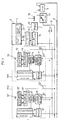
- la figure 1 est un diagramme fonctionnel du dispositif de commande d'alimentation électrique suivant l'invention, et
- la figure 2 est un schéma électrique d'un circuit de couplage interposé entre un circuit de génération de signaux de réveil et le bus de données qui interconnecte les différents modules électroniques formant partie du dispositif suivant l'invention.
- FIG. 1 is a functional diagram of the electrical supply control device according to the invention, and
- FIG. 2 is an electrical diagram of a coupling circuit interposed between a circuit for generating wake-up signals and the data bus which interconnects the various electronic modules forming part of the device according to the invention.
On se réfère à la figure 1 du dessin annexé où il apparaît que le dispositif de commande suivant l'invention comprend plusieurs modules électroniques M1, M2, etc... alimenté par une source d'énergie électrique continue 1 par l'intermédiaire de deux lignes communes 2, 3 respectivement connectées aux bornes positive et négative de la source 1. Dans le cas où le dispositif est embarqué dans un véhicule automobile, la source d'énergie électrique est constituée par la batterie du véhicule. Les lignes 2, 3 constituent ainsi un " bus d'alimentation" sur lequel sont connectés des régulateurs de tension 4, 4′ etc... formant partie chacun d'un des modules M1, M2, respectivement, pour en assurer l'alimentation électrique après réveil dudit module, comme on le verra dans la suite de la présente description.Referring to Figure 1 of the accompanying drawing where it appears that the control device according to the invention comprises several electronic modules M1, M2, etc ... powered by a source of continuous electrical energy 1 via two common lines 2, 3 respectively connected to the positive and negative terminals of the source 1. In the case where the device is on board a motor vehicle, the source of electrical energy is constituted by the vehicle battery. Lines 2, 3 thus constitute a "supply bus" to which voltage regulators 4, 4 ′, etc. are connected, each forming part of one of the modules M1, M2, respectively, to supply it with power. after awakening of said module, as will be seen in the remainder of this description.
Les modules assurent chacun une application particulière. A titre d'exemple, un module électronique peut être associé à un bloc de manettes placé dans un véhicule automobile à proximité du volant, pour permettre au conducteur de commander l'émission d'ordres d'activation/désactivation de divers organes du véhicule. Un autre module peut aussi être associé à un bloc optique du véhicule pour traiter des ordres d'allumage/extinction de phares, de feux de position, etc... Tous les modules sont interconnectés entre eux et avec une unité centrale de traitement de données 5, comme c'est le cas notamment dans un réseau multiplex "de carrosserie" ou de "classe A" où cette unité centralise l'intelligence nécessaire à l'exécution des diverses fonctions de commande de phares, de feux, d'essuie-glaces, d'affichage de données sur un ordinateur de bord, etc....The modules each provide a specific application. For example, an electronic module can be associated with a block of joysticks placed in a motor vehicle near the steering wheel, to allow the driver to control the issuance of activation / deactivation orders of various components of the vehicle. Another module can also be associated with an optical unit of the vehicle to process orders of switching on / off of headlights, position lights, etc. All the modules are interconnected with each other and with a central
Pour l'exécution des fonctions qui lui sont assignées, un module M1, M2 comprend un contrôleur de protocole 6,6′ interposé entre un bus de données 7 commun à tous les modules et à l'unité centrale 5, et des moyens 8,8′ respectivement, constituant chacun un circuit d'application spécifique aux fonctions exécutées (allumage ou extinction d'une ampoule, comptage d'impulsions pour déterminer la distance parcourue et la vitesse du véhicule, etc...).For the execution of the functions assigned to it, a module M1, M2 includes a protocol controller 6,6 ′ interposed between a
Suivant un mode de réalisation préféré de l'invention, le bus de données est un bus à deux lignes (DATA,
Le contrôleur de protocole 6,6′ de chaque module M1, M2, règle les échanges d'informations entre le bus de données et le circuit d'application 8, 8′ associé. Celui-ci peut, à titre d'exemple, être réalisé en logique câblée de très grande intégration (VLSI, suivant la terminologie anglo-saxonne).The protocol controller 6,6 ′ of each module M1, M2, regulates the exchange of information between the data bus and the associated application circuit 8, 8 ′. This can, for example, be performed in very high integration wired logic (VLSI, according to Anglo-Saxon terminology).
Certains modules peuvent être équipés de moyens conçus pour déclencher le réveil de l'ensemble du dispositif, alors que d'autres modules ne sont pas équipés de tels moyens. A titre d'exemple, un module associé au bloc de manettes d'un véhicule automobile, doit être équipé de tels moyens de réveil car c'est dans ce bloc que le conducteur introduit une clé de contact pour commander le démarrage du moteur. La rotation de cette clé doit provoquer le réveil du dispositif, à partir d'un état de veille établi précédemment pour réduire au minimum la consommation électrique du véhicule, pendant un arrêt de celui-ci par exemple. D'autres modules doivent aussi être capables de réveiller le dispositif, par exemple un module associé à un système de défense du véhicule contre des intrusions. L'invention s'intéresse en particulier à l'organisation de modules tels que les modules M1 ou M2.Some modules can be equipped with means designed to trigger the awakening of the entire device, while other modules are not equipped with such means. By way of example, a module associated with the lever block of a motor vehicle must be equipped with such wake-up means because it is in this block that the driver introduces an ignition key to control the starting of the engine. The rotation of this key must cause the device to wake up from a standby state previously established to minimize the power consumption of the vehicle, for example during a standstill thereof. Other modules must also be able to wake up the device, for example a module associated with a vehicle defense system against intrusions. The invention is particularly interested in the organization of modules such as modules M1 or M2.
Dans ces modules, le contrôleur de protocole est interconnecté au bus de données 7 à travers un émetteur-récepteur de ligne 9, 9′, éventuellement associé à filtre 10, 10′, un circuit d'isolement 11, 11′ de l'émetteur-récepteur étant en outre prévu pour un but que l'on expliquera plus loin. Ce dernier circuit est lui-même alimenté par le régulateur de tension 4, 4′, tout comme le contrôleur de protocole 6, 6′.In these modules, the protocol controller is interconnected to the
Les modules M1 et M2 comprennent en outre chacun un circuit de génération de signaux de réveil 12, 12′, respectivement, activés par un moyen de déclenchement tel qu'un interrupteur 13, 13′. Un tel interrupteur peut être fermé par l'introduction d'une clé de contact dans la serrure d'un bloc de manettes d'un véhicule automobile, comme on l'a vu plus haut. L'introduction d'une telle clé étant significative d'une action de mise en marche du véhicule, il faut alors "réveiller" les modules électroniques qui commandent divers actionneurs incorporés à ce véhicule. Suivant l'invention, ce réveil est provoqué par l'émission d'une séquence de signaux engendrés par le circuit de génération 12 et transmis à l'unité centrale 5 par l'intermédiaire d'un circuit de couplage 14 (ou 14′ dans le module M2), d'un circuit de détection 15 et d'un éventuel circuit de filtrage 16.The modules M1 and M2 further each comprise a circuit for generating wake-
Suivant une caractéristique essentielle du dispositif selon l'invention, on réduit la consommation électrique de l'ensemble des modules en période de veille, en coupant l'alimentation de ces modules par le bus d'alimentation 2, 3 et en alimentant alors seulement les circuits nécessaires au réveil de l'ensemble, par l'intermédiaire du bus de données. On peut choisir à cet effet une seule des lignes de ce bus, par exemple la ligne
L'alimentation en période de veille des seuls circuits nécessaires à l'émission et au traitement des signaux de réveil, permet de réduire considérablement la consommation électrique des modules par rapport à celle que l'on observe lorsque tous les modules électroniques sont en activité, (couramment, de 2 à 25 ampères). On peut alors réduire en période de veille, à moins de 3 mA par exemple, la consommation en courant du dispositif, tirée de la batterie du véhicule, consommation qui est considérée comme supportable par celle-ci pendant de longues périodes, correspondant à celles pendant lesquelles le véhicule n'est pas en service.The power supply in standby time of the only circuits necessary for the transmission and processing of the wake-up signals, makes it possible to considerably reduce the electrical consumption of the modules compared to that which is observed when all the electronic modules are active, (commonly, 2 to 25 amps). We can then reduce in standby period, to less than 3 mA for example, the current consumption of the device, drawn from the vehicle battery, consumption which is considered as bearable by it for long periods, corresponding to those during which the vehicle is not in service.
Il faut donc, lorsque le véhicule passe d'une période d'activité à une période d'inactivité, commuter l'alimentation des modules, du bus d'alimentation vers le bus de données. Ce passage peut être facilement détecté par exemple par le retrait de la clé de contact du bloc de manettes. L'unité centrale 5 ainsi prévenue, ouvre un sectionneur 17 qui coupe la connexion de la ligne 2 à la batterie 1 et ferme un interrupteur 18 pour assurer la connexion à la batterie d'un régulateur de tension 19 qui alimente la ligne
Suivant une mise en oeuvre avantageuse de la présente invention, les circuits d'isolement 11, 11′ sont normalement alimentés par les régulateurs 4, 4′ respectivement, pour assurer la transmission d'informations venues du bus de données 7 vers les contrôleurs de protocole 6, 6′ respectivement. A la mise en état de veille du dispositif selon l'invention, l'alimentation de ces circuits est coupée, pour empêcher que du courant venu, en état de veille, de la ligne DATA ne vienne alimenter les contrôleurs de protocole 6, 6′ à travers les émetteur-récepteurs de ligne 9, 9′.According to an advantageous implementation of the present invention, the
L'alimentation du dispositif étant ainsi réglée pour un état de veille, seuls les circuits 12, 12′, 14, 14′, 15 et 16 restent actifs. A la fermeture de l'interrupteur 13 par exemple, significative du fait que l'ensemble des modules doit être réactivé, le circuit 12 alimenté en énergie électrique par une ligne ALIM par l'intermédiaire du circuit de couplage 14, fournit à celui-ci une séquence de signaux "de réveil". Le circuit de couplage 14, qui sera décrit plus loin en détail en liaison avec la figure 2, module alors le courant d'alimentation qu'il reçoit de la ligne
Suivant une caractéristique avantageuse du dispositif selon l'invention, la séquence de signaux émise par le circuit 12 est particulière au module dont elle est originaire et l'unité centrale peut alors identifier ce module par la reconnaissance de la séquence particulière qui lui est attachée. Cette identification donne à l'unité centrale la possibilité de moduler le réveil du dispositif en fonction de l'origine de l'action de réveil, comme on l'a vu plus haut en préambule de la présente description.According to an advantageous characteristic of the device according to the invention, the sequence of signals emitted by the
Un logiciel de "détection de réveil" implanté dans l'unité centrale 5 décode la séquence de signaux reçue de la ligne 20 et commande en retour la fermeture du sectionneur 17 et l'ouverture de l'interrupteur 18, pour rétablir l'alimentation des modules par le bus d'alimentation, comme il convient en fonctionnement normal de ces modules.A software for "awakening detection" installed in the
Pour commander, en sens inverse, le passage de l'alimentation du dispositif en mode "veille", l'unité centrale comprend un autre logiciel conçu pour analyser les signaux multiplexés reçus par le bus de données 7, pour en déduire un éventuel passage à l'état inactif du véhicule et commuter alors l'alimentation de ce dispositif dans la configuration "veille". Pour ce faire, ce logiciel peut être sensible par exemple, à l'absence, pendant un temps prédéterminé, de signaux normalement reçus de certains capteurs ou actionneurs, absence significative d'une inactivité du véhicule. Comme on l'a vu plus haut, le retrait de la clé de contact est une action significative d'un passage à l'état inactif du véhicule qui peut être détecté et interprété en ce sens par le logiciel de "détection de passage en mode veille".To control, in the opposite direction, the passage of the power supply of the device in "standby" mode, the central unit includes other software designed to analyze the multiplexed signals received by the
Ayant ainsi décrit le fonctionnement du dispositif de commande selon l'invention, tant dans son passage en état de veille que dans son réveil à partir d'un tel état, comme suite à une action de réveil détectée par l'interrupteur 13 du module M1, il n'est pas besoin de répéter cette description pour le module M2 qui est composé de circuits identiques à ceux du module M1 et qui fonctionne de même.Having thus described the operation of the control device according to the invention, both in its passage into standby state and in its awakening from such a state, as a result of a wake-up action detected by the
Avant de passer à la description de la structure et du fonctionnement du circuit de couplage 14 introduit entre le circuit 12 et le bus de données 7, il est utile de revenir sur la nature des signaux véhiculés par ce bus de données.Before going on to the description of the structure and operation of the
Suivant une mise en oeuvre avantageuse de la présente invention, on préfère travailler sur ce bus "en courant" plutôt qu'en tension car, dans le milieu fortement perturbé du point de vue électromagnétique que constitue un véhicule automobile, on s'affranchit ainsi de nombre de signaux de tension parasites induits électromagnétiquement dans le bus-par l'environnement. Les informations circulant sur le bus de données sous forme d'impulsions de courant, le rôle des émetteur-récepteurs de ligne est d'assurer une conversion courant/tension de ces impulsions pour les rendre intelligibles aux contrôleurs de protocole et une conversion tension/courant d'un contrôleur vers le bus.According to an advantageous implementation of the present invention, it is preferable to work on this bus "in current" rather than in voltage because, in the medium highly disturbed from the electromagnetic point of view that constitutes a motor vehicle, it thus overcomes number of parasitic voltage signals induced electromagnetically in the bus by the environment. The information circulating on the data bus in the form of current pulses, the role of the line transceivers is to ensure a current / voltage conversion of these pulses to make them intelligible to the protocol controllers and a voltage / current conversion from a controller to the bus.
On remarquera encore que le fait de travailler en courant sur le bus de données permet éventuellement de se passer de l'interrupteur 18. Le bus de données est alors alimenté en permanence par le régulateur de tension, en état de veille ou en fonctionnement normal, ce qui est sans incidence sur la détection des impulsions de courant circulant dans ce bus.It will also be noted that the fact of working with current on the data bus eventually makes it possible to dispense with the
On se réfère à la figure 2 du dessin annexé où on a représenté un schéma d'un circuit de couplage tel que le circuit 14 du module M1. Ce circuit est connecté par une ligne 22 à la ligne 2 du bus d'alimentation reliée au pôle positif de la batterie 1. Le circuit est aussi connecté à la ligne
Le circuit de génération 12 exige une remise à zéro RAZ synchrone avec le passage du dispositif en état de veille. A ce passage, la ligne 22 passe à un niveau de tension bas et ce niveau est transmis à l'entrée RAZ du circuit 12 par une ligne 23, à travers un circuit de filtrage (C1, R2) propre à absorber l'impulsion de tension qui apparaît au démarrage du moteur du véhicule. Des résistances R1 et R7 de charge sont introduites entre la ligne 22 et la ligne 23 d'une part, entre l'entrée du filtre (C1, R2) et la masse d'autre part.The
La ligne 22 est connectée à la ligne ALIM d'alimentation du circuit 12 par l'intermédiaire d'une diode D1. Une diode de Zener Z1, de 10 volts de tension de claquage par exemple, protège le circuit 12 de surtensions sur la ligne 22. Réalisé en technologie CMOS actuelle, le circuit 12 peut supporter des tensions jusqu'à 18 volts. Il est donc bien protégé par la diode de Zener Z1.
Une capacité C2 est placée en parallèle sur la diode Z1, entre l'entrée ALIM du circuit 12 et la masse. La capacité C2 filtre des perturbations transitoires de l'alimentation.A capacitor C2 is placed in parallel on the diode Z1, between the input ALIM of the
En mode veille l'alimentation du circuit 12 est assurée par la ligne
Lorsque le système n'est pas en mode veille, la diode D1 évite que la tension d'alimentation du circuit 12 ne suive la tension de la batterie lorsque celle-ci chute brutalement (lors du démarrage du véhicule par exemple) et assure alors le blocage de la diode D2.When the system is not in standby mode, the diode D1 prevents the supply voltage of
La section de couplage proprement dite du circuit 14 est constituée par un transistor T1, du type NPN par exemple, dont le circuit collecteur-émetteur est connecté entre la ligne
Ainsi la conduction du transistor T1 est-elle modulée par les impulsions de réveil IMP. Le transistor T1 module alors en conformité avec ces impulsions le courant dans la ligne
A titre d'exemple non limitatif, on peut choisir les valeurs des résistances R3, R4 et R5 de manière que le transistor T1 établisse une impulsion de courant de 27 mA d'amplitude dans la ligne
Dans le mode de réalisation envisagé plus haut où la ligne
Il apparaît maintenant que les buts annoncés du dispositif suivant l'invention sont atteints, à savoir :
- limiter la consommation de courant du dispositif en état de veille,
- disposer d'un matériel réalisé avec des circuits numériques dont le fonctionnement ne dépend pas de dérives en température de composants électroniques,
- disposer d'un matériel qui n'exige pas de réglage en fonction du nombre de modules interconnectés dans le dispositif,
- protéger le dispositif des effets de perturbations électriques ou électromagnétiques induites et/ou de variations de la tension de la batterie,
- permettre l'identification du module qui est à l'origine d'un réveil du dispositif.
- limit the current consumption of the device in standby state,
- have equipment made with circuits digital whose operation does not depend on temperature drifts of electronic components,
- have equipment that does not require adjustment based on the number of modules interconnected in the device,
- protect the device from the effects of induced electrical or electromagnetic disturbances and / or variations in the battery voltage,
- allow the identification of the module which is the cause of a wake-up of the device.
Bien entendu l'invention n'est pas limitée au mode de réalisation décrit et représenté qui n'a été donné qu'à titre d'exemple.Of course, the invention is not limited to the embodiment described and shown which has been given only by way of example.
Claims (12)
- A control device for the electrical supply of a plurality of electronic modules (M1, M2) interconnected by a data bus (7) with a central data processing unit (5), of the type comprising a common electrical supply line (2) for the modules, characterised in that it comprises means installed in the central unit (5) and sensitive to a predetermined state of the device in order to control its transition into a waiting state by cutting off the supply to the modules (M1, M2) from the common line (2) and then providing for the electrical supply of at least one re-actuation signal generation circuit (12, 12′) forming part of a module by means of at least one data bus line (DATA), and means (15, 16, 5) sensitive to the re-actuation signals transmitted by the circuit (12, 12′) generating these signals, in order to cut off the supply to the modules from the data bus (7) and to re-establish the supply to the modules from the common electrical supply line (2).
- A device as claimed in claim 1, characterised in that the central unit (5) comprises software means for detecting a waiting state by processing information transmitted from the modules and transmitted to the central unit (5) by the data bus (7).
- A device as claimed in claim 2, characterised in that at least one of the modules comprises means (13, 13′) for selectively triggering an associated re-actuation signal generation circuit (12, 12′), a coupling circuit (14, 14′) associated with this generation circuit for transmitting these signals to the data bus (7) and a detection circuit (15) interposed between the bus (7) and the central unit (5) and sensitive to these signals in order to transmit an instruction to re-actuate the device to the central unit (5).
- A device as claimed in claim 3, characterised in that it comprises a voltage regulator (19) brought into operation by the central unit (5) when the supply to the modules from the common supply line (2) is cut off, in order to supply the detection circuit (12, 12′) and, via the data bus (7), the coupling circuit (14, 14′) and the re-actuation signal generation circuit (12, 12′) of each module equipped with these circuits.
- A device as claimed in any one of claims 3 and 4, characterised in that each of these modules (M1, M2) further comprises a circuit (11, 11′), controlled by the transition to the waiting state of the device, in order to isolate the remainder of the module from the supply then provided by the data bus (7).
- A device as claimed in claim 5, characterised in that each of the modules (M1, M2) comprises a protocol controller (6, 6′) interconnected with the data bus (7) by means of a line transmitter-receiver (9, 9′), the isolation circuit (11, 11′) controlling the actuation or disactivation of this transmitter-receiver (9, 9′).
- A device as claimed in claim 3, characterised in that the re-actuation signal generation circuit (12, 12′) generates a pulse sequence, in that the coupling circuit (14, 14′) comprises a means (T1) for modulating, under the control of this sequence, the current circulating in the line (DATA) of the data bus used for the supply of a part of the module in the waiting state, the detection circuit (12, 12′) being sensitive to this modulated current in order to transmit a re-actuation instruction to the central unit.
- A device as claimed in claim 7, characterised in that the modulation means is a transistor (T1) whose emitter-collector circuit is connected between earth and the line of the data bus (7) acting as a supply line in the waiting state and in that the re-actuation signal generation circuit (12, 12′) controls the base of this transistor (T1) in order to modulate the current in this line.
- A device as claimed in claim 8, characterised in that the pulse sequence transmitted by a module is specific thereto and in that the central unit (5) comprises means for identifying the module transmitting the sequence from the signals (IMP) received from the detection circuit (12, 12′).
- A device as claimed in any one of claims 3 to 9, characterised in that the coupling circuit (14, 14′) is sensitive to the discontinuation of the supply from the common line (2) in order to control the initialisation of the re-actuation signal generation circuit (12, 12′).
- A device as claimed in any one of claims 3 to 10, characterised in that the means for selectively triggering a re-actuation signal generation circuit (12, 12′) is formed by a switch (13, 13′) whose switching controls the excitation of this circuit and in that the switching of this switch is triggered by an action indicative of a re-actuation of the device.
- A device as claimed in claim 11, adapted to be installed in an automobile vehicle, characterised in that the switch (13, 13′) is switched by the insertion of a contact key into a lock, prior to the starting of the vehicle.
Applications Claiming Priority (2)
| Application Number | Priority Date | Filing Date | Title |
|---|---|---|---|
| FR9002570A FR2659155B1 (en) | 1990-03-01 | 1990-03-01 | DEVICE FOR CONTROLLING THE ELECTRICAL SUPPLY OF A PLURALITY OF ELECTRONIC MODULES. |
| FR9002570 | 1990-03-01 |
Publications (2)
| Publication Number | Publication Date |
|---|---|
| EP0444997A1 EP0444997A1 (en) | 1991-09-04 |
| EP0444997B1 true EP0444997B1 (en) | 1995-02-01 |
Family
ID=9394273
Family Applications (1)
| Application Number | Title | Priority Date | Filing Date |
|---|---|---|---|
| EP91400432A Expired - Lifetime EP0444997B1 (en) | 1990-03-01 | 1991-02-19 | Circuit for controlling the power supply of a plurality of electronic modules |
Country Status (4)
| Country | Link |
|---|---|
| EP (1) | EP0444997B1 (en) |
| DE (1) | DE69107100T2 (en) |
| ES (1) | ES2067880T3 (en) |
| FR (1) | FR2659155B1 (en) |
Cited By (11)
| Publication number | Priority date | Publication date | Assignee | Title |
|---|---|---|---|---|
| US7779026B2 (en) | 2002-05-03 | 2010-08-17 | American Power Conversion Corporation | Method and apparatus for collecting and displaying network device information |
| US7986224B2 (en) | 2003-04-14 | 2011-07-26 | American Power Conversion Corporation | Environmental monitoring device |
| US8005944B2 (en) | 1999-10-27 | 2011-08-23 | American Power Conversion Corporation | Method and system for monitoring computer networks and equipment |
| US8015255B2 (en) | 2003-10-27 | 2011-09-06 | American Power Conversion Corporation | System and method for network device communication |
| US8224953B2 (en) | 1999-10-27 | 2012-07-17 | American Power Conversion Corporation | Method and apparatus for replay of historical data |
| US8271626B2 (en) | 2001-01-26 | 2012-09-18 | American Power Conversion Corporation | Methods for displaying physical network topology and environmental status by location, organization, or responsible party |
| US8566292B2 (en) | 2003-04-14 | 2013-10-22 | Schneider Electric It Corporation | Method and system for journaling and accessing sensor and configuration data |
| US8990536B2 (en) | 2011-06-01 | 2015-03-24 | Schneider Electric It Corporation | Systems and methods for journaling and executing device control instructions |
| US9952103B2 (en) | 2011-12-22 | 2018-04-24 | Schneider Electric It Corporation | Analysis of effect of transient events on temperature in a data center |
| US11076507B2 (en) | 2007-05-15 | 2021-07-27 | Schneider Electric It Corporation | Methods and systems for managing facility power and cooling |
| FR3137512A1 (en) * | 2022-07-04 | 2024-01-05 | Stmicroelectronics (Rousset) Sas | Powering an electronic device |
Families Citing this family (16)
| Publication number | Priority date | Publication date | Assignee | Title |
|---|---|---|---|---|
| DE4125860C1 (en) * | 1991-08-03 | 1992-08-06 | Robert Bosch Gmbh, 7000 Stuttgart, De | |
| JP2949998B2 (en) * | 1992-02-21 | 1999-09-20 | 日産自動車株式会社 | Communication device |
| US5389952A (en) * | 1992-12-02 | 1995-02-14 | Cordata Inc. | Low-power-consumption monitor standby system |
| US5821924A (en) * | 1992-09-04 | 1998-10-13 | Elonex I.P. Holdings, Ltd. | Computer peripherals low-power-consumption standby system |
| FR2701325B1 (en) * | 1993-02-05 | 1995-03-10 | Renault | Data transmission bus isolation device. |
| JP3136926B2 (en) * | 1994-11-08 | 2001-02-19 | 松下電器産業株式会社 | Storage battery status management system |
| EP1266803B1 (en) | 1995-05-24 | 2003-10-22 | Hitachi, Ltd. | Car electronic control system & method for controlling the same |
| EP0906524A1 (en) * | 1997-04-01 | 1999-04-07 | Robert Bosch Gmbh | System for operating a control device in a motor vehicle |
| DE19715880C1 (en) * | 1997-04-16 | 1998-07-23 | Mc Micro Compact Car Ag | System of wire bus networked controllers with reduced residual current consumption |
| DE19853451B4 (en) * | 1998-11-19 | 2007-06-14 | Robert Bosch Gmbh | Method for deactivating a network component network, in particular a motor vehicle network component network |
| DE10031891A1 (en) | 2000-06-30 | 2002-01-10 | Bosch Gmbh Robert | Method for operating a device connected to a vehicle communication network |
| FR2911442B1 (en) | 2007-01-16 | 2015-05-15 | Airbus France | POWER SUPPLY SYSTEM AND METHOD FOR ACTUATORS ON BOARD AN AIRCRAFT |
| FR2916709A3 (en) * | 2007-06-04 | 2008-12-05 | Renault Sas | Electric units set e.g. radio receiving set, electric supply control method for motor vehicle, involves shifting from sleep mode to active mode by detection of presence of user, and shifting from active to sleep mode when user is absent |
| CN101950281B (en) * | 2010-07-06 | 2015-11-25 | 无锡中星微电子有限公司 | A kind of method and apparatus controlling coprocessor |
| FR3043961B1 (en) * | 2015-11-23 | 2017-11-17 | Continental Automotive France | METHOD FOR MANAGING THE POWER SUPPLY OF AN ELECTRONIC CONTROL UNIT DURING THE STARTING PHASE OF A MOTOR VEHICLE |
| FR3047573B1 (en) * | 2016-02-10 | 2018-03-02 | Continental Automotive France | METHOD FOR VOLTAGE CONTROL OF MOUNTED EQUIPMENT IN A MOTOR VEHICLE |
Family Cites Families (5)
| Publication number | Priority date | Publication date | Assignee | Title |
|---|---|---|---|---|
| FR2445769A1 (en) * | 1979-01-04 | 1980-08-01 | Renault | Motor vehicle electrical supply system - includes central control sending signals to microprocessors which switch on required accessories |
| US4661718A (en) * | 1984-06-07 | 1987-04-28 | Nippondenso Co., Ltd. | Information and electrical power transmission system and method for vehicle |
| US4639609A (en) * | 1985-02-26 | 1987-01-27 | United Technologies Automotive, Inc. | Load current management system for automotive vehicles |
| FR2578067B1 (en) * | 1985-02-27 | 1988-04-15 | Renault | CONTROLLED ELECTRIC POWER DISTRIBUTION SYSTEM IN A MOTOR VEHICLE |
| FR2626998B1 (en) * | 1988-02-05 | 1990-08-03 | Bendix Electronics Sa | OPERATIONAL AND STANDBY SYSTEM FOR ELECTRONIC BOXES CONNECTED TO A COMMUNICATION CHANNEL |
-
1990
- 1990-03-01 FR FR9002570A patent/FR2659155B1/en not_active Expired - Fee Related
-
1991
- 1991-02-19 DE DE69107100T patent/DE69107100T2/en not_active Expired - Fee Related
- 1991-02-19 ES ES91400432T patent/ES2067880T3/en not_active Expired - Lifetime
- 1991-02-19 EP EP91400432A patent/EP0444997B1/en not_active Expired - Lifetime
Cited By (18)
| Publication number | Priority date | Publication date | Assignee | Title |
|---|---|---|---|---|
| US8024451B2 (en) | 1999-10-27 | 2011-09-20 | American Power Conversion Corporation | Method and system for monitoring computer networks and equipment |
| US8224953B2 (en) | 1999-10-27 | 2012-07-17 | American Power Conversion Corporation | Method and apparatus for replay of historical data |
| US8090817B2 (en) | 1999-10-27 | 2012-01-03 | American Power Conversion Corporation | Method and system for monitoring computer networks and equipment |
| US8005944B2 (en) | 1999-10-27 | 2011-08-23 | American Power Conversion Corporation | Method and system for monitoring computer networks and equipment |
| US8966044B2 (en) | 2001-01-26 | 2015-02-24 | Schneider Electric It Corporation | Methods for displaying physical network topology and environmental status by location, organization, or responsible party |
| US8271626B2 (en) | 2001-01-26 | 2012-09-18 | American Power Conversion Corporation | Methods for displaying physical network topology and environmental status by location, organization, or responsible party |
| US8719319B2 (en) | 2002-05-03 | 2014-05-06 | Schneider Electric It Corporation | Method and apparatus for collecting and displaying network device information |
| US7958170B2 (en) | 2002-05-03 | 2011-06-07 | American Power Conversion Corporation | Method and apparatus for collecting and displaying data associated with network devices |
| US8019798B2 (en) | 2002-05-03 | 2011-09-13 | American Power Conversion Corporation | Method and apparatus for collecting and displaying network device information |
| US7779026B2 (en) | 2002-05-03 | 2010-08-17 | American Power Conversion Corporation | Method and apparatus for collecting and displaying network device information |
| US7986224B2 (en) | 2003-04-14 | 2011-07-26 | American Power Conversion Corporation | Environmental monitoring device |
| US8566292B2 (en) | 2003-04-14 | 2013-10-22 | Schneider Electric It Corporation | Method and system for journaling and accessing sensor and configuration data |
| US8015255B2 (en) | 2003-10-27 | 2011-09-06 | American Power Conversion Corporation | System and method for network device communication |
| US11076507B2 (en) | 2007-05-15 | 2021-07-27 | Schneider Electric It Corporation | Methods and systems for managing facility power and cooling |
| US11503744B2 (en) | 2007-05-15 | 2022-11-15 | Schneider Electric It Corporation | Methods and systems for managing facility power and cooling |
| US8990536B2 (en) | 2011-06-01 | 2015-03-24 | Schneider Electric It Corporation | Systems and methods for journaling and executing device control instructions |
| US9952103B2 (en) | 2011-12-22 | 2018-04-24 | Schneider Electric It Corporation | Analysis of effect of transient events on temperature in a data center |
| FR3137512A1 (en) * | 2022-07-04 | 2024-01-05 | Stmicroelectronics (Rousset) Sas | Powering an electronic device |
Also Published As
| Publication number | Publication date |
|---|---|
| DE69107100D1 (en) | 1995-03-16 |
| EP0444997A1 (en) | 1991-09-04 |
| FR2659155B1 (en) | 1992-05-29 |
| FR2659155A1 (en) | 1991-09-06 |
| DE69107100T2 (en) | 1995-09-14 |
| ES2067880T3 (en) | 1995-04-01 |
Similar Documents
| Publication | Publication Date | Title |
|---|---|---|
| EP0444997B1 (en) | Circuit for controlling the power supply of a plurality of electronic modules | |
| EP0327456B1 (en) | System for putting electronic packages connected to a communication channel in an operative and in a standby position | |
| EP0435738B1 (en) | Electronic stations network monitoring procedure and network obtained, especially for motor vehicles | |
| EP0275789B1 (en) | Anti-theft device with adjustable code for automotive vehicles | |
| EP0694664A1 (en) | Arrangement comprising an electric door lock with an electrical emergency function and its control and supply means | |
| FR2736600A1 (en) | ELECTRONIC CONTROL APPARATUS FOR A MOTOR VEHICLE HAVING COMPUTER NETWORKS AND AN IMMOBILIZER DEVICE | |
| CA2405333C (en) | Method for managing the operating conditions of an anti-theft security device for a motor vehicle and device therefor | |
| FR2576568A1 (en) | ANTI-THEFT DEVICE, IN PARTICULAR FOR AUTOMOTIVE VEHICLES | |
| FR2545632A1 (en) | Anti-theft system comprising a main device and an "annex to be protected" element | |
| EP0582523A1 (en) | Electronic antitheft system for a motor vehicle | |
| EP1963933A2 (en) | Electronic device for commutation of electric load controlled by a microcontroller | |
| EP3615379A1 (en) | On-board system for a motor vehicle intended to power and control the lights of a connected trailer | |
| FR2720703A1 (en) | Key operated anti-theft system for motor vehicle | |
| EP0239463B1 (en) | Device for the electrical supply of a central unit, connected to a least one local reception station, by at least one command signal | |
| EP1046557B1 (en) | Access authorization system for a vehicle | |
| EP0730072B1 (en) | Arrangement comprising an electric door lock with an electrical emergency function and its control means | |
| EP0921306B1 (en) | Control device for an automotive vehicle starter | |
| WO1994015817A1 (en) | Interactive universal security device for motor vehicles | |
| FR2583688A1 (en) | Security equipment preventing non-authorised use or theft of a motor vehicle. | |
| EP0358544A2 (en) | Method and device for automatically activating the alarm system, in particular for an automobile | |
| FR3039903B1 (en) | HANDS-FREE ACCESS AND START SYSTEM OF A MOTOR VEHICLE | |
| FR2653920A1 (en) | Alarm system especially for a motor vehicle, with an independent electrical energy source | |
| FR2736317A1 (en) | ANTI-THEFT SYSTEM FOR A MOTOR VEHICLE | |
| FR2825960A1 (en) | Hands free car starter system switches shared components to immobilization mode | |
| FR2778883A1 (en) | Security system for vehicles and motor cycles designed to counter theft involving menaces |
Legal Events
| Date | Code | Title | Description |
|---|---|---|---|
| PUAI | Public reference made under article 153(3) epc to a published international application that has entered the european phase |
Free format text: ORIGINAL CODE: 0009012 |
|
| AK | Designated contracting states |
Kind code of ref document: A1 Designated state(s): DE ES GB IT |
|
| 17P | Request for examination filed |
Effective date: 19920211 |
|
| 17Q | First examination report despatched |
Effective date: 19940321 |
|
| GRAA | (expected) grant |
Free format text: ORIGINAL CODE: 0009210 |
|
| AK | Designated contracting states |
Kind code of ref document: B1 Designated state(s): DE ES GB IT |
|
| ITF | It: translation for a ep patent filed |
Owner name: JACOBACCI & PERANI S.P.A. |
|
| GBT | Gb: translation of ep patent filed (gb section 77(6)(a)/1977) |
Effective date: 19950215 |
|
| REF | Corresponds to: |
Ref document number: 69107100 Country of ref document: DE Date of ref document: 19950316 |
|
| REG | Reference to a national code |
Ref country code: ES Ref legal event code: FG2A Ref document number: 2067880 Country of ref document: ES Kind code of ref document: T3 |
|
| PLBE | No opposition filed within time limit |
Free format text: ORIGINAL CODE: 0009261 |
|
| STAA | Information on the status of an ep patent application or granted ep patent |
Free format text: STATUS: NO OPPOSITION FILED WITHIN TIME LIMIT |
|
| 26N | No opposition filed | ||
| REG | Reference to a national code |
Ref country code: GB Ref legal event code: IF02 |
|
| PGFP | Annual fee paid to national office [announced via postgrant information from national office to epo] |
Ref country code: ES Payment date: 20080206 Year of fee payment: 18 |
|
| PGFP | Annual fee paid to national office [announced via postgrant information from national office to epo] |
Ref country code: IT Payment date: 20080213 Year of fee payment: 18 |
|
| PGFP | Annual fee paid to national office [announced via postgrant information from national office to epo] |
Ref country code: DE Payment date: 20090227 Year of fee payment: 19 |
|
| PGFP | Annual fee paid to national office [announced via postgrant information from national office to epo] |
Ref country code: GB Payment date: 20090128 Year of fee payment: 19 |
|
| REG | Reference to a national code |
Ref country code: ES Ref legal event code: FD2A Effective date: 20090220 |
|
| PG25 | Lapsed in a contracting state [announced via postgrant information from national office to epo] |
Ref country code: ES Free format text: LAPSE BECAUSE OF NON-PAYMENT OF DUE FEES Effective date: 20090220 |
|
| GBPC | Gb: european patent ceased through non-payment of renewal fee |
Effective date: 20100219 |
|
| PG25 | Lapsed in a contracting state [announced via postgrant information from national office to epo] |
Ref country code: DE Free format text: LAPSE BECAUSE OF NON-PAYMENT OF DUE FEES Effective date: 20100901 |
|
| PG25 | Lapsed in a contracting state [announced via postgrant information from national office to epo] |
Ref country code: IT Free format text: LAPSE BECAUSE OF NON-PAYMENT OF DUE FEES Effective date: 20090219 Ref country code: GB Free format text: LAPSE BECAUSE OF NON-PAYMENT OF DUE FEES Effective date: 20100219 |