EP0444525B1 - Network and method for transferring data between a programmable controller and a plurality of processing units - Google Patents
Network and method for transferring data between a programmable controller and a plurality of processing units Download PDFInfo
- Publication number
- EP0444525B1 EP0444525B1 EP91102500A EP91102500A EP0444525B1 EP 0444525 B1 EP0444525 B1 EP 0444525B1 EP 91102500 A EP91102500 A EP 91102500A EP 91102500 A EP91102500 A EP 91102500A EP 0444525 B1 EP0444525 B1 EP 0444525B1
- Authority
- EP
- European Patent Office
- Prior art keywords
- data link
- instruction
- instructions
- operation completion
- information
- Prior art date
- Legal status (The legal status is an assumption and is not a legal conclusion. Google has not performed a legal analysis and makes no representation as to the accuracy of the status listed.)
- Expired - Lifetime
Links
Images


Classifications
-
- G—PHYSICS
- G06—COMPUTING; CALCULATING OR COUNTING
- G06F—ELECTRIC DIGITAL DATA PROCESSING
- G06F9/00—Arrangements for program control, e.g. control units
- G06F9/06—Arrangements for program control, e.g. control units using stored programs, i.e. using an internal store of processing equipment to receive or retain programs
- G06F9/46—Multiprogramming arrangements
- G06F9/54—Interprogram communication
Definitions
- the invention relates to a network and a method for transferring data between a programmable controller and a plurality of processing units.
- a network and method for transferring data between such entities is hereinafter described with respect to fig. 6 to 9.
- Fig. 6 is a block diagram illustrating a master station 1 containing a programmable controller 2, employing a conventional PC controlling process, and slave stations 3 and 13, comprising coding devices, readers and the like.
- Processing units 4 and 14 are provided in the slave stations 3 and 13, respectively, and may be in the master station 1 as well.
- a cable 5 links the master station 1 to its adjacent slave stations and links adjacent slave stations to each other.
- a sequence program memory 6 is used for storing a sequence program, a flag memory 7 for storing a variety of flags, and a system program memory 11 for storing a system program required to execute the sequence program.
- a data link instruction information area 8 e.g., a data link instruction information memory, is used for storing the contents of data link instructions for effecting data transfer between the programmable controller 2 and the processing units linked therewith, e.g., data link instruction information and addresses for storing flags that are set when the operation of each of these data link instructions are complete, e.g., operation completion flag addresses, as a set in order.
- a communication control data area 9 is used for temporarily storing together information concerned with each processing unit as communication control data, including the information stored in the data link instruction information area 8, for the purpose of communication control.
- the data link instruction information area 8 and the communication control data area 9 are provided in the system program memory 11.
- Fig. 7 illustrates a sequence program for setting a flag M20 (not illustrated) provided for indicating the completion of all operations of a series of data link instructions executed for a multiple of processing units in the conventional programmable controller control method.
- steps S701 to S720 are steps for executing a series of the data link instructions and a series of operation completion flag addressing instructions for specifying flag addresses to be temporarily set when the respective operations of the series of data link instructions are complete.
- a communication command flag 701 is employed as a flag that is set when the series of ten data link instructions and the series of operation completion flag addressing instructions are executed.
- flags M0 (702) to M9 (711) are set by the series of operation completion flag addressing instructions. These flags are automatically reset after they have been set and the sequence program is run once.
- a set of instructions 734-743 for setting flags M10 (760) to M19 (769) are provided in correspondence with flags M0 (702) to M9 (711), and flags M10 (760) to M19 (769) remain set until flag RESET instructions, discussed later, are executed.
- a flag SET instruction 744 which specifies a flag address M20A and is executed when flags M10 (760) to M19 (769) are all set, sets flag M20 (not illustrated) for indicating that the operations of the entire series of data link instructions is complete.
- flag RESET instructions which reset flags M10 (760) to M19 (769). These instructions are executed when the same conditions exist as those for the execution of step S731, i.e. flags M10 (760) to M19 (769) are all set.
- Fig. 8 illustrates part of the memory contents of the link instruction information area 8 shown in Fig. 6.
- a first data link instruction 801 is composed of information included in the data link instructions that are employed for data transfer to and from a first processing unit 4 and are written in the sequence program, e.g., the processing unit number as a transfer source or destination, a memory address as a transfer source or destination, etc.
- An operation completion flag address 802, specified by the operation completion flag addressing instruction, is written subsequent to the data link instruction in the sequence program.
- the data link instruction information 801 and the operation completion flag address 802 are employed as a set and comprise a "data link instruction-related information group" 821 used for data transfer to and from the first processing unit 4.
- Figure 7 illustrates the execution of a single data link instruction for each processing unit
- multiple data link instructions for each unit may be executed.
- Fig. 9 illustrates a sequence program employing the conventional programmable PC process where several data link instructions (four in Fig. 9) are executed for the same processing unit 4.
- flag 901 at step S901 is a communication command flag, stored in the flag memory 7, that is accompanied by a first data link instruction 902, executed when the communication command flag 901 is set.
- an operation completion flag addressing instruction 902 specifies an address M30A for storing a flag M30 (911) that is set when the operation of the first data link instruction 902 is complete.
- a second data link instruction 903 is executed subsequent to the first data link instruction 902.
- the second data link instruction 903 is executed when flag M30 (911), stored at the address M30A specified at step S902, is set.
- an operation completion flag addressing instruction 907 specifies an address M31A for storing a flag M31 (912) that is set when the operation of data link instruction 903 is complete.
- Third and fourth data link instructions 904 and 905, at steps S905 to S908 are instructions for performing operations similar to those effected by the second data link instruction 903 at steps S903 and S904.
- a flag SET instruction 910 specifies an address M50A and is executed when the operation of the fourth data link instruction 905 is complete at step S907.
- a flag M33 (914) is set for setting a flag M50 (not illustrated) for indicating that the operations of the first data link instruction 902 to fourth data link instruction 905 for unit 4 are all complete.
- M0A is specified as a memory address for storing operation completion flag M0 (702), which is set as the sequence program is run once.
- steps S703 to S720 the operations of the instructions used for the second processing unit 14 through tenth processing unit (units 3-10 are not illustrated in Fig. 6) are performed in correspondence with those of the data instruction 712 and the operation completion flag addressing instruction 722, specifying address M0A, employed for the first processing unit 4 at steps S701 and S702.
- flags M11 (761) to M19 (769) related to the second processing unit 14 through the tenth processing unit are set in the same manner that flag M10 (760), related to the first processing unit 4, was set at step S721.
- FLAG SET instruction 744 is executed to set flag M20 (not illustrated). This stores the fact that the operation of the data link instruction 712 for transfer to or from the first processing unit 4 through the operation of the data link instruction 721 for data transfer to or from the last processing unit (not illustrated) are all complete.
- M0A is employed as the address of flag M0 (702) and is written to the data link instruction information area 8 as the operation completion flag address 802 in Fig. 8.
- steps S703 to S720 the operation performed for the first processing unit 4 at steps S701 and S702 is effected in a similar manner for the second processing unit 14 to the tenth processing unit, and the data link instruction-related information 822 for the second processing unit 14 through the data link instruction-related information 830 for the tenth processing unit are written to the data link instruction information area 8. While the sequence program is run repeatedly, the information is written to the data link instruction information area 8 only once after the communication command flag 701 is set.
- a control part (not illustrated) included in the second processing unit 14 checks the contents of the communication control data area 9 and data link instruction information area 8. If the operation performed immediately beforehand for processing unit 4 is already complete and there is data link instruction-related information which can be started for processing unit 14, a start is effected. When an interrupt signal that occurs periodically at a predetermined period of time is generated, a data transfer is effected to and from processing unit 14 in accordance with the communication control data stored in the communication control data area 9.
- the information related to the data link instruction for unit 4 which has already completed its operation and terminated the operation of holding the corresponding operation completion flag in the set state while the sequence program is executed once, is erased from the data link instruction information area 8. This process is applied correspondingly to each of the remaining processing units.
- operation completion flag addressing instructions 722 to 731 specifying the addresses of flags M0 to M9, must be written in the sequence program in correspondence with each of the data link instruction 712, for data transfer to or from the processing unit 4, through the data link instruction 721, for data transfer to or from the processing unit 10 (not illustrated).
- Instructions 722 to 731 are used to set flag M20 (not illustrated).
- Flag M20 indicates whether or not the operations of the data link instruction 712 for data transfer to or from the first processing unit 4 through the data link instruction 721 for data transfer to or from the tenth processing unit (not illustrated) are all complete.
- flags M0 (702) to M9 (711) specified by operation completion flag addressing instructions for flags M0 (722) to flags M9 (731) are only set as the sequence program is run once, flags M10 (760) to M19 (769) must be provided in correspondence with flags M0 (702) to M9 (711), and steps S721 to S730 are all required in order to store the fact that any one of the flags M0 (702) to M9 (711) has been set while the sequence program is running once. Furthermore, step S731, for setting flag M20 (not illustrated) when all flags M10 (760) to M19 (769) have been set, must be provided.
- sequence program for resetting flags M10 (760) to M19 (769) that previously have been set, must be provided; and, a sequence program, for resetting flags M10 (760) to M19 (769) at steps S732 to S741, must be written.
- Fig. 9 illustrates a sequence program for executing a plurality of data link instructions composed of a first data link instruction 902 to fourth data link instruction 905 for the same processing unit, wherein each subsequent data link instruction is allowed to be executed only after completion of the operation of the data link instruction currently being executed. Therefore, the sequence program must be written so that only when the operation completion flag of the data link instruction executed immediately beforehand is set, can the operation of the next data link instruction be started. As illustrated in Fig. 7, it is also necessary to program the operation completion flag addressing instructions Mn (where n is an integer) in correspondence with respective data link instructions l (where l is an integer).
- the sequence program cannot be written easily.
- an operation completion flag addressing instruction 722-731 for specifying the address for storing the operation completion flag for each of the multiple instructions must be written in the sequence program in addition to the multiple instructions 712-721. This additional effort is time consuming and inefficient.
- an object of the present invention to provide a network and a method that allow a programming of a programmable controller means for transferring data with ease.
- This object is solved by a network of claim 1 and a method of claim 9.
- the programmable controller controlling process of the present invention does not require an operation completion flag addressing instruction to be written for each of the multiple instructions.
- the present invention in one aspect concerns a method for controlling a programmable controller provided in a master station for running a sequence program, including plural data link instructions for effecting data transfer between the programmable controller and processing units, provided in the master station or in slave stations linked with the master station, and an operation completion flag addressing instruction for specifying operation completion flag addresses employed as addresses for storing an operation completion flag set on completion of the operations of said multiple data link instructions.
- the invention comprises a step of transferring the contents of the multiple data link instructions and the operation completion flag addresses to a data link instruction information memory having a memory area for storing the contents of the multiple data link instructions, a memory area for storing the operation completion flag addresses, and a memory area for storing data link instruction operating condition information provided in correspondence with each of the multiple data link instructions and including information on whether or not the operations of the data link instructions are complete. It further comprises a step of executing the multiple data link instructions and setting the operation completion flag when all of said data link instruction operating condition information corresponding to the multiple data link instructions have shown operation completion conditions, while concurrently updating the data link instruction operating condition information serially in accordance with the information stored in the data link instruction information memory.
- the programmable controller runs a sequence program, including a multiple of data link instructions and an operation completion flag addressing instruction for specifying operation completion flag addresses employed as addresses for storing an operation completion flag set on completion of the operations of said multiple data link instructions
- the contents of the multiple data link instructions and the operation completion flag addresses are transferred to a data link instruction information memory having a memory area for storing the contents of the multiple data link instructions, a memory area for storing the operation completion flag addresses, and a memory area for storing data link instruction operating condition information provided in correspondence with each of the multiple data link instructions, and including information on whether or not the operations of the data link instructions are complete.
- the multiple data link instructions are executed and the operation completion flag is set when all of the data link instruction operating condition information corresponding to the multiple data link instructions have shown operation completion conditions, while concurrently the data link instruction operating condition information is updated serially in accordance with the information stored in the data link instruction information memory.
- Fig. 1 is an overall configuration block diagram illustrating a master station and slave stations to which one embodiment of the present invention applies.
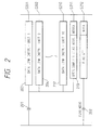
- Fig. 2 shows a sequence program example according to one embodiment of the present invention for executing data link instructions for a plurality of processing units and setting an operation completion flag on completion of all the operations of the data link instructions for the multiple processing units.
- Fig. 3 illustrates information stored in a data link instruction information area in one embodiment of the present invention.
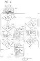
- Fig. 4 is a flowchart illustrating how the operation completion flag is set in one embodiment of the present invention.
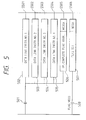
- Fig. 5 shows a sequence program example according to one embodiment of the present invention for executing a plurality of data link instructions for the same processing unit and setting an operation completion flag on completion of all the operations of the multiple data link instructions for that processing unit.
- Fig. 6 is an overall configuration block diagram illustrating a master station and slave stations to which the conventional programmable controller controlling process applies.
- Fig. 7 illustrates a sequence program in the conventional programmable controller controlling process.
- Fig. 8 illustrates a data link instruction information area in the conventional programmable controller controlling process.
- Fig. 9 illustrates a sequence program in the conventional programmable controller controlling process.
- Fig. 1 illustrates an overall configuration of a master station employing one embodiment of the present invention and slave stations linked therewith.
- Element 8 is similar to the one shown in Fig. 8, but differs in that it has additional data link instruction operating condition information 302, 305, 308, ... 329, as shown in Fig. 3.
- An instruction block operation completion processing program area 10 is used to store an instruction block operation completion processing program having a function to set one operation completion flag automatically when the operation of a series of data link instructions in a sequence program are complete. If the series of data link instructions and the operation completion flag addressing instruction have been written in the sequence program, it is only needed to store into appropriate operation completion flag addresses information on whether or not the operations of the series of data link instructions are complete.
- Fig. 2 illustrates a sequence program for use in the programmable controller controlling process according to one embodiment of the present invention.
- the illustrated program corresponds to the sequence program employed in the conventional programmable controller controlling process shown in Fig. 7.
- steps S201 to S211 are executed when a communication command flag 201 is set, data link instructions for effecting data transfer to or from a first processing unit 4 through a tenth processing unit (units 3-10 are not illustrated in Figure 1) are executed at steps S201 to S210, and the address M200A of an operation completion flag set on completion of all operations of steps S201 to S210 is specified at step S211. Since the operation completion flag M200 (202) specified by the operation completion flag address M200A is only set when the sequence program is executed once, after the operations of steps S201 to S210 are all complete, flag M20 (not illustrated) specified at flag address M20A is set at step S212 to store the fact that flag M200 (202) has been set. The presence of an identical operation completion flag at each instruction for a common processing unit permits an efficient execution of all related instructions for that unit.
- the data link instruction information 301 e.g., a processing unit number as a transfer source or destination (1 in this case) and a memory address as a transfer source or destination, when the communication command flag 201 is set.
- the operation performed for the first processing unit 4 at step S201 is effected in a similar manner for the second processing unit 14 to the tenth processing unit.
- data link instruction-related information 332 for data transfer to or from the second processing unit 14 through data link instruction-related information 340 for data transfer to or from the tenth processing unit are written to the data link instruction information area 8.
- the sequence program is run repeatedly, the information is only written to the data link instruction information area 8 once, after the communication command flag 201 has been set, as in the conventional programmable controller controlling process.
- Zeroes are first written to all operation completion flag addresses 303, 306, 309, ... 327. Thereafter, the content of flag address M200A, written at step S211 in Fig. 2, is transferred to operation completion flag address 330. Subsequently, an instruction block operation completion processing program is executed to set all of the remaining operation completion flag addresses, e.g., 303, 306, 309, ... 327, to M200.
- a control part (not illustrated) included in the programmable controller 2 checks the contents of the communication control data area 9 and data link instruction information area 8 every time the sequence program is executed once. If the operation performed for the immediately preceding processing unit is already complete and there is data link instruction-related information which can be started, a start is effected. When an interrupt signal occurring every predetermined period of time is generated, data transfer is made to and from the corresponding data unit in accordance with the communication control data stored in the communication control data area 9.
- Data link instruction operating condition information 302, 305, 308, ... 329, shown in Fig. 3, retains coded operating conditions of the data transfer to and from the corresponding processing units in continuously updated states, based on the corresponding data link instruction information.
- Fig. 4 is a flowchart illustrating the operation completion flag set processing operation performed each time the sequence program is run once.
- the operation is intended to keep track of the completion of the programmed instructions for each of the data links and is generally performed as follows.
- the control part (not illustrated) of the programmable controller 2 reads the data link instruction-related information sequentially from the data link instruction information area 8 and checks for any of the series of data link instruction-related information having the same operation completion flag address (i.e., where multiple instructions are performed for multiple units and have been given a single operating completion flag address, as described with respect to Fig. 3), that has not completed its operation.
- control part completes the series of data link instruction-related information. If there is no information that has not yet completed all of its operation in the series of data link instruction-related information having the same operation completion flag address, i.e. forming the same ladder block, the control area erases the series of data link instruction-related information having the same operation completion flag address from the data link instruction information area 8 and sets the corresponding operation completion flag.
- step S401 data link instruction-related information stored at the first address of the data link instruction information area 8 is read.
- step S402 the contents of the data link instruction operating condition information are checked. If the operation based on the data link instruction-related information is not yet complete, the execution progresses to step S403 to check whether or not the next data link instruction-related information is present. If there is no such information written, the operation completion flag set processing operation is terminated at step S413 without any further processing. If the next data link instruction-related information exists, the execution advances to the next step S404 and reads this data link instruction-related information.
- Step S405 determines whether or not the read operation completion flag address is identical to the previously read address. If identical, the execution returns to step S403, judging it as data link instruction-related information corresponding to the previously executed data link instruction and forming part of a series of instructions with the same operation completion flag address.
- step S402 If the operation completion flag address is different from that just read previously, the execution returns to step S402, judging it as different from the data link instruction-related information corresponding to the previously executed data link instruction and as not forming part of a series of instructions with the same operation completion flag address.
- Steps S403 to S405 are steps for skipping the data link instruction-related information having the same operation completion flag address that has not yet completed the operation, if such information exists in the data link instruction information area 8. This skipping procedure permits an execution of the program in a manner more efficient than that of the conventional process.
- Step S402 checks the data link instruction operating condition information of the read data link instruction-related information. If the operation is complete, the execution proceeds to step S406. If the next data link instruction-related information to be read does not exist in the data link instruction information area 8 at step S406, e.g., if information 332 of Fig. 3 did not exist, the execution progresses to step S407, determining that the data transfer processing based on the data link instruction-related information stored in the data link instruction information area 8 has been terminated.
- the operation completion flag stored at the operation completion flag address is set while the sequence program is run once. This can store the fact that the operations of the data link instructions, which were read previously in a series and have identical operation completion flag addresses, are all complete.
- step S408 the data link instruction-related information, which may correspond to a series of data link instructions having identical operation completion flag addresses, is erased from the data link instruction information area 8 and the operation completion flag set processing operation is terminated.
- step S406 if the next data link instruction-related information, e.g., information 332, is present in the data link instruction information area 8, the execution advances to step S409, reads the data link instruction-related information, e.g., information 332, from the data link instruction information area 8, and progresses to the next step S410.
- the next data link instruction-related information e.g., information 332
- the execution advances to step S409, reads the data link instruction-related information, e.g., information 332, from the data link instruction information area 8, and progresses to the next step S410.
- step S410 if the operation completion flag address 306 included in the data link instruction-related information 332 is identical to address 303 read previously, the execution returns to step S402, judging it to be part of a series of data link instruction-related information having an identical operation completion flag.
- the operation completion flag address 304 of the data link instruction-related information 332 read at step S410 is different from address 303 read previously, the operation concludes that any execution of a series of data link instructions having the same operation completion flag has terminated and sets the operation completion flag at step S411. Significantly, the flag is set after the sequence program is run only once.
- Step S412 erases the series of data link instruction-related information written in the data link instruction information area 8 corresponding to the series of data link instructions having the same operation completion flag address, and returns to step S402.
- Fig. 9 shows a sequence program example according to the conventional programmable controller controlling process for data communication with the same processing unit.
- Fig. 5 illustrates a sequence program according to the programmable controller controlling process in one embodiment of the present invention corresponding to Fig. 9. While in Fig. 5, an operation completion flag addressing instruction is not written for each of the data link instructions 502 to 505 as compared to those in Fig. 9, an interlock is provided so that an operation according to the next data link instruction-related information is not performed before the operation effected immediately before the identical processing unit is terminated.
- the flag M500 (508) specified by the operation completion flag addressing instruction M500A (506), is automatically set when the operations of first data link instructions 502 to fourth data link instructions 505 are completed, in accordance with the information stored in the data link instruction information area 8.
- the invention achieves a programmable controller process which ensures ease of program debugging and correction as well as the simplified creation of sequence programs. It also achieves a reduction of programming time, because it is only necessary to set an operation completion flag when the operations of multiple data link instructions for data transfer between the programmable controller provided in the master station and processing units provided in slave stations or the master station, are all complete. Also, the process of the present invention only requires the multiple data link instructions and one instruction for specifying the addresses of the operation completion flag for the multiple data link instructions to be written into the sequence program.
Description
Claims (22)
- A network comprising at least a programmable controller means (2) and a plurality of processing units (4, 14), said network being operative to transfer data between said programmable controller means (2) and said plurality of processing units (4, 14), said programmable controller means (2) comprising:a) sequence program means for executing a plurality of data link instructions (S201-S210; S501-S504), arranged in blocks of at least two data link instructions, in order to transfer data between said programmable controller means (2) and said processing units (4, 14);b) memory means (8, 10) for storing at least execution information related to execution of each of said blocks of data link instructions and a corresponding single operation completion addressing instruction (S211) for each executed block of data link instructions; andc) operating means, responsive to said execution information stored in said memory means, for identifying a completion of execution of said block of data link instructions.
- The network of claim 1, wherein said sequence program means is operative to execute said plurality of data link instructions (S201-S210; S501-S504) in correspondence with an execution of said corresponding single operation completion addressing instruction and said memory means (8, 10) is operative to store the same operation completion addressing instruction for said plurality of data link instructions.
- The network of claim 2, wherein said memory means (8, 10) is further operative to store operating condition information (302, 305, 308, 329) in correspondence with execution information for each data link instruction.
- The network of claim 3, wherein said operating condition information stored in correspondence with each said plurality of data link instructions comprises information identifying whether or not the operations of said data link instructions (301, 304, 307, 328) are complete.
- The network of claim 3, wherein said processing units (4, 14) are operative to concurrently update said data link operating condition information in accordance with the storage of execution information in a data link instruction information memory (8) of said memory means (8, 10).
- The network of claim 1, wherein at least one of said processing units (4, 14) is operative to check operating condition information stored in a memory means of another processing unit (4, 14).
- The network of claim 1, wherein said programmable controller means (2) further comprises interlock means responsive to the conduct of a current operation according to a first data link instruction for preventing the conduct of a subsequent operation according to a second data link instruction until completion of said first instruction.
- The network of claim 1 further comprising erase means (S408, S412) for erasing plural data link instruction execution information, corresponding to a series of data link instructions having identical operation completion flag addresses, following conduct of operations corresponding to said series of data link instructions.
- A method for transferring data between a programmable controller means (2) and a plurality of processing units (4, 14) of a network, comprising the steps ofa) executing a plurality of data link instructions (S201-S210; S501-S504), arranged in blocks of at least two data link instructions, in order to transfer data between said programmable controller means (2) and said processing units (4, 14) by a sequence program means;b) storing at least execution information related to execution of each of said blocks of data link instructions and a corresponding single operation completion addressing instruction (S211) for each executed block of data link instructions in a memory means (8, 10); andc) identifying a completion of execution of said block of data link instructions by an operating means in response to said execution information stored in said memory means.
- A method according to claim 9, whereinsaid operation completion addressing instruction is constituted by an operation completion flag address instruction (S211); and said method further comprises the steps ofdetermining if all operations corresponding to said related data link instructions are complete and, if complete, transferring an operation completion flag address information to said memory means (8, 10) for storage in correspondence with at least one of said data link instruction execution information; andsetting an operation completion flag (M200) in response to said stored execution and address information.
- The method of claim 10, further comprising storing in said memory means (8, 10), in correspondence with each said data link instruction execution information, operation condition information, identifying at least the operation completion status of each said corresponding data link instruction.
- The method of claim 11, comprising storing in correspondence with each said data link instruction execution information for related data link instructions, a common operation completion flag address information.
- A method according to claim 9, comprising the following steps:in response to a single communication command (201), executing said plurality of related data link instructions, without setting an operation completion flag (M200) after execution of each instruction,writing in said memory (8, 10) a single operation completion flag address for all said plurality of related instructions after execution of a selected one of said plurality of instructions, andsetting an operation completion flag (M200) after execution of all said plurality of related data link instructions.
- The method of claim 13, further comprising writing in memory information related to each said data link instructions, said information comprising instruction identification data and operating condition data.
- The method of claim 14, wherein said plurality of related data link instructions concern operation at a single processing unit.
- The method of claim 14, wherein said plurality of related data link instructions concern operations at a plurality of processing units.
- The method of claim 14, further comprising, where a current data link instruction is being executed, preventing the execution of a subsequent data link instruction until the current data link instruction operation is terminated.
- A method according to claim 9, whereinsaid operation completion addressing instruction specifies operation completion flag addresses as addresses for storing an operation completion flag set on completion of the operations of said plurality of data link instructions; and said method further comprises the steps oftransferring the contents of said plurality of data link instructions and said operation completion flag addresses to a data link instruction information memory of said memory means (8, 10) comprising a first memory area (8) for storing at least a first plurality of data link instruction information as the contents of said plurality of data link instructions, a second memory area for storing said operation completion flag addresses (7), and a third memory area (9) for storing data link instruction operating condition information provided in correspondence with each of said plurality of data link instructions and including information on whether or not the operations of said data link instructions are complete;executing said plurality of data link instructions;concurrently updating said data link instruction operating condition information serially in accordance with the information stored in said data link instruction information memory; andsetting said operation completion flag (M200) when all of said data link instruction operating condition information corresponding to said plurality of data link instructions have operation completion conditions.
- The network according to claim 1, wherein said programmable controller means (2) further comprises communication control means (e.g. 201, 7) for initiating the execution of said block of data link instructions and said sequence program means is responsive to said communication control means to write said execution information to said memory means (8, 10).
- The network according to claim 1, wherein said sequence program means is operative to execute a plurality of data link instructions for at least one processing unit (4) and wherein said single operation completion addressing instruction is stored for all of said data link instructions.
- A method according to claim 9, comprising the steps of initiating the execution of said block of data link instructions by a communication control means (e.g. 201, 7) of said programmable controller means and writing said execution information to said memory means (8, 10) by said sequence program means in response to said communication control means.
- A method according to claim 9, comprising the steps of executing a plurality of data link instructions for at least one processing unit (4) by said sequence program means and storing said single operation completion addressing instruction for all of said data link instructions.
Applications Claiming Priority (2)
| Application Number | Priority Date | Filing Date | Title |
|---|---|---|---|
| JP2051095A JP2526691B2 (en) | 1990-03-02 | 1990-03-02 | Programmable controller control method |
| JP51095/90 | 1990-03-02 |
Publications (3)
| Publication Number | Publication Date |
|---|---|
| EP0444525A2 EP0444525A2 (en) | 1991-09-04 |
| EP0444525A3 EP0444525A3 (en) | 1993-03-10 |
| EP0444525B1 true EP0444525B1 (en) | 1998-10-28 |
Family
ID=12877258
Family Applications (1)
| Application Number | Title | Priority Date | Filing Date |
|---|---|---|---|
| EP91102500A Expired - Lifetime EP0444525B1 (en) | 1990-03-02 | 1991-02-21 | Network and method for transferring data between a programmable controller and a plurality of processing units |
Country Status (5)
| Country | Link |
|---|---|
| US (1) | US5530888A (en) |
| EP (1) | EP0444525B1 (en) |
| JP (1) | JP2526691B2 (en) |
| DE (1) | DE69130400T2 (en) |
| HK (1) | HK1009998A1 (en) |
Families Citing this family (5)
| Publication number | Priority date | Publication date | Assignee | Title |
|---|---|---|---|---|
| US5862401A (en) * | 1994-10-11 | 1999-01-19 | Crown International, Inc. | Programmable central intelligence controller and distributed intelligence network for analog/digital control systems |
| US5790888A (en) * | 1996-08-12 | 1998-08-04 | Seeq Technology, Inc. | State machine for selectively performing an operation on a single or a plurality of registers depending upon the register address specified in a packet |
| US6058465A (en) * | 1996-08-19 | 2000-05-02 | Nguyen; Le Trong | Single-instruction-multiple-data processing in a multimedia signal processor |
| US7376950B2 (en) * | 2002-05-08 | 2008-05-20 | Intel Corporation | Signal aggregation |
| CN113014441B (en) * | 2019-12-19 | 2023-07-14 | 西安诺瓦星云科技股份有限公司 | Network port loop detection method and system |
Family Cites Families (13)
| Publication number | Priority date | Publication date | Assignee | Title |
|---|---|---|---|---|
| JPS5617401A (en) * | 1979-07-23 | 1981-02-19 | Omron Tateisi Electronics Co | Sequence controller |
| JPS5884308A (en) * | 1981-11-16 | 1983-05-20 | Toshiba Mach Co Ltd | Programmable sequence controller |
| US4800521A (en) * | 1982-09-21 | 1989-01-24 | Xerox Corporation | Task control manager |
| JPS59125448A (en) * | 1982-12-29 | 1984-07-19 | Fujitsu Ltd | Data processor |
| JPS59205605A (en) * | 1983-05-07 | 1984-11-21 | Hitachi Ltd | Sequence controller |
| JPS6190204A (en) * | 1984-10-09 | 1986-05-08 | Toshiba Mach Co Ltd | Linking method of programmable controller |
| JPS61161506A (en) * | 1985-01-11 | 1986-07-22 | Toshiba Mach Co Ltd | Link system of programmable controller |
| US5056003A (en) * | 1985-06-17 | 1991-10-08 | International Business Machines Corporation | Distributed data management mechanism |
| JPS6220006A (en) * | 1985-07-19 | 1987-01-28 | Toshiba Mach Co Ltd | Remote i/o link system for programmable controller |
| US4937777A (en) * | 1987-10-07 | 1990-06-26 | Allen-Bradley Company, Inc. | Programmable controller with multiple task processors |
| JP2901247B2 (en) * | 1988-04-06 | 1999-06-07 | 日本電気株式会社 | Discharge control method |
| US5056000A (en) * | 1988-06-21 | 1991-10-08 | International Parallel Machines, Inc. | Synchronized parallel processing with shared memory |
| US5163149A (en) * | 1988-11-02 | 1992-11-10 | International Business Machines Corporation | Combining switch for reducing accesses to memory and for synchronizing parallel processes |
-
1990
- 1990-03-02 JP JP2051095A patent/JP2526691B2/en not_active Expired - Lifetime
-
1991
- 1991-02-15 US US07/655,697 patent/US5530888A/en not_active Expired - Lifetime
- 1991-02-21 DE DE69130400T patent/DE69130400T2/en not_active Expired - Lifetime
- 1991-02-21 EP EP91102500A patent/EP0444525B1/en not_active Expired - Lifetime
-
1998
- 1998-09-21 HK HK98110768A patent/HK1009998A1/en not_active IP Right Cessation
Also Published As
| Publication number | Publication date |
|---|---|
| EP0444525A3 (en) | 1993-03-10 |
| US5530888A (en) | 1996-06-25 |
| JPH03252802A (en) | 1991-11-12 |
| EP0444525A2 (en) | 1991-09-04 |
| DE69130400T2 (en) | 1999-04-29 |
| JP2526691B2 (en) | 1996-08-21 |
| HK1009998A1 (en) | 1999-06-11 |
| DE69130400D1 (en) | 1998-12-03 |
Similar Documents
| Publication | Publication Date | Title |
|---|---|---|
| EP0477503A2 (en) | Method of recording data in memory card having eeprom and memory card system using the same | |
| US4965771A (en) | Printer controller for connecting a printer to an information processor having a different protocol from that of a printer | |
| US4700182A (en) | Method for storing graphic information in memory | |
| EP0444525B1 (en) | Network and method for transferring data between a programmable controller and a plurality of processing units | |
| EP0168054B1 (en) | Method and system for data driven information processing | |
| US6925522B2 (en) | Device and method capable of changing codes of micro-controller | |
| US6286757B1 (en) | Portable electronic apparatus | |
| JPH11143704A (en) | Compressed data patch correction system | |
| CN109933345B (en) | Undisturbed downloading method and related device for controller | |
| CN100375029C (en) | Memory disposition methods and systems | |
| JPH0814842B2 (en) | Image processing method and apparatus | |
| KR920006769B1 (en) | Method and device to execute two instruction sequences in an order determined in advance | |
| US5386553A (en) | Disk file updating control device and method using updating data stored in a first-in-first-out queue | |
| EP3842879B1 (en) | Programming assistance device, programming assistance method, and program | |
| Wile et al. | The Brown University student operating system | |
| Nieuwenhuis et al. | Dedam: A kernel of data structures and algorithms for automated deduction with equality clauses | |
| US4941109A (en) | Method of effectively performing a feed operation and printing apparatus for realizing the method | |
| JP3452382B2 (en) | Automatic programming system | |
| JP3730684B2 (en) | Display device for programmable controller and display information writing method thereof | |
| JPS6142301B2 (en) | ||
| JPH01207824A (en) | Module coupling control system | |
| JPH0736153B2 (en) | Data transmission system | |
| JPS6277647A (en) | Controller for microinstruction used for computer system | |
| JPS64731B2 (en) | ||
| JPH0470642B2 (en) |
Legal Events
| Date | Code | Title | Description |
|---|---|---|---|
| PUAI | Public reference made under article 153(3) epc to a published international application that has entered the european phase |
Free format text: ORIGINAL CODE: 0009012 |
|
| AK | Designated contracting states |
Kind code of ref document: A2 Designated state(s): DE FR GB SE |
|
| PUAL | Search report despatched |
Free format text: ORIGINAL CODE: 0009013 |
|
| AK | Designated contracting states |
Kind code of ref document: A3 Designated state(s): DE FR GB SE |
|
| 17P | Request for examination filed |
Effective date: 19930614 |
|
| 17Q | First examination report despatched |
Effective date: 19961009 |
|
| GRAG | Despatch of communication of intention to grant |
Free format text: ORIGINAL CODE: EPIDOS AGRA |
|
| GRAG | Despatch of communication of intention to grant |
Free format text: ORIGINAL CODE: EPIDOS AGRA |
|
| GRAH | Despatch of communication of intention to grant a patent |
Free format text: ORIGINAL CODE: EPIDOS IGRA |
|
| RBV | Designated contracting states (corrected) |
Designated state(s): DE GB SE |
|
| GRAH | Despatch of communication of intention to grant a patent |
Free format text: ORIGINAL CODE: EPIDOS IGRA |
|
| GRAA | (expected) grant |
Free format text: ORIGINAL CODE: 0009210 |
|
| AK | Designated contracting states |
Kind code of ref document: B1 Designated state(s): DE GB SE |
|
| REF | Corresponds to: |
Ref document number: 69130400 Country of ref document: DE Date of ref document: 19981203 |
|
| REG | Reference to a national code |
Ref country code: GB Ref legal event code: 727 |
|
| REG | Reference to a national code |
Ref country code: GB Ref legal event code: 727A |
|
| PLBE | No opposition filed within time limit |
Free format text: ORIGINAL CODE: 0009261 |
|
| STAA | Information on the status of an ep patent application or granted ep patent |
Free format text: STATUS: NO OPPOSITION FILED WITHIN TIME LIMIT |
|
| 26N | No opposition filed | ||
| REG | Reference to a national code |
Ref country code: GB Ref legal event code: 727B |
|
| REG | Reference to a national code |
Ref country code: GB Ref legal event code: SP |
|
| PGFP | Annual fee paid to national office [announced via postgrant information from national office to epo] |
Ref country code: SE Payment date: 20010206 Year of fee payment: 11 |
|
| REG | Reference to a national code |
Ref country code: GB Ref legal event code: IF02 |
|
| PGFP | Annual fee paid to national office [announced via postgrant information from national office to epo] |
Ref country code: GB Payment date: 20020220 Year of fee payment: 12 |
|
| PG25 | Lapsed in a contracting state [announced via postgrant information from national office to epo] |
Ref country code: SE Free format text: LAPSE BECAUSE OF NON-PAYMENT OF DUE FEES Effective date: 20020222 |
|
| EUG | Se: european patent has lapsed |
Ref document number: 91102500.5 |
|
| PG25 | Lapsed in a contracting state [announced via postgrant information from national office to epo] |
Ref country code: GB Free format text: LAPSE BECAUSE OF NON-PAYMENT OF DUE FEES Effective date: 20030221 |
|
| GBPC | Gb: european patent ceased through non-payment of renewal fee | ||
| PGFP | Annual fee paid to national office [announced via postgrant information from national office to epo] |
Ref country code: DE Payment date: 20100303 Year of fee payment: 20 |
|
| REG | Reference to a national code |
Ref country code: DE Ref legal event code: R071 Ref document number: 69130400 Country of ref document: DE |
|
| PG25 | Lapsed in a contracting state [announced via postgrant information from national office to epo] |
Ref country code: DE Free format text: LAPSE BECAUSE OF EXPIRATION OF PROTECTION Effective date: 20110221 |