EP0443694A1 - Protective article - Google Patents
Protective article Download PDFInfo
- Publication number
- EP0443694A1 EP0443694A1 EP19910200900 EP91200900A EP0443694A1 EP 0443694 A1 EP0443694 A1 EP 0443694A1 EP 19910200900 EP19910200900 EP 19910200900 EP 91200900 A EP91200900 A EP 91200900A EP 0443694 A1 EP0443694 A1 EP 0443694A1
- Authority
- EP
- European Patent Office
- Prior art keywords
- gel
- article
- substrate
- backing
- surface shape
- Prior art date
- Legal status (The legal status is an assumption and is not a legal conclusion. Google has not performed a legal analysis and makes no representation as to the accuracy of the status listed.)
- Withdrawn
Links
Images

Classifications
-
- H—ELECTRICITY
- H02—GENERATION; CONVERSION OR DISTRIBUTION OF ELECTRIC POWER
- H02G—INSTALLATION OF ELECTRIC CABLES OR LINES, OR OF COMBINED OPTICAL AND ELECTRIC CABLES OR LINES
- H02G15/00—Cable fittings
- H02G15/08—Cable junctions
- H02G15/18—Cable junctions protected by sleeves, e.g. for communication cable
-
- B—PERFORMING OPERATIONS; TRANSPORTING
- B65—CONVEYING; PACKING; STORING; HANDLING THIN OR FILAMENTARY MATERIAL
- B65D—CONTAINERS FOR STORAGE OR TRANSPORT OF ARTICLES OR MATERIALS, e.g. BAGS, BARRELS, BOTTLES, BOXES, CANS, CARTONS, CRATES, DRUMS, JARS, TANKS, HOPPERS, FORWARDING CONTAINERS; ACCESSORIES, CLOSURES, OR FITTINGS THEREFOR; PACKAGING ELEMENTS; PACKAGES
- B65D75/00—Packages comprising articles or materials partially or wholly enclosed in strips, sheets, blanks, tubes, or webs of flexible sheet material, e.g. in folded wrappers
- B65D75/28—Articles or materials wholly enclosed in composite wrappers, i.e. wrappers formed by associating or interconnecting two or more sheets or blanks
- B65D75/30—Articles or materials enclosed between two opposed sheets or blanks having their margins united, e.g. by pressure-sensitive adhesive, crimping, heat-sealing, or welding
- B65D75/32—Articles or materials enclosed between two opposed sheets or blanks having their margins united, e.g. by pressure-sensitive adhesive, crimping, heat-sealing, or welding one or both sheets or blanks being recessed to accommodate contents
- B65D75/36—Articles or materials enclosed between two opposed sheets or blanks having their margins united, e.g. by pressure-sensitive adhesive, crimping, heat-sealing, or welding one or both sheets or blanks being recessed to accommodate contents one sheet or blank being recessed and the other formed of relatively stiff flat sheet material, e.g. blister packages, the recess or recesses being preformed
-
- F—MECHANICAL ENGINEERING; LIGHTING; HEATING; WEAPONS; BLASTING
- F16—ENGINEERING ELEMENTS AND UNITS; GENERAL MEASURES FOR PRODUCING AND MAINTAINING EFFECTIVE FUNCTIONING OF MACHINES OR INSTALLATIONS; THERMAL INSULATION IN GENERAL
- F16L—PIPES; JOINTS OR FITTINGS FOR PIPES; SUPPORTS FOR PIPES, CABLES OR PROTECTIVE TUBING; MEANS FOR THERMAL INSULATION IN GENERAL
- F16L58/00—Protection of pipes or pipe fittings against corrosion or incrustation
- F16L58/18—Protection of pipes or pipe fittings against corrosion or incrustation specially adapted for pipe fittings
-
- G—PHYSICS
- G02—OPTICS
- G02B—OPTICAL ELEMENTS, SYSTEMS OR APPARATUS
- G02B6/00—Light guides; Structural details of arrangements comprising light guides and other optical elements, e.g. couplings
- G02B6/44—Mechanical structures for providing tensile strength and external protection for fibres, e.g. optical transmission cables
- G02B6/4439—Auxiliary devices
- G02B6/444—Systems or boxes with surplus lengths
- G02B6/4441—Boxes
- G02B6/4446—Cable boxes, e.g. splicing boxes with two or more multi fibre cables
- G02B6/4447—Cable boxes, e.g. splicing boxes with two or more multi fibre cables with divided shells
-
- H—ELECTRICITY
- H01—ELECTRIC ELEMENTS
- H01R—ELECTRICALLY-CONDUCTIVE CONNECTIONS; STRUCTURAL ASSOCIATIONS OF A PLURALITY OF MUTUALLY-INSULATED ELECTRICAL CONNECTING ELEMENTS; COUPLING DEVICES; CURRENT COLLECTORS
- H01R13/00—Details of coupling devices of the kinds covered by groups H01R12/70 or H01R24/00 - H01R33/00
- H01R13/46—Bases; Cases
- H01R13/52—Dustproof, splashproof, drip-proof, waterproof, or flameproof cases
- H01R13/5216—Dustproof, splashproof, drip-proof, waterproof, or flameproof cases characterised by the sealing material, e.g. gels or resins
-
- H—ELECTRICITY
- H01—ELECTRIC ELEMENTS
- H01R—ELECTRICALLY-CONDUCTIVE CONNECTIONS; STRUCTURAL ASSOCIATIONS OF A PLURALITY OF MUTUALLY-INSULATED ELECTRICAL CONNECTING ELEMENTS; COUPLING DEVICES; CURRENT COLLECTORS
- H01R4/00—Electrically-conductive connections between two or more conductive members in direct contact, i.e. touching one another; Means for effecting or maintaining such contact; Electrically-conductive connections having two or more spaced connecting locations for conductors and using contact members penetrating insulation
- H01R4/70—Insulation of connections
-
- H—ELECTRICITY
- H01—ELECTRIC ELEMENTS
- H01R—ELECTRICALLY-CONDUCTIVE CONNECTIONS; STRUCTURAL ASSOCIATIONS OF A PLURALITY OF MUTUALLY-INSULATED ELECTRICAL CONNECTING ELEMENTS; COUPLING DEVICES; CURRENT COLLECTORS
- H01R43/00—Apparatus or processes specially adapted for manufacturing, assembling, maintaining, or repairing of line connectors or current collectors or for joining electric conductors
- H01R43/005—Apparatus or processes specially adapted for manufacturing, assembling, maintaining, or repairing of line connectors or current collectors or for joining electric conductors for making dustproof, splashproof, drip-proof, waterproof, or flameproof connection, coupling, or casing
-
- H—ELECTRICITY
- H02—GENERATION; CONVERSION OR DISTRIBUTION OF ELECTRIC POWER
- H02G—INSTALLATION OF ELECTRIC CABLES OR LINES, OR OF COMBINED OPTICAL AND ELECTRIC CABLES OR LINES
- H02G15/00—Cable fittings
- H02G15/003—Filling materials, e.g. solid or fluid insulation
-
- H—ELECTRICITY
- H01—ELECTRIC ELEMENTS
- H01R—ELECTRICALLY-CONDUCTIVE CONNECTIONS; STRUCTURAL ASSOCIATIONS OF A PLURALITY OF MUTUALLY-INSULATED ELECTRICAL CONNECTING ELEMENTS; COUPLING DEVICES; CURRENT COLLECTORS
- H01R4/00—Electrically-conductive connections between two or more conductive members in direct contact, i.e. touching one another; Means for effecting or maintaining such contact; Electrically-conductive connections having two or more spaced connecting locations for conductors and using contact members penetrating insulation
- H01R4/70—Insulation of connections
- H01R4/72—Insulation of connections using a heat shrinking insulating sleeve
-
- Y—GENERAL TAGGING OF NEW TECHNOLOGICAL DEVELOPMENTS; GENERAL TAGGING OF CROSS-SECTIONAL TECHNOLOGIES SPANNING OVER SEVERAL SECTIONS OF THE IPC; TECHNICAL SUBJECTS COVERED BY FORMER USPC CROSS-REFERENCE ART COLLECTIONS [XRACs] AND DIGESTS
- Y10—TECHNICAL SUBJECTS COVERED BY FORMER USPC
- Y10T—TECHNICAL SUBJECTS COVERED BY FORMER US CLASSIFICATION
- Y10T428/00—Stock material or miscellaneous articles
- Y10T428/13—Hollow or container type article [e.g., tube, vase, etc.]
- Y10T428/1352—Polymer or resin containing [i.e., natural or synthetic]
- Y10T428/1386—Natural or synthetic rubber or rubber-like compound containing
-
- Y—GENERAL TAGGING OF NEW TECHNOLOGICAL DEVELOPMENTS; GENERAL TAGGING OF CROSS-SECTIONAL TECHNOLOGIES SPANNING OVER SEVERAL SECTIONS OF THE IPC; TECHNICAL SUBJECTS COVERED BY FORMER USPC CROSS-REFERENCE ART COLLECTIONS [XRACs] AND DIGESTS
- Y10—TECHNICAL SUBJECTS COVERED BY FORMER USPC
- Y10T—TECHNICAL SUBJECTS COVERED BY FORMER US CLASSIFICATION
- Y10T428/00—Stock material or miscellaneous articles
- Y10T428/249921—Web or sheet containing structurally defined element or component
- Y10T428/249994—Composite having a component wherein a constituent is liquid or is contained within preformed walls [e.g., impregnant-filled, previously void containing component, etc.]
-
- Y—GENERAL TAGGING OF NEW TECHNOLOGICAL DEVELOPMENTS; GENERAL TAGGING OF CROSS-SECTIONAL TECHNOLOGIES SPANNING OVER SEVERAL SECTIONS OF THE IPC; TECHNICAL SUBJECTS COVERED BY FORMER USPC CROSS-REFERENCE ART COLLECTIONS [XRACs] AND DIGESTS
- Y10—TECHNICAL SUBJECTS COVERED BY FORMER USPC
- Y10T—TECHNICAL SUBJECTS COVERED BY FORMER US CLASSIFICATION
- Y10T428/00—Stock material or miscellaneous articles
- Y10T428/31504—Composite [nonstructural laminate]
- Y10T428/31551—Of polyamidoester [polyurethane, polyisocyanate, polycarbamate, etc.]
- Y10T428/31554—Next to second layer of polyamidoester
-
- Y—GENERAL TAGGING OF NEW TECHNOLOGICAL DEVELOPMENTS; GENERAL TAGGING OF CROSS-SECTIONAL TECHNOLOGIES SPANNING OVER SEVERAL SECTIONS OF THE IPC; TECHNICAL SUBJECTS COVERED BY FORMER USPC CROSS-REFERENCE ART COLLECTIONS [XRACs] AND DIGESTS
- Y10—TECHNICAL SUBJECTS COVERED BY FORMER USPC
- Y10T—TECHNICAL SUBJECTS COVERED BY FORMER US CLASSIFICATION
- Y10T428/00—Stock material or miscellaneous articles
- Y10T428/31504—Composite [nonstructural laminate]
- Y10T428/31652—Of asbestos
- Y10T428/31663—As siloxane, silicone or silane
Definitions
- the present invention relates to an article for protecting a substrate from environmental effects such as corrosion, electrical currents, etc.
- European Patent Applications Nos. 83306140.1 and 85306157.0 disclose various containers which are substantially filled with gel material, the containers subsequently being disposed in contact with a substrate subsequent to curing the gel. Though these gel filled containers are quite effective in protecting substrates, they are disadvantageous in that they are relatively inefficient since a relatively large amount of gel is required per substrate to be protected.
- the articles including a preshaped member which has an internal surface shape which is similar to an outer surface shape of the substrate to be protected.
- an open surface defined by the preshaped member has a flexible gel disposed thereover, the flexible gel comprising a relatively thin layer of gel, such that when the member is disposed over the substrate, the gel is deformed over and around an outer surface of the substrate and is in intimate contact therewith.
- the thin layer of flexible gel is disposed into intimate contact with substantially the entire inner surface of the preshaped member.
- both embodiments utilize very small amounts of gel per substrate to be protected.
- the gel preferably comprises a three-dimensional open cell network, is elastic, has finite elongation, preferably in excess of 200%, and has a cone penetration between 150 and 350 (10 ⁇ 1mm).
- one embodiment of the method comprises continuously disposing a gel onto a backing and subsequently deforming the gel and backing using a vacuum thermoforming process whereby the backing and gel are heated, and deformed such that the gel is stretched upon deformation of the backing, the backing being chosen from a material which has sufficient structural strength upon being cooled to keep the gel in its expanded deformed state and in intimate contact with the backing.
- a die station is used to separate the deformed backing having gel thereon, which then comprises an article of the invention.
- the gel is disposed onto the backing in a non-cured state, a thickness of the gel is controlled using a doctor blade, the gel is then cured using either chemical means or radiation, the gel is secured to the backing, again using either radiation or chemical means such as an adhesive, and subsequently the cured gel and backing are deformed.
- a pre-cured gel is disposed on the backing, and the pre-cured gel is secured to the backing using either radiation or chemical means prior to deforming the cured gel and backing.
- Such an article provides an excellent means for protecting irregularly shaped articles using a minimum amount of gel in an efficient manner.
- Figure 1 illustrates a cross-sectional view of an article 1 constructed according to a first preferred embodiment of the invention with Figure 2 illustrating, on the left, a perspective view of the article of Figure 1 in close proximity to a substrate 2 to be protected, and on the right, the article as installed on the substrate.
- the substrate 2 is a bolt 3 having a nut 5 therearound
- the article 1 is generically termed a bolt cover.
- the substrate 2 can comprise any kind of element which requires some sort of protection from the environment, such as protection from corrosion, protection from electrical discharge, etc.
- the article 1 comprises any member suitable for protecting such a substrate.
- the invention is most suitable for use with substrates having irregular shapes, though the invention is also suitable for protecting substrates having uniform shapes as well. Though the invention is described with reference to a few exemplary embodiments, in particular a few specific shaped substrates, it should be understood that the invention is applicable to protecting numerous other types and shapes of substrates as well even though the vast majority of substrates in existence which require some kind of protection are not illustrated in the drawings.
- the article 1 includes a preshaped member 4 which has an internal surface 6 which has a shape similar to an external surface of the substrate 2 which is to be protected.
- the shapes of the surfaces 6, 8 are substantially the same, e.g., most preferably mirror images of one another.
- the member 4 can be shaped so as to form a tight fit about the substrate 2 when installed, and it is even possible to form the member 4 so as to be slightly smaller in size than the substrate 2 which causes the member 4 to elastically stretch about the substrate when installed providing excellent adhesion.
- a protective flexible gel 10 is disposed across an open side 12 defined by the shape of the preshaped member 4, and is secured to the preshaped member 4 at a periphery 13 by any appropriate means such as, for example, by an adhesive or by a mechanical clamp.
- the gel is preferably one of the types described in European Patent Applications Nos. 83306140.1 and 85306157.0.
- the gel can comprise a urethane, a silicone, or a nonsilicone liquid rubber with low or no unsaturation which has been crosslinked, with silicone being a preferred embodiment.
- the gel is a material having an open loop three-dimensional network such that it is elastic and has a finite amount of elongation, and is relatively soft.
- a preferred embodiment is to use a gel having a cone penetration between 150 and 350 (10 ⁇ 1 mm), and an ultimate elongation of at least 100%, as measured in accordance with American National Standard Designation ASTM-D217 and ASTM-D638, respectively.
- the cone penetration is between 200 and 300 (10 ⁇ 1 mm), and more preferably between 260 and 280 (10 ⁇ 1 mm).
- a release sheet 9 is disposed over the gel 10, the sheet keeping the gel 10 clean and being releasable therefrom prior to installing the article on the substrate.
- the ultimate elongation is most preferably in excess of 200%, and most preferably is at least 400%.
- the gel is also elastic such that it tends to resist deformation and generates a restoration force upon being deformed.
- another preferred embodiment is to contain the gel 10 in a three-dimensional foam network, such as that disclosed in European Patent Application No. 83306140.1.
- the foam network is characterized by a flexible matrix having a plurality of open interstices having an average volume of less than 0.01 inch3, the gel including a plurality of interconnected segments which lie within the interstices of the matrix, the matrix and the gel being such that when they are stretched, the matrix reaches its ultimate elongation before the gel reaches it ultimate elongation.
- the thickness of the gel and the matrix need not be large, e.g. it can be less than 10 mm, preferably less than 5 mm, and more preferably less than 1 mm.
- the matrix is to provide tensile and shear strength for the gel. Accordingly, the matrix, though desirable, is not necessary so long as care is taken in sizing the article such that the ultimate elongation of the gel is not exceeded when the article is placed over the substrate.
- a suitable adhesive for securing the gel to the member is a silicone pressure sensitive adhesive.
- the article 1 as described is disposed over the substrate 2 and placed thereon such that the protective gel 10 is deformed so as to take on a shape roughly illustrated by the dotted line 14 in Figure 1.
- One embodiment is to provide a small air escape hole to provide a means for air release from cavity 23 between the member 4 and gel 10 as the cavity 23 contracts in volume upon installation of the article 1.
- the hole 21 is not required. Without the hole 21, air confined within the cavity 23 which contracts upon installation of the article 1 can escape between the periphery 13 of the member 4 and the gel 10 after which the gel, due to its tackiness, re-adheres and seals to the periphery 13. With this construction, atmospheric pressure contributes to maintaining the member 4 in its installed position since removal of the member 4 subsequent to installation requires that the volume of the cavity 23 be enlarged which results in a pressure decrease in the cavity 23 whereas pressure outside the member 4 and cavity 23 remains constant thereby creating a pressure differential therebetween.
- the member 4 may be able to be shaped so as to closely conform in shape to the substrate so as to produce a retention force like that obtained with grooves and recesses which mate with threads, e.g. such as for example grooves and recesses formed on the member 4 which closely conform in shape to similar grooves and recesses on the substrate.
- the member 4 can be sized so as to form a close fit around at least selected portions of the substrate when installed, and if the material of the member 4 is slightly elastic, it is even possible to size the fit such that the member is caused to stretch around the substrate upon installation which creates relatively large frictional engagement forces therebetween. Any combination of the above is possible when external forces, which may otherwise tend to dislodge the article 1 from the substrate, are anticipated.
- the article 1 can be made to remain in place and to provide good environmental protection means for the substrate 2 such that it is protected from adverse environmental contaminants, such as water or other corrosion-producing substances.
- the article 1 is suitable for protecting substrates 2 from electrical currents, e.g., the article 1 can have a gel 10 which is electrically insulating.
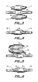
- Figures 3-6 illustrate further embodiments of the invention.
- the substrate 32 comprises pipes or hoses 32 interconnected by a fitting 33
- the article 34 comprises first and second parts 31, 31, each comprising a pre-formed member 4 and gel 10.
- the parts 31 are assembled as shown in Figure 4.
- the tackiness of the gel can be used to keep the parts 31 interconnected, and/or mechanical clamps 36, either integrally formed with the parts 31 or separately attached, can also be used.
- the parts 1 are interconnected on one side by a hinge 35, this embodiment further illustrating the mechanical clamp 36.
- any number of the parts 31 in excess of two can be formed so as to be mutually engagable and provide a complete environmental seal for the complicated structured substrate.
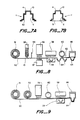
- Figure 7a illustrates another preferred embodiment of the invention.
- an article 11 is formed such that the gel 10 is in intimate contact with the internal surface 6 of the member 4.
- Reference numeral 62 denotes a release sheet disposed onto the gel so as to cover an otherwise exposed surface of the gel.
- the rlease sheet 9 is disposed across the open side of the deformed backing subsequent to its deformation.
- Figure 8 illustrates one preferred process of producing the article of Figure 7, this method being adaptable to continuous production.
- a backing 50 is preferably continuously transported from a roll 51 past a gel dispenser 52 having uncured gel 10 therein, past a doctor blade 54, past a beam 56 for curing and crosslinking the gel to give it desired properties (such as a desired cone penetration, elongation, elasticity, tackiness, etc.), past a thermoforming station 58 which heats the cured gel and backing and forms it into a desired shape 64, past a release sheet dispenser 60 which dispenses a release sheet 62 across an open side of the thermoformed shape 64, and finally to a die cut station 66 which separates the thermoformed shapes 64 which then correspond to the articles 11.
- a gel dispenser 52 having uncured gel 10 therein
- a doctor blade 54 past a beam 56 for curing and crosslinking the gel to give it desired properties (such as a desired cone penetration, elongation, elasticity, tackiness, etc.)
- the beam 56 crosslinks and cures the gel, and further functions to adhere the gel to the backing 50 by crosslinking the gel where it contacts the backing.
- a separate beam 57 can be utilized to crosslink the gel contacting the backing, the separate beam 57 radiating the backing and gel through a surface of the backing opposite the gel.
- the beams 56, 57 can comprise electron beams and/or ultraviolet beams, and the intensity of and dose of radiation is determined to obtain optimum adhesion between the backing and the gel, and to achieve optimum and desired gel properties.
- chemical crosslinking agents can be utilized and mixed with the uncured gel for curing the gel.
- chemical crosslinking agents can be used to also crosslink the gel to the backing and secure it thereto.
- an adhesive can be used to secure the gel to the backing rather than radiation or chemical crosslinking agents.
- a suitable adhesive is a silicone pressure sensitive adhesive.
- FIG 9 Another alternative embodiment is illustrated in Figure 9 wherein a cured gel is applied to the backing rather than an uncured gel as illustrated in Figure 8.
- the cured gel can be applied as part of and embedded within a three dimensional matrix having characteristics as described above with reference to the embodiment of Figure 1, or can be applied as a unitary layer.
- the cured gel can be secured to the backing using adhesives, or radiation as illustrated, as described in the embodiment of Figure 8. If radiation is used, the kind of radiation used and its direction of application (e.g. from the backing side or the gel side) are optional, though it should be understood that the radiation may cause additional crosslinking in the gel, especially if applied from the gel side, and this should be considered in formulating the cured gel which is to be disposed on the backing.
- the thermoforming station 58 heats the cured gel and backing, and subjects the heated gel and backing to a vacuum pressure (which may be augmented by pressure from the above side) within a chamber 59 having a shape corresponding to a final desired shape of the article 11, 64 such that the gel and backing are deformed into the shape of the chamber 59.
- a vacuum pressure which may be augmented by pressure from the above side
- mechanical means can also be utilized to deform the cured gel and backing, numerous kinds and types of deforming pressures and mechanical means being known in the art for thermoforming processes.
- the thermoformed shape 64 thus created is cooled.
- a material of the backing is chosen such that its physical integral strength in its cooled state produces forces tending to maintain this shape which are greater than elastic forces generated by the gel when stretched and deformed by the thermoforming station 58 such that the article remains in the thermoformed shape subsequent to being cooled.
- Typical materials suitable for the backing include high density polyethylene, kynar, polycarbonate, etc.
- the invention is suitable for protecting a wide variety of types of substrates as well as shapes thereof, and is not specifically limited only to bolts, nuts, and pipe fittings, these substrates being described only for illustrative purposes.
- plural parts 31 as described, it can readily be appreciated that a large degree of freedom is possible in utilizing the invention for protecting a vast array of different types of substrates having various shapes, and the number of preformed members having gel disposed thereon can vary and exceed one or two per substrate when the irregular or unique shape of the substrate makes the use of multiple members in excess of two more practicable.
Abstract
Description
- The present invention relates to an article for protecting a substrate from environmental effects such as corrosion, electrical currents, etc.
- Various ways have been proposed in the prior art for protecting a substrate from adverse environmental effects. For example, in the case of nuts and bolts, in very severe environments such as those encountered on ocean-traversing vessels, multiple layers of paint are often disposed on exposed portions of the nuts and bolts for protecting them from corrosion. As an alternative to paint, various types of greases have also been utilized in many circumstances for protecting substrates from adverse environmental contaminants, such as water, and for electrical insulation protection, and also for insulating metal substrates. These methods are disadvantageous in that insufficient corrosion protection is afforded, reentry is difficult, the protection lasts for a relatively short period of time, they are labor intensive, and relatively expensive.
- European Patent Applications Nos. 83306140.1 and 85306157.0 disclose various containers which are substantially filled with gel material, the containers subsequently being disposed in contact with a substrate subsequent to curing the gel. Though these gel filled containers are quite effective in protecting substrates, they are disadvantageous in that they are relatively inefficient since a relatively large amount of gel is required per substrate to be protected.
- Accordingly, it is an object of the invention to eliminate the above-noted drawbacks and to provide an article for protecting a substrate which is relatively inexpensive to produce, is easy to install over the substrate, lasts a relatively long period of time, and can be made easily reenterable, if desired.
- These and other objects are achieved by articles, and methods of producing such articles, the articles including a preshaped member which has an internal surface shape which is similar to an outer surface shape of the substrate to be protected. In one embodiment, an open surface defined by the preshaped member has a flexible gel disposed thereover, the flexible gel comprising a relatively thin layer of gel, such that when the member is disposed over the substrate, the gel is deformed over and around an outer surface of the substrate and is in intimate contact therewith. According to another embodiment of the invention, the thin layer of flexible gel is disposed into intimate contact with substantially the entire inner surface of the preshaped member. With this embodiment, since the internal surface shape of the member is similar to the outer surface shape of the substrate, when the member is disposed over the substrate, again the gel is in intimate contact therewith. Accordingly, both embodiments utilize very small amounts of gel per substrate to be protected. The gel preferably comprises a three-dimensional open cell network, is elastic, has finite elongation, preferably in excess of 200%, and has a cone penetration between 150 and 350 (10⁻¹mm).
- According to a method of the invention for producing the article having the gel disposed into intimate contact with the internal surface of the member, one embodiment of the method comprises continuously disposing a gel onto a backing and subsequently deforming the gel and backing using a vacuum thermoforming process whereby the backing and gel are heated, and deformed such that the gel is stretched upon deformation of the backing, the backing being chosen from a material which has sufficient structural strength upon being cooled to keep the gel in its expanded deformed state and in intimate contact with the backing. Subsequent to deforming the backing, a die station is used to separate the deformed backing having gel thereon, which then comprises an article of the invention.
- According to one preferred embodiment, the gel is disposed onto the backing in a non-cured state, a thickness of the gel is controlled using a doctor blade, the gel is then cured using either chemical means or radiation, the gel is secured to the backing, again using either radiation or chemical means such as an adhesive, and subsequently the cured gel and backing are deformed. According to another preferred embodiment of a method of the invention, a pre-cured gel is disposed on the backing, and the pre-cured gel is secured to the backing using either radiation or chemical means prior to deforming the cured gel and backing.
- Such an article provides an excellent means for protecting irregularly shaped articles using a minimum amount of gel in an efficient manner.
- Figure 1 is a cross-sectional view of a first preferred embodiment of the invention;
- Figure 2 is a full perspective view of the article of Figure 1 disposed in close proximity to a substrate to be protected, and a partial view of an installed article;
- Figures 3-6 illustrate further embodiments of the invention;
- Figures 7a and 7b illustrate further preferred embodiments of articles of the invention; and
- Figures 8-9 illustrate alternative exemplary embodiments for making the articles of Figures 7a and 7b.
- Figure 1 illustrates a cross-sectional view of an article 1 constructed according to a first preferred embodiment of the invention with Figure 2 illustrating, on the left, a perspective view of the article of Figure 1 in close proximity to a
substrate 2 to be protected, and on the right, the article as installed on the substrate. In the embodiment illustrated, thesubstrate 2 is abolt 3 having anut 5 therearound, and the article 1 is generically termed a bolt cover. However, it should be appreciated that thesubstrate 2 can comprise any kind of element which requires some sort of protection from the environment, such as protection from corrosion, protection from electrical discharge, etc., and that the article 1 comprises any member suitable for protecting such a substrate. The invention is most suitable for use with substrates having irregular shapes, though the invention is also suitable for protecting substrates having uniform shapes as well. Though the invention is described with reference to a few exemplary embodiments, in particular a few specific shaped substrates, it should be understood that the invention is applicable to protecting numerous other types and shapes of substrates as well even though the vast majority of substrates in existence which require some kind of protection are not illustrated in the drawings. - The article 1 includes a
preshaped member 4 which has aninternal surface 6 which has a shape similar to an external surface of thesubstrate 2 which is to be protected. In particular, the shapes of thesurfaces member 4 can be shaped so as to form a tight fit about thesubstrate 2 when installed, and it is even possible to form themember 4 so as to be slightly smaller in size than thesubstrate 2 which causes themember 4 to elastically stretch about the substrate when installed providing excellent adhesion. - A protective
flexible gel 10 is disposed across anopen side 12 defined by the shape of thepreshaped member 4, and is secured to thepreshaped member 4 at aperiphery 13 by any appropriate means such as, for example, by an adhesive or by a mechanical clamp. The gel is preferably one of the types described in European Patent Applications Nos. 83306140.1 and 85306157.0. In particular, the gel can comprise a urethane, a silicone, or a nonsilicone liquid rubber with low or no unsaturation which has been crosslinked, with silicone being a preferred embodiment. The gel is a material having an open loop three-dimensional network such that it is elastic and has a finite amount of elongation, and is relatively soft. A preferred embodiment is to use a gel having a cone penetration between 150 and 350 (10⁻¹ mm), and an ultimate elongation of at least 100%, as measured in accordance with American National Standard Designation ASTM-D217 and ASTM-D638, respectively. Preferably, the cone penetration is between 200 and 300 (10⁻¹ mm), and more preferably between 260 and 280 (10⁻¹ mm). Arelease sheet 9 is disposed over thegel 10, the sheet keeping thegel 10 clean and being releasable therefrom prior to installing the article on the substrate. - The ultimate elongation is most preferably in excess of 200%, and most preferably is at least 400%. In addition, as noted, the gel is also elastic such that it tends to resist deformation and generates a restoration force upon being deformed.
- Furthermore, another preferred embodiment is to contain the
gel 10 in a three-dimensional foam network, such as that disclosed in European Patent Application No. 83306140.1. Specifically, the foam network is characterized by a flexible matrix having a plurality of open interstices having an average volume of less than 0.01 inch³, the gel including a plurality of interconnected segments which lie within the interstices of the matrix, the matrix and the gel being such that when they are stretched, the matrix reaches its ultimate elongation before the gel reaches it ultimate elongation. The thickness of the gel and the matrix need not be large, e.g. it can be less than 10 mm, preferably less than 5 mm, and more preferably less than 1 mm. One important function of the matrix is to provide tensile and shear strength for the gel. Accordingly, the matrix, though desirable, is not necessary so long as care is taken in sizing the article such that the ultimate elongation of the gel is not exceeded when the article is placed over the substrate. In the case where the gel is made of a polysiloxane material, a suitable adhesive for securing the gel to the member is a silicone pressure sensitive adhesive. - In operation, the article 1 as described is disposed over the
substrate 2 and placed thereon such that theprotective gel 10 is deformed so as to take on a shape roughly illustrated by the dotted line 14 in Figure 1. One embodiment is to provide a small air escape hole to provide a means for air release fromcavity 23 between themember 4 andgel 10 as thecavity 23 contracts in volume upon installation of the article 1. - It should be understood the
hole 21 is not required. Without thehole 21, air confined within thecavity 23 which contracts upon installation of the article 1 can escape between theperiphery 13 of themember 4 and thegel 10 after which the gel, due to its tackiness, re-adheres and seals to theperiphery 13. With this construction, atmospheric pressure contributes to maintaining themember 4 in its installed position since removal of themember 4 subsequent to installation requires that the volume of thecavity 23 be enlarged which results in a pressure decrease in thecavity 23 whereas pressure outside themember 4 andcavity 23 remains constant thereby creating a pressure differential therebetween. - Even though the elastic deformation of the gel produces a small force tending to push the article off the substrate, several means are available for preventing this from occurring even if the article is subjected to other external, possibly larger forces, e.g., vibrations. First, if the
hole 21 is not provided, as already explained, atmospheric pressure forces would keep the article installed and in place. In addition, the tackiness of the gel also produces a retention force since it is in contact with the substrate and adheres and seals thereto. If thehole 21 is provided, the tackiness of the gel can be made so as to produce sufficient retention forces. In addition, grooves andrecesses 16 forengaging threads 17 can be formed on an inner surface of themember 4. If a substrate not having threads is to be protected, it will be apparent to those skilled in the art that themember 4 may be able to be shaped so as to closely conform in shape to the substrate so as to produce a retention force like that obtained with grooves and recesses which mate with threads, e.g. such as for example grooves and recesses formed on themember 4 which closely conform in shape to similar grooves and recesses on the substrate. Also, themember 4 can be sized so as to form a close fit around at least selected portions of the substrate when installed, and if the material of themember 4 is slightly elastic, it is even possible to size the fit such that the member is caused to stretch around the substrate upon installation which creates relatively large frictional engagement forces therebetween. Any combination of the above is possible when external forces, which may otherwise tend to dislodge the article 1 from the substrate, are anticipated. - Accordingly, it can be appreciated that the article 1 can be made to remain in place and to provide good environmental protection means for the
substrate 2 such that it is protected from adverse environmental contaminants, such as water or other corrosion-producing substances. In addition, if desired, the article 1 is suitable for protectingsubstrates 2 from electrical currents, e.g., the article 1 can have agel 10 which is electrically insulating. - Figures 3-6 illustrate further embodiments of the invention. In Figure 3, the
substrate 32 comprises pipes orhoses 32 interconnected by afitting 33, and thearticle 34 comprises first andsecond parts pre-formed member 4 andgel 10. Theparts 31 are assembled as shown in Figure 4. The tackiness of the gel can be used to keep theparts 31 interconnected, and/ormechanical clamps 36, either integrally formed with theparts 31 or separately attached, can also be used. In Figures 5 and 6, the parts 1 are interconnected on one side by ahinge 35, this embodiment further illustrating themechanical clamp 36. - For more complicated structured substrates, it can be appreciated that any number of the
parts 31 in excess of two can be formed so as to be mutually engagable and provide a complete environmental seal for the complicated structured substrate. - Figure 7a illustrates another preferred embodiment of the invention. In Figure 7a, an article 11 is formed such that the
gel 10 is in intimate contact with theinternal surface 6 of themember 4. This embodiment is advantageous in that any risk of the gel tearing by being stretched upon being installed onto thesubstrate 2 is eliminated since the gel of Figure 7a is not substantially deformed by the installation process.Reference numeral 62 denotes a release sheet disposed onto the gel so as to cover an otherwise exposed surface of the gel. In Figure 7b, therlease sheet 9 is disposed across the open side of the deformed backing subsequent to its deformation. - Figure 8 illustrates one preferred process of producing the article of Figure 7, this method being adaptable to continuous production. According to this process, a
backing 50 is preferably continuously transported from aroll 51 past agel dispenser 52 havinguncured gel 10 therein, past adoctor blade 54, past abeam 56 for curing and crosslinking the gel to give it desired properties (such as a desired cone penetration, elongation, elasticity, tackiness, etc.), past athermoforming station 58 which heats the cured gel and backing and forms it into a desiredshape 64, past arelease sheet dispenser 60 which dispenses arelease sheet 62 across an open side of thethermoformed shape 64, and finally to adie cut station 66 which separates the thermoformed shapes 64 which then correspond to the articles 11. - In this embodiment, the
beam 56 crosslinks and cures the gel, and further functions to adhere the gel to thebacking 50 by crosslinking the gel where it contacts the backing. Alternatively, aseparate beam 57 can be utilized to crosslink the gel contacting the backing, theseparate beam 57 radiating the backing and gel through a surface of the backing opposite the gel. Thebeams - As an alternative to radiation for curing the gel, chemical crosslinking agents can be utilized and mixed with the uncured gel for curing the gel. In addition, if desired, chemical crosslinking agents can be used to also crosslink the gel to the backing and secure it thereto. Alternatively, an adhesive can be used to secure the gel to the backing rather than radiation or chemical crosslinking agents. When the gel comprises a polysiloxane material, a suitable adhesive is a silicone pressure sensitive adhesive.
- Another alternative embodiment is illustrated in Figure 9 wherein a cured gel is applied to the backing rather than an uncured gel as illustrated in Figure 8.
- In the embodiment of Figure 9, the cured gel can be applied as part of and embedded within a three dimensional matrix having characteristics as described above with reference to the embodiment of Figure 1, or can be applied as a unitary layer. According to these additional embodiments, the cured gel can be secured to the backing using adhesives, or radiation as illustrated, as described in the embodiment of Figure 8. If radiation is used, the kind of radiation used and its direction of application (e.g. from the backing side or the gel side) are optional, though it should be understood that the radiation may cause additional crosslinking in the gel, especially if applied from the gel side, and this should be considered in formulating the cured gel which is to be disposed on the backing. In Figure 9, since the gel is precured, a doctor blade is not needed, and this embodiment illustrates radiation grafting of the gel to the backing, though it should be understood that chemical grafting could be used instead. Also, this figure illustrates dispensing the
release sheet 62 onto the exposed surface of the gel subsequent to dispensing the gel but prior to the thermoforming operation, which produces the article of Figure 7a, rather than the article of 7b produced when the release sheet is applied subsequent to theremoforming. - The
thermoforming station 58 heats the cured gel and backing, and subjects the heated gel and backing to a vacuum pressure (which may be augmented by pressure from the above side) within achamber 59 having a shape corresponding to a final desired shape of thearticle 11, 64 such that the gel and backing are deformed into the shape of thechamber 59. In addition to pressure, mechanical means can also be utilized to deform the cured gel and backing, numerous kinds and types of deforming pressures and mechanical means being known in the art for thermoforming processes. Thethermoformed shape 64 thus created is cooled. A material of the backing is chosen such that its physical integral strength in its cooled state produces forces tending to maintain this shape which are greater than elastic forces generated by the gel when stretched and deformed by thethermoforming station 58 such that the article remains in the thermoformed shape subsequent to being cooled. Typical materials suitable for the backing include high density polyethylene, kynar, polycarbonate, etc. - Though the invention has been described with reference to particular preferred embodiments thereof, it should be appreciated that numerous modifications thereto can be made within the level of skill of the ordinary skilled artisan. For example, the invention is suitable for protecting a wide variety of types of substrates as well as shapes thereof, and is not specifically limited only to bolts, nuts, and pipe fittings, these substrates being described only for illustrative purposes. In addition, by utilizing
plural parts 31 as described, it can readily be appreciated that a large degree of freedom is possible in utilizing the invention for protecting a vast array of different types of substrates having various shapes, and the number of preformed members having gel disposed thereon can vary and exceed one or two per substrate when the irregular or unique shape of the substrate makes the use of multiple members in excess of two more practicable. In addition, though several preferred means are described for producing the unique articles of the invention in a continuous manner, it should be appreciated that many variations to the methods described are possible.
Accordingly, the invention is not to be limited by the various specific embodiments described, and is to be limited only by the appended claims.
Claims (20)
- An article for protecting a substrate, comprising:
a first preshaped member having an internal surface shape shaped similar to an outer surface shape of at least part of the substrate to be protected, the member having an open side; and
a thin layer of gel secured to the member for protecting the substrate when the member is disposed over the substrate, the gel being elastic and having a cone penetration between 150 and 350 (10⁻¹mm) and an ultimate elongation in excess of 100%, a volume of the gel being substantially less than a volume enclosed by the internal surface shape and the open side of the member, the gel being cured prior to coming into contact with any part of the substrate. - The article as claimed in Claim 1, the thin layer of gel being secured to the member so as to be disposed across the open side of the member so as to form an open cavity between the gel and the internal surface shape of the member.
- The article as claimed in Claim 1, the thin layer of gel being disposed in contact with at least a major portion of the inner surface shape of the member such that a volume defined by the gel on the internal surface shape and the open side of the member forms an open cavity.
- The article as claimed in Claim 2 or 3, an internal surface shape of the preshaped member being substantially a mirror image of at least part of the outer surface shape of the substrate.
- The article as claimed in Claim 2 or 3, the volume enclosed by the internal surface shape and the open side of the preshaped member being slightly smaller than a volume defined by the at least part of the outer surface shape of the substrate.
- The article as claimed in Claim 2 or 3, the volume enclosed by the internal surface shape and the open side of the preshaped member being substantially the same as a volume defined by at least part of the outer surface shape of the substrate.
- The article as claimed in Claim 1 or 2, further comprising means for securing the gel about a perimeter of the preshaped member, the securing means being an adhesive or a mechanical clamp, the adhesive being a silicone pressure sensitive adhesive.
- The article as claimed in Claim 2 or 3, the member being disposed around the substrate and being sized so as to urge the gel into intimate contact with the substrate to pro-tect the substrate.
- The article as claimed in Claim 2 or 3, the gel comprising a material having a cone penetration between 200 and 300 (10⁻¹ mm), preferably between 260 and 280 (10⁻¹mm), the gel comprising a material having an ultimate elongation in excess of 200%, preferably in excess of 400%, the gel being les than 10 mm thick, preferably less than 1mm.
- The article as claimed in Claim 9, the gel being disposed in a flexible matrix, the flexible matrix preferably comprising a material having a plurality of open interstices having an average volume of less than 0.01 inch³, the gel preferably including a plurality of interconnected segments which lie within the interstices of the matrix, the matrix and the impregnant preferably being such that when the gel and the matrix are stretched, the matrix reaches its ultimate elongation before the gel reaches its ultimate elongation.
- The article as claimed in Claim 10, an outer surface of the gel being tacky, and further comprising a release sheet preferably disposed either across the open side of the member and/or in contact with a substantial portion of an upper surface of the gel.
- The article as claimed in Claim 2 or 3, further comprising means for keeping the member around the substrate.
- The article as claimed in Claim 2 or 3, further comprising a second preshaped member having an internal surface shape shaped similar to another part of the external surface shape of the substrate and having an open side;
a second thin layer of gel, the second layer of gel being disposed either across the open side of the second member or in intimate contact with at least a substantial portion of the internal surface shape of the second member, a volume of the second thin layer of gel being substantially less than a volume enclosed by the internal surface shape and the open side of the second member; and
means for securing the first and second members together. - The article as claimed in Claim 2, the internal surface shape of the member corresponding to a shape of either an outer surface of a bolt and nut or part of a shape of tube-like members interconnected by a fitting.
- The article as claimed in Claim 2 or 3, the member having a hole through an otherwise closed surface thereof for allowing communication between the cavity and an atmosphere.
- The article as claimed in Claim 2 or 3, the member and thin layer of gel together forming a completely closed surface.
- The article as claimed in Claim 3, further comprising means for securing the gel to the inner surface of the member, the securing means preferably comprising an adhesive, and/or crosslinks the adhesive preferably being a silicone pressure sensitive adhesive, the crosslinks being either chemically or radiation produced.
- A method of making an article for protecting a substrate, comprising:
transporting a backing material past a gel dispenser;
dispensing a gel from the gel dispenser onto the backing; and
deforming the backing and the gel into a predetermined shape such that at least a major portion of an inner surface of the backing has gel thereon, the shape being similar to an external surface shape of at least part of a substrate to be protected. - The method as claimed in claim 18, the gel dispenser dispensing a non-cured gel onto the backing, and further comprising the step of curing the dispensed gel prior to deforming the backing.
- The method as claimed in Claim 19, further comprising the step of securing the gel to the backing prior to deforming the backing such that the gel stretches and sticks to the backing when deforming the backing, the backing being continuously transported, the deformed backing being severed from a remainder of the backing subsequent to its deformation, the backing preferably being made from a material selected from the group of materials consisting of high density polyethylene, kynar, and polycarbonate, the gel preferably being tacky subsequent to being cured, and preferably further comprising the step of covering an open side of the deformed backing with a release sheet, the gel preferably being cured by utilizing a chemical agent or radiation, the radiation preferably being beta particles or ultraviolet radiation.
Applications Claiming Priority (4)
| Application Number | Priority Date | Filing Date | Title |
|---|---|---|---|
| US71578985A | 1985-03-25 | 1985-03-25 | |
| US715789 | 1985-03-25 | ||
| US06/730,699 US4643924A (en) | 1985-03-25 | 1985-05-02 | Protective article comprising an elastic gel |
| US730699 | 1985-05-02 |
Related Parent Applications (1)
| Application Number | Title | Priority Date | Filing Date |
|---|---|---|---|
| EP86302209.1 Division | 1986-03-25 |
Publications (1)
| Publication Number | Publication Date |
|---|---|
| EP0443694A1 true EP0443694A1 (en) | 1991-08-28 |
Family
ID=27109417
Family Applications (2)
| Application Number | Title | Priority Date | Filing Date |
|---|---|---|---|
| EP19910200900 Withdrawn EP0443694A1 (en) | 1985-03-25 | 1986-03-25 | Protective article |
| EP19860302209 Expired - Lifetime EP0196219B1 (en) | 1985-03-25 | 1986-03-25 | Protective article |
Family Applications After (1)
| Application Number | Title | Priority Date | Filing Date |
|---|---|---|---|
| EP19860302209 Expired - Lifetime EP0196219B1 (en) | 1985-03-25 | 1986-03-25 | Protective article |
Country Status (11)
| Country | Link |
|---|---|
| US (1) | US4643924A (en) |
| EP (2) | EP0443694A1 (en) |
| JP (1) | JPH0615222B2 (en) |
| AT (1) | ATE78523T1 (en) |
| AU (1) | AU592974B2 (en) |
| BR (1) | BR8601317A (en) |
| CA (1) | CA1275838C (en) |
| DE (1) | DE3686074T2 (en) |
| DK (1) | DK168399B1 (en) |
| NO (1) | NO176188C (en) |
| NZ (1) | NZ215599A (en) |
Cited By (5)
| Publication number | Priority date | Publication date | Assignee | Title |
|---|---|---|---|---|
| JPH0977131A (en) * | 1995-09-13 | 1997-03-25 | Dainippon Printing Co Ltd | Package body and its production |
| EP1058364A1 (en) * | 1999-06-01 | 2000-12-06 | Andrew A.G. | Connector weather-proofing apparatus |
| GB2428436A (en) * | 2005-07-15 | 2007-01-31 | Vetco Gray Controls Ltd | Underwater module with conformal waterproof coating |
| EP1760856A1 (en) * | 2005-08-31 | 2007-03-07 | Belisario Pini | Casing for electric connections and process for manufacturing such a casing |
| WO2014074561A1 (en) * | 2012-11-07 | 2014-05-15 | Dana Automotive Systems Group, Llc | Method for preventing corrosion between two workpieces |
Families Citing this family (76)
| Publication number | Priority date | Publication date | Assignee | Title |
|---|---|---|---|---|
| US5334646B1 (en) * | 1977-03-17 | 1998-09-08 | Applied Elastomerics Inc | Thermoplastic elastomer gelatinous articles |
| US5475890A (en) * | 1977-03-17 | 1995-12-19 | Applied Elastomerics, Inc. | Gelatinous elastomer swabs |
| US5508334A (en) * | 1977-03-17 | 1996-04-16 | Applied Elastomerics, Inc. | Thermoplastic elastomer gelatinous compositions and articles |
| US5037667A (en) * | 1985-05-02 | 1991-08-06 | Raychem Corporation | Radiation grafting of organopolysiloxanes |
| US4950546A (en) * | 1985-05-02 | 1990-08-21 | Raychem Corporation | Radiation grafting of organopolysiloxanes |
| GB8513006D0 (en) * | 1985-05-22 | 1985-06-26 | Raychem Gmbh | Encapsulating electrical components |
| US4741940A (en) * | 1986-05-19 | 1988-05-03 | Raychem Corporation | Articles and methods for protecting substrates |
| US4750962A (en) * | 1987-01-07 | 1988-06-14 | Raychem Corporation | Method of picking up and placing gel material |
| US4889717A (en) * | 1987-04-13 | 1989-12-26 | Raychem Corporation | Barrier material for gel sealant-cable jacket interface |
| WO1988007933A1 (en) * | 1987-04-13 | 1988-10-20 | Raychem Corporation | Barrier material for gel sealant-cable jacket interface |
| CA1319459C (en) * | 1987-12-01 | 1993-06-22 | William David Uken | Environmental sealing |
| JP2799358B2 (en) * | 1988-05-26 | 1998-09-17 | 株式会社シーゲル | Buffer material and method of manufacturing the same |
| US4962286A (en) * | 1988-10-06 | 1990-10-09 | Raychem Corporation | Environmental control, liner for splice enclosure |
| US4982054A (en) * | 1988-10-06 | 1991-01-01 | Raychem Corporation | Telecommunications pedestal closure with environmental control liner |
| US4998894A (en) * | 1988-10-06 | 1991-03-12 | Raychem Corporation | Coaxial cable connector seal |
| US5083940A (en) * | 1988-11-04 | 1992-01-28 | Raychem Corporation | Crossbox protection cap |
| US5273449A (en) * | 1990-03-26 | 1993-12-28 | Raychem Corporation | Modular telecommunications terminal block |
| US6117176A (en) * | 1993-11-15 | 2000-09-12 | Applied Elastomerics, Inc. | Elastic-crystal gel |
| US6333374B1 (en) | 1990-05-21 | 2001-12-25 | Applied Elastomerics, Inc. | Fluffy, strong, solid elastic gels, articles and method of making same |
| US6148830A (en) * | 1994-04-19 | 2000-11-21 | Applied Elastomerics, Inc. | Tear resistant, multiblock copolymer gels and articles |
| US6552109B1 (en) | 1994-04-19 | 2003-04-22 | Applied Elastomerics, Inc. | Gelatinous elastomer compositions and articles |
| US5760117A (en) * | 1990-05-21 | 1998-06-02 | Applied Elastomerics, Inc. | Gelatinous composition and articles |
| US5962572A (en) * | 1994-04-19 | 1999-10-05 | Applied Elastomerics, Inc. | Oriented gel and oriented gel articles |
| US5195125A (en) * | 1990-09-17 | 1993-03-16 | Raychem Corporation | Gel filled RJ11 connector |
| US5376019A (en) * | 1990-09-17 | 1994-12-27 | Raychem Corporation | Gel filled modular electrical connecting block |
| US5246383A (en) * | 1990-09-17 | 1993-09-21 | Raychem Corporation | Gel filled electrical connector |
| IT221753Z2 (en) * | 1991-03-22 | 1994-10-20 | Codrino Giuseppe | CONTINUOUS PROTECTIVE SHEATH, COVERING FOR ELECTRIC WIRING CABLES, PROVIDED, IN CORRESPONDENCE WITH THE GLOBAL HANDLE, THE CONTACT HOLDER BLOCK, OF A STRUCTURAL SEALING ELEMENT |
| EP0577710A1 (en) * | 1991-03-22 | 1994-01-12 | Raychem Corporation | Coaxial cable connector with mandrel spacer and method of preparing coaxial cable |
| JPH06508258A (en) * | 1991-06-07 | 1994-09-14 | レイケム・コーポレイション | Hinged gel-filled safety and environmental protection device |
| US5354210A (en) * | 1991-08-23 | 1994-10-11 | The Whitaker Corporation | Sealant compositions and sealed electrical connectors |
| US5844021A (en) * | 1991-08-23 | 1998-12-01 | The Whitaker Corporation | Sealant compositions and sealed electrical connectors |
| US5360350A (en) * | 1991-08-23 | 1994-11-01 | The Whitaker Corporation | Sealant compositions and sealed electrical connectors |
| US5149281A (en) * | 1991-09-24 | 1992-09-22 | Teltronics, Inc. | Test enabling terminal enclosure apparatus and method |
| US7108873B2 (en) | 1994-04-19 | 2006-09-19 | Applied Elastomerics, Inc. | Gelatinous food elastomer compositions and articles |
| US6420475B1 (en) | 1994-04-19 | 2002-07-16 | Applied Elastomerics, Inc. | Tear resistant elastic crystal gels gel composites and their uses |
| US6324703B1 (en) | 1994-04-19 | 2001-12-04 | Applied Elastomerics, Inc. | Strong, soft, tear resistant insulating compositions and composites for extreme cold weather use |
| US7134236B2 (en) * | 1994-04-19 | 2006-11-14 | Applied Elastomerics, Inc. | Gelatinous elastomer compositions and articles for use as fishing bait |
| US7208184B2 (en) * | 2002-07-20 | 2007-04-24 | Applied Elastomerics, Inc. | Gelatinous food elastomer compositions and articles for use as fishing bait |
| US7193002B2 (en) | 1992-08-24 | 2007-03-20 | Applied Elastomerics, Inc. | Adherent gels, composites, and articles |
| US6627275B1 (en) * | 1994-04-19 | 2003-09-30 | Applied Elastomerics, Incorporated | Tear resistant elastic crystal gels suitable for inflatable restraint cushions and other uses |
| DE69326028T2 (en) * | 1992-09-04 | 2000-03-23 | Raychem Sa Nv | SEAL |
| US5396575A (en) * | 1992-12-18 | 1995-03-07 | Raynet Corporation | Sealed optical fiber closures |
| US6303180B1 (en) | 1993-09-10 | 2001-10-16 | Parker-Hannifin Corporation | Form-in-place EMI gaskets |
| CA2129073C (en) * | 1993-09-10 | 2007-06-05 | John P. Kalinoski | Form-in-place emi gaskets |
| JP2970338B2 (en) * | 1993-09-22 | 1999-11-02 | 住友電装株式会社 | Automatic waterproofing device for wire connection |
| US7234560B2 (en) | 1994-04-19 | 2007-06-26 | Applied Elastomerics, Inc. | Inflatable restraint cushions and other uses |
| US7222380B2 (en) * | 1994-04-19 | 2007-05-29 | Applied Elastomerics, Inc. | Tear resistant gels, composites, and cushion articles |
| US7226484B2 (en) * | 1994-04-19 | 2007-06-05 | Applied Elastomerics, Inc. | Tear resistant gels and articles for every uses |
| US7067583B2 (en) * | 1994-04-19 | 2006-06-27 | Applied Elastomerics, Inc. | Tear resistant adherent gels, composites, and articles |
| US7093599B2 (en) * | 1994-04-19 | 2006-08-22 | Applied Elastomerics, Inc. | Gels, composites, and health care articles |
| US7105607B2 (en) * | 1994-04-19 | 2006-09-12 | Applied Elastomerics, Inc. | Tear resistant gels, composites, and articles |
| US7290367B2 (en) * | 1994-04-19 | 2007-11-06 | Applied Elastomerics, Inc. | Tear resistant gel articles for various uses |
| US6161555A (en) * | 1994-04-19 | 2000-12-19 | Applied Elastomerics, Inc. | Crystal gels useful as dental floss with improved high tear, high tensile, and resistance to high stress rupture properties |
| US7344568B2 (en) | 1994-04-19 | 2008-03-18 | Applied Elastomerics, Inc. | Tear resistant gels, composites, and liner articles |
| US7093316B2 (en) | 1994-04-19 | 2006-08-22 | Applied Elastomerics, Inc. | Gels for force gauging |
| US5525073A (en) * | 1994-06-01 | 1996-06-11 | Raychem Corporation | Environmental protection device with manually operated latch mechanism |
| DE19510341A1 (en) * | 1994-12-24 | 1996-06-27 | Alcatel Kabel Ag | Tension restraint system for electrical lead in plug connector housing |
| US5910524A (en) * | 1995-01-20 | 1999-06-08 | Parker-Hannifin Corporation | Corrosion-resistant, form-in-place EMI shielding gasket |
| US6635354B2 (en) | 1995-01-20 | 2003-10-21 | Parker-Hannifin Corporation | Form-in place EMI gaskets |
| US5641438A (en) * | 1995-01-24 | 1997-06-24 | Bunyan; Michael H. | Method for forming an EMI shielding gasket |
| JP3750875B2 (en) * | 1995-10-27 | 2006-03-01 | 矢崎総業株式会社 | Insulation terminal cover |
| US5727314A (en) * | 1996-02-15 | 1998-03-17 | Erico International Corporation | Method of making an insulated set screw electrical connector |
| US5830136A (en) * | 1996-10-31 | 1998-11-03 | Nellcor Puritan Bennett Incorporated | Gel pad optical sensor |
| US5929138A (en) * | 1996-11-05 | 1999-07-27 | Raychem Corporation | Highly thermally conductive yet highly comformable alumina filled composition and method of making the same |
| US5939672A (en) * | 1997-03-10 | 1999-08-17 | Antronix, Inc. | Hermetically sealed electrical connection to a junction box |
| US6057033A (en) * | 1997-12-12 | 2000-05-02 | Avery Dennison Corporation | Radiation-curable release compositions containing cellulose fibers |
| BR9914850A (en) * | 1998-10-29 | 2001-07-10 | Closure Medical Corp | Combination, processes for making a polymeric container containing a 1,1-disubstituted ethylene monomer, and for storing a 1,1-disubstituted ethylene monomer composition in a container, and, container containing an adhesive monomer composition |
| US6475329B1 (en) | 1999-10-04 | 2002-11-05 | Tyco Electronics Corporation | Primer for silicone compositions |
| US7208192B2 (en) * | 2002-05-31 | 2007-04-24 | Parker-Hannifin Corporation | Thermally or electrically-conductive form-in-place gap filter |
| US6954144B1 (en) | 2003-05-30 | 2005-10-11 | Amco Automated Systems, Inc. | Water pit transmitter assembly |
| US6971897B1 (en) | 2003-10-29 | 2005-12-06 | Tyco Electronics Corporation | Gel-filled telephone jack |
| US20070075504A1 (en) * | 2005-10-03 | 2007-04-05 | Ralf Kurz | Device for delimiting two spaces relative to each other in a liquid-tight or gas-tight fashion |
| CN101793062B (en) * | 2010-02-11 | 2011-07-13 | 中国电力科学研究院 | Ground insulation device suitable for shields |
| US8338710B2 (en) * | 2010-11-03 | 2012-12-25 | Ford Global Technologies, Llc | Short-preventing shield for wire harness terminals |
| US9394442B2 (en) | 2013-03-12 | 2016-07-19 | Commscope Technologies Llc | Hybrid thermoplastic gels and their methods of making |
| US10458455B2 (en) * | 2017-12-22 | 2019-10-29 | The Boeing Company | Systems and methods for making and using a fitted cap for applying a shaped sealant shroud to a portion of a fastener |
Citations (6)
| Publication number | Priority date | Publication date | Assignee | Title |
|---|---|---|---|---|
| US3785899A (en) * | 1971-06-08 | 1974-01-15 | Sealed Air Corp | Method for the manufacture of cellular material for cushioning and other purposes |
| US3985951A (en) * | 1975-07-10 | 1976-10-12 | Niemand Bros. Inc. | Electrical insulator including a polymeric resin foam forming composition and method of insulation |
| US4361457A (en) * | 1973-05-18 | 1982-11-30 | The Klm Company | Method for making a container closure with liner |
| US4425945A (en) * | 1982-09-29 | 1984-01-17 | Mcdonald Ronald T | Thread guard |
| EP0108518A2 (en) * | 1982-10-12 | 1984-05-16 | RAYCHEM CORPORATION (a Delaware corporation) | Apparatus for protection of a substrate |
| US4491225A (en) * | 1983-03-08 | 1985-01-01 | Srp, Inc. | Shock cushioning package |
Family Cites Families (3)
| Publication number | Priority date | Publication date | Assignee | Title |
|---|---|---|---|---|
| US4466843A (en) * | 1981-06-08 | 1984-08-21 | Raychem Corporation | Protection of cable splice |
| US4504699A (en) * | 1982-02-08 | 1985-03-12 | Raychem Pontoise S.A. | Sealable recoverable articles |
| US4431469A (en) * | 1982-09-28 | 1984-02-14 | Niemand Bros. | Electrical connection insulator and method of covering an electrical connection therewith |
-
1985
- 1985-05-02 US US06/730,699 patent/US4643924A/en not_active Expired - Lifetime
-
1986
- 1986-03-24 DK DK135386A patent/DK168399B1/en not_active IP Right Cessation
- 1986-03-24 BR BR8601317A patent/BR8601317A/en unknown
- 1986-03-25 AU AU55237/86A patent/AU592974B2/en not_active Ceased
- 1986-03-25 EP EP19910200900 patent/EP0443694A1/en not_active Withdrawn
- 1986-03-25 NO NO861188A patent/NO176188C/en not_active IP Right Cessation
- 1986-03-25 CA CA 505038 patent/CA1275838C/en not_active Expired - Lifetime
- 1986-03-25 AT AT86302209T patent/ATE78523T1/en not_active IP Right Cessation
- 1986-03-25 NZ NZ21559986A patent/NZ215599A/en unknown
- 1986-03-25 DE DE19863686074 patent/DE3686074T2/en not_active Expired - Fee Related
- 1986-03-25 JP JP6826186A patent/JPH0615222B2/en not_active Expired - Lifetime
- 1986-03-25 EP EP19860302209 patent/EP0196219B1/en not_active Expired - Lifetime
Patent Citations (6)
| Publication number | Priority date | Publication date | Assignee | Title |
|---|---|---|---|---|
| US3785899A (en) * | 1971-06-08 | 1974-01-15 | Sealed Air Corp | Method for the manufacture of cellular material for cushioning and other purposes |
| US4361457A (en) * | 1973-05-18 | 1982-11-30 | The Klm Company | Method for making a container closure with liner |
| US3985951A (en) * | 1975-07-10 | 1976-10-12 | Niemand Bros. Inc. | Electrical insulator including a polymeric resin foam forming composition and method of insulation |
| US4425945A (en) * | 1982-09-29 | 1984-01-17 | Mcdonald Ronald T | Thread guard |
| EP0108518A2 (en) * | 1982-10-12 | 1984-05-16 | RAYCHEM CORPORATION (a Delaware corporation) | Apparatus for protection of a substrate |
| US4491225A (en) * | 1983-03-08 | 1985-01-01 | Srp, Inc. | Shock cushioning package |
Cited By (7)
| Publication number | Priority date | Publication date | Assignee | Title |
|---|---|---|---|---|
| JPH0977131A (en) * | 1995-09-13 | 1997-03-25 | Dainippon Printing Co Ltd | Package body and its production |
| EP1058364A1 (en) * | 1999-06-01 | 2000-12-06 | Andrew A.G. | Connector weather-proofing apparatus |
| GB2428436A (en) * | 2005-07-15 | 2007-01-31 | Vetco Gray Controls Ltd | Underwater module with conformal waterproof coating |
| EP1760856A1 (en) * | 2005-08-31 | 2007-03-07 | Belisario Pini | Casing for electric connections and process for manufacturing such a casing |
| US7563985B2 (en) | 2005-08-31 | 2009-07-21 | Belisario Pini | Gel-filled casing for electric connections |
| CN1933267B (en) * | 2005-08-31 | 2010-05-12 | 贝利萨里奥·皮尼 | Casing for electric connection member filled with dielectric gel |
| WO2014074561A1 (en) * | 2012-11-07 | 2014-05-15 | Dana Automotive Systems Group, Llc | Method for preventing corrosion between two workpieces |
Also Published As
| Publication number | Publication date |
|---|---|
| DK168399B1 (en) | 1994-03-21 |
| AU5523786A (en) | 1986-10-02 |
| DK135386D0 (en) | 1986-03-24 |
| EP0196219B1 (en) | 1992-07-22 |
| NO176188C (en) | 1995-02-15 |
| DK135386A (en) | 1986-09-26 |
| BR8601317A (en) | 1986-12-02 |
| DE3686074T2 (en) | 1993-03-04 |
| ATE78523T1 (en) | 1992-08-15 |
| US4643924A (en) | 1987-02-17 |
| JPS61254331A (en) | 1986-11-12 |
| NO176188B (en) | 1994-11-07 |
| JPH0615222B2 (en) | 1994-03-02 |
| EP0196219A1 (en) | 1986-10-01 |
| DE3686074D1 (en) | 1992-08-27 |
| NO861188L (en) | 1986-09-26 |
| CA1275838C (en) | 1990-11-06 |
| NZ215599A (en) | 1987-07-31 |
| AU592974B2 (en) | 1990-02-01 |
Similar Documents
| Publication | Publication Date | Title |
|---|---|---|
| US4643924A (en) | Protective article comprising an elastic gel | |
| US4690831A (en) | Protective article | |
| JP2540499B2 (en) | Sealing material and its application | |
| AU598336B2 (en) | Article and method for protection of a substrate | |
| US4698115A (en) | Silicone rubber vacuum bag tool and method of fabricating same | |
| CA1223709A (en) | Method and device for sealing | |
| EP1073138A3 (en) | Sealing structure of fuel cell and process for molding rubber packing | |
| US4392898A (en) | Device for enclosing objects | |
| EP0839886A3 (en) | Sheet for protecting paint film | |
| US4466846A (en) | Method of using heat-recoverable articles to produce a pressurizable casing around a substrate | |
| IE821836L (en) | Packaging compressible material | |
| EP0389966A3 (en) | Fluororesin-coated article | |
| CA1298566C (en) | Radiation grafting of organopolysiloxanes | |
| EP0826491A3 (en) | Film with substrate layer containing antiblocking agent | |
| JPH09502077A (en) | Seal material | |
| EP0845409A3 (en) | Method and apparatus for sealing an aircraft penetration | |
| CA2141050A1 (en) | Vehicle window and a process for the preparation thereof | |
| EP0337540A1 (en) | Combination of a support and a semiconductor body and method of manufacturing such a combination | |
| US4750962A (en) | Method of picking up and placing gel material | |
| EP1113490A3 (en) | Resin sealing method for semiconductors and release film used therefor | |
| CA2165195C (en) | Heat shrinkable article | |
| CA2000235A1 (en) | Pedistal telecommunications terminal closure with environmentally controlled liner | |
| US4950546A (en) | Radiation grafting of organopolysiloxanes | |
| CA2065382A1 (en) | Environmental sealing | |
| US5037667A (en) | Radiation grafting of organopolysiloxanes |
Legal Events
| Date | Code | Title | Description |
|---|---|---|---|
| PUAI | Public reference made under article 153(3) epc to a published international application that has entered the european phase |
Free format text: ORIGINAL CODE: 0009012 |
|
| 17P | Request for examination filed |
Effective date: 19910415 |
|
| AC | Divisional application: reference to earlier application |
Ref document number: 196219 Country of ref document: EP |
|
| AK | Designated contracting states |
Kind code of ref document: A1 Designated state(s): AT BE CH DE FR GB IT LI NL SE |
|
| RIN1 | Information on inventor provided before grant (corrected) |
Inventor name: DUBROW, ROBERT D. Inventor name: UKEN, WILLIAM DAVID |
|
| 17Q | First examination report despatched |
Effective date: 19920408 |
|
| STAA | Information on the status of an ep patent application or granted ep patent |
Free format text: STATUS: THE APPLICATION HAS BEEN WITHDRAWN |
|
| 18W | Application withdrawn |
Withdrawal date: 19930121 |