EP0443496A2 - Telemetry apparatus for implantable tissue stimulator - Google Patents
Telemetry apparatus for implantable tissue stimulator Download PDFInfo
- Publication number
- EP0443496A2 EP0443496A2 EP91102289A EP91102289A EP0443496A2 EP 0443496 A2 EP0443496 A2 EP 0443496A2 EP 91102289 A EP91102289 A EP 91102289A EP 91102289 A EP91102289 A EP 91102289A EP 0443496 A2 EP0443496 A2 EP 0443496A2
- Authority
- EP
- European Patent Office
- Prior art keywords
- telemetry
- signal
- digital
- living tissue
- bit
- Prior art date
- Legal status (The legal status is an assumption and is not a legal conclusion. Google has not performed a legal analysis and makes no representation as to the accuracy of the status listed.)
- Ceased
Links
- 230000008878 coupling Effects 0.000 claims abstract description 8
- 238000010168 coupling process Methods 0.000 claims abstract description 8
- 238000005859 coupling reaction Methods 0.000 claims abstract description 8
- 210000001519 tissue Anatomy 0.000 claims description 18
- 238000012544 monitoring process Methods 0.000 claims description 4
- 230000005855 radiation Effects 0.000 claims description 2
- 210000003205 muscle Anatomy 0.000 claims 1
- 230000005540 biological transmission Effects 0.000 abstract description 10
- 238000004804 winding Methods 0.000 description 7
- 238000010586 diagram Methods 0.000 description 6
- 238000001514 detection method Methods 0.000 description 4
- 239000000872 buffer Substances 0.000 description 3
- 210000005241 right ventricle Anatomy 0.000 description 3
- 230000005669 field effect Effects 0.000 description 2
- 230000006870 function Effects 0.000 description 2
- 238000000034 method Methods 0.000 description 2
- 239000003990 capacitor Substances 0.000 description 1
- 230000003750 conditioning effect Effects 0.000 description 1
- 238000012986 modification Methods 0.000 description 1
- 230000004048 modification Effects 0.000 description 1
- 210000004165 myocardium Anatomy 0.000 description 1
- 230000008569 process Effects 0.000 description 1
- 238000011084 recovery Methods 0.000 description 1
- 230000000638 stimulation Effects 0.000 description 1
Images
Classifications
-
- A—HUMAN NECESSITIES
- A61—MEDICAL OR VETERINARY SCIENCE; HYGIENE
- A61N—ELECTROTHERAPY; MAGNETOTHERAPY; RADIATION THERAPY; ULTRASOUND THERAPY
- A61N1/00—Electrotherapy; Circuits therefor
- A61N1/18—Applying electric currents by contact electrodes
- A61N1/32—Applying electric currents by contact electrodes alternating or intermittent currents
- A61N1/36—Applying electric currents by contact electrodes alternating or intermittent currents for stimulation
- A61N1/372—Arrangements in connection with the implantation of stimulators
- A61N1/37211—Means for communicating with stimulators
- A61N1/37252—Details of algorithms or data aspects of communication system, e.g. handshaking, transmitting specific data or segmenting data
- A61N1/3727—Details of algorithms or data aspects of communication system, e.g. handshaking, transmitting specific data or segmenting data characterised by the modulation technique
-
- Y—GENERAL TAGGING OF NEW TECHNOLOGICAL DEVELOPMENTS; GENERAL TAGGING OF CROSS-SECTIONAL TECHNOLOGIES SPANNING OVER SEVERAL SECTIONS OF THE IPC; TECHNICAL SUBJECTS COVERED BY FORMER USPC CROSS-REFERENCE ART COLLECTIONS [XRACs] AND DIGESTS
- Y10—TECHNICAL SUBJECTS COVERED BY FORMER USPC
- Y10S—TECHNICAL SUBJECTS COVERED BY FORMER USPC CROSS-REFERENCE ART COLLECTIONS [XRACs] AND DIGESTS
- Y10S128/00—Surgery
- Y10S128/903—Radio telemetry
Definitions
- This invention relates generally to implantable tissue stimulators such as heart pacemakers and, more particularly, to telemetry apparatus for use in transmitting information from such implantable tissue stimulators.
- Implantable tissue stimulators of this general kind are becoming increasingly sophisticated, and the need has arisen to transmit, within a reasonable amount of time, increased amounts of data from the stimulator to an external receiver.
- a heart pacemaker for example, it is desired to transmit data representing the real time electrocardiogram (ECG) signal from one or more chambers of the heart, both individually and simultaneously, and in addition to transmit other data accumulated over time in an internal memory. Transmitting all of this data requires a high data rate, on the order of at least about 8,000 bits per second.
- Prior telemetry apparatus used in implantable tissue stimulators of this general kind have not been fully adapted to transmit such large amounts of data within a reasonable amount of time. For a multitude of technical reasons, such telemetry apparatus generally have been incapable of transmitting data at the required bit rate.
- the telemetry apparatus includes implantable stimulator means for selectively producing electrical stimulus signals and an electrical lead adapted to carry the stimulus signals to the tissue to be stimulated.
- Telemetry means are mounted with the stimulator means, for producing a telemetry signal and for transmitting the signal to an external receiver.
- the telemetry means includes means for coupling the telemetry signal directly onto the electrical lead, which in turn radiates the signal to the receiver. Utilizing the lead in this fashion facilitates transmission at relatively high frequencies, thus facilitating a high data rate.
- the telemetry means can include digital means for providing a digital telemetry signal along with modulator means for pulse-modulating a carrier signal in accordance with the telemetry signal.
- the pulse-modulated carrier signal is then coupled onto the electrical lead, for radiating to the receiver.
- the apparatus can further include means for monitoring electrical signals generated by the heart and for producing a corresponding analog electrocardiogram (ECG) signal, and the telemetry means can include analog-to-digital converter means for digitizing the ECG signal to produce the digital telemetry signal.
- ECG electrocardiogram
- this digitized ECG signal can be time-division multiplexed with digital data stored in an internal memory device.
- the modulator means provides a single burst of the carrier signal when a bit of the telemetry signal has a first state and provides an absence of the carrier signal when a bit has a second state.
- the burst's duty cycle is preferably less than about 20%, to conserve power.
- the frequency of the carrier signal is preferably in the range of about 10 to 300 megahertz, and the telemetry signal bit rate is preferably at least about 8000 bits per second.
- the tissue stimulator can further include a second electrical lead adapted to carry the stimulus signals to the tissue to be stimulated, and the telemetry means can couple the telemetry signal between the two electrical leads and a metallic case for the implantable means and telemetry means.
- a dipole antenna can thereby be created, for efficiently radiating the telemetry signal to the receiver.
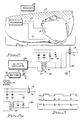
- FIG. 1 is a simplified schematic diagram of a heart pacemaker in accordance with a preferred embodiment of the invention, shown implanted in a body and connected via two electrical leads to the body's heart and also shown with a telemetry receiver located exterior to the body.
- FIG. 2 is a simplified block diagram of a telemetry modulator that is part of the heart pacemaker of FIG. 1.
- FIG. 2(a) is a simplified schematic diagram of alternative circuitry to the circuitry to FIG. 2, for coupling the telemetry signal onto the electrical leads.
- FIG. 3 is a timing diagram depicting several waveforms present in the telemetry modulator of FIG. 2.
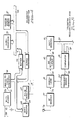
- FIG. 4 is a simplified block diagram of a telemetry transmitter that is included in the heart pacemaker of FIG. 1.
- FIG. 5 is a simplified block diagram of a telemetry receiver/demodulator that is part of the receiver of FIG. 1.
- a heart pacemaker 11 adapted to be implanted into a human body and attached via electrical leads 13 and 15 to the body's heart 17.
- the electrical leads are shown connected to the right auricle 19 and right ventricle 21 of the heart, and they function to carry electrocardiogram (ECG) signals from the heart to the pacemaker, for appropriate analysis, and also to carry stimulus signals from the pacemaker to the heart when a stimulation is determined to be called for.
- ECG electrocardiogram
- the pacemaker 11 is adapted to accumulate data relating to its operation, such as the occurrences of detected irregularities in the ECG signals supplied to it and the occurrences of stimulus signals it produces for transmission over the electrical leads 13 and 15 to the heart 17.
- This data is stored in an internal memory. Periodically, it is desirable to retrieve this stored data from the memory.
- the pacemaker therefore includes a telemetry subsystem, which modulates a carrier signal in accordance with the stored data and transmits the modulated carrier signal outwardly through the patient's skin 23 to an external receiver 25.
- the telemetry signal is used to pulse modulate a 30 megahertz carrier signal, which is then coupled onto one of the electrical leads 13 and 15 for transmission outwardly to the receiver 25.
- the electrical lead as a transmitting antenna enables the pacemaker to transmit significantly more data than was previously possible.
- the modulated carrier signal's frequency is relatively high, the telemetry transmission will not interfere with the pacemaker's ongoing monitoring of the ECG signals it receives on the same lead.
- FIG. 2 depicts a telemetry pulse modulator for modulating the carrier signal with the digital telemetry signal and for coupling the modulated signal onto the electrical lead 15.
- the telemetry signal which has a non-return-to-zero (NRZ) format and a bit rate of about 8,192 hertz, is supplied on line 29 to an encoder 31.
- the encoder converts the NRZ-format signal into a corresponding digital pulse signal, in which each "one" bit of the NRZ signal becomes a short pulse and each "zero" bit of the NRZ signal becomes no pulse at all.
- the NRZ signal and the resulting pulse signal are depicted in FIGS. 3(a) and (b), respectively.
- the pulses of the pulse signal preferably have a duty cycle of about one-eighth.
- the pulse signal is used to switch on and off a field-effect transistor 33, which enables and disables a conventional Colpitts oscillator 35, and thereby produces corresponding bursts having a frequency of about 30 megahertz. These bursts are depicted in FIG. 3(c).
- the 30 megahertz bursts from the Colpitts oscillator 35 are supplied to the input winding 37 of a step-down transformer 39.
- the transformer's low-impedance output winding 41 is connected in series with the electrical lead 15, which thereby functions as an antenna for transmitting the information outwardly to the receiver 25 (FIG. 1).
- the pacemaker's metallic case 43 is connected to signal ground, to provide a return path for the transmitted signal. Data is thereby efficiently transmitted to the receiver.
- Back-to-back diodes 45 and 47 are connected in parallel with the transformer's secondary winding 41, to prevent an excessive voltage from being coupled back to the oscillator 35 if and when the heart 17 (FIG. 1) ever is defibrillated.
- FIG 2(a) An alternative circuit for coupling the modulated carrier signal onto electrical leads 13' and 15' and case 43' is depicted in FIG 2(a).
- the case is connected not to signal ground, but rather to one terminal of the transformer's secondary winding 41'.
- the secondary winding's other terminal is connected to signal ground.
- This alternative circuit configuration is preferred, because it allows both leads to be at the same rf voltage, with improved radiation. A dipole antenna is thereby realized.
- the pacemaker's telemetry subsystem can in one mode be used to transmit outwardly to the receiver 25 data that has been accumulated in an internal memory.
- substantial amounts of data can be transmitted within a very short time duration. This large capacity makes possible the transmission not only of stored data, but also of real-time data representing the digitized ECG signal. Circuitry for formatting and transmitting this data is depicted in FIG. 4.
- two analog ECG signals are received on lines 49 and 51.
- One signal represents the ECG signal from the heart's right auricle 19 and the other represents the ECG signal from the heart's right ventricle 21 (see FIG. 1).
- a multiplexer 55 selects one of the two ECG signals and couples it via line 57 to an analog-to-digital (A/D) converter 59.
- a CMOS switched capacitor A/D converter is preferably used, because it draws very low current and is compatible with the selected bit rate.
- the resulting 8-bit digital word sequence is transmitted in parallel format on a data bus 61 from the A/D converter 59 to an 8-bit shift register 63, which in turn serializes the data for transmission on line 29 to the pulse modulator 27.
- This pulse modulator was described in detail above with reference to FIG. 2. As described above, the pulse modulator provides bursts of the 30 megahertz carrier signal in accordance with the digital data, for transmission from the electrical lead 15 (in the FIG. 2 embodiment) or leads 13 and 15 (in the FIG. 2(a) embodiment) to the external receiver 25.
- 8-bit words are retrieved successively from a random-access memory (RAM) 67 and placed on an 8-bit data bus 69. From there, the successive words are connected via a buffer 71 to the same 8-bit data bus 61 that in the other mode carries the digitized ECG signals and, in turn, through the 8-bit shift register 63 to the pulse modulator 27.
- RAM random-access memory
- Portions of this same telemetry transmitter of FIG. 4 can be used to digitize and store data in the RAM 67 when data is not being telemetered.
- data can be selected by the multiplexer 55 and one or more submultiplexers (not shown), for transmission on line 57 to the A/D converter 59, which in turn produces a succession of corresponding 8-bit words for output on the data bus 61.
- These words are coupled through a buffer 73 onto the data bus 69, for loading into the RAM 67, all under the control of the microprocessor 53.
- this same data that is being stored can be selected for telemetry to the receiver 25, as described above.
- the modulation scheme implemented by the pulse modulator 27 provides a burst of the 30 megahertz carrier signal only when a "one" bit is being transmitted. No signal is transmitted when a "zero" bit is present. Accordingly, to prevent the possibility of no bursts being transmitted for an extended time duration, which could lead to a loss of synchronization in the receiver 25, an 8-bit word of all "zero's" is not allowed. This is not a significant drawback, because 255 8-bit words still remain usable.
- the receiver 25 for receiving, demodulating and detecting the data transmitted from the pacemaker 11 is depicted in FIG. 5. It includes an antenna 75 and rf receiver 77 tuned approximately to the 30 megahertz carrier signal. The rf receiver supplies the received signal on line 79 to a demodulator 81.
- the demodulator preferably has both automatic gain control and automatic frequency control, with the latter being accomplished using an automatically tunable local oscillator. The local oscillator's tuning range must be adequate to track the frequency deviations that might occur in the Colpitts oscillator 35 of the pacemaker's pulse modulator 27.
- a frequency search circuit 83 supplies a saw-tooth waveform on line 85 to the demodulator 81.
- the demodulator uses this saw-tooth waveform to control the frequency of its local oscillator. At some point in the range of the saw-tooth waveform, the demodulator frequency will reach the same frequency as the incoming carrier signal, and the carrier signal will at that time be properly demodulated.
- the demodulator 81 outputs a digital data stream corresponding to that depicted in FIG 3(b) when properly locked onto the received carrier signal.
- This digital signal is transmitted on line 85 to a bit detection circuit 87, which includes a threshold detector having a threshold automatically selected to be approximately one-half of the signal's peak value.
- the bit detection circuit also includes a conventional clock recovery circuit, to facilitate detection of the individual bits.
- the resulting detected data in NRZ form, is then transmitted on line 89 to the data input terminal of a shift register 91, which accumulates each succession of 8-bit words.
- the 8-bit words are output in parallel on a data bus 93, for further processing.
- Synchronization is achieved by continuously monitoring the 8-bits currently being stored in the shift register 91.
- an 8-bit comparator 95 continuously compares the 8-bit words present on the data bus 93 with a stored 8-bit code supplied on lines 97. When the two 8-bit words are in agreement, a lock signal is output on line 99, to terminate further frequency scanning by the demodulator and to inform other subsystems (not shown) in the receiver 25 that synchronization has been reached.
- the present invention provides an improved telemetry system for telemetering substantially increased amounts of data from a heart pacemaker.
- a carrier signal is pulse modulated in accordance with either or both of stored digital data and a digitized electrocardiogram signal, for coupling onto an electrical lead connected directly to the heart. This arrangement facilitates the transmission of substantially higher data rates than previously could be achieved.
Abstract
Description
- This invention relates generally to implantable tissue stimulators such as heart pacemakers and, more particularly, to telemetry apparatus for use in transmitting information from such implantable tissue stimulators.
- Implantable tissue stimulators of this general kind are becoming increasingly sophisticated, and the need has arisen to transmit, within a reasonable amount of time, increased amounts of data from the stimulator to an external receiver. In the case of a heart pacemaker, for example, it is desired to transmit data representing the real time electrocardiogram (ECG) signal from one or more chambers of the heart, both individually and simultaneously, and in addition to transmit other data accumulated over time in an internal memory. Transmitting all of this data requires a high data rate, on the order of at least about 8,000 bits per second.
- Prior telemetry apparatus used in implantable tissue stimulators of this general kind have not been fully adapted to transmit such large amounts of data within a reasonable amount of time. For a multitude of technical reasons, such telemetry apparatus generally have been incapable of transmitting data at the required bit rate.
- It should therefore be appreciated that there is a need for an improved telemetry apparatus and related method for transmitting large quantities of data from an implantable tissue simulator such as a heart pacemaker within a reasonable amount of time. The present invention fulfills this need.
- This invention resides in an improved telemetry apparatus for an implantable tissue stimulator such as a heart pacemaker, which is adapted to transmit large amounts of data within a relatively short time duration. The telemetry apparatus includes implantable stimulator means for selectively producing electrical stimulus signals and an electrical lead adapted to carry the stimulus signals to the tissue to be stimulated. Telemetry means are mounted with the stimulator means, for producing a telemetry signal and for transmitting the signal to an external receiver. In accordance with the invention, the telemetry means includes means for coupling the telemetry signal directly onto the electrical lead, which in turn radiates the signal to the receiver. Utilizing the lead in this fashion facilitates transmission at relatively high frequencies, thus facilitating a high data rate.
- More particularly, the telemetry means can include digital means for providing a digital telemetry signal along with modulator means for pulse-modulating a carrier signal in accordance with the telemetry signal. The pulse-modulated carrier signal is then coupled onto the electrical lead, for radiating to the receiver.
- When the apparatus takes the form of a pacemaker adapted to stimulate a heart muscle, it can further include means for monitoring electrical signals generated by the heart and for producing a corresponding analog electrocardiogram (ECG) signal, and the telemetry means can include analog-to-digital converter means for digitizing the ECG signal to produce the digital telemetry signal. In addition, this digitized ECG signal can be time-division multiplexed with digital data stored in an internal memory device.
- In one suitable modulation scheme, the modulator means provides a single burst of the carrier signal when a bit of the telemetry signal has a first state and provides an absence of the carrier signal when a bit has a second state. The burst's duty cycle is preferably less than about 20%, to conserve power. The frequency of the carrier signal is preferably in the range of about 10 to 300 megahertz, and the telemetry signal bit rate is preferably at least about 8000 bits per second.
- The tissue stimulator can further include a second electrical lead adapted to carry the stimulus signals to the tissue to be stimulated, and the telemetry means can couple the telemetry signal between the two electrical leads and a metallic case for the implantable means and telemetry means. A dipole antenna can thereby be created, for efficiently radiating the telemetry signal to the receiver.
- Other features and advantages of the present invention should become apparent from the following description of the preferred embodiment, taken in conjunction with the accompanying drawings, which illustrate, by way of example, the principles of the invention.
- FIG. 1 is a simplified schematic diagram of a heart pacemaker in accordance with a preferred embodiment of the invention, shown implanted in a body and connected via two electrical leads to the body's heart and also shown with a telemetry receiver located exterior to the body.
- FIG. 2 is a simplified block diagram of a telemetry modulator that is part of the heart pacemaker of FIG. 1.
- FIG. 2(a) is a simplified schematic diagram of alternative circuitry to the circuitry to FIG. 2, for coupling the telemetry signal onto the electrical leads.
- FIG. 3 is a timing diagram depicting several waveforms present in the telemetry modulator of FIG. 2.
- FIG. 4 is a simplified block diagram of a telemetry transmitter that is included in the heart pacemaker of FIG. 1.
- FIG. 5 is a simplified block diagram of a telemetry receiver/demodulator that is part of the receiver of FIG. 1.
- With reference now to the drawings, and particularly to FIG. 1, there is shown a heart pacemaker 11 adapted to be implanted into a human body and attached via
electrical leads heart 17. The electrical leads are shown connected to theright auricle 19 andright ventricle 21 of the heart, and they function to carry electrocardiogram (ECG) signals from the heart to the pacemaker, for appropriate analysis, and also to carry stimulus signals from the pacemaker to the heart when a stimulation is determined to be called for. - The pacemaker 11 is adapted to accumulate data relating to its operation, such as the occurrences of detected irregularities in the ECG signals supplied to it and the occurrences of stimulus signals it produces for transmission over the
electrical leads heart 17. This data is stored in an internal memory. Periodically, it is desirable to retrieve this stored data from the memory. The pacemaker therefore includes a telemetry subsystem, which modulates a carrier signal in accordance with the stored data and transmits the modulated carrier signal outwardly through the patient'sskin 23 to anexternal receiver 25. - In accordance with the invention, the telemetry signal is used to pulse modulate a 30 megahertz carrier signal, which is then coupled onto one of the
electrical leads receiver 25. Using the electrical lead as a transmitting antenna enables the pacemaker to transmit significantly more data than was previously possible. In addition, because of the modulated carrier signal's frequency is relatively high, the telemetry transmission will not interfere with the pacemaker's ongoing monitoring of the ECG signals it receives on the same lead. - FIG. 2 depicts a telemetry pulse modulator for modulating the carrier signal with the digital telemetry signal and for coupling the modulated signal onto the
electrical lead 15. The telemetry signal, which has a non-return-to-zero (NRZ) format and a bit rate of about 8,192 hertz, is supplied online 29 to anencoder 31. The encoder converts the NRZ-format signal into a corresponding digital pulse signal, in which each "one" bit of the NRZ signal becomes a short pulse and each "zero" bit of the NRZ signal becomes no pulse at all. The NRZ signal and the resulting pulse signal are depicted in FIGS. 3(a) and (b), respectively. The pulses of the pulse signal preferably have a duty cycle of about one-eighth. The pulse signal is used to switch on and off a field-effect transistor 33, which enables and disables a conventional Colpitts oscillator 35, and thereby produces corresponding bursts having a frequency of about 30 megahertz. These bursts are depicted in FIG. 3(c). - The 30 megahertz bursts from the Colpitts oscillator 35 are supplied to the input winding 37 of a step-down
transformer 39. The transformer's low-impedance output winding 41 is connected in series with theelectrical lead 15, which thereby functions as an antenna for transmitting the information outwardly to the receiver 25 (FIG. 1). The pacemaker'smetallic case 43 is connected to signal ground, to provide a return path for the transmitted signal. Data is thereby efficiently transmitted to the receiver. Back-to-back diodes secondary winding 41, to prevent an excessive voltage from being coupled back to the oscillator 35 if and when the heart 17 (FIG. 1) ever is defibrillated. - Using the encoding scheme described above sharply reduces the amount of power required to telemeter the stored data. Since bursts of the 30 megahertz carrier signal occur only for "one" bits, and not for "zero" bits, and since each such burst has a duty cycle of only about one-eighth, the oscillator 35 operates on average only about one-sixteenth of the time. When the bursts are not being generated, no power is being consumed. Using this encoding scheme, an average current drain of only 5 to 15 microamps can be achieved.
- An alternative circuit for coupling the modulated carrier signal onto electrical leads 13' and 15' and case 43' is depicted in FIG 2(a). In this alternative circuit, the case is connected not to signal ground, but rather to one terminal of the transformer's secondary winding 41'. The secondary winding's other terminal is connected to signal ground. This alternative circuit configuration is preferred, because it allows both leads to be at the same rf voltage, with improved radiation. A dipole antenna is thereby realized.
- As described above, the pacemaker's telemetry subsystem can in one mode be used to transmit outwardly to the
receiver 25 data that has been accumulated in an internal memory. At the specified bit rate of 8,192 bits per second, substantial amounts of data can be transmitted within a very short time duration. This large capacity makes possible the transmission not only of stored data, but also of real-time data representing the digitized ECG signal. Circuitry for formatting and transmitting this data is depicted in FIG. 4. - In FIG. 4, two analog ECG signals are received on
lines 49 and 51. One signal represents the ECG signal from the heart'sright auricle 19 and the other represents the ECG signal from the heart's right ventricle 21 (see FIG. 1). Under the control of amicroprocessor 53, amultiplexer 55 selects one of the two ECG signals and couples it vialine 57 to an analog-to-digital (A/D)converter 59. A CMOS switched capacitor A/D converter is preferably used, because it draws very low current and is compatible with the selected bit rate. - The resulting 8-bit digital word sequence is transmitted in parallel format on a data bus 61 from the A/
D converter 59 to an 8-bit shift register 63, which in turn serializes the data for transmission online 29 to thepulse modulator 27. This pulse modulator was described in detail above with reference to FIG. 2. As described above, the pulse modulator provides bursts of the 30 megahertz carrier signal in accordance with the digital data, for transmission from the electrical lead 15 (in the FIG. 2 embodiment) or leads 13 and 15 (in the FIG. 2(a) embodiment) to theexternal receiver 25. - Alternatively, when operating in the mode described earlier of transmitting only stored data, 8-bit words are retrieved successively from a random-access memory (RAM) 67 and placed on an 8-
bit data bus 69. From there, the successive words are connected via a buffer 71 to the same 8-bit data bus 61 that in the other mode carries the digitized ECG signals and, in turn, through the 8-bit shift register 63 to thepulse modulator 27. - In an another operating mode, it is desirable to transmit both real-time digitized ECG signals, as well as previously-stored data, in a time-division multiplexed format. This is accomplished, again under the control of the
microprocessor 53, by conditioning themultiplexer 55 to select first one ECG signal then the other for digitizing by the A/D converter 59, after which one 8-bit word is read from theRAM 67. The data are alternatively placed on the data bus 61 for passage through theshift register 63 to thepulse modulator 27. This multiplexing process is repeated for as long as desired. - Portions of this same telemetry transmitter of FIG. 4 can be used to digitize and store data in the
RAM 67 when data is not being telemetered. In particular, such data can be selected by themultiplexer 55 and one or more submultiplexers (not shown), for transmission online 57 to the A/D converter 59, which in turn produces a succession of corresponding 8-bit words for output on the data bus 61. These words are coupled through abuffer 73 onto thedata bus 69, for loading into theRAM 67, all under the control of themicroprocessor 53. Eventually, this same data that is being stored can be selected for telemetry to thereceiver 25, as described above. - As previously discussed, the modulation scheme implemented by the
pulse modulator 27 provides a burst of the 30 megahertz carrier signal only when a "one" bit is being transmitted. No signal is transmitted when a "zero" bit is present. Accordingly, to prevent the possibility of no bursts being transmitted for an extended time duration, which could lead to a loss of synchronization in thereceiver 25, an 8-bit word of all "zero's" is not allowed. This is not a significant drawback, because 255 8-bit words still remain usable. - The
receiver 25 for receiving, demodulating and detecting the data transmitted from the pacemaker 11 is depicted in FIG. 5. It includes anantenna 75 and rfreceiver 77 tuned approximately to the 30 megahertz carrier signal. The rf receiver supplies the received signal on line 79 to ademodulator 81. The demodulator preferably has both automatic gain control and automatic frequency control, with the latter being accomplished using an automatically tunable local oscillator. The local oscillator's tuning range must be adequate to track the frequency deviations that might occur in the Colpitts oscillator 35 of the pacemaker'spulse modulator 27. - To enable the
demodulator 81 to achieve an initial frequency lock with the received carrier signal, afrequency search circuit 83 supplies a saw-tooth waveform online 85 to thedemodulator 81. The demodulator uses this saw-tooth waveform to control the frequency of its local oscillator. At some point in the range of the saw-tooth waveform, the demodulator frequency will reach the same frequency as the incoming carrier signal, and the carrier signal will at that time be properly demodulated. - The
demodulator 81 outputs a digital data stream corresponding to that depicted in FIG 3(b) when properly locked onto the received carrier signal. This digital signal is transmitted online 85 to abit detection circuit 87, which includes a threshold detector having a threshold automatically selected to be approximately one-half of the signal's peak value. The bit detection circuit also includes a conventional clock recovery circuit, to facilitate detection of the individual bits. The resulting detected data, in NRZ form, is then transmitted online 89 to the data input terminal of a shift register 91, which accumulates each succession of 8-bit words. The 8-bit words are output in parallel on adata bus 93, for further processing. - Synchronization is achieved by continuously monitoring the 8-bits currently being stored in the shift register 91. Thus, an 8-
bit comparator 95 continuously compares the 8-bit words present on thedata bus 93 with a stored 8-bit code supplied onlines 97. When the two 8-bit words are in agreement, a lock signal is output online 99, to terminate further frequency scanning by the demodulator and to inform other subsystems (not shown) in thereceiver 25 that synchronization has been reached. - It should be appreciated from the foregoing description that the present invention provides an improved telemetry system for telemetering substantially increased amounts of data from a heart pacemaker. A carrier signal is pulse modulated in accordance with either or both of stored digital data and a digitized electrocardiogram signal, for coupling onto an electrical lead connected directly to the heart. This arrangement facilitates the transmission of substantially higher data rates than previously could be achieved.
- Although the invention has been described in detail with reference only to the presently preferred embodiment, those skilled in the art will appreciate that various modifications can be made without departing from the invention. Accordingly, the invention is only defined only by the following claims.
-
- 11
- heart pacemaker
- 13, 15
- electrical leads
- 17
- heart
- 19
- right auricle of 17
- 21
- right ventricle of 17
- 23
- skin of a patient
- 25
- external receiver
- 27
- pulse modulator
- 29
- line
- 31
- encoder
- 33
- field effect transistor
- 35
- Colpitts oscillator
- 37
- input winding of 39
- 39
- step-down transformer
- 41
- output winding of 39
- 43
- metallic case of 11
- 45, 47
- diodes
- 49, 51
- lines
- 53
- microprocessor
- 55
- multiplexer
- 57
- line
- 59
- analog-to-digital (A/D) converter
- 61
- data bus
- 63
- shift register
- 67
- random access memory
- 69
- data bus
- 71, 73
- buffers
- 75
- antenna
- 77
- rf receiver
- 81
- demodulator
- 83
- frequency search circuit
- 85
- line
- 87
- bit detection circuit
- 89
- line
- 91
- shift register
- 93
- data bus
- 95
- comparator
- 97
- lines
- 99
- line
Claims (7)
- A living tissue stimulator apparatus comprising:
implantable stimulator means for selectively producing electrical stimulus signals;
an electrical lead (15) adapted to carry the stimulus signals from the stimulator means to the tissue (17);
telemetry means mounted with implantable means for producing a telemetry signal and for transmitting it therefrom; and
external receiver means (25) for receiving the telemetry signal transmitted by the telemetry means;
wherein the telemetry means includes means for coupling the telemetry signal onto the electrical lead (15), for radiation outwardly to the receiver means (25). - A living tissue stimulator apparatus as defined in claim 1, wherein:
the apparatus further includes
a metallic case (43) for housing the implantable stimulator means and telemetry means, and
a second electrical lead (13) adapted to carry the stimulus signals from the simulator means to the tissue (17) to be stimulated; and
the telemetry means includes means for applying the telemetry signal between the two electrical leads (13, 15) and the case (43), to provide a dipole antenna. - A living tissue stimulator apparatus as defined in claim 1 or 2, wherein the telemetry means includes:
digital means (59, 63) for providing a digital telemetry signal; and
modulator means (27) for pulse-modulating a carrier signal with the digital telemetry signal, for coupling onto the electrical lead (15) or between the two electrical leads (13, 15) and the case (43). - A living tissue stimulator apparatus as defined in claim 3, wherein:
the digital telemetry signal includes a succession of bits, each having either a first state or a second state; and
the modulator means (27) includes means for providing a single burst of the carrier signal when a bit of the telemetry signal has the first state and an absence of the carrier signal when a bit has the second state. - A living tissue stimulator apparatus as defined in claim 4, wherein:
the single burst of the carrier signal, provided by the modulator means (27) when a bit of the telemetry signal has the first state, has a duty cycle of less than about 0.2; and
the carrier signal modulated by the telemetry means has a frequency in the range of 10 to 300 megahertz. - A living tissue stimulator apparatus as defined in one of the preceding claims, wherein:
the apparatus is a pacemaker (11) adapted to stimulate muscle tissue of a heart (17);
the apparatus further includes means for monitoring electrical signals generated by the heart (17) and for producing a corresponding analog electrocardiogram signal; and
the telemetry means includes analog-to-digital converter means (59) for digitizing the analog electrocardiogram signal to produce a digitized electrocardiogram signal. - A living tissue stimulator apparatus as defined in claim 6, wherein the telemetry means further includes:
memory means (67) for storing digital data; and
multiplexing means (53, 71, 73) for multiplexing the digital data stored by the memory means (62) with the digitized electrocardiogram signal provided by the analog-to-digital converter means (59), to produce the digital telemetry signal.
Applications Claiming Priority (2)
| Application Number | Priority Date | Filing Date | Title |
|---|---|---|---|
| US483162 | 1990-02-20 | ||
| US07/483,162 US5058581A (en) | 1990-02-20 | 1990-02-20 | Telemetry apparatus and method for implantable tissue stimulator |
Publications (2)
| Publication Number | Publication Date |
|---|---|
| EP0443496A2 true EP0443496A2 (en) | 1991-08-28 |
| EP0443496A3 EP0443496A3 (en) | 1992-11-19 |
Family
ID=23918917
Family Applications (1)
| Application Number | Title | Priority Date | Filing Date |
|---|---|---|---|
| EP19910102289 Ceased EP0443496A3 (en) | 1990-02-20 | 1991-02-18 | Telemetry apparatus for implantable tissue stimulator |
Country Status (4)
| Country | Link |
|---|---|
| US (1) | US5058581A (en) |
| EP (1) | EP0443496A3 (en) |
| JP (1) | JP2737885B2 (en) |
| AU (1) | AU629508B2 (en) |
Cited By (5)
| Publication number | Priority date | Publication date | Assignee | Title |
|---|---|---|---|---|
| WO1994001174A2 (en) * | 1992-07-01 | 1994-01-20 | Medtronic, Inc. | Method and apparatus for heart transplant monitoring and analog telemetry calibration |
| WO1996040366A1 (en) * | 1995-06-07 | 1996-12-19 | Intermedics, Inc. | Apparatus and method for the control of an implantable device |
| EP0784996A1 (en) * | 1995-11-28 | 1997-07-23 | Pacesetter AB | Device and method for generating a synthesized ECG |
| US5782890A (en) * | 1992-07-01 | 1998-07-21 | Medtronic, Inc. | Method for heart transplant monitoring and analog telemetry calibration |
| EP1541191A1 (en) * | 2002-08-05 | 2005-06-15 | Japan as represented by president of National Cardiovascular Center | Micro integrated cardiac pacemaker and distributed cardiac pacing system |
Families Citing this family (180)
| Publication number | Priority date | Publication date | Assignee | Title |
|---|---|---|---|---|
| JPH05245215A (en) * | 1992-03-03 | 1993-09-24 | Terumo Corp | Heart pace maker |
| FI97860C (en) * | 1993-11-04 | 1997-03-10 | Polar Electro Oy | Interference-resistant heart rate measurement method |
| US5476488A (en) * | 1993-12-15 | 1995-12-19 | Pacesetter, Inc. | Telemetry system power control for implantable medical devices |
| US5562713A (en) * | 1995-01-18 | 1996-10-08 | Pacesetter, Inc. | Bidirectional telemetry apparatus and method for implantable device |
| US5769876A (en) * | 1996-07-02 | 1998-06-23 | Pacesetter, Inc. | Method and apparatus for telemetering data bidirectionally between two devices, one device incorporating a coarse phase adjustment and the other device incorporating a fine phase adjustment |
| US5861019A (en) * | 1997-07-25 | 1999-01-19 | Medtronic Inc. | Implantable medical device microstrip telemetry antenna |
| US6009350A (en) * | 1998-02-06 | 1999-12-28 | Medtronic, Inc. | Implant device telemetry antenna |
| US6141592A (en) * | 1998-03-06 | 2000-10-31 | Intermedics Inc. | Data transmission using a varying electric field |
| US6201993B1 (en) | 1998-12-09 | 2001-03-13 | Medtronic, Inc. | Medical device telemetry receiver having improved noise discrimination |
| US6223083B1 (en) | 1999-04-16 | 2001-04-24 | Medtronic, Inc. | Receiver employing digital filtering for use with an implantable medical device |
| US6295473B1 (en) | 1999-04-16 | 2001-09-25 | Medtronic, Inc. | Digital delay line receiver for use with an implantable medical device |
| US6240317B1 (en) * | 1999-04-30 | 2001-05-29 | Medtronic, Inc. | Telemetry system for implantable medical devices |
| US6516227B1 (en) | 1999-07-27 | 2003-02-04 | Advanced Bionics Corporation | Rechargeable spinal cord stimulator system |
| US6301504B1 (en) | 1999-10-08 | 2001-10-09 | Pacesetter, Inc. | High speed telemetry system using transmission medium as a component of a telemetry link |
| US6628985B2 (en) | 2000-12-18 | 2003-09-30 | Cardiac Pacemakers, Inc. | Data logging system for implantable medical device |
| US6361522B1 (en) * | 1999-10-21 | 2002-03-26 | Cardiac Pacemakers, Inc. | Drug delivery system for implantable cardiac device |
| US6400990B1 (en) | 2000-02-18 | 2002-06-04 | Pacesetter, Inc. | Patient activated telemetry control unit using bidirectional asymmetric dual-mode telemetry link to communicate with an implanted device |
| US7369890B2 (en) | 2000-11-02 | 2008-05-06 | Cardiac Pacemakers, Inc. | Technique for discriminating between coordinated and uncoordinated cardiac rhythms |
| FR2816828B1 (en) * | 2000-11-23 | 2004-10-22 | Richard Cancel | DEVICE FOR THE REMOTE IMPLEMENTATION AND WITHOUT A MATERIAL LINK OF AN IMPLANT AND IMPLANT IMPLEMENTED BY THIS DEVICE |
| US6574510B2 (en) | 2000-11-30 | 2003-06-03 | Cardiac Pacemakers, Inc. | Telemetry apparatus and method for an implantable medical device |
| US6689117B2 (en) | 2000-12-18 | 2004-02-10 | Cardiac Pacemakers, Inc. | Drug delivery system for implantable medical device |
| US6556871B2 (en) * | 2001-01-04 | 2003-04-29 | Cardiac Pacemakers, Inc. | System and method for receiving telemetry data from an implantable medical device |
| US6622044B2 (en) | 2001-01-04 | 2003-09-16 | Cardiac Pacemakers Inc. | System and method for removing narrowband noise |
| US6708065B2 (en) | 2001-03-02 | 2004-03-16 | Cardiac Pacemakers, Inc. | Antenna for an implantable medical device |
| US7209783B2 (en) * | 2001-06-15 | 2007-04-24 | Cardiac Pacemakers, Inc. | Ablation stent for treating atrial fibrillation |
| US7493162B2 (en) * | 2001-06-15 | 2009-02-17 | Cardiac Pacemakers, Inc. | Pulmonary vein stent for treating atrial fibrillation |
| US7047076B1 (en) | 2001-08-03 | 2006-05-16 | Cardiac Pacemakers, Inc. | Inverted-F antenna configuration for an implantable medical device |
| DE60218708D1 (en) | 2001-09-24 | 2007-04-19 | Cosmetic Technologies Llc | DEVICE AND METHOD FOR INDIVIDUAL COMPOSITION OF COSMETICS |
| US8573263B2 (en) | 2001-09-24 | 2013-11-05 | Cosmetic Technologies, Llc | Apparatus and method for custom cosmetic dispensing |
| US7340303B2 (en) | 2001-09-25 | 2008-03-04 | Cardiac Pacemakers, Inc. | Evoked response sensing for ischemia detection |
| US7225029B2 (en) | 2001-10-26 | 2007-05-29 | Pacesetter, Inc. | Implantable cardiac therapy device with dual chamber can to isolate high-frequency circuitry |
| US6766200B2 (en) | 2001-11-01 | 2004-07-20 | Pacesetter, Inc. | Magnetic coupling antennas for implantable medical devices |
| US6763269B2 (en) | 2001-11-02 | 2004-07-13 | Pacesetter, Inc. | Frequency agile telemetry system for implantable medical device |
| US7039462B2 (en) * | 2002-06-14 | 2006-05-02 | Cardiac Pacemakers, Inc. | Method and apparatus for detecting oscillations in cardiac rhythm |
| US7089055B2 (en) * | 2002-06-28 | 2006-08-08 | Cardiac Pacemakers, Inc. | Method and apparatus for delivering pre-shock defibrillation therapy |
| US7554493B1 (en) * | 2002-07-08 | 2009-06-30 | Boston Scientific Neuromodulation Corporation | Folded monopole antenna for implanted medical device |
| US7103413B2 (en) * | 2002-07-12 | 2006-09-05 | Cardiac Pacemakers, Inc. | Ferrite core telemetry coil for implantable medical device |
| US7072711B2 (en) | 2002-11-12 | 2006-07-04 | Cardiac Pacemakers, Inc. | Implantable device for delivering cardiac drug therapy |
| US7627373B2 (en) | 2002-11-30 | 2009-12-01 | Cardiac Pacemakers, Inc. | Method and apparatus for cell and electrical therapy of living tissue |
| US7065409B2 (en) | 2002-12-13 | 2006-06-20 | Cardiac Pacemakers, Inc. | Device communications of an implantable medical device and an external system |
| US7009511B2 (en) | 2002-12-17 | 2006-03-07 | Cardiac Pacemakers, Inc. | Repeater device for communications with an implantable medical device |
| US7395117B2 (en) | 2002-12-23 | 2008-07-01 | Cardiac Pacemakers, Inc. | Implantable medical device having long-term wireless capabilities |
| US7127300B2 (en) | 2002-12-23 | 2006-10-24 | Cardiac Pacemakers, Inc. | Method and apparatus for enabling data communication between an implantable medical device and a patient management system |
| US20040128161A1 (en) * | 2002-12-27 | 2004-07-01 | Mazar Scott T. | System and method for ad hoc communications with an implantable medical device |
| US6978182B2 (en) | 2002-12-27 | 2005-12-20 | Cardiac Pacemakers, Inc. | Advanced patient management system including interrogator/transceiver unit |
| US7016733B2 (en) * | 2003-04-23 | 2006-03-21 | Medtronic, Inc. | Telemetry antenna for an implantable medical device |
| US7320675B2 (en) | 2003-08-21 | 2008-01-22 | Cardiac Pacemakers, Inc. | Method and apparatus for modulating cellular metabolism during post-ischemia or heart failure |
| US20050113886A1 (en) * | 2003-11-24 | 2005-05-26 | Fischell David R. | Implantable medical system with long range telemetry |
| US7840263B2 (en) | 2004-02-27 | 2010-11-23 | Cardiac Pacemakers, Inc. | Method and apparatus for device controlled gene expression |
| US7764995B2 (en) | 2004-06-07 | 2010-07-27 | Cardiac Pacemakers, Inc. | Method and apparatus to modulate cellular regeneration post myocardial infarct |
| WO2006020189A2 (en) | 2004-07-19 | 2006-02-23 | Barthomolew Julie R | Customized retail point of sale dispensing methods |
| US7567841B2 (en) | 2004-08-20 | 2009-07-28 | Cardiac Pacemakers, Inc. | Method and apparatus for delivering combined electrical and drug therapies |
| US8150509B2 (en) | 2004-10-21 | 2012-04-03 | Cardiac Pacemakers, Inc. | Systems and methods for drug therapy enhancement using expected pharmacodynamic models |
| US8060219B2 (en) | 2004-12-20 | 2011-11-15 | Cardiac Pacemakers, Inc. | Epicardial patch including isolated extracellular matrix with pacing electrodes |
| US7981065B2 (en) | 2004-12-20 | 2011-07-19 | Cardiac Pacemakers, Inc. | Lead electrode incorporating extracellular matrix |
| US8391990B2 (en) | 2005-05-18 | 2013-03-05 | Cardiac Pacemakers, Inc. | Modular antitachyarrhythmia therapy system |
| US7752059B2 (en) | 2005-07-05 | 2010-07-06 | Cardiac Pacemakers, Inc. | Optimization of timing for data collection and analysis in advanced patient management system |
| CN103381284B (en) | 2005-10-14 | 2017-03-01 | 内诺斯蒂姆股份有限公司 | Leadless cardiac pacemaker and system |
| US9168383B2 (en) | 2005-10-14 | 2015-10-27 | Pacesetter, Inc. | Leadless cardiac pacemaker with conducted communication |
| US7616990B2 (en) | 2005-10-24 | 2009-11-10 | Cardiac Pacemakers, Inc. | Implantable and rechargeable neural stimulator |
| US7908014B2 (en) * | 2006-05-05 | 2011-03-15 | Alfred E. Mann Foundation For Scientific Research | Antenna on ceramic case |
| US7720544B2 (en) | 2006-06-09 | 2010-05-18 | Cardiac Pacemakers, Inc. | Systems for enabling telemetry in an implantable medical device |
| US7613522B2 (en) * | 2006-06-09 | 2009-11-03 | Cardiac Pacemakers, Inc. | Multi-antenna for an implantable medical device |
| CA2685251A1 (en) * | 2007-05-04 | 2008-11-13 | Arizona Board Of Regents For And On Behalf Of Arizona State University | Systems and methods for wireless transmission of biopotentials |
| WO2010088687A1 (en) | 2009-02-02 | 2010-08-05 | Nanostim, Inc. | Leadless cardiac pacemaker with secondary fixation capability |
| US9044616B2 (en) | 2010-07-01 | 2015-06-02 | Boston Scientific Neuromodulation Corporation | Charging system for an implantable medical device employing magnetic and electric fields |
| WO2012015954A1 (en) * | 2010-07-27 | 2012-02-02 | Endotronix, Inc. | Transvascular wireless sensor system |
| US9333365B2 (en) * | 2010-07-30 | 2016-05-10 | Medtronic, Inc. | Antenna for an implantable medical device |
| US9610450B2 (en) | 2010-07-30 | 2017-04-04 | Medtronics, Inc. | Antenna for an implantable medical device |
| US9060692B2 (en) | 2010-10-12 | 2015-06-23 | Pacesetter, Inc. | Temperature sensor for a leadless cardiac pacemaker |
| CN103249452A (en) | 2010-10-12 | 2013-08-14 | 内诺斯蒂姆股份有限公司 | Temperature sensor for a leadless cardiac pacemaker |
| US9020611B2 (en) | 2010-10-13 | 2015-04-28 | Pacesetter, Inc. | Leadless cardiac pacemaker with anti-unscrewing feature |
| JP6023720B2 (en) | 2010-12-13 | 2016-11-09 | ナノスティム・インコーポレイテッドNanostim, Inc. | Pacemaker takeout system and takeout method |
| JP2014501136A (en) | 2010-12-13 | 2014-01-20 | ナノスティム・インコーポレイテッド | Delivery catheter system and method |
| JP2014501584A (en) | 2010-12-20 | 2014-01-23 | ナノスティム・インコーポレイテッド | Leadless space maker with radial fixing mechanism |
| AU2012211055B2 (en) | 2011-01-28 | 2017-07-13 | Curonix Llc | Neural stimulator system |
| JP6671843B2 (en) | 2011-04-04 | 2020-03-25 | マイクロン デヴァイシーズ リミテッド ライアビリティ カンパニー | Implantable lead |
| US9220897B2 (en) | 2011-04-04 | 2015-12-29 | Micron Devices Llc | Implantable lead |
| US9240630B2 (en) | 2011-04-29 | 2016-01-19 | Cyberonics, Inc. | Antenna shield for an implantable medical device |
| US9259582B2 (en) | 2011-04-29 | 2016-02-16 | Cyberonics, Inc. | Slot antenna for an implantable device |
| US9265958B2 (en) | 2011-04-29 | 2016-02-23 | Cyberonics, Inc. | Implantable medical device antenna |
| US9089712B2 (en) | 2011-04-29 | 2015-07-28 | Cyberonics, Inc. | Implantable medical device without antenna feedthrough |
| WO2014070316A1 (en) | 2012-09-14 | 2014-05-08 | Endotronix, Inc. | Pressure sensor, anchor, delivery system and method |
| JP2014524279A (en) | 2011-07-29 | 2014-09-22 | スティムウェイブ テクノロジーズ インコーポレイテッド | Remote control of power or polarity selection for neurostimulators |
| EP3912675A1 (en) | 2011-08-12 | 2021-11-24 | Stimwave Technologies Incorporated | Microwave field stimulator |
| EP2755718B8 (en) | 2011-09-15 | 2018-06-06 | Micron Devices LLC | Relay module for implant |
| US9511236B2 (en) | 2011-11-04 | 2016-12-06 | Pacesetter, Inc. | Leadless cardiac pacemaker with integral battery and redundant welds |
| WO2013177006A2 (en) | 2012-05-21 | 2013-11-28 | Stimwave Technologies, Incorporated | Methods and devices for modulating excitable tissue of the exiting spinal nerves |
| WO2014022661A1 (en) | 2012-08-01 | 2014-02-06 | Nanostim, Inc. | Biostimulator circuit with flying cell |
| US8761717B1 (en) | 2012-08-07 | 2014-06-24 | Brian K. Buchheit | Safety feature to disable an electronic device when a wireless implantable medical device (IMD) is proximate |
| EP2938393A1 (en) | 2012-12-26 | 2015-11-04 | Micron Devices, LLC | Wearable antenna assembly |
| ES2661718T3 (en) | 2014-01-10 | 2018-04-03 | Cardiac Pacemakers, Inc. | Methods and systems to improve communication between medical devices |
| EP3092034B1 (en) | 2014-01-10 | 2019-10-30 | Cardiac Pacemakers, Inc. | Systems for detecting cardiac arrhythmias |
| US9409029B2 (en) | 2014-05-12 | 2016-08-09 | Micron Devices Llc | Remote RF power system with low profile transmitting antenna |
| US9694189B2 (en) | 2014-08-06 | 2017-07-04 | Cardiac Pacemakers, Inc. | Method and apparatus for communicating between medical devices |
| US9757570B2 (en) | 2014-08-06 | 2017-09-12 | Cardiac Pacemakers, Inc. | Communications in a medical device system |
| US9808631B2 (en) | 2014-08-06 | 2017-11-07 | Cardiac Pacemakers, Inc. | Communication between a plurality of medical devices using time delays between communication pulses to distinguish between symbols |
| US9526909B2 (en) | 2014-08-28 | 2016-12-27 | Cardiac Pacemakers, Inc. | Medical device with triggered blanking period |
| EP3253449B1 (en) | 2015-02-06 | 2018-12-12 | Cardiac Pacemakers, Inc. | Systems for safe delivery of electrical stimulation therapy |
| EP3827877A1 (en) | 2015-02-06 | 2021-06-02 | Cardiac Pacemakers, Inc. | Systems for treating cardiac arrhythmias |
| US10046167B2 (en) | 2015-02-09 | 2018-08-14 | Cardiac Pacemakers, Inc. | Implantable medical device with radiopaque ID tag |
| WO2016141046A1 (en) | 2015-03-04 | 2016-09-09 | Cardiac Pacemakers, Inc. | Systems and methods for treating cardiac arrhythmias |
| US10050700B2 (en) | 2015-03-18 | 2018-08-14 | Cardiac Pacemakers, Inc. | Communications in a medical device system with temporal optimization |
| WO2016149262A1 (en) | 2015-03-18 | 2016-09-22 | Cardiac Pacemakers, Inc. | Communications in a medical device system with link quality assessment |
| US9808618B2 (en) * | 2015-04-23 | 2017-11-07 | Medtronic, Inc. | Dual chamber intracardiac medical device |
| WO2016172625A1 (en) | 2015-04-23 | 2016-10-27 | Medtronic, Inc. | Intracardiac medical device |
| EP3302169B1 (en) | 2015-06-08 | 2021-07-21 | Cosmetic Technologies, LLC | Automated delivery system of a cosmetic sample |
| US10357159B2 (en) | 2015-08-20 | 2019-07-23 | Cardiac Pacemakers, Inc | Systems and methods for communication between medical devices |
| CN108136186B (en) | 2015-08-20 | 2021-09-17 | 心脏起搏器股份公司 | System and method for communication between medical devices |
| US9968787B2 (en) | 2015-08-27 | 2018-05-15 | Cardiac Pacemakers, Inc. | Spatial configuration of a motion sensor in an implantable medical device |
| US9956414B2 (en) | 2015-08-27 | 2018-05-01 | Cardiac Pacemakers, Inc. | Temporal configuration of a motion sensor in an implantable medical device |
| US10137305B2 (en) | 2015-08-28 | 2018-11-27 | Cardiac Pacemakers, Inc. | Systems and methods for behaviorally responsive signal detection and therapy delivery |
| US10226631B2 (en) | 2015-08-28 | 2019-03-12 | Cardiac Pacemakers, Inc. | Systems and methods for infarct detection |
| US10159842B2 (en) | 2015-08-28 | 2018-12-25 | Cardiac Pacemakers, Inc. | System and method for detecting tamponade |
| WO2017044389A1 (en) | 2015-09-11 | 2017-03-16 | Cardiac Pacemakers, Inc. | Arrhythmia detection and confirmation |
| US10065041B2 (en) | 2015-10-08 | 2018-09-04 | Cardiac Pacemakers, Inc. | Devices and methods for adjusting pacing rates in an implantable medical device |
| US10183170B2 (en) | 2015-12-17 | 2019-01-22 | Cardiac Pacemakers, Inc. | Conducted communication in a medical device system |
| US10905886B2 (en) | 2015-12-28 | 2021-02-02 | Cardiac Pacemakers, Inc. | Implantable medical device for deployment across the atrioventricular septum |
| WO2017127548A1 (en) | 2016-01-19 | 2017-07-27 | Cardiac Pacemakers, Inc. | Devices for wirelessly recharging a rechargeable battery of an implantable medical device |
| US10350423B2 (en) | 2016-02-04 | 2019-07-16 | Cardiac Pacemakers, Inc. | Delivery system with force sensor for leadless cardiac device |
| US10220215B2 (en) | 2016-03-29 | 2019-03-05 | Boston Scientific Neuromodulation Corporation | Far-field short-range radio-frequency antenna on the side of an implantable medical device case |
| CN108883286B (en) | 2016-03-31 | 2021-12-07 | 心脏起搏器股份公司 | Implantable medical device with rechargeable battery |
| US10668294B2 (en) | 2016-05-10 | 2020-06-02 | Cardiac Pacemakers, Inc. | Leadless cardiac pacemaker configured for over the wire delivery |
| US10328272B2 (en) | 2016-05-10 | 2019-06-25 | Cardiac Pacemakers, Inc. | Retrievability for implantable medical devices |
| CN109414582B (en) | 2016-06-27 | 2022-10-28 | 心脏起搏器股份公司 | Cardiac therapy system for resynchronization pacing management using subcutaneous sensing of P-waves |
| WO2018009569A1 (en) | 2016-07-06 | 2018-01-11 | Cardiac Pacemakers, Inc. | Method and system for determining an atrial contraction timing fiducial in a leadless cardiac pacemaker system |
| US10426962B2 (en) | 2016-07-07 | 2019-10-01 | Cardiac Pacemakers, Inc. | Leadless pacemaker using pressure measurements for pacing capture verification |
| US10688304B2 (en) | 2016-07-20 | 2020-06-23 | Cardiac Pacemakers, Inc. | Method and system for utilizing an atrial contraction timing fiducial in a leadless cardiac pacemaker system |
| US10391319B2 (en) | 2016-08-19 | 2019-08-27 | Cardiac Pacemakers, Inc. | Trans septal implantable medical device |
| US10780278B2 (en) | 2016-08-24 | 2020-09-22 | Cardiac Pacemakers, Inc. | Integrated multi-device cardiac resynchronization therapy using P-wave to pace timing |
| US10870008B2 (en) | 2016-08-24 | 2020-12-22 | Cardiac Pacemakers, Inc. | Cardiac resynchronization using fusion promotion for timing management |
| US10758737B2 (en) | 2016-09-21 | 2020-09-01 | Cardiac Pacemakers, Inc. | Using sensor data from an intracardially implanted medical device to influence operation of an extracardially implantable cardioverter |
| EP3515553B1 (en) | 2016-09-21 | 2020-08-26 | Cardiac Pacemakers, Inc. | Leadless stimulation device with a housing that houses internal components of the leadless stimulation device and functions as the battery case and a terminal of an internal battery |
| US10994145B2 (en) | 2016-09-21 | 2021-05-04 | Cardiac Pacemakers, Inc. | Implantable cardiac monitor |
| US10561330B2 (en) | 2016-10-27 | 2020-02-18 | Cardiac Pacemakers, Inc. | Implantable medical device having a sense channel with performance adjustment |
| US10758724B2 (en) | 2016-10-27 | 2020-09-01 | Cardiac Pacemakers, Inc. | Implantable medical device delivery system with integrated sensor |
| WO2018081275A1 (en) | 2016-10-27 | 2018-05-03 | Cardiac Pacemakers, Inc. | Multi-device cardiac resynchronization therapy with timing enhancements |
| JP7038115B2 (en) | 2016-10-27 | 2022-03-17 | カーディアック ペースメイカーズ, インコーポレイテッド | Implantable medical device with pressure sensor |
| WO2018081237A1 (en) | 2016-10-27 | 2018-05-03 | Cardiac Pacemakers, Inc. | Use of a separate device in managing the pace pulse energy of a cardiac pacemaker |
| US10413733B2 (en) | 2016-10-27 | 2019-09-17 | Cardiac Pacemakers, Inc. | Implantable medical device with gyroscope |
| CN109890456B (en) | 2016-10-31 | 2023-06-13 | 心脏起搏器股份公司 | System for activity level pacing |
| WO2018081721A1 (en) | 2016-10-31 | 2018-05-03 | Cardiac Pacemakers, Inc | Systems for activity level pacing |
| WO2018089311A1 (en) | 2016-11-08 | 2018-05-17 | Cardiac Pacemakers, Inc | Implantable medical device for atrial deployment |
| EP3538213B1 (en) | 2016-11-09 | 2023-04-12 | Cardiac Pacemakers, Inc. | Systems and devices for setting cardiac pacing pulse parameters for a cardiac pacing device |
| WO2018093605A1 (en) | 2016-11-21 | 2018-05-24 | Cardiac Pacemakers, Inc. | Leadless cardiac pacemaker providing cardiac resynchronization therapy |
| US11147979B2 (en) | 2016-11-21 | 2021-10-19 | Cardiac Pacemakers, Inc. | Implantable medical device with a magnetically permeable housing and an inductive coil disposed about the housing |
| CN109963618B (en) | 2016-11-21 | 2023-07-04 | 心脏起搏器股份公司 | Leadless cardiac pacemaker with multi-mode communication |
| US10639486B2 (en) | 2016-11-21 | 2020-05-05 | Cardiac Pacemakers, Inc. | Implantable medical device with recharge coil |
| US10881869B2 (en) | 2016-11-21 | 2021-01-05 | Cardiac Pacemakers, Inc. | Wireless re-charge of an implantable medical device |
| US11207532B2 (en) | 2017-01-04 | 2021-12-28 | Cardiac Pacemakers, Inc. | Dynamic sensing updates using postural input in a multiple device cardiac rhythm management system |
| WO2018140623A1 (en) | 2017-01-26 | 2018-08-02 | Cardiac Pacemakers, Inc. | Leadless device with overmolded components |
| EP3573706A1 (en) | 2017-01-26 | 2019-12-04 | Cardiac Pacemakers, Inc. | Intra-body device communication with redundant message transmission |
| US10737102B2 (en) | 2017-01-26 | 2020-08-11 | Cardiac Pacemakers, Inc. | Leadless implantable device with detachable fixation |
| US10905872B2 (en) | 2017-04-03 | 2021-02-02 | Cardiac Pacemakers, Inc. | Implantable medical device with a movable electrode biased toward an extended position |
| AU2018248361B2 (en) | 2017-04-03 | 2020-08-27 | Cardiac Pacemakers, Inc. | Cardiac pacemaker with pacing pulse energy adjustment based on sensed heart rate |
| CA3062861A1 (en) | 2017-04-20 | 2018-10-25 | Endotronix, Inc. | Anchoring system for a catheter delivered device |
| WO2019018644A1 (en) | 2017-07-19 | 2019-01-24 | Endotronix, Inc. | Physiological monitoring system |
| WO2019036600A1 (en) | 2017-08-18 | 2019-02-21 | Cardiac Pacemakers, Inc. | Implantable medical device with pressure sensor |
| US10918875B2 (en) | 2017-08-18 | 2021-02-16 | Cardiac Pacemakers, Inc. | Implantable medical device with a flux concentrator and a receiving coil disposed about the flux concentrator |
| CN111107899B (en) | 2017-09-20 | 2024-04-02 | 心脏起搏器股份公司 | Implantable medical device with multiple modes of operation |
| US11185703B2 (en) | 2017-11-07 | 2021-11-30 | Cardiac Pacemakers, Inc. | Leadless cardiac pacemaker for bundle of his pacing |
| EP3717063B1 (en) | 2017-12-01 | 2023-12-27 | Cardiac Pacemakers, Inc. | Systems for detecting atrial contraction timing fiducials and determining a cardiac interval from a ventricularly implanted leadless cardiac pacemaker |
| EP3717060B1 (en) | 2017-12-01 | 2022-10-05 | Cardiac Pacemakers, Inc. | Leadless cardiac pacemaker with reversionary behavior |
| EP3717059A1 (en) | 2017-12-01 | 2020-10-07 | Cardiac Pacemakers, Inc. | Methods and systems for detecting atrial contraction timing fiducials within a search window from a ventricularly implanted leadless cardiac pacemaker |
| CN111417433A (en) | 2017-12-01 | 2020-07-14 | 心脏起搏器股份公司 | Method and system for detecting atrial contraction timing reference during ventricular filling from a ventricular implanted leadless cardiac pacemaker |
| US11529523B2 (en) | 2018-01-04 | 2022-12-20 | Cardiac Pacemakers, Inc. | Handheld bridge device for providing a communication bridge between an implanted medical device and a smartphone |
| CN111556773A (en) | 2018-01-04 | 2020-08-18 | 心脏起搏器股份公司 | Dual chamber pacing without beat-to-beat communication |
| CN111936046A (en) | 2018-03-23 | 2020-11-13 | 美敦力公司 | VFA cardiac therapy for tachycardia |
| CN111886046A (en) | 2018-03-23 | 2020-11-03 | 美敦力公司 | AV-synchronized VFA cardiac therapy |
| WO2019183512A1 (en) | 2018-03-23 | 2019-09-26 | Medtronic, Inc. | Vfa cardiac resynchronization therapy |
| EP3856331A1 (en) | 2018-09-26 | 2021-08-04 | Medtronic, Inc. | Capture in ventricle-from-atrium cardiac therapy |
| US11951313B2 (en) | 2018-11-17 | 2024-04-09 | Medtronic, Inc. | VFA delivery systems and methods |
| US11679265B2 (en) | 2019-02-14 | 2023-06-20 | Medtronic, Inc. | Lead-in-lead systems and methods for cardiac therapy |
| US11697025B2 (en) | 2019-03-29 | 2023-07-11 | Medtronic, Inc. | Cardiac conduction system capture |
| US11213676B2 (en) | 2019-04-01 | 2022-01-04 | Medtronic, Inc. | Delivery systems for VfA cardiac therapy |
| US11712188B2 (en) | 2019-05-07 | 2023-08-01 | Medtronic, Inc. | Posterior left bundle branch engagement |
| US11305127B2 (en) | 2019-08-26 | 2022-04-19 | Medtronic Inc. | VfA delivery and implant region detection |
| US11813466B2 (en) | 2020-01-27 | 2023-11-14 | Medtronic, Inc. | Atrioventricular nodal stimulation |
| US11911168B2 (en) | 2020-04-03 | 2024-02-27 | Medtronic, Inc. | Cardiac conduction system therapy benefit determination |
| US11813464B2 (en) | 2020-07-31 | 2023-11-14 | Medtronic, Inc. | Cardiac conduction system evaluation |
Citations (3)
| Publication number | Priority date | Publication date | Assignee | Title |
|---|---|---|---|---|
| US4223679A (en) * | 1979-02-28 | 1980-09-23 | Pacesetter Systems, Inc. | Telemetry means for tissue stimulator system |
| US4741340A (en) * | 1985-12-18 | 1988-05-03 | Cordis Corporation | Pulse to sinewave telemetry system |
| US4757816A (en) * | 1987-01-30 | 1988-07-19 | Telectronics, N.V. | Telemetry system for implantable pacer |
Family Cites Families (12)
| Publication number | Priority date | Publication date | Assignee | Title |
|---|---|---|---|---|
| IT1118131B (en) * | 1978-07-20 | 1986-02-24 | Medtronic Inc | IMPROVEMENT IN MULTI-MODE CARDIAC PACEMAKERS ADAPTABLE IMPLANTABLE |
| US4267843A (en) * | 1978-11-06 | 1981-05-19 | Medtronic, Inc. | Means to inhibit a digital cardiac pacemaker |
| US4365290A (en) * | 1979-03-12 | 1982-12-21 | Medtronic, Inc. | Computer system with power control circuit |
| US4281664A (en) * | 1979-05-14 | 1981-08-04 | Medtronic, Inc. | Implantable telemetry transmission system for analog and digital data |
| US4494545A (en) * | 1980-05-27 | 1985-01-22 | Cordis Corporation | Implant telemetry system |
| US4361153A (en) * | 1980-05-27 | 1982-11-30 | Cordis Corporation | Implant telemetry system |
| US4556063A (en) * | 1980-10-07 | 1985-12-03 | Medtronic, Inc. | Telemetry system for a medical device |
| US4453162A (en) * | 1982-05-10 | 1984-06-05 | Telectronics Pty. Ltd. | Efficient and fast-switching telemetry transmitter |
| US4658831A (en) * | 1984-06-18 | 1987-04-21 | Pacific Communications, Inc. | Telemetry system and method for transmission of ECG signals with heart pacer signals and loose lead detection |
| US4681111A (en) * | 1985-04-05 | 1987-07-21 | Siemens-Pacesetter, Inc. | Analog and digital telemetry system for an implantable device |
| US4700707A (en) * | 1985-12-09 | 1987-10-20 | Cordis Corporation | Pulse to sine wave/sample decoder telemetry system |
| US4741341A (en) * | 1986-03-12 | 1988-05-03 | Siemens-Pacesetter, Inc. | Protection circuit and method for implanted ECG telemetry circuits |
-
1990
- 1990-02-20 US US07/483,162 patent/US5058581A/en not_active Expired - Lifetime
-
1991
- 1991-02-12 AU AU70991/91A patent/AU629508B2/en not_active Ceased
- 1991-02-18 EP EP19910102289 patent/EP0443496A3/en not_active Ceased
- 1991-02-19 JP JP3047725A patent/JP2737885B2/en not_active Expired - Lifetime
Patent Citations (3)
| Publication number | Priority date | Publication date | Assignee | Title |
|---|---|---|---|---|
| US4223679A (en) * | 1979-02-28 | 1980-09-23 | Pacesetter Systems, Inc. | Telemetry means for tissue stimulator system |
| US4741340A (en) * | 1985-12-18 | 1988-05-03 | Cordis Corporation | Pulse to sinewave telemetry system |
| US4757816A (en) * | 1987-01-30 | 1988-07-19 | Telectronics, N.V. | Telemetry system for implantable pacer |
Cited By (10)
| Publication number | Priority date | Publication date | Assignee | Title |
|---|---|---|---|---|
| WO1994001174A2 (en) * | 1992-07-01 | 1994-01-20 | Medtronic, Inc. | Method and apparatus for heart transplant monitoring and analog telemetry calibration |
| WO1994001174A3 (en) * | 1992-07-01 | 1994-06-09 | Medtronic Inc | Method and apparatus for heart transplant monitoring and analog telemetry calibration |
| US5402794A (en) * | 1992-07-01 | 1995-04-04 | Medtronic, Inc. | Method and apparatus for heart transplant monitoring and analog telemetry calibration |
| US5782890A (en) * | 1992-07-01 | 1998-07-21 | Medtronic, Inc. | Method for heart transplant monitoring and analog telemetry calibration |
| WO1996040366A1 (en) * | 1995-06-07 | 1996-12-19 | Intermedics, Inc. | Apparatus and method for the control of an implantable device |
| EP0784996A1 (en) * | 1995-11-28 | 1997-07-23 | Pacesetter AB | Device and method for generating a synthesized ECG |
| US5740811A (en) * | 1995-11-28 | 1998-04-21 | Pacesetter Ab | Device and method for generating a synthesized ECG |
| EP1541191A1 (en) * | 2002-08-05 | 2005-06-15 | Japan as represented by president of National Cardiovascular Center | Micro integrated cardiac pacemaker and distributed cardiac pacing system |
| EP1541191A4 (en) * | 2002-08-05 | 2007-09-05 | Japan Government | Micro integrated cardiac pacemaker and distributed cardiac pacing system |
| EP2047887A1 (en) * | 2002-08-05 | 2009-04-15 | Japan as represented by president of National Cardiovascular Center | Distributed cardiac pacing system |
Also Published As
| Publication number | Publication date |
|---|---|
| US5058581A (en) | 1991-10-22 |
| AU629508B2 (en) | 1992-10-01 |
| AU7099191A (en) | 1991-08-22 |
| JPH04218171A (en) | 1992-08-07 |
| EP0443496A3 (en) | 1992-11-19 |
| JP2737885B2 (en) | 1998-04-08 |
Similar Documents
| Publication | Publication Date | Title |
|---|---|---|
| US5058581A (en) | Telemetry apparatus and method for implantable tissue stimulator | |
| US5383912A (en) | Apparatus for high speed data communication between an external medical device and an implantable medical device | |
| US5127404A (en) | Telemetry format for implanted medical device | |
| US5016634A (en) | Implantable medical device with means for telemetric transmission of data | |
| US5766232A (en) | Method and apparatus for altering the Q of an implantable medical device telemetry antenna | |
| US6889086B2 (en) | Passive telemetry system for implantable medical device | |
| US4556063A (en) | Telemetry system for a medical device | |
| US7392090B2 (en) | Data logging system for implantable medical device | |
| US5814089A (en) | Leadless multisite implantable stimulus and diagnostic system | |
| US7218967B2 (en) | System and method for real-time remote monitoring of implantable medical devices | |
| US4539992A (en) | Method and apparatus for communicating with implanted body function stimulator | |
| US6223083B1 (en) | Receiver employing digital filtering for use with an implantable medical device | |
| US5562713A (en) | Bidirectional telemetry apparatus and method for implantable device | |
| US6456887B1 (en) | Low energy consumption RF telemetry control for an implantable medical device | |
| CA1072185A (en) | Apparatus for sensing and transmitting a pacemaker's stimulating pulse | |
| EP0001915B1 (en) | Hearing prosthesis | |
| US4459989A (en) | Non-invasive multiprogrammable tissue stimulator and methods for use | |
| EP0216903A1 (en) | Telemetry system for an implantable device | |
| US6370433B1 (en) | Interrogation of an implantable medical device using broadcast audible sound communication | |
| WO2019108742A1 (en) | Device and method to reduce artifact from tissue conduction communication transmission | |
| US4220156A (en) | Low power implantable apparatus and method for receiving an AM signal | |
| EP0001708A2 (en) | Heart pacemaker and monitor | |
| EP3669935A1 (en) | Capacitor-discharge communication scheme for an implantable medical system | |
| JPH0344785B2 (en) | ||
| CA2047367A1 (en) | Low power a/d converter for an implantable medical device |
Legal Events
| Date | Code | Title | Description |
|---|---|---|---|
| PUAI | Public reference made under article 153(3) epc to a published international application that has entered the european phase |
Free format text: ORIGINAL CODE: 0009012 |
|
| AK | Designated contracting states |
Kind code of ref document: A2 Designated state(s): DE FR GB IT NL SE |
|
| PUAL | Search report despatched |
Free format text: ORIGINAL CODE: 0009013 |
|
| AK | Designated contracting states |
Kind code of ref document: A3 Designated state(s): DE FR GB IT NL SE |
|
| 17P | Request for examination filed |
Effective date: 19921216 |
|
| RAP1 | Party data changed (applicant data changed or rights of an application transferred) |
Owner name: PACESETTER AB |
|
| 17Q | First examination report despatched |
Effective date: 19950201 |
|
| RAP1 | Party data changed (applicant data changed or rights of an application transferred) |
Owner name: PACESETTER, INC. |
|
| STAA | Information on the status of an ep patent application or granted ep patent |
Free format text: STATUS: THE APPLICATION HAS BEEN REFUSED |
|
| 18R | Application refused |
Effective date: 19951225 |