EP0442642B1 - Multi unit electrical apparatus with forced air cooling - Google Patents
Multi unit electrical apparatus with forced air cooling Download PDFInfo
- Publication number
- EP0442642B1 EP0442642B1 EP91300882A EP91300882A EP0442642B1 EP 0442642 B1 EP0442642 B1 EP 0442642B1 EP 91300882 A EP91300882 A EP 91300882A EP 91300882 A EP91300882 A EP 91300882A EP 0442642 B1 EP0442642 B1 EP 0442642B1
- Authority
- EP
- European Patent Office
- Prior art keywords
- fan
- housing
- fans
- receiving means
- impedance
- Prior art date
- Legal status (The legal status is an assumption and is not a legal conclusion. Google has not performed a legal analysis and makes no representation as to the accuracy of the status listed.)
- Expired - Lifetime
Links
Images


Classifications
-
- G—PHYSICS
- G11—INFORMATION STORAGE
- G11B—INFORMATION STORAGE BASED ON RELATIVE MOVEMENT BETWEEN RECORD CARRIER AND TRANSDUCER
- G11B33/00—Constructional parts, details or accessories not provided for in the other groups of this subclass
- G11B33/12—Disposition of constructional parts in the apparatus, e.g. of power supply, of modules
- G11B33/125—Disposition of constructional parts in the apparatus, e.g. of power supply, of modules the apparatus comprising a plurality of recording/reproducing devices, e.g. modular arrangements, arrays of disc drives
- G11B33/127—Mounting arrangements of constructional parts onto a chassis
- G11B33/128—Mounting arrangements of constructional parts onto a chassis of the plurality of recording/reproducing devices, e.g. disk drives, onto a chassis
-
- G—PHYSICS
- G06—COMPUTING; CALCULATING OR COUNTING
- G06F—ELECTRIC DIGITAL DATA PROCESSING
- G06F1/00—Details not covered by groups G06F3/00 - G06F13/00 and G06F21/00
- G06F1/16—Constructional details or arrangements
- G06F1/20—Cooling means
-
- G—PHYSICS
- G11—INFORMATION STORAGE
- G11B—INFORMATION STORAGE BASED ON RELATIVE MOVEMENT BETWEEN RECORD CARRIER AND TRANSDUCER
- G11B33/00—Constructional parts, details or accessories not provided for in the other groups of this subclass
- G11B33/14—Reducing influence of physical parameters, e.g. temperature change, moisture, dust
- G11B33/1406—Reducing the influence of the temperature
- G11B33/1413—Reducing the influence of the temperature by fluid cooling
- G11B33/142—Reducing the influence of the temperature by fluid cooling by air cooling
-
- H—ELECTRICITY
- H05—ELECTRIC TECHNIQUES NOT OTHERWISE PROVIDED FOR
- H05K—PRINTED CIRCUITS; CASINGS OR CONSTRUCTIONAL DETAILS OF ELECTRIC APPARATUS; MANUFACTURE OF ASSEMBLAGES OF ELECTRICAL COMPONENTS
- H05K7/00—Constructional details common to different types of electric apparatus
- H05K7/20—Modifications to facilitate cooling, ventilating, or heating
- H05K7/20709—Modifications to facilitate cooling, ventilating, or heating for server racks or cabinets; for data centers, e.g. 19-inch computer racks
- H05K7/20718—Forced ventilation of a gaseous coolant
Definitions
- This invention relates to multi unit electrical apparatus with forced air cooling.
- Multi unit electrical systems are commonly employed to allow the user to tailor a system to his own requirements.
- a typical application of such a multi unit system is in the field of mass data storage.
- a plurality of data storage devices such as magnetic disk drives, are mounted in a box which also incorporates cooling fans and a power supply.
- the data storage devices may be used together to provide higher reliability by, for example, allowing duplication of information, or else to increase storage capacity. If the storage devices are removable this has the added advantage of allowing the user to remove and replace defective devices, or to lock away devices containing especially sensitive information.
- enclosing one or more devices and power supply within a single box imposes restrictions on the ability to maintain the devices and power supply within safe operating temperatures. Thus forced air cooling will usually be necessary.
- a second example is described in European Patent Application number 328 260, in which two customer removable data storage units in canisters are mounted in the front of a drawer.
- a power supply is located at the rear of the drawer separated from the devices by an internal bulkhead in which are located two axial fans for providing forced air cooling. While different device types may be mounted inside a common canister, no provision for devices having different cooling requirements is described in the application.
- European Patent Application number 320 720 describes a computer cooling system using two centrifugal fans, both of which normally operate at reduced capacity. A control system automatically detects the failure of one fan and increases the speed of the other, to maintain a substantially constant flow of cooling air through the computer.
- UK patent application number 8916214.3 (UK9-89-022) and a related article "The Design and Development of a Low Noise DC Motor Driven Centrifugal Fan” (D.S. Gaunt and R.K. Russell, Internoise conference proceedings, December 1989, pp 151-156) describe a particularly quiet motor and fan arrangement for use in low noise level applications.
- a direct current brushless electric motor is used to drive a dual entry centrifugal fan, the scroll of which is shaped to reduce noise to a minimum.
- This motor/fan arrangement also has the property that the motor rpm tends to decrease with decreasing fan back pressure.
- the user can choose the type and number of devices, and therefore the number and position of different devices can vary within a unit.
- the unit airflow characteristics will also vary. This can result in uneven cooling of the devices and the power supply to the rear of the devices.
- Each device may be provided with its own dedicated fan which may be tunable in terms of speed and air flow rate to the cooling requirements of its device. This however would be an expensive and time consuming operation and would tend to dictate against the use of such a cooling system where device interchangeability is required.
- the invention provides electrical apparatus including: a housing including a plenum extending substantially across the width of the housing and a receiving means located at one side thereof, said receiving means comprising a plurality of bays separated by dividing walls, each bay extending from one end of said housing to said plenum and being adapted to receive one of a plurality of interchangeable electrical units; fan means mounted within the housing behind the receiving means and drawing air from said plenum for producing an air flow through the housing past such electrical units, the fan means comprising a dual side entry open loop brushless direct current centrifugal fan positioned such that each fan entry is opposite one of said bays; and a power supply also mounted within said housing and located in the air flow path through the housing.
- the power supply and the receiving means are located on opposite sides of the fan means.
- the receiving means are substantially coextensive with one end of the housing.
- a pair of dual side entry fans are axially spaced across the width of the housing such that each side aperture is in line with a bay, each fan being thus associated with two bays.
- the use of one or more open loop dc centrifugal fans in a housing having this geometrical configuration provides an efficient and versatile method of cooling the units and power supply.
- the speed of an open loop centrifugal brushless dc fan (distinct from the fan described in EP 320 720) varies with back pressure and because the fans are located adjacent to the receiving means, as the impedance presented by the unit or units in the receiving means decreases, then so does the back pressure. This results in a decrease in fan speed and hence of fan noise.
- Apparatus with this type of housing and cooling arrangement would find use in a variety of different environments. In one configuration all the units are of the same type, for example magnetic disk drives.
- Interchangeable units provide one mechanism whereby the fan input impedance may vary; another example of such a mechanism is seen in an apparatus having flexible cabling, such as ribbon cabling, passing near to the fan inlet.
- a cable may partially or wholly block a fan inlet, thereby increasing the fan back pressure.
- the fan would speed up, helping to maintain the overall flow of cooling air.
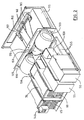
- figure 1 shows an exploded isometric view of a data storage system.
- This system is an example of an electrical apparatus according to the present invention.
- the component parts of the data storage system 10 are mounted on a chassis 20.
- the chassis 20 comprises a drawer which fits into a standard 19-inch (483 mm) wide rack, and which, in operation, is covered by a permanently mounted lid 25.
- the system includes a power switch and indicator lamp 140 fixed at the front left side of the drawer.
- the chassis 20 may be considered as three sections 35, 40, and 45.
- Data storage devices 50, 55, 60 and 65 are located in section 35.
- two tape drives 50 and 55, and two magnetic disk drives 60 and 65 are shown.
- the devices may comprise any combination of devices such as magnetic tape drives, magnetic disk drives, or optical disk drives.
- Each of the data storage devices is located in a device bay 80 defined by a divider 70 and is held in place by mounting rails 75. In this embodiment the devices are hard-wired into the storage system. However, low insertion force plugs and sockets could be used to provide electrical connections to the devices. Because each device is of a standard size (5.25 inch form factor), it would theoretically be possible to put a device into any one of the bays 80.
- the diagram shows storage devices corresponding to each of the device bays 80, it is possible to configure the data storage system 10 such that one or more of the device bays does not contain a storage device.
- an empty bay would be substantially blanked off using a shutter, to prevent an imbalance in the cooling air flow.
- a front panel 30 having apertures 135 is mounted on chassis 20. If the user does not require access to the front of the devices (the case with hard disk drives), grills 85 may be mounted on front panel 30 covering apertures 135, to allow cooling air to enter the drawer and to improve the appearance of the data storage system. The air flow past a device which presents a particularly high air flow impedance may be improved by opening slots 137 in panel 30.
- Section 40 of the chassis 20 houses the cooling fans and also much of the cabling associated with the storage devices.
- two dual entry centrifugal fans 100 driven by open loop brushless direct current (“BLDC") motors are used to force cooling air through the storage system 10.
- the fans 100 are of the type described in UK Patent Application number 8916214.3; one such fan is shown in figure 4.
- the fans 100 are mounted on mounting plate 105 which is then attached to frame 110.
- the fans 100 are arranged to draw cooling air through the grills 85 or slots 137 on front panel 30, and over the storage devices located in bays 80, into a plenum.
- the air From the plenum, the air enters the dual inlets of fans 100, and is then forced through vents in the mounting plate 105 into section 45 of chassis 20 which houses the power supply unit 115.
- the cooling air finally exhausts through outlet vents 120 in backplate 125, and also through vents (not shown) in the power supply unit 115.
- Figure 2 is another isometric view of the data storage system.
- the layout of the cables carrying signals to and from data storage devices 50,55,60 and 65 is shown. For clarity, certain other parts are omitted from figure 2.
- Two sets of cables are used in the data storage system; flat, multiconductor ribbon cables 150 are used to carry data and control information to and from the data storage devices, and smaller cables 155 are used to carry power to the devices.
- Data is passed to and from the data storage system via external multiway connectors 165. These connectors are mounted on a sub assembly 157 and are electrically connected to corresponding internal multiway connectors 160.
- the cables 150 are attached to connectors 160 and pass over the power supply unit 115 into slot 170.
- Slot 170 includes a flap mechanism to prevent the flow of air through the slot.
- the cables emerge from slot 170 and pass between the fans 100 to reach the data storage devices. Apart from the fan outlets this slot is the only aperture in the mounting plate 105 which thus acts as a bulkhead against leakage of air around the fans.
- a "daisy-chain" system of cabling is used.
- a single, continuous cable starts at one of the internal connectors 160, connects to each of the data storage devices in turn, and then returns to the other one of the internal connectors 160.
- FIG. 3 shows a plan view of the data storage system, with the lid 25 removed for clarity. Again, the path of the ribbon cable 150 is shown.
- FIGS. 2 and 3 are drawn to show a very tidy cable arrangement, it should be noted that, in the present embodiment, the cables are not constrained to lie in the paths shown.
- the chassis 20 has a tubular construction; this means that when the data storage system is assembled the cable 150 must be long enough that connections can be made to the storage devices with the devices removed from the chassis. When the devices are subsequently positioned in bays 80, the cable is pushed back into the chassis, so that it is loosely bunched in section 40. Because of this bunching, it is possible that a portion of the cable may partially block one of the fan entries.
- FIG 4 is an exploded view of one of the fans 100.
- the fan is driven by a brushless direct current motor; in the figure this is hidden by the motor control printed circuit board 180.
- the motor drives an impeller 182, comprising fan blades 183 and 184.
- the fan is assembled into a scroll 186 having side walls 188.
- the rectangular output aperture 190 is surrounded by out-turned mounting flanges 192.
- the motor/impeller assembly is held in place by the annular outer plate 194. In operation, air is taken into the fan through the aperture in each end plate 194, and is exhausted through the outlet 190.
- Figure 5 shows a graph of pressure difference in mm of water (axis 200) against air flow in litres per second (axis 210).
- two BLDC centrifugal fans are used to provide forced air cooling of the data storage system.
- the performance of constant speed axial fans in an otherwise similar storage system will also be discussed below, for comparison purposes.
- curves 220, 230 and 235 represent typical fan performances (in this case the pressure difference on axis 200 is the fan back pressure), while curves 240 and 250 show the relationship between the pressure difference across an impedance and air flow through that impedance, for systems having two different impedances.
- This quadratic equation is plotted as curves 240 and 250, showing this relationship for a high and a low impedance respectively.
- the high impedance curve 240 corresponds to a data storage system having three tape drives and one blanking shutter mounted in bays 80.
- the low impedance curve 250 corresponds to a storage system having four disk drives.
- Curves 220, 230 and 235 show the performance of typical cooling fans.
- the curves show the fan back pressure plotted against the air flow through the fan for typical constant speed axial fans (curves 230 and 235) and a BLDC centrifugal fan as described above (curve 220). Both types of fan have the property that the air flow increases as the fan back pressure decreases.
- the rotational speed of the axial fan is constant over the range of back pressures shown, the rotational speed of the BLDC centrifugal fan tends to decrease as the fan back pressure decreases.
- the storage devices each require a certain minimum flow of cooling air for reliable operation.
- the same fans can be installed for each possible configuration of storage devices. Therefore the fans 100 are selected in order that this minimum flow is provided under the "worst case" conditions. In fact two sets of worst case conditions are considered. The first is when the combination of data storage devices presenting the highest impedance to the flow of cooling air is installed in bays 80 (the "highest impedance” combination), and the second occurs when the combination of devices requiring the highest flow of cooling air (the "highest flow” combination) is installed.
- the highest impedance combination of devices is considered to be that of three tape drives and one blanking shutter. In this case a minimum of 18.3 litres per second ("l/s") of cooling air must flow through the system. The highest total flow (22.7 l/s) is required by a system comprising four disk drives.
- a fan is selected such that its performance curve (220 or 230) crosses the impedance curve 240 (which corresponds to the highest impedance combination of devices) at an intersection 300 corresponding to an air flow on axis 210 of at least 18.3 l/s.
- the two fan performance curves shown in figure 5 which pass through point 300 relate to particular fans capable of providing at least 18.3 litres of air per second through the system under the highest impedance conditions, ie when three tape drives and one blanking plate are installed in bays 80.
- Figure 5 also shows curve 250, the impedance curve corresponding to such a highest flow system having four disk drives installed in bays 80.
- the impedance of this combination of devices is much lower than that of the highest impedance combination described above.
- the air flow requirement of this combination is much higher.
- the operating conditions of the cooling fan may be found by noting the point at which the impedance curve 250 crosses the fan characteristic curve.
- the fan characteristic curve crosses the impedance curve 250 at intersection 310.
- the operating conditions of the fan are found. These conditions are that the axial fan provides an air flow of 25.5 l/s, at a back pressure of 1.7 mm of water. This air flow is greater than the 22.7 l/s required by the four disk drives.
- Intersection 320 corresponds to a fan backpressure of approximately 1.55 mm of water and an air flow of approximately 22.7 l/s.
- Curve 235 relates to another constant flow axial fan selected primarily to provide the minimum required flow (22.7 l/s) under the highest flow conditions.
- the characteristic curve 235 passes through intersection 320, corresponding to a flow of 22.7 l/s.
- the operating parameters of this fan under highest impedance conditions may be determined by finding the intersection 330 of curve 235 and impedance curve 240. It may be seen from figure 5 that intersection 330 corresponds to a flow of only 17 l/s. This flow would be insufficient to cool the tape drives under the highest impedance conditions.
- the rotational speed of the BLDC fan decreases as the system impedance is reduced from the worst case impedance (curve 240) to a lower impedance such as that corresponding to curve 250.
- the BLDC fan is operating under conditions specified by intersection 300 its rotational speed is 1450 revolutions per minute ("rpm").
- the BLDC's rotational speed has dropped to 1400 rpm. This corresponds to a reduction in fan noise of about 1 dB.
- the rotational speed of the BLDC fan reduces when the air impedance of the devices in bays 80 reduces is particularly advantageous when a lower impedance device (in this case, a disk drive) is noisier than a high impedance device (a tape drive).
- a lower impedance device in this case, a disk drive
- a high impedance device a tape drive
- the increase in the noise of the data storage system resulting from the installation of a disk drive in place of a tape drive will be offset by the reduction in the rotational speed of the fans.
- the noisier device also presented the higher air impedance, it would still be an advantage to minimise the system noise by running the fans at the lowest possible speed, while maintaining the minimum required air flow.
Applications Claiming Priority (2)
| Application Number | Priority Date | Filing Date | Title |
|---|---|---|---|
| GB9003472 | 1990-02-15 | ||
| GB9003472A GB2241118A (en) | 1990-02-15 | 1990-02-15 | Electrical apparatus with forced air cooling |
Publications (3)
| Publication Number | Publication Date |
|---|---|
| EP0442642A2 EP0442642A2 (en) | 1991-08-21 |
| EP0442642A3 EP0442642A3 (en) | 1992-04-29 |
| EP0442642B1 true EP0442642B1 (en) | 1995-08-02 |
Family
ID=10671073
Family Applications (1)
| Application Number | Title | Priority Date | Filing Date |
|---|---|---|---|
| EP91300882A Expired - Lifetime EP0442642B1 (en) | 1990-02-15 | 1991-02-04 | Multi unit electrical apparatus with forced air cooling |
Country Status (5)
| Country | Link |
|---|---|
| US (1) | US5168424A (un) |
| EP (1) | EP0442642B1 (un) |
| JP (1) | JPH087994B2 (un) |
| DE (1) | DE69111634T2 (un) |
| GB (1) | GB2241118A (un) |
Cited By (24)
| Publication number | Priority date | Publication date | Assignee | Title |
|---|---|---|---|---|
| US7778031B1 (en) | 2009-07-15 | 2010-08-17 | Teradyne, Inc. | Test slot cooling system for a storage device testing system |
| US7848106B2 (en) | 2008-04-17 | 2010-12-07 | Teradyne, Inc. | Temperature control within disk drive testing systems |
| US7890207B2 (en) | 2008-04-17 | 2011-02-15 | Teradyne, Inc. | Transferring storage devices within storage device testing systems |
| US7904211B2 (en) | 2008-04-17 | 2011-03-08 | Teradyne, Inc. | Dependent temperature control within disk drive testing systems |
| US7908029B2 (en) | 2008-06-03 | 2011-03-15 | Teradyne, Inc. | Processing storage devices |
| US7911778B2 (en) | 2008-04-17 | 2011-03-22 | Teradyne, Inc. | Vibration isolation within disk drive testing systems |
| US7929303B1 (en) | 2010-02-02 | 2011-04-19 | Teradyne, Inc. | Storage device testing system cooling |
| US7932734B2 (en) | 2009-07-15 | 2011-04-26 | Teradyne, Inc. | Individually heating storage devices in a testing system |
| US7940529B2 (en) | 2009-07-15 | 2011-05-10 | Teradyne, Inc. | Storage device temperature sensing |
| US7945424B2 (en) | 2008-04-17 | 2011-05-17 | Teradyne, Inc. | Disk drive emulator and method of use thereof |
| US7987018B2 (en) | 2008-04-17 | 2011-07-26 | Teradyne, Inc. | Transferring disk drives within disk drive testing systems |
| US7996174B2 (en) | 2007-12-18 | 2011-08-09 | Teradyne, Inc. | Disk drive testing |
| US8041449B2 (en) | 2008-04-17 | 2011-10-18 | Teradyne, Inc. | Bulk feeding disk drives to disk drive testing systems |
| US8102173B2 (en) | 2008-04-17 | 2012-01-24 | Teradyne, Inc. | Thermal control system for test slot of test rack for disk drive testing system with thermoelectric device and a cooling conduit |
| US8116079B2 (en) | 2009-07-15 | 2012-02-14 | Teradyne, Inc. | Storage device testing system cooling |
| US8238099B2 (en) | 2008-04-17 | 2012-08-07 | Teradyne, Inc. | Enclosed operating area for disk drive testing systems |
| US8405971B2 (en) | 2007-12-18 | 2013-03-26 | Teradyne, Inc. | Disk drive transport, clamping and testing |
| US8482915B2 (en) | 2008-04-17 | 2013-07-09 | Teradyne, Inc. | Temperature control within disk drive testing systems |
| US8547123B2 (en) | 2009-07-15 | 2013-10-01 | Teradyne, Inc. | Storage device testing system with a conductive heating assembly |
| US8628239B2 (en) | 2009-07-15 | 2014-01-14 | Teradyne, Inc. | Storage device temperature sensing |
| US8687349B2 (en) | 2010-07-21 | 2014-04-01 | Teradyne, Inc. | Bulk transfer of storage devices using manual loading |
| US9001456B2 (en) | 2010-08-31 | 2015-04-07 | Teradyne, Inc. | Engaging test slots |
| US9459312B2 (en) | 2013-04-10 | 2016-10-04 | Teradyne, Inc. | Electronic assembly test system |
| US11953519B2 (en) | 2020-10-22 | 2024-04-09 | Teradyne, Inc. | Modular automated test system |
Families Citing this family (56)
| Publication number | Priority date | Publication date | Assignee | Title |
|---|---|---|---|---|
| US5493457A (en) * | 1991-10-18 | 1996-02-20 | Matsushita Electric Industrial Co., Ltd. | Optical disk apparatus with cooling arrangement |
| GB2266805A (en) * | 1992-04-03 | 1993-11-10 | Ibm | Disc data storage device with cooling fins. |
| GB2276275A (en) * | 1993-03-20 | 1994-09-21 | Ibm | Cooling modular electrical apparatus |
| FR2704350B1 (fr) * | 1993-04-22 | 1995-06-02 | Bull Sa | Structure physique d'un sous système de mémoire de masse. |
| US5469037A (en) * | 1994-06-02 | 1995-11-21 | Encore Computer Corporation | Linear accelerated device |
| US5592366A (en) * | 1994-09-29 | 1997-01-07 | Goldman; Jacob | Front loading computer/bus extender |
| US5813243A (en) * | 1997-04-04 | 1998-09-29 | Micron Electronics, Inc. | Chambered forced cooling system |
| GB2329746B (en) * | 1997-09-25 | 1999-10-27 | Paul Roberts Plc | Modular electronic system |
| US6011689A (en) * | 1998-04-27 | 2000-01-04 | Sun Microsystems, Inc. | Computer component cooling fan closure device and method thereof |
| US6728099B1 (en) * | 1998-11-13 | 2004-04-27 | Hewlett-Packard Development Company, L.P. | Electrical component having a hybrid air cooling system and method |
| US6061237A (en) * | 1998-12-21 | 2000-05-09 | Dell Usa, L.P. | Computer with an improved cooling system and a method for cooling a computer |
| US6257832B1 (en) | 1999-02-04 | 2001-07-10 | Dell Usa, L.P. | Multiple fan system having means for reducing beat frequency oscillations |
| US6295208B1 (en) | 1999-02-12 | 2001-09-25 | 3Com Corporation | Backplate for securing a circuit card to a computer chassis |
| US6650535B1 (en) * | 1999-07-23 | 2003-11-18 | Dell Products L.P. | Fanless power supply |
| US6315655B1 (en) | 2000-03-01 | 2001-11-13 | Technology Advancement Group, Inc. | Low profile computer case and computer |
| US6396688B1 (en) | 2000-03-29 | 2002-05-28 | Dell Products L.P. | Series fan speed control system |
| US6424523B1 (en) | 2000-08-11 | 2002-07-23 | 3Ware | Pluggable drive carrier assembly |
| US6675148B2 (en) | 2001-01-05 | 2004-01-06 | Digital Voice Systems, Inc. | Lossless audio coder |
| US6573671B2 (en) | 2001-07-13 | 2003-06-03 | Dell Products L.P. | Fan reliability |
| US6661656B2 (en) * | 2001-09-13 | 2003-12-09 | Sun Microsystems, Inc. | Computer system and enclosure thereof |
| US6833995B1 (en) * | 2001-11-21 | 2004-12-21 | 3Pardata, Inc. | Enclosure having a divider wall for removable electronic devices |
| US8131389B1 (en) | 2002-02-08 | 2012-03-06 | Digital Voice Systems, Inc. | Digital audio server |
| DE60316801T2 (de) * | 2002-05-31 | 2008-07-17 | J. Van Der Werff Holding B.V. | Kühlung für elektrische oder elektronische bauelemente , insbesondere für rechnereinheiten |
| US6819560B2 (en) * | 2002-07-11 | 2004-11-16 | Storage Technology Corporation | Forced air system for cooling a high density array of disk drives |
| US6999306B2 (en) * | 2003-08-21 | 2006-02-14 | Hewlett-Packard Development Company, L.P. | Method and system and apparatus for storing data storage devices |
| GB2408632A (en) * | 2003-11-28 | 2005-06-01 | Soltek Computers Inc | Cooling fan arrangement in computer |
| JP4340193B2 (ja) * | 2004-05-28 | 2009-10-07 | 京セラミタ株式会社 | シールドボックス |
| KR100598380B1 (ko) * | 2004-06-10 | 2006-07-07 | 삼성전자주식회사 | 컴퓨터 시스템 |
| US7431073B2 (en) * | 2004-12-06 | 2008-10-07 | Deere & Company | Cooling system with active debris separation |
| US20070227709A1 (en) * | 2006-03-30 | 2007-10-04 | Girish Upadhya | Multi device cooling |
| TW200807222A (en) * | 2006-07-26 | 2008-02-01 | Aopen Inc | Casing of an electronic device |
| JP4432992B2 (ja) * | 2007-04-04 | 2010-03-17 | 株式会社デンソー | 車両用空調装置 |
| HUP0700357A2 (en) * | 2007-05-21 | 2009-04-28 | Andras Fazakas | Housing for electrical instrument |
| US8117012B2 (en) * | 2007-06-14 | 2012-02-14 | Hewlett-Packard Development Company, L.P. | Method for determining cooling requirements of a computer system enclosure |
| US9681587B2 (en) * | 2007-08-30 | 2017-06-13 | Pce, Inc. | System and method for cooling electronic equipment |
| US8482917B2 (en) * | 2008-11-05 | 2013-07-09 | Arista Networks, Inc. | Network switch cooling system |
| US9779780B2 (en) | 2010-06-17 | 2017-10-03 | Teradyne, Inc. | Damping vibrations within storage device testing systems |
| DE112011102067T5 (de) * | 2010-06-18 | 2013-05-02 | The Bergquist Torrington Company | Kühlmodul mit mehreren parallelen Gebläsen |
| US9253928B2 (en) * | 2011-06-27 | 2016-02-02 | Henkel IP & Holding GmbH | Cooling module with parallel blowers |
| US8767400B2 (en) | 2011-06-27 | 2014-07-01 | The Bergquist Torrington Company | Cooling module with parallel blowers |
| US8768532B2 (en) * | 2011-07-15 | 2014-07-01 | Microsoft Corporation | Indirect thermal fan control |
| CN103687414B (zh) * | 2012-08-30 | 2016-12-21 | 台达电子工业股份有限公司 | 大功率机柜散热系统及静止无功补偿系统 |
| US9451719B2 (en) * | 2013-08-29 | 2016-09-20 | Abb Technology Ag | U form-factor intelligent electronic device (IED) hardware platform with matching of IED wiring, from a non U form-factor IED hardware platform using adapter structure |
| US9690338B2 (en) * | 2015-02-10 | 2017-06-27 | ScienBiziP Consulting(Shenzhen)Co., Ltd. | Electronic device with cooling facility |
| US10725091B2 (en) | 2017-08-28 | 2020-07-28 | Teradyne, Inc. | Automated test system having multiple stages |
| US10948534B2 (en) | 2017-08-28 | 2021-03-16 | Teradyne, Inc. | Automated test system employing robotics |
| US10845410B2 (en) | 2017-08-28 | 2020-11-24 | Teradyne, Inc. | Automated test system having orthogonal robots |
| US11226390B2 (en) | 2017-08-28 | 2022-01-18 | Teradyne, Inc. | Calibration process for an automated test system |
| US10983145B2 (en) | 2018-04-24 | 2021-04-20 | Teradyne, Inc. | System for testing devices inside of carriers |
| US10775408B2 (en) | 2018-08-20 | 2020-09-15 | Teradyne, Inc. | System for testing devices inside of carriers |
| US11867749B2 (en) | 2020-10-22 | 2024-01-09 | Teradyne, Inc. | Vision system for an automated test system |
| US11754596B2 (en) | 2020-10-22 | 2023-09-12 | Teradyne, Inc. | Test site configuration in an automated test system |
| US11754622B2 (en) | 2020-10-22 | 2023-09-12 | Teradyne, Inc. | Thermal control system for an automated test system |
| US11899042B2 (en) | 2020-10-22 | 2024-02-13 | Teradyne, Inc. | Automated test system |
| JP2023078563A (ja) * | 2021-11-26 | 2023-06-07 | 株式会社日立製作所 | 電子計算装置及びその筐体 |
| US11792954B2 (en) | 2022-02-22 | 2023-10-17 | International Business Machines Corporation | Dedicated airflow channels for cooling server drawers |
Family Cites Families (22)
| Publication number | Priority date | Publication date | Assignee | Title |
|---|---|---|---|---|
| US2789024A (en) * | 1951-06-07 | 1957-04-16 | Tele Dynamics Inc | Rack-mount arrangement |
| US3270253A (en) * | 1964-09-03 | 1966-08-30 | Leeds & Northrup Co | Automatic interlock system |
| GB1131689A (en) * | 1966-08-20 | 1968-10-23 | Heidolph Elektro Kg | Blowers |
| US3448346A (en) * | 1967-06-27 | 1969-06-03 | Nasa | Extensible cable support |
| DE1951115B2 (de) * | 1969-10-10 | 1976-10-21 | Böhler-Zenkner GmbH & Co KG Strömungstechnik, 4005 Meerbusch | Querstromgeblaese |
| US3592260A (en) * | 1969-12-05 | 1971-07-13 | Espey Mfg & Electronics Corp | Heat exchanger with inner guide strip |
| GB2133082B (en) * | 1982-11-09 | 1987-05-13 | Papst Motoren Gmbh & Co Kg | Miniaturized direct current fan |
| JPS61267398A (ja) * | 1985-05-22 | 1986-11-26 | 株式会社日立製作所 | 電子装置の冷却構造 |
| US4648007A (en) * | 1985-10-28 | 1987-03-03 | Gte Communications Systems Corporation | Cooling module for electronic equipment |
| GB2185074B (en) * | 1985-11-08 | 1990-12-19 | Papst Motoren Gmbh & Co Kg | Fan |
| CA1247222A (en) * | 1986-02-24 | 1988-12-20 | Northern Telecom Limited | Ribbon cable assembly |
| US4811275A (en) * | 1986-05-28 | 1989-03-07 | Unisys Corporation | Addressing system for an expandable modular electromechanical memory assembly |
| JPS6336152U (un) * | 1986-08-21 | 1988-03-08 | ||
| US4748540A (en) * | 1987-04-24 | 1988-05-31 | Honeywell Bull Inc. | Compact packaging of electronic equipment within a small profile enclosure |
| JPS63176997U (un) * | 1987-05-07 | 1988-11-16 | ||
| ATE76554T1 (de) * | 1987-10-14 | 1992-06-15 | Schroff Gmbh | Einschubgehaeuse. |
| US4870643A (en) * | 1987-11-06 | 1989-09-26 | Micropolis Corporation | Parallel drive array storage system |
| EP0320720A3 (en) * | 1987-12-14 | 1990-01-10 | Siemens Aktiengesellschaft | A non-stop cooling system for a computer |
| JPH01203699A (ja) * | 1988-02-09 | 1989-08-16 | Canon Inc | 排気装置 |
| US4937806A (en) * | 1988-02-12 | 1990-06-26 | Mdb Systems, Inc. | Shock-isolated portable mass data storage device |
| AU1613500A (en) * | 1998-11-13 | 2000-06-05 | Nintendo Of America Inc. | Method and apparatus for verifying product sale transactions and processing product returns |
| ES2187249B1 (es) * | 2000-09-18 | 2004-09-16 | Synthon Bv | Procedimiento para la preparacion de 2-amino-6-(alquil)amino-4,5,6,7-tetrahidrobenzotiazoles. |
-
1990
- 1990-02-15 GB GB9003472A patent/GB2241118A/en not_active Withdrawn
-
1991
- 1991-02-04 EP EP91300882A patent/EP0442642B1/en not_active Expired - Lifetime
- 1991-02-04 DE DE69111634T patent/DE69111634T2/de not_active Expired - Fee Related
- 1991-02-12 JP JP3060767A patent/JPH087994B2/ja not_active Expired - Lifetime
- 1991-02-14 US US07/655,710 patent/US5168424A/en not_active Expired - Fee Related
Cited By (41)
| Publication number | Priority date | Publication date | Assignee | Title |
|---|---|---|---|---|
| US7996174B2 (en) | 2007-12-18 | 2011-08-09 | Teradyne, Inc. | Disk drive testing |
| US8549912B2 (en) | 2007-12-18 | 2013-10-08 | Teradyne, Inc. | Disk drive transport, clamping and testing |
| US8467180B2 (en) | 2007-12-18 | 2013-06-18 | Teradyne, Inc. | Disk drive transport, clamping and testing |
| US8405971B2 (en) | 2007-12-18 | 2013-03-26 | Teradyne, Inc. | Disk drive transport, clamping and testing |
| US8140182B2 (en) | 2008-04-17 | 2012-03-20 | Teradyne, Inc. | Bulk feeding disk drives to disk drive testing systems |
| US7848106B2 (en) | 2008-04-17 | 2010-12-07 | Teradyne, Inc. | Temperature control within disk drive testing systems |
| US8712580B2 (en) | 2008-04-17 | 2014-04-29 | Teradyne, Inc. | Transferring storage devices within storage device testing systems |
| US8238099B2 (en) | 2008-04-17 | 2012-08-07 | Teradyne, Inc. | Enclosed operating area for disk drive testing systems |
| US8655482B2 (en) | 2008-04-17 | 2014-02-18 | Teradyne, Inc. | Enclosed operating area for storage device testing systems |
| US7911778B2 (en) | 2008-04-17 | 2011-03-22 | Teradyne, Inc. | Vibration isolation within disk drive testing systems |
| US7945424B2 (en) | 2008-04-17 | 2011-05-17 | Teradyne, Inc. | Disk drive emulator and method of use thereof |
| US7987018B2 (en) | 2008-04-17 | 2011-07-26 | Teradyne, Inc. | Transferring disk drives within disk drive testing systems |
| US8305751B2 (en) | 2008-04-17 | 2012-11-06 | Teradyne, Inc. | Vibration isolation within disk drive testing systems |
| US7904211B2 (en) | 2008-04-17 | 2011-03-08 | Teradyne, Inc. | Dependent temperature control within disk drive testing systems |
| US8041449B2 (en) | 2008-04-17 | 2011-10-18 | Teradyne, Inc. | Bulk feeding disk drives to disk drive testing systems |
| US8451608B2 (en) | 2008-04-17 | 2013-05-28 | Teradyne, Inc. | Temperature control within storage device testing systems |
| US8095234B2 (en) | 2008-04-17 | 2012-01-10 | Teradyne, Inc. | Transferring disk drives within disk drive testing systems |
| US8102173B2 (en) | 2008-04-17 | 2012-01-24 | Teradyne, Inc. | Thermal control system for test slot of test rack for disk drive testing system with thermoelectric device and a cooling conduit |
| US8482915B2 (en) | 2008-04-17 | 2013-07-09 | Teradyne, Inc. | Temperature control within disk drive testing systems |
| US8117480B2 (en) | 2008-04-17 | 2012-02-14 | Teradyne, Inc. | Dependent temperature control within disk drive testing systems |
| US7890207B2 (en) | 2008-04-17 | 2011-02-15 | Teradyne, Inc. | Transferring storage devices within storage device testing systems |
| US8160739B2 (en) | 2008-04-17 | 2012-04-17 | Teradyne, Inc. | Transferring storage devices within storage device testing systems |
| US8086343B2 (en) | 2008-06-03 | 2011-12-27 | Teradyne, Inc. | Processing storage devices |
| US7908029B2 (en) | 2008-06-03 | 2011-03-15 | Teradyne, Inc. | Processing storage devices |
| US8628239B2 (en) | 2009-07-15 | 2014-01-14 | Teradyne, Inc. | Storage device temperature sensing |
| US7932734B2 (en) | 2009-07-15 | 2011-04-26 | Teradyne, Inc. | Individually heating storage devices in a testing system |
| US8279603B2 (en) | 2009-07-15 | 2012-10-02 | Teradyne, Inc. | Test slot cooling system for a storage device testing system |
| US8466699B2 (en) | 2009-07-15 | 2013-06-18 | Teradyne, Inc. | Heating storage devices in a testing system |
| US7778031B1 (en) | 2009-07-15 | 2010-08-17 | Teradyne, Inc. | Test slot cooling system for a storage device testing system |
| US8116079B2 (en) | 2009-07-15 | 2012-02-14 | Teradyne, Inc. | Storage device testing system cooling |
| US8547123B2 (en) | 2009-07-15 | 2013-10-01 | Teradyne, Inc. | Storage device testing system with a conductive heating assembly |
| US7995349B2 (en) | 2009-07-15 | 2011-08-09 | Teradyne, Inc. | Storage device temperature sensing |
| US7940529B2 (en) | 2009-07-15 | 2011-05-10 | Teradyne, Inc. | Storage device temperature sensing |
| US7920380B2 (en) | 2009-07-15 | 2011-04-05 | Teradyne, Inc. | Test slot cooling system for a storage device testing system |
| US8687356B2 (en) | 2010-02-02 | 2014-04-01 | Teradyne, Inc. | Storage device testing system cooling |
| US7929303B1 (en) | 2010-02-02 | 2011-04-19 | Teradyne, Inc. | Storage device testing system cooling |
| US8687349B2 (en) | 2010-07-21 | 2014-04-01 | Teradyne, Inc. | Bulk transfer of storage devices using manual loading |
| US8964361B2 (en) | 2010-07-21 | 2015-02-24 | Teradyne, Inc. | Bulk transfer of storage devices using manual loading |
| US9001456B2 (en) | 2010-08-31 | 2015-04-07 | Teradyne, Inc. | Engaging test slots |
| US9459312B2 (en) | 2013-04-10 | 2016-10-04 | Teradyne, Inc. | Electronic assembly test system |
| US11953519B2 (en) | 2020-10-22 | 2024-04-09 | Teradyne, Inc. | Modular automated test system |
Also Published As
| Publication number | Publication date |
|---|---|
| JPH0729364A (ja) | 1995-01-31 |
| EP0442642A3 (en) | 1992-04-29 |
| GB9003472D0 (en) | 1990-04-11 |
| GB2241118A (en) | 1991-08-21 |
| DE69111634D1 (de) | 1995-09-07 |
| US5168424A (en) | 1992-12-01 |
| DE69111634T2 (de) | 1996-05-02 |
| EP0442642A2 (en) | 1991-08-21 |
| JPH087994B2 (ja) | 1996-01-29 |
Similar Documents
| Publication | Publication Date | Title |
|---|---|---|
| EP0442642B1 (en) | Multi unit electrical apparatus with forced air cooling | |
| EP0442640B1 (en) | Data storage system with device dependent flow of cooling air | |
| US7046470B2 (en) | Data storage system | |
| US5680295A (en) | Ventilated backplane for mounting disk drives in computer systems | |
| EP0817555B1 (en) | Fault tolerant cooling for a rack enclosure | |
| US5410448A (en) | Adaptive cooling system | |
| US6462944B1 (en) | Computer cabinet cooling system | |
| US6833995B1 (en) | Enclosure having a divider wall for removable electronic devices | |
| US6982872B2 (en) | Memory storage device docking adapter having a laterally mounted fan | |
| US6392884B1 (en) | Housing assembly for extractable redundant array of independent disks | |
| US7667968B2 (en) | Air-cooling system configuration for touch screen | |
| US10015904B2 (en) | Removable fan tray | |
| TW201331740A (zh) | 緊密型網路伺服器或設備 | |
| US6728099B1 (en) | Electrical component having a hybrid air cooling system and method | |
| US6330156B1 (en) | Card support and cooler bracket | |
| US5926368A (en) | Enhanced air cooling system with attached cooling unit | |
| JP2002237178A (ja) | ディスクアレイ装置 | |
| US7588492B2 (en) | Air plenum | |
| US5743794A (en) | Method for field upgrading of air cooling capacity | |
| US20050018399A1 (en) | Electronic apparatus with cooling fan | |
| JP2005192827A (ja) | 遊技機 | |
| JP2675232B2 (ja) | 電子機器の冷却構造 | |
| US20060114594A1 (en) | Electronic device comprising recording and reproducing unit | |
| JP2005303118A (ja) | 据置型情報処理装置 | |
| JPH08190395A (ja) | サーバー装置 |
Legal Events
| Date | Code | Title | Description |
|---|---|---|---|
| PUAI | Public reference made under article 153(3) epc to a published international application that has entered the european phase |
Free format text: ORIGINAL CODE: 0009012 |
|
| AK | Designated contracting states |
Kind code of ref document: A2 Designated state(s): DE FR GB |
|
| 17P | Request for examination filed |
Effective date: 19911211 |
|
| PUAL | Search report despatched |
Free format text: ORIGINAL CODE: 0009013 |
|
| AK | Designated contracting states |
Kind code of ref document: A3 Designated state(s): DE FR GB |
|
| 17Q | First examination report despatched |
Effective date: 19931112 |
|
| GRAA | (expected) grant |
Free format text: ORIGINAL CODE: 0009210 |
|
| AK | Designated contracting states |
Kind code of ref document: B1 Designated state(s): DE FR GB |
|
| REF | Corresponds to: |
Ref document number: 69111634 Country of ref document: DE Date of ref document: 19950907 |
|
| ET | Fr: translation filed | ||
| PG25 | Lapsed in a contracting state [announced via postgrant information from national office to epo] |
Ref country code: GB Effective date: 19960204 |
|
| PLBE | No opposition filed within time limit |
Free format text: ORIGINAL CODE: 0009261 |
|
| STAA | Information on the status of an ep patent application or granted ep patent |
Free format text: STATUS: NO OPPOSITION FILED WITHIN TIME LIMIT |
|
| 26N | No opposition filed | ||
| GBPC | Gb: european patent ceased through non-payment of renewal fee |
Effective date: 19960204 |
|
| PG25 | Lapsed in a contracting state [announced via postgrant information from national office to epo] |
Ref country code: FR Effective date: 19961031 |
|
| PG25 | Lapsed in a contracting state [announced via postgrant information from national office to epo] |
Ref country code: DE Effective date: 19961101 |
|
| REG | Reference to a national code |
Ref country code: FR Ref legal event code: ST |