EP0442640B1 - Data storage system with device dependent flow of cooling air - Google Patents
Data storage system with device dependent flow of cooling air Download PDFInfo
- Publication number
- EP0442640B1 EP0442640B1 EP91300880A EP91300880A EP0442640B1 EP 0442640 B1 EP0442640 B1 EP 0442640B1 EP 91300880 A EP91300880 A EP 91300880A EP 91300880 A EP91300880 A EP 91300880A EP 0442640 B1 EP0442640 B1 EP 0442640B1
- Authority
- EP
- European Patent Office
- Prior art keywords
- data storage
- bays
- storage system
- apertures
- cover frame
- Prior art date
- Legal status (The legal status is an assumption and is not a legal conclusion. Google has not performed a legal analysis and makes no representation as to the accuracy of the status listed.)
- Expired - Lifetime
Links
Images


Classifications
-
- G—PHYSICS
- G06—COMPUTING; CALCULATING OR COUNTING
- G06F—ELECTRIC DIGITAL DATA PROCESSING
- G06F1/00—Details not covered by groups G06F3/00 - G06F13/00 and G06F21/00
- G06F1/16—Constructional details or arrangements
- G06F1/20—Cooling means
-
- Y—GENERAL TAGGING OF NEW TECHNOLOGICAL DEVELOPMENTS; GENERAL TAGGING OF CROSS-SECTIONAL TECHNOLOGIES SPANNING OVER SEVERAL SECTIONS OF THE IPC; TECHNICAL SUBJECTS COVERED BY FORMER USPC CROSS-REFERENCE ART COLLECTIONS [XRACs] AND DIGESTS
- Y10—TECHNICAL SUBJECTS COVERED BY FORMER USPC
- Y10S—TECHNICAL SUBJECTS COVERED BY FORMER USPC CROSS-REFERENCE ART COLLECTIONS [XRACs] AND DIGESTS
- Y10S360/00—Dynamic magnetic information storage or retrieval
- Y10S360/90—Disk drive packaging
- Y10S360/903—Physical parameter, e.g. form factor
Landscapes
- Engineering & Computer Science (AREA)
- Theoretical Computer Science (AREA)
- Human Computer Interaction (AREA)
- Physics & Mathematics (AREA)
- General Engineering & Computer Science (AREA)
- General Physics & Mathematics (AREA)
- Cooling Or The Like Of Electrical Apparatus (AREA)
Description
- This invention relates to the field of cooling of data storage devices in a data storage system.
- In the field of mass data storage systems, there is an ongoing requirement to provide large storage capacity while at the same time improving reliability and allowing the customer to tailor such systems to his own requirements. These criteria can be satisfied with known modular system configurations wherein a number of data storage devices, e.g. magnetic disk drives, are mounted side by side in a box which also incorporates cooling fans, a power supply and some form of controller for controlling input and output of data to and from the disk files. Thus is provided a self contained unit capable of storing large amounts of data. The disk drives may be used together to provide higher reliability by, for example, allowing duplication of information or else by increasing storage capacity. If the storage devices are removable this has the added advantage of allowing the user to remove and replace defective devices or to lock away devices containing especially sensitive information.
- Enclosing one or more devices and power supply within a single box imposes restrictions on the ability to maintain the devices within safe operating temperatures. Thus forced air cooling will usually be necessary, with the type of cooling system depending on the cooling requirements of the different elements within the box. One example of a modular data storage system is described in EP 320 107 wherein five 5.25 inch disk drives each mounted within a subassembly are removably inserted in the front of a drawer, the rear of which contains a power supply. Cooling of the power supply and devices is provided by two fans fixed into the rear bulkhead of the drawer which pull air past the devices and over the power supply. In such a system because the devices are of the same type, each device presumably has the same cooling requirements and therefore no provision for devices having different cooling requirements is needed.
- A second example is described in EP 328 260 wherein two customer removable data storage units are mounted in canisters in the front of a drawer. A power supply and control circuitry are located at the rear of the drawer and separated from the devices by an internal bulkhead. Conventional fans provide forced air cooling of the devices and power supply. Different device types may be housed in the uniform canisters but no modification of the cooling arrangements is provided.
- In a multi media data storage system, different device types can be housed in the box e.g. tape drives along side disk drives. Greater system flexibility is provided if the devices are interchangeable. However in such a multi-media system, the cooling system will need to cope with the variety of cooling requirements of the different device types. Prior art data storage systems make no provision for devices having different cooling requirements.
- Accordingly the present invention provides a data storage system including: a housing for interchangeably mounting a plurality of data storage devices of at least two different types within a corresponding plurality of bays defined within the housing; fan means for causing airflow through the plurality, of bays past such devices when mounted within the housing; characterised in that the system further includes ; a cover frame removably attached to the housing having a plurality of primary apertures in front of the bays to permit airflow through the bays when a first type of data storage device is mounted therein and having a plurality of secondary apertures to permit airflow through the bays when a second type of data storage device is mounted therein; and means for blocking said secondary apertures associated with selected bays having said first type of data storage device mounted therein.
- In this way, when a particular device is of a type which obstructs air flow through the bay in which it is situated, extra provision in the form of secondary apertures in the housing enables air to flow past the device thereby providing adequate cooling. These secondary apertures are blocked when associated with selected bays having the first type of data storage device mounted therein in order to e.g. stop the radiation of device and/or cooling fan noise through the secondary apertures.
- While a system may be envisaged wherein there are different numbers of devices and primary apertures, it is preferred that there is one primary aperture in the cover frame for each device bay with the front of the second device type fitting into the corresponding aperture in the cover frame. It is further preferred that the frame includes at least one secondary aperture corresponding to each device bay. Thus the means for cooling the devices of the second type is provided for any of the device bays. In an alternative system configuration, complete interchangeability of the devices may be neither necessary nor desirable. Thus it would be necessary to position the secondary cooling holes only where the second device type is capable of being positioned.
- In a preferred data storage system the means for blocking said secondary apertures comprises a removable panel which can be mounted into any one of the primary apertures in the cover frame. When the cover frame is in place at the front of the housing chassis, the removable panel is mounted into each of the primary apertures corresponding to a bay containing a device of the first type. The removable panel includes openings in its front surface to allow flow of cooling air past the device. On removing a device of the first type to a different bay, it is a simple operation to move the removable panel into the corresponding aperture. The removable panel includes a blanking member which acts to block said secondary apertures disposed adjacent to the primary aperture.
- In an alternative configuration, the front portion of the first type of device fits into the corresponding primary aperture and openings in the front surface of the device allow passage of cooling air. In this configuration part of the device itself may be used to block off the associated secondary apertures in the housing. In a preferred arrangement, the secondary apertures are located in a surface of the cover frame which is turned back from the cover frame front surface. The blanking member extends backwards substantially perpendicularly from the panel front surface and blocks off the secondary apertures associated with that device position.
- In this way, a device of the first type may be mounted into any device bay with the removable panel located in the corresponding primary aperture acting as a front cover for the device while allowing passage of cooling air through the holes in its front surface, at the same time closing off the secondary apertures associated with that position. The second type of device filling the corresponding primary aperture would then be cooled solely by air passing through the open secondary apertures.
- The invention will now be described by way of example only with reference to the accompanying drawings.
-
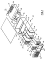
- Figure 1 is an exploded isometric view of a data storage system according to the present invention (with the top cover removed for clarity);
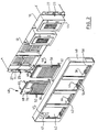
- Figure 2 is an exploded isometric view (looking from the front) of the front part of a data storage system according to the present invention;
- Figure 3 is an exploded isometric view (looking from the rear) of the front part of a data storage system according to the present invention;
- Figure 4 is a perspective view of a data storage system according to the present invention;
- Figure 1 shows a multi-media data storage system including data storage devices of two different types i.e.
tape drive 10 anddisk drive 12. Each device is removably mounted into one of fourbays 14 defined by dividing walls l6 in afirst compartment 18 of adrawer 20. Because each device is of a standard size (5.25 inch form factor), it would be theoretically possible to put a device into any one of the bays. When the drawer of figure 1 is assembled, there are two disk drives in the two left hand bays and two tape drives in the two right hand bays. Amounting plate 22 fixed onto the side of each device locates inguide rails 24 fixed to the top and bottom (not shown) inner surfaces of the drawer. Ahandle 11 on the front of the disk drive is used to insert and remove the unit from the drawer. The system also includes a power switch and indicator lamp in aunit 25 fixed at the front left-hand side of the drawer. - Behind the front compartment of the drawer is a
central fan chamber 26, the rear wall of which is defined by acentral bulkhead 28 onto which are mounted two dual side entrycentrifugal fans 30. The central bulkhead is attached to apicture frame 32 fixed in position in the drawer. Behind the central bulkhead is athird compartment 34 which houses thepower supply unit 36 which provides power for the devices and the fans. Providing the interface between the drawer and any external device is acard 37 located above thepower supply 37 which includes a number of connectors. Tape cabling (not shown for clarity) attaches to the connectors on the card and passes through the central bulkhead and connects to each of the devices. When the storage system is in operation, cooling air is forced around the devices, through the fans and through and over the power supply, exiting through slots in therear bulkhead 38 of the drawer, only theupper slots 39 being visible. - Figures 1, 2 and 3 show a
cover frame 40 which fits onto the front of the drawer by means of twobullnose catches 23 located on twoflanges 27 extending either side of the drawer front. The catches engage with two clips located in the cover frame. The cover frame has fourapertures 42, each aperture corresponding to one storage device. In figure 2, two tape drives are shown in the rightmost bays, thefront surface 44 of each tape drive protruding beyond the front of the drawer. When the drawer is assembled, and the cover frame is fixed to the drawer, the front surface of each tape drive fits into and entirely fills the corresponding aperture. The tape drive front surface sits flush with the front surface of the frame and is visible from the front of the system. - In figure 2, it can be seen that each disk drive is mounted in the bay such that a gap is defined between the front of the device and the front of the drawer. In front of each disk drive, a removable snap-in
panel louvred portion 50 comprising a number ofhorizontal slots 52 through which air passes to cool the disk drive when in operation. - Because the indicator unit 25 (shown in figure 1 but omitted from figures 2 and 3 for clarity) obscures part of the leftmost bay at the drawer front, it is not possible in the embodiment shown to position a tape drive in that particular bay. A disk drive sits in the leftmost bay, with the
unit 25 taking up some of the space between the front of the drive and the front of the drawer. As can be seen in any of the figures, the shape of the leftmost aperture in the cover frame is modified by the inclusion of acorner portion 45 in the frame. Included in this portion is aviewing slot 47 through which the indicator lamp inunit 25 can be seen. The snap-inpanel 48, described in more detail below, is suitably shaped to fit the modified aperture. In a different system design wherein there is no necessity to include a similar corner portion, and wherein the dimensions of each aperture are identical, then it would be possible to mount each device into any of the drawer device positions. - Figures 2 and 3 show the frame and snap-in panel in more detail. As can be seen in figure 2, twenty holes 54 (divided into four groups of five) are cut into the lower turned back
surface 56 of the frame, perpendicular to thefront surface 58. As can be seen in figure 3, each group of holes corresponds to one device aperture (one of the groups is obscured by panel 48). - Each snap in
panel resilient tangs 60 extending backwards from the top of the panel front surface. When the panel is mounted in the frame the tangs are forced downwards and engage with corresponding features on the top inner surface of the cover frame. Extending from the bottom of each panel front surface is a substantiallyflat member 62, divided into three sections by two slots. When the panel is mounted in the frame (shown in figure 3) the three sections engage with the lower inner surface of the frame, the slots mating with two raisedridges 64 in the frame lower surface thereby locating the panel correctly in the frame. In this way the flat member blocks off one of the four groups of holes in the cover frame, the central section covering the three holes between the ridges and the two outer sections each covering one of the holes. - For the reasons already described, snap-in
panel 48 has a different shape to theother panel type 46. The louvred front portion (66) is reverse 'L' shaped and stands proud of aflat portion 68 including an oblong shapedaperture 70 through which the indicator lamp can be seen at the front of the system.Panel 48 fits into the frame in the same way as theother panel type 46, the flat portion sitting behind thecorner portion 45 of the cover frame. - The data storage system is assembled as follows; the devices are connected to signal and power cables (not shown) from the rear, inserted into the desired bay positions and secured in place. Each snap-in panel is mounted in the cover frame in the aperture corresponding to each disk drive position and then the cover frame is fixed onto the chassis. As has been described previously, the front of each tape drive sits in its corresponding device aperture.
- When the data storage system is in operation, each disk drive is cooled by air passing through the
louvred portion 50 in the corresponding panel. Air passes through a grille behindhandle 11 and around the device through thegaps 13 between the disk drive and the walls of the bay in which the disk drive is located. Because the tape drive entirely fills the corresponding aperture in the frame and there are no openings in the front of the tape drive, the method of cooling used for the disk drives is not possible. The fans draw air through the fivecooling holes 54 in the lower surface of the cover frame and along the lower surface of the tape drive. A baffle located in the lower surface of the drawer deflects the cooling air passing along the lower surface of the tape drive over heat producing electronic components on circuit boards at the rear of the tape drive. In embodiments other than that described herein, suitably placed baffles could deflect cooling air wherever it is required. - In the embodiment described, sufficient cooling of the disk drive is obtained by the passage of air through the louvred section of the snap-in panel and flow of cooling air through the frame cooling holes is not required. Noise emanating from both fan and device radiates from these holes. In order to reduce the amount of noise at the front of the drawer, it is thus desirable that the
secondary holes 54 associated with each disk drive position should be blocked off. This is achieved by means of blankingplate 62 as already described. Other provision, not detailed here, may be required to reduce the amount of noise radiating from the louvred section of each removable panel. - In some multimedia systems it may be that a particular device does include air intakes in its front surface but these are not sufficient to cool the device satisfactorily. In this case the frame cooling holes may be used to assist with the cooling of the device, the cooling holes being designed to provide adequate cooling while reducing the amount of noise radiating from these holes.
- While the embodiment described shows two tape and disk drives it will be apparent that this invention would prove equally effective in drawers containing a different combination of the two types of device. The system could also incorporate other types of storage device not described e.g. optical disk drives.
Claims (8)
- A data storage system including:
a housing for interchangeably mounting a plurality of data storage devices of at least two different types (10,12) within a corresponding plurality of bays (16) defined within the housing;
fan means (30) for causing airflow through the plurality of bays past such devices when mounted within the housing; characterised in that the system further includes:
a cover frame (40) removably attached to the housing and having a plurality of primary apertures (42) in front of the bays to permit airflow through the bays when a first type of data storage device is mounted therein and having a plurality of secondary apertures (54) to permit airflow through the bays when a second type of data storage device is mounted therein; and
means for blocking said secondary apertures associated with selected bays having said first type of data storage device mounted therein. - A data storage system as claimed in claim 1, wherein said cover frame defines one primary aperture for each device bay (16).
- A data storage system as claimed in claim 1 or claim 2, wherein said cover frame includes at least one secondary aperture associated with each of said plurality of device bays, said at least one secondary aperture being located in at least one surface (56) of the cover frame.
- A data storage system as claimed in any preceding claim, wherein said means for blocking said secondary apertures comprises at least one removable panel (46,48) adapted to be mounted within a selected primary aperture within said cover frame and having a blanking member for blocking said secondary apertures disposed adjacent to said selected primary aperture.
- A data storage system as claimed in claim 4, wherein said at least one removable panel includes a plurality of horizontal slots disposed therein.
- A data storage system as claimed in claim 4 or claim 5, wherein the primary apertures are located in the front surface (58) of the frame and the secondary apertures are located in a second surface (56) of the frame substantially perpendicular to the front surface, the blanking member comprising a flange (62) extending rearwards from the panel front surface to block the secondary apertures.
- A data storage device as claimed in any preceding claim, the housing defining four device bays with the cover frame including four corresponding primary apertures.
- A data storage system as claimed in any preceding claim wherein the first device type is a disk drive and the second device type is a magnetic tape drive.
Applications Claiming Priority (2)
| Application Number | Priority Date | Filing Date | Title |
|---|---|---|---|
| GB9003473 | 1990-02-15 | ||
| GB9003473A GB2241101A (en) | 1990-02-15 | 1990-02-15 | Data storage system with device dependent flow of cooling air |
Publications (3)
| Publication Number | Publication Date |
|---|---|
| EP0442640A2 EP0442640A2 (en) | 1991-08-21 |
| EP0442640A3 EP0442640A3 (en) | 1992-10-28 |
| EP0442640B1 true EP0442640B1 (en) | 1995-07-26 |
Family
ID=10671074
Family Applications (1)
| Application Number | Title | Priority Date | Filing Date |
|---|---|---|---|
| EP91300880A Expired - Lifetime EP0442640B1 (en) | 1990-02-15 | 1991-02-04 | Data storage system with device dependent flow of cooling air |
Country Status (5)
| Country | Link |
|---|---|
| US (1) | US5119270A (en) |
| EP (1) | EP0442640B1 (en) |
| JP (1) | JPH0656717B2 (en) |
| DE (1) | DE69111483T2 (en) |
| GB (1) | GB2241101A (en) |
Families Citing this family (72)
| Publication number | Priority date | Publication date | Assignee | Title |
|---|---|---|---|---|
| US5274516A (en) * | 1990-09-29 | 1993-12-28 | Victor Company Of Japan, Ltd. | Multi-cassette recording and reproducing apparatus |
| US5321813A (en) | 1991-05-01 | 1994-06-14 | Teradata Corporation | Reconfigurable, fault tolerant, multistage interconnect network and protocol |
| DE9108160U1 (en) * | 1991-07-03 | 1991-10-10 | Electronicon-Gmbh, O-6500 Gera, De | |
| JPH0824222B2 (en) * | 1992-04-10 | 1996-03-06 | インターナショナル・ビジネス・マシーンズ・コーポレイション | Cooling device with air-mixer cooling plate |
| DE4218007C2 (en) * | 1992-06-01 | 1995-04-20 | Schroff Gmbh | casing |
| GB2276275A (en) * | 1993-03-20 | 1994-09-21 | Ibm | Cooling modular electrical apparatus |
| US5385487A (en) * | 1993-08-30 | 1995-01-31 | At&T Corp. | Apparatus for electrically operating devices in a controlled environment |
| US5784644A (en) * | 1995-02-02 | 1998-07-21 | Larabell; Henri J. | Carrier for connecting device using electrical display device for indicating SCSI ID and controller ID of the attached device on the carriers facial assembly |
| DE19535492A1 (en) * | 1995-09-23 | 1997-03-27 | Winotek Handelsgesellschaft Mb | Device for holding hard discs |
| US5542757A (en) * | 1995-10-19 | 1996-08-06 | Chang; Chia-Chi | Front panel assembly of a diskdrive case |
| USD382549S (en) * | 1995-11-06 | 1997-08-19 | Apple Computer, Inc. | Ventilation cover |
| US5768101A (en) * | 1996-12-20 | 1998-06-16 | Compaq Computer Corporation | Portable computer docking base with ducted interior cooling air passsage |
| KR19980019402A (en) * | 1998-03-16 | 1998-06-05 | 천기완 | CPU COOLING DEVICE OF PC |
| US6650535B1 (en) * | 1999-07-23 | 2003-11-18 | Dell Products L.P. | Fanless power supply |
| US6259601B1 (en) | 1999-09-30 | 2001-07-10 | Dell Usa, L.P. | Apparatus for providing docking station assisted cooling of a portable computer |
| US6412002B1 (en) | 1999-11-15 | 2002-06-25 | Ncr Corporation | Method and apparatus for selecting nodes in configuring massively parallel systems |
| US6418526B1 (en) | 1999-11-15 | 2002-07-09 | Ncr Corporation | Method and apparatus for synchronizing nodes in massively parallel systems |
| US6519697B1 (en) | 1999-11-15 | 2003-02-11 | Ncr Corporation | Method and apparatus for coordinating the configuration of massively parallel systems |
| US6401805B1 (en) | 1999-12-22 | 2002-06-11 | Ncr Corporation | Integrated venting EMI shield and heatsink component for electronic equipment enclosures |
| US6549405B2 (en) * | 2000-06-09 | 2003-04-15 | Vertex Electronic Products, Inc. | Electronic chassis |
| US6437976B1 (en) * | 2000-06-15 | 2002-08-20 | Compaq Information Technologies Group, L.P. | Readily attachable and removable faceplates for a computer housing |
| US6392884B1 (en) * | 2000-08-01 | 2002-05-21 | Shin Jiuh Corp. | Housing assembly for extractable redundant array of independent disks |
| US6480379B1 (en) * | 2000-09-29 | 2002-11-12 | Hewlett-Packard Company | Removable component filter |
| DE20018740U1 (en) * | 2000-10-26 | 2000-12-28 | Deutsche Telephonwerk Kabel | Housing for telecommunications systems |
| US6523916B2 (en) | 2000-12-22 | 2003-02-25 | Aurora Networks, Inc. | Chassis with repositionable plates |
| US6459578B1 (en) | 2001-04-24 | 2002-10-01 | Agilent Technologies, Inc. | Chassis having reduced acoustic noise and electromagnetic emissions and method of cooling components within a chassis |
| US6522537B2 (en) * | 2001-07-18 | 2003-02-18 | Portwell Inc. | Snap-in computer casing structure |
| US20030090182A1 (en) * | 2001-11-14 | 2003-05-15 | Johnson Kristianne E. | Interchangeable customized bezel |
| US7054144B2 (en) * | 2003-05-23 | 2006-05-30 | Dell Products L.P. | Modular enclosure locking bezel and method of use |
| US7201651B2 (en) * | 2004-12-22 | 2007-04-10 | Chi-Min Su | Louver heat vent for chassis of computer |
| US7344643B2 (en) * | 2005-06-30 | 2008-03-18 | Siemens Water Technologies Holding Corp. | Process to enhance phosphorus removal for activated sludge wastewater treatment systems |
| CN200969073Y (en) * | 2006-11-13 | 2007-10-31 | 鸿富锦精密工业(深圳)有限公司 | Computer cabinet |
| US20090097197A1 (en) * | 2007-10-11 | 2009-04-16 | Ming-Chu Chen | Side plate of housing |
| US7639486B2 (en) * | 2007-12-13 | 2009-12-29 | International Business Machines Corporation | Rack system providing flexible configuration of computer systems with front access |
| US8549912B2 (en) | 2007-12-18 | 2013-10-08 | Teradyne, Inc. | Disk drive transport, clamping and testing |
| US7996174B2 (en) | 2007-12-18 | 2011-08-09 | Teradyne, Inc. | Disk drive testing |
| US8041449B2 (en) | 2008-04-17 | 2011-10-18 | Teradyne, Inc. | Bulk feeding disk drives to disk drive testing systems |
| US8117480B2 (en) | 2008-04-17 | 2012-02-14 | Teradyne, Inc. | Dependent temperature control within disk drive testing systems |
| US20090262455A1 (en) * | 2008-04-17 | 2009-10-22 | Teradyne, Inc. | Temperature Control Within Disk Drive Testing Systems |
| US7945424B2 (en) | 2008-04-17 | 2011-05-17 | Teradyne, Inc. | Disk drive emulator and method of use thereof |
| US8095234B2 (en) | 2008-04-17 | 2012-01-10 | Teradyne, Inc. | Transferring disk drives within disk drive testing systems |
| US8238099B2 (en) | 2008-04-17 | 2012-08-07 | Teradyne, Inc. | Enclosed operating area for disk drive testing systems |
| US8305751B2 (en) | 2008-04-17 | 2012-11-06 | Teradyne, Inc. | Vibration isolation within disk drive testing systems |
| US8160739B2 (en) | 2008-04-17 | 2012-04-17 | Teradyne, Inc. | Transferring storage devices within storage device testing systems |
| US8102173B2 (en) | 2008-04-17 | 2012-01-24 | Teradyne, Inc. | Thermal control system for test slot of test rack for disk drive testing system with thermoelectric device and a cooling conduit |
| US7848106B2 (en) | 2008-04-17 | 2010-12-07 | Teradyne, Inc. | Temperature control within disk drive testing systems |
| CN102112887B (en) | 2008-06-03 | 2015-06-10 | 泰拉丁公司 | Processing storage devices |
| US7995349B2 (en) | 2009-07-15 | 2011-08-09 | Teradyne, Inc. | Storage device temperature sensing |
| US8466699B2 (en) | 2009-07-15 | 2013-06-18 | Teradyne, Inc. | Heating storage devices in a testing system |
| US7920380B2 (en) | 2009-07-15 | 2011-04-05 | Teradyne, Inc. | Test slot cooling system for a storage device testing system |
| US8628239B2 (en) | 2009-07-15 | 2014-01-14 | Teradyne, Inc. | Storage device temperature sensing |
| US8687356B2 (en) | 2010-02-02 | 2014-04-01 | Teradyne, Inc. | Storage device testing system cooling |
| US8116079B2 (en) | 2009-07-15 | 2012-02-14 | Teradyne, Inc. | Storage device testing system cooling |
| US8547123B2 (en) | 2009-07-15 | 2013-10-01 | Teradyne, Inc. | Storage device testing system with a conductive heating assembly |
| CN102244995A (en) * | 2010-05-11 | 2011-11-16 | 鸿富锦精密工业(深圳)有限公司 | Electronic device shell |
| US9779780B2 (en) | 2010-06-17 | 2017-10-03 | Teradyne, Inc. | Damping vibrations within storage device testing systems |
| US8687349B2 (en) | 2010-07-21 | 2014-04-01 | Teradyne, Inc. | Bulk transfer of storage devices using manual loading |
| US9001456B2 (en) | 2010-08-31 | 2015-04-07 | Teradyne, Inc. | Engaging test slots |
| US9372515B2 (en) | 2013-03-14 | 2016-06-21 | Evtron, Inc. | Heat and airflow management in a data storage device |
| US9459312B2 (en) | 2013-04-10 | 2016-10-04 | Teradyne, Inc. | Electronic assembly test system |
| US9894807B2 (en) * | 2015-01-27 | 2018-02-13 | International Business Machines Corporation | Changeable, airflow venting cover assembly for an electronics rack |
| US10725091B2 (en) | 2017-08-28 | 2020-07-28 | Teradyne, Inc. | Automated test system having multiple stages |
| US11226390B2 (en) | 2017-08-28 | 2022-01-18 | Teradyne, Inc. | Calibration process for an automated test system |
| US10845410B2 (en) | 2017-08-28 | 2020-11-24 | Teradyne, Inc. | Automated test system having orthogonal robots |
| US10948534B2 (en) | 2017-08-28 | 2021-03-16 | Teradyne, Inc. | Automated test system employing robotics |
| US10983145B2 (en) | 2018-04-24 | 2021-04-20 | Teradyne, Inc. | System for testing devices inside of carriers |
| US10775408B2 (en) | 2018-08-20 | 2020-09-15 | Teradyne, Inc. | System for testing devices inside of carriers |
| US11953519B2 (en) | 2020-10-22 | 2024-04-09 | Teradyne, Inc. | Modular automated test system |
| US11754622B2 (en) | 2020-10-22 | 2023-09-12 | Teradyne, Inc. | Thermal control system for an automated test system |
| US11754596B2 (en) | 2020-10-22 | 2023-09-12 | Teradyne, Inc. | Test site configuration in an automated test system |
| US11867749B2 (en) | 2020-10-22 | 2024-01-09 | Teradyne, Inc. | Vision system for an automated test system |
| US11899042B2 (en) | 2020-10-22 | 2024-02-13 | Teradyne, Inc. | Automated test system |
Family Cites Families (15)
| Publication number | Priority date | Publication date | Assignee | Title |
|---|---|---|---|---|
| US2380026A (en) * | 1943-08-06 | 1945-07-10 | Standard Telephones Cables Ltd | Cooling device for metal rectifiers |
| US3188524A (en) * | 1962-09-20 | 1965-06-08 | Lockheed Aircraft Corp | High density circuit card packaging |
| US3298195A (en) * | 1965-10-15 | 1967-01-17 | Nicholas M Raskhodoff | Module cooling system |
| US3592260A (en) * | 1969-12-05 | 1971-07-13 | Espey Mfg & Electronics Corp | Heat exchanger with inner guide strip |
| FR2343974A1 (en) * | 1976-03-10 | 1977-10-07 | Honeywell Bull Soc Ind | VENTILATION ENCLOSURE |
| DE3019668A1 (en) * | 1980-05-22 | 1981-11-26 | SIEMENS AG AAAAA, 1000 Berlin und 8000 München | DEVICE FOR DETECTING AND PROCESSING ELECTRICAL SIGNALS |
| US4754397A (en) * | 1985-02-15 | 1988-06-28 | Tandem Computers Incorporated | Fault tolerant modular subsystems for computers |
| GB8523161D0 (en) * | 1985-09-19 | 1985-10-23 | Bicc Vero Electronics Ltd | Enclosure |
| US4728160A (en) * | 1986-10-22 | 1988-03-01 | Digital Equipment Corporation | Cabinet for a computer assembly |
| US4702154A (en) * | 1987-01-28 | 1987-10-27 | Dodson Douglas A | Cooling system for personal computer |
| US4748540A (en) * | 1987-04-24 | 1988-05-31 | Honeywell Bull Inc. | Compact packaging of electronic equipment within a small profile enclosure |
| US4894749A (en) * | 1987-08-31 | 1990-01-16 | AT&T Information Systems Inc American Telephone and Telegraph Company | Option slot filler board |
| US4888549A (en) * | 1987-10-30 | 1989-12-19 | Wilson Laboratories, Inc. | System for testing individually a plurality of disk drive units |
| US4870643A (en) * | 1987-11-06 | 1989-09-26 | Micropolis Corporation | Parallel drive array storage system |
| US4937806A (en) * | 1988-02-12 | 1990-06-26 | Mdb Systems, Inc. | Shock-isolated portable mass data storage device |
-
1990
- 1990-02-15 GB GB9003473A patent/GB2241101A/en not_active Withdrawn
- 1990-11-27 US US07/618,781 patent/US5119270A/en not_active Expired - Fee Related
-
1991
- 1991-02-04 DE DE69111483T patent/DE69111483T2/en not_active Expired - Fee Related
- 1991-02-04 EP EP91300880A patent/EP0442640B1/en not_active Expired - Lifetime
- 1991-02-07 JP JP3036665A patent/JPH0656717B2/en not_active Expired - Lifetime
Also Published As
| Publication number | Publication date |
|---|---|
| GB9003473D0 (en) | 1990-04-11 |
| JPH0656717B2 (en) | 1994-07-27 |
| EP0442640A3 (en) | 1992-10-28 |
| EP0442640A2 (en) | 1991-08-21 |
| JPH056652A (en) | 1993-01-14 |
| DE69111483T2 (en) | 1996-03-07 |
| US5119270A (en) | 1992-06-02 |
| DE69111483D1 (en) | 1995-08-31 |
| GB2241101A (en) | 1991-08-21 |
Similar Documents
| Publication | Publication Date | Title |
|---|---|---|
| EP0442640B1 (en) | Data storage system with device dependent flow of cooling air | |
| EP0442642B1 (en) | Multi unit electrical apparatus with forced air cooling | |
| US5680295A (en) | Ventilated backplane for mounting disk drives in computer systems | |
| US4728160A (en) | Cabinet for a computer assembly | |
| US5410448A (en) | Adaptive cooling system | |
| US5828546A (en) | Device cover and ejection apparatus and method | |
| US9084375B2 (en) | Airflow module and data storage device enclosure | |
| EP0617570B1 (en) | Modular housing | |
| US5828547A (en) | Computer case having slidably insertable drive housing with U-shaped mounting bracket having inwardly projecting pins on two opposed legs | |
| US6285548B1 (en) | Face plate for a chassis for high frequency components | |
| US6018456A (en) | Enclosure for removable computer peripheral equipment | |
| US5526228A (en) | Computer system unit with acoustic dampening cooling fan shroud panel | |
| US5333097A (en) | Disk drive holder and interconnection system | |
| KR930001355B1 (en) | Compact packaging of electronic equipment within a small profile enclosure | |
| US4977532A (en) | Industrial computer system with removable equipment drawer | |
| US6833995B1 (en) | Enclosure having a divider wall for removable electronic devices | |
| US5524104A (en) | Compact disk drive arrangement with one disk mounted on top of another | |
| EP0132152B1 (en) | Modular computer system | |
| US6424526B1 (en) | High-density disk-array packaging apparatus and method | |
| CN1959835B (en) | Driver shell frame and data storage system concluding the same | |
| US20040001313A1 (en) | Electrode apparatus having a front door covering a front surface of a housing | |
| JP2799183B2 (en) | Collective disk storage device | |
| JP2758317B2 (en) | Electronic device cooling structure | |
| JPH09321451A (en) | Information recording and reproducing device | |
| JPH04371000A (en) | Cooling structure for electronic device unit |
Legal Events
| Date | Code | Title | Description |
|---|---|---|---|
| PUAI | Public reference made under article 153(3) epc to a published international application that has entered the european phase |
Free format text: ORIGINAL CODE: 0009012 |
|
| AK | Designated contracting states |
Kind code of ref document: A2 Designated state(s): DE FR GB |
|
| 17P | Request for examination filed |
Effective date: 19911211 |
|
| PUAL | Search report despatched |
Free format text: ORIGINAL CODE: 0009013 |
|
| AK | Designated contracting states |
Kind code of ref document: A3 Designated state(s): DE FR GB |
|
| 17Q | First examination report despatched |
Effective date: 19930730 |
|
| GRAA | (expected) grant |
Free format text: ORIGINAL CODE: 0009210 |
|
| AK | Designated contracting states |
Kind code of ref document: B1 Designated state(s): DE FR GB |
|
| REF | Corresponds to: |
Ref document number: 69111483 Country of ref document: DE Date of ref document: 19950831 |
|
| ET | Fr: translation filed | ||
| PG25 | Lapsed in a contracting state [announced via postgrant information from national office to epo] |
Ref country code: GB Effective date: 19960204 |
|
| PLBE | No opposition filed within time limit |
Free format text: ORIGINAL CODE: 0009261 |
|
| STAA | Information on the status of an ep patent application or granted ep patent |
Free format text: STATUS: NO OPPOSITION FILED WITHIN TIME LIMIT |
|
| 26N | No opposition filed | ||
| GBPC | Gb: european patent ceased through non-payment of renewal fee |
Effective date: 19960204 |
|
| PG25 | Lapsed in a contracting state [announced via postgrant information from national office to epo] |
Ref country code: FR Effective date: 19961031 |
|
| PG25 | Lapsed in a contracting state [announced via postgrant information from national office to epo] |
Ref country code: DE Effective date: 19961101 |
|
| REG | Reference to a national code |
Ref country code: FR Ref legal event code: ST |