EP0442501A2 - Photographic film cassette - Google Patents
Photographic film cassette Download PDFInfo
- Publication number
- EP0442501A2 EP0442501A2 EP91102109A EP91102109A EP0442501A2 EP 0442501 A2 EP0442501 A2 EP 0442501A2 EP 91102109 A EP91102109 A EP 91102109A EP 91102109 A EP91102109 A EP 91102109A EP 0442501 A2 EP0442501 A2 EP 0442501A2
- Authority
- EP
- European Patent Office
- Prior art keywords
- cassette
- film
- shell
- spool
- photographic film
- Prior art date
- Legal status (The legal status is an assumption and is not a legal conclusion. Google has not performed a legal analysis and makes no representation as to the accuracy of the status listed.)
- Granted
Links
Images


Classifications
-
- G—PHYSICS
- G03—PHOTOGRAPHY; CINEMATOGRAPHY; ANALOGOUS TECHNIQUES USING WAVES OTHER THAN OPTICAL WAVES; ELECTROGRAPHY; HOLOGRAPHY
- G03B—APPARATUS OR ARRANGEMENTS FOR TAKING PHOTOGRAPHS OR FOR PROJECTING OR VIEWING THEM; APPARATUS OR ARRANGEMENTS EMPLOYING ANALOGOUS TECHNIQUES USING WAVES OTHER THAN OPTICAL WAVES; ACCESSORIES THEREFOR
- G03B17/00—Details of cameras or camera bodies; Accessories therefor
- G03B17/28—Locating light-sensitive material within camera
- G03B17/30—Locating spools or other rotatable holders of coiled film
-
- G—PHYSICS
- G03—PHOTOGRAPHY; CINEMATOGRAPHY; ANALOGOUS TECHNIQUES USING WAVES OTHER THAN OPTICAL WAVES; ELECTROGRAPHY; HOLOGRAPHY
- G03B—APPARATUS OR ARRANGEMENTS FOR TAKING PHOTOGRAPHS OR FOR PROJECTING OR VIEWING THEM; APPARATUS OR ARRANGEMENTS EMPLOYING ANALOGOUS TECHNIQUES USING WAVES OTHER THAN OPTICAL WAVES; ACCESSORIES THEREFOR
- G03B2217/00—Details of cameras or camera bodies; Accessories therefor
- G03B2217/26—Holders for containing light-sensitive material and adapted to be inserted within the camera
- G03B2217/261—Details of spools
-
- G—PHYSICS
- G03—PHOTOGRAPHY; CINEMATOGRAPHY; ANALOGOUS TECHNIQUES USING WAVES OTHER THAN OPTICAL WAVES; ELECTROGRAPHY; HOLOGRAPHY
- G03B—APPARATUS OR ARRANGEMENTS FOR TAKING PHOTOGRAPHS OR FOR PROJECTING OR VIEWING THEM; APPARATUS OR ARRANGEMENTS EMPLOYING ANALOGOUS TECHNIQUES USING WAVES OTHER THAN OPTICAL WAVES; ACCESSORIES THEREFOR
- G03B2217/00—Details of cameras or camera bodies; Accessories therefor
- G03B2217/26—Holders for containing light-sensitive material and adapted to be inserted within the camera
- G03B2217/266—Thrust-type cartridges
-
- G—PHYSICS
- G03—PHOTOGRAPHY; CINEMATOGRAPHY; ANALOGOUS TECHNIQUES USING WAVES OTHER THAN OPTICAL WAVES; ELECTROGRAPHY; HOLOGRAPHY
- G03B—APPARATUS OR ARRANGEMENTS FOR TAKING PHOTOGRAPHS OR FOR PROJECTING OR VIEWING THEM; APPARATUS OR ARRANGEMENTS EMPLOYING ANALOGOUS TECHNIQUES USING WAVES OTHER THAN OPTICAL WAVES; ACCESSORIES THEREFOR
- G03B2217/00—Details of cameras or camera bodies; Accessories therefor
- G03B2217/26—Holders for containing light-sensitive material and adapted to be inserted within the camera
- G03B2217/268—Unloading the cartridge from the camera; Loading the cartridge into the camera
Definitions
- the present invention relates to a photographic film cassette, more particularly to an improvement of a self-advancing film cassette capable of initially advancing the film smoothly by rotating the spool.
- a rewinding shaft provided in a film loading chamber of the camera rotates the spool to rewind the film in the cassette shell.
- a recess is formed on an end of the spool for being fitted on a fork formed on the rewinding shaft.
- a pair of projections are formed inside the recess for rotating the spool in contact with the fork in rotation.
- a leader of the film is protruded from the cassette shell.
- a film cassette comprises: a receiving recess formed on an end of the spool for receiving an end of a rewinding shaft provided with a camera for rotating the spool by being coupled with the spool end; coupling means formed in the receiving recess for receiving a driving force from the rewinding shaft; and an inclined surface formed on the coupling means for guiding an insertion of the rewinding shaft into the receiving recess.
- a film cassette further comprises: a first shell component being a molded part for constituting the cassette shell, with which at least a part of the film passage mouth is integrated; a second shell component joined to the first shell component for constituting the cassette shell; and positioning means integrated with the first shell component for positioning the cassette shell in contact with receiving means formed in a film loading chamber in a camera.
- the film can be reliably advanced to the outside by slipping the outermost turn of the wound film smoothly in contact with the annular ridges. Precision in the position is improved between the film passage mouth and the positioning means even in assembly. Accordingly, the contact of the positioning means with the receiving means in the film loading chamber makes it possible to position the cassette shell precisely in the film loading chamber.
- a cassette shell 2 consists of an upper shell half 3 and a lower shell half 4 each molded from plastics of a light-tight property, and rotatably contains a spool 6 with photographic film 5, e.g. negative film, wound thereabout.
- the ends of the spool 6 do not project from the cassette shell 2, but are included in the outline of the cassette shell 2 underneath so as to prevent a user from rotating the spool 6 only with his fingers.
- a recess 8 is formed with five inclined planes 9 in the shape of a frustrum of a regular pentagonal pyramid having a decreasing space in the direction toward the inside of the recess 8.
- the recess 8 receives and is coupled to a coupling member 11 provided in a camera in the shape of a frustrum of a regular pentagonal pyramid, as illustrated in Fig. 2, which is formed on the tip of a rewinding shaft 10 of the camera.
- a recess 8a may be formed in the shape of a frustrum of a regular triangular pyramid as illustrated in Fig. 3.
- a coupling member 11a in this case needs to be a frustrum of a regular triangular pyramid as illustrated in Fig. 4.
- a recess of the end of the spool 6 and a coupling member of the rewinding shaft 10 may also formed in the shape of a frustrum of another regular polygonal pyramid such as a regular quadrangular pyramid.
- the rewinding shaft 10 is slidably inserted in a bearing hole 16 formed on an inner surface 15 of a film loading chamber of the camera.
- the lower end of the rewinding shaft 10 is fitted in a receiving hole 18 formed on a camera body 17.
- a spring 19 is inserted in the receiving hole 18, and upwardly biases the rewinding shaft 10.
- a gear 20 is integrated with the rewinding shaft 10 in mesh with a driving gear 21 which is driven by a driving mechanism of the camera.
- the lower end of the rewinding shaft 10 never slips off the receiving hole 18, because a side of the gear 20 would abut the lower portion of the bearing hole 16 even when the gear 20 slides upwardly.
- the driving gear 21 has a large thickness such as to prevent the gear 20 from disengaging therewith even when the rewinding shaft 10 vertically slides.
- the driving force of the driving mechanism is reliably transmitted to the rewinding shaft 10.
- the driving force of the rewinding shaft 10 is transmitted to the spool 6 by the five inclined planes 9 in contact with the side faces of the coupling member 11.
- One fifth as large as the driving force of the rewinding shaft 10 is applied to each of the inclined planes 9.
- a pair of annular ridges 25 are formed on the inner surface of the cassette shell 2.
- the ridges 25 serve to press the outermost turn of the wound film 5 so as to prevent the film roll from loosening.
- the camera body 17 with a back door 35 open is provided with an exposure aperture 36.
- the back door 35 is provided with a pressure plate 37 and a film guide 38.
- the pressure plate 37 presses the film 5 positioned on the exposure aperture 36 to keep the film 5 flat, and forms a film passageway 39 in the space defined by the exposure aperture 36.
- a free sprocket 40 to be rotated by the film 5 through its perforations is provided on the upper side of the exposure aperture 36 in order to detect the feeding amount of the film 5.
- a film loading chamber 41 and a film take-up chamber 42 are each formed on left and right sides of the exposure aperture 36.
- the above coupling member 11 is exposed in the inner position of the film loading chamber 41.
- the cassette shell 2 having the film 5 is inserted in the camera body 17 in the direction indicated by the arrow through an opening 43 formed on the bottom of the film loading chamber 41.
- a take-up spool 45 at the center of the film take-up chamber 42.
- the take-up spool 45 is driven by the above-described driving mechanism of the camera in order to wind up the film 5 taken up by the guide of the film guide 38.
- the cassette shell 2 With the back door 35 open, the cassette shell 2 is inserted in the opening 43 in the direction of advancing the recess 8.
- the inclined planes 9 are guided by the lateral sides of the coupling member 11. Even when not fitted on the sides of the coupling member 11, the inclined planes 9 can be reliably fitted thereon by rotating the cassette shell 2 through at least 72 degrees.
- the coupling member 11 When the coupling member 11 is fitted in the recess 8, the attachment of the inclined planes 9 to the sides of the coupling member 11 keeps the spool 6 axially coincident with the rewinding shaft 10.
- the purpose of ensuring this operation to determine the size of the film loading chamber 41 as slightly larger than that of the cassette shell 2 in the innermost position of the film loading chamber 41. It is also preferable to provide a mechanism for supporting the cassette shell 2 with a spring in the film loading chamber 41. As the cassette shell 2 can be manually rearranged even in the lack of axial coincidence, such a mechanism makes possible the axial coincidence between the spool 6 and the rewinding shaft 11.
- the driving mechanism rotates the driving gear 21 and the take-up spool 45.
- the driving gear 21 rotates the spool 6 through a rewinding shaft 10 in the unwinding direction.
- the rotary axis of the spool 6 constitutes the center of the annular ridge 25 so as to prevent the outermost turn of the wound film 5 from being partially scratched by the annular ridge 25.
- the slipping friction between the film 5 and the annular ridge 25 is kept constant without a partially excessive increase in deviation.
- the leading end of the film 5 Upon rotating the spool 6 in the unwinding direction, the leading end of the film 5 is advanced smoothly to the outside of the cassette shell 2 through the film passage mouth 28, and fed to the film take-up chamber 42 through the film passageway 39.
- the take-up spool 45 winds up the film 5 from the cassette shell 2.
- the take-up spool 45 Upon winding up a predetermined length of the film 5, the take-up spool 45 is stopped to position a first frame at the exposure aperture 36 on standby for taking a photograph. The film 5 is thereafter wound up on the take-up spool 45 for each exposure.
- the driving mechanism of the camera rotates the driving gear 21 in the direction opposite to feeding the film 5.
- the spool 6 is rotated in the rewinding direction to rewind the film 5 from the film take-up chamber 42 into the cassette shell 2.
- the end of a spool 50 has a recess 51 in the shape of a frustrum of a cone, in which an arresting cutoff 53 is formed on a slope 51 defining the inner surface of the recess 51.
- a coupling portion 54 is to be inserted in the recess 51.
- the coupling portion 54 is formed on the upper end of the rewinding shaft 10 in the shape of a frustrum of a cone corresponding to the recess 51.
- a metal arresting member 56 is provided on the coupling member 54 to be biased by a spring 55 so as to retractably project from the slope of the coupling member 54.
- the arresting member 56 is fitted in the arresting cutoff 53 to transmit reliably the rotation of the rewinding shaft 10 to the spool 50 without slipping the coupling member 54 in the recess 51.
- With the coupling member 54 fitted on the spool 50 attachment of the slope 52 to the slope of the coupling member 54 makes the spool 50 axially coincident with the coupling member 54.
- engagement between the arresting member 56 and the arresting cutoff 53 transmits the rotary force of the rewinding shaft 10 to the spool 50 in the present embodiment, the rotary force may also be transmitted by engagement of a number of grooves formed on the slope 52 and the slope of the coupling member 54 in the shape similar to a bevel gear and a correspondent receiving recess.
- a cylindrical recess 61 is formed on an end of a spool 60.
- the inner surface of the recess 61 is provided with a pair of contact plates 63 having inclined planes 62 formed thereon.
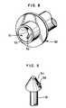
- the spool 60 is rotated by the rewinding shaft 10 as illustrated in Fig. 12.
- the tip of the rewinding shaft 10 has a coupling member 64 in the shape of a frustrum of a cone to be guided by the inclined planes 62.
- a pair of projections 65 are formed on the side slope of the coupling member 64 for pressing the contact plates 63. It is noted that the projections may also be provided with the coupling portion 64 to retractably project therefrom by being biased by a spring contained therein.
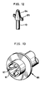
- the cylindrical recess 61 similar to that of the third embodiment is formed on the end of a spool 66.
- the inner surface of the recess 61 is provided with four contact plates 67 similar to the contact plates 63.
- the spool 66 can be rotated by the rewinding shaft 10 as illustrated in Fig. 12 having the coupling member 64.
- the coupling member 64 may also have four projections like the projections 65 to transmit the rotary force of the rewinding shaft 10 in the four positions.
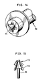
- a crossed recess 71 is formed on the end of a spool 70 in the shape having a decreasing space in the direction toward the inside of the crossed recess 71.
- the spool 70 is rotated by the rewinding shaft 10 as illustrated in Fig. 15.
- the tip of the rewinding shaft 10 has a coupling member 72 in the shape the same as a tip of a cross-point screwdriver, and is provided with four radial projections 73.
- the crossed recess 71 guides the rewinding shaft 10 therein to be fitted thereon.
- the coupling member 72 is in mesh by means of the four radial projections 73 upon rotating the rewinding shaft 10.
- the radial projections 73 equally presses the inside of the crossed recess 71 to rotate the spool 70.
- FIGs. 16 and 17 illustrate a sixth preferred embodiment of the inventive film cassette, which is advantageous in convenience for positioning the film passage mouth properly in the camera.
- a cassette shell 82 consists of the upper shell half 3 and a lower shell half 91 both molded from light-tight plastics.
- a spool 84 with the film 5 wound thereabout is rotatably contained in the cassette shell 82.
- the cassette shell 82 is also provided with the two annular ridges 25 having the separation claws 26 on its inner surface.
- a tongue 92 is formed integratedly on the edge of the upper shell half 3 for juncture except for the edge defining the film passage mouth 28 so as to be attached to the corresponding edge of the lower shell half 91, and serves to shield the juncture from light as well as to join the upper and lower shell halves 3 and 91.
- the joining method there are known adhesion by means of an adhesive agent, and welding by partially melting the shell halves with ultrasonic or dielectric heating, in order to intensify the junction and improve the light shielding condition.
- the circumferential surface of the lower shell half 91 is provided with a two chamfered portions defining first and second positioning planes 93 and 94 to be in contact with an inner surface of the film loading chamber of a camera as described below.
- the first positioning plane 93 is formed on the bottom of the lower shell half 91.
- the second positioning plane is 94 formed on the side of the lower shell half 91 vertically to the first positioning planes 93. It is noted that, although the cassette shell 2 according to the present embodiment consists of the upper and lower shell halves 3 and 91, it may also consist of a cylindrical shell component with only one end face open and a cap component to be fitted thereon. The cylindrical component then must have the film passage mouth and the two positioning planes formed on itself.
- Partial openings 95 and 96 are formed on the shell halves 3 and 91, and define a bearing aperture of a diameter substantially equal to that of the spool 84 to rotatably support the ends of the spool 84 with the shell halves 3 and 91 joined together.
- the ends of the spool 84 do not project from the cassette shell 82, as is the case of the spool 6 illustrated in Fig. 1.
- a lock mechanism for temporarily stopping the spool 84 as illustrated in Fig. 18, it is possible to prevent the spool 84 from rotating while carrying the film cassette and to prevent the film from loosening excessively.
- This lock mechanism consists of a recess 84a formed on the circular surface of the spool 84 and a locking claw 91a slidably provided with the lower shell half 91. The locking claw 91a is initially fitted in the recess 84a at the time of shipment from the factory.
- a camera for use with the above-described film cassette is now described with reference to Fig. 19.
- a chamber door 101 in the shape of a letter L is swingably mounted on a camera body 100 on the left side. With the chamber door 101 open, a film loading chamber 102 appears.
- the inner surface of the film loading chamber 102 includes first and second receiving planes 103 and 104 to be in contact each with the first and second positioning planes 93 and 94 for positioning the inserted cassette shell 82 in the film loading chamber 102.
- a passage mouth receiver 105 is formed inside the film loading chamber 102 in a rear position in the camera body for receiving the film passage mouth 28. At the inside of the passage mouth receiver 105, a film inserting mouth 106 is formed for passing therethrough the film 5 advanced from inside the cassette shell 82.
- Resilient members e.g. sponges 107 and 108 are mounted on the inside of the chamber door 101. When the chamber door 101 is closed, the sponges 107 and 108 press the cassette shell 82 on the first and second receiving planes 103 and 104. If a window is formed in the chamber door 101 for allowing reading data indicated on the cassette shell as to the film from outside the camera body, then a sponge may also cover the circumference of the window in light-tight fashion.
- a taking lens 110 is mounted on the camera body 110 at the center on the front side.
- the exposure aperture 36 has a pair of rails 112 for guiding the film 5 along the direction of feeding the film 5.
- the guide rails 112 define the film passageway 39 connected to the film inserting mouth 106.
- the pressure plate 37 is biased by a spring 114 from behind to be in contact with the guide rails 112.
- the sprocket 40 is a free sprocket for detecting the feeding amount of film 5, but may instead be a driving sprocket for feeding the film 5 to the film take-up chamber 42 by means of the perforations in the leader of the film 5.
- the rear side of the film take-up chamber 42 supports a swingable guide member 120 biased by a spring 119 in the clockwise direction in order to guide the leader of the film 5 to the film take-up spool 45 from the film passageway 39.
- the cassette shell 82 With the chamber door 101 open, the cassette shell 82 is inserted in the film loading chamber 102 while directing the film passage mouth 28 to the center of the camera body 100.
- the first positioning plane 93 is kept in contact with the first receiving plane 103.
- the cassette shell 82 is pressed by the sponge 108 and slid to the right in the film loading chamber 102.
- the second positioning plane 94 comes in contact with the second receiving plane 104.
- the cassette shell 82 When the chamber door 101 is completely closed, the cassette shell 82 is pressed toward the front of the camera body 100 by the sponge 107 to press the first positioning plane 93 on the first receiving plane 103.
- the cassette shell 82 is positioned in the film loading chamber 102 such that the film passage mouth 28 is properly positioned on the film inserting mouth 106.
- the leader of the film 5 is advanced after the chamber door 101 is closed, reaches the take-up spool 45, and is wound up thereon.
- the feeding amount of the film 5 fed from the cassette shell 82 is detected by the free sprocket 40 rotated in engagement with the perforations of the film 5. If a driving sprocket is used instead of the free sprocket 40, the sprocket is released for rotation by a mechanism such as a clutch in order to make it possible to detect the perforations.
- a cassette shell 125 consists of the upper shell half 3 and a lower shell half 127 formed to have a portion of the film passage mouth 28.
- Positioning recesses 128 are formed on both end faces of the lower shell half 127 in the shape forming right angle.
- Fig. 21 illustrates a camera loaded with the film cassette illustrated in Fig. 20.
- a camera body 130 has the chamber door 101 in a swingable state. With the chamber door 101 open, the film loading chamber 131 appears.
- the inner wall of the film loading chamber 131 is provided with receiving projections 132 each forming right angle of which one side is parallel to an optical axis of the taking lens 110 and the other side is vertical to this side.
- the receiving projections 132 are fitted in the positioning recesses 128 of the cassette shell 125 inserted in the film loading chamber 131 so as to position the film passage mouth 28 precisely at the film inserting mouth 106.
- a cassette shell 135 consists of the upper shell half 3 and a lower shell half 137.
- positioning projections 138 are formed in the shape of a letter T on both end faces of the lower shell half 137 in order to position the cassette shell 125.
- a camera body 140 is provided with a chamber door 141 on the back side.
- the chamber door 141 has a sponge 142 on its inner side.
- a film loading chamber 143 is formed inside the chamber door 141.
- the size of the film loading chamber 143 in the direction of feeding the film 5 is determined substantially the same as the diameter of the cassette shell 135.
- a pair of supporting members 144 are formed on the inner wall of the film loading chamber 143 for contact with the end faces of the inserted cassette shell 135.
- Recesses 145 are formed respectively on the supporting members 144 for being fitted on the lower ends of the positioning projections 138.
- the cassette shell 135 When the cassette shell 135 is loaded in the film loading chamber 143, the cassette shell 135 is inserted from behind the camera body 140 with the chamber door 141 open. As the film passage mouth 28 is held to keep the direction vertical to that of inserting the cassette shell 135, the inner wall of the film loading chamber 143 restricts the inserting direction so as to fit the positioning projections 138 in the recesses 145. When the chamber door 141 is closed, the cassette shell 135 is pressed by the sponge 142 and positioned in the film loading chamber 143 so as to position the film passage mouth 28 precisely on the film inserting mouth 106.
- a camera body 150 is provided with a chamber door 151 on the lateral side.
- the chamber door 151 has a sponge 152 on its inner side.
- a film loading chamber 153 is formed rightward inside the chamber door 151.
- a spring 154 is provided inside the rear wall of the film loading chamber 153 for pressing the inserted cassette shell 135 toward the front of the camera body 150.
- a pair of supporting members 155 are formed on the inner wall of the film loading chamber 153 for contact with the end faces of the inserted cassette shell 135.
- Recesses 156 are formed respectively on the supporting members 155 for being fitted on the right ends of the positioning projections 138.
- the cassette shell 135 When the cassette shell 135 is loaded in the film loading chamber 153, the cassette shell 135 is inserted from the lateral side of the camera body 150 with the chamber door 151 open. As the film passage mouth 28 is held to keep the direction along that of inserting the cassette shell 135, the spring 154 restricts the inserting direction so as to fit the positioning projections 138 in the recesses 156. When the chamber door 151 is closed, the cassette shell 135 is pressed by the sponge 152 and positioned in the film loading chamber 153 so as to position the film passage mouth 28 precisely on the film inserting mouth 106.
- the whole film passage mouth 28 in the above embodiments may instead be formed on the lower shell half.
- the cassette shell may be positioned both by a single positioning portion such as a projection or a recess, and by the positioning portion in cooperation with a plane portion formed on the cassette shell as illustrated in the sixth embodiment.
Abstract
Description
- The present invention relates to a photographic film cassette, more particularly to an improvement of a self-advancing film cassette capable of initially advancing the film smoothly by rotating the spool.
- In a camera for use with a 135 film, unexposed photographic film is drawn from a film cassette for each exposure, positioned on an exposure aperture, and wound up in a film take-up chamber. When no further wind-up can be carried out, a rewinding shaft provided in a film loading chamber of the camera rotates the spool to rewind the film in the cassette shell. For this purpose, a recess is formed on an end of the spool for being fitted on a fork formed on the rewinding shaft. A pair of projections are formed inside the recess for rotating the spool in contact with the fork in rotation. In a conventional film cassette with 135 mm roll film contained therein, a leader of the film is protruded from the cassette shell. When the film cassette is loaded in the camera, the cassette shell is inserted in the film loading chamber while the film leader is carefully treated to position appropriately along a film passageway in the camera.
- Film cassettes for simplifying the loading operation have recently been proposed as disclosed in U.S.P. 4,846,413 and 4,834,306. In such a film cassette, the film leader is completely contained in the cassette shell, and can be advanced to the outside of the cassette shell by rotating the spool. According to U.S.P. 4,846,418, annular ridges are formed on the inside of the cassette shell for contact with the outermost turn of the wound film so as to prevent the film from loosening around the spool.
- In such a film cassette requiring no attention for treating the film leader while loading the camera therewith, a construction is necessary for appropriately connecting the film passage mouth to a film passageway along the exposure aperture. Thus the cassette shell must be precisely positioned in the film loading chamber. It is already known from Japanese Utility Model Laid-Open Publication No. 49-75340 and Japanese Patent Laid-Open Publication No. 63-184750 to position the cassette shell correctly in the film loading chamber by forming a positioning portion on the cassette shell to be in contact with a receiving member formed on the inside of the film loading chamber.
- However, there is a problem with a self-advancing film cassette in which the outermost turn of the film is in contact with the annular ridges. If the spool is axially deviated from the rewinding shaft of the camera, the rotation of the spool cause the annular ridges to excessively press or scratch a part of the outermost turn of the film. The film leader might not be advanced because the sliding friction is enlarged.
- According to the constructions already known for positioning the film cassette in the film loading chamber, there is also a problem in low precision. Errors in assembly cause deviation in connecting the film passage mouth to the film passageway, because the positioning portion is formed on a shell component different from that having a film passage mouth according to the construction thus disclosed.
- It is therefore an object of the present invention to provide a photographic film cassette capable of advancing a leader of film smoothly and reliably to the outside of the cassette shell.
- It is another object of the present invention to provide a photographic film cassette capable of causing a film passageway of a camera reliably to receive the film leader advanced from the cassette shell.
- In order to achieve the above and other objects and advantages of this invention, a film cassette comprises: a receiving recess formed on an end of the spool for receiving an end of a rewinding shaft provided with a camera for rotating the spool by being coupled with the spool end; coupling means formed in the receiving recess for receiving a driving force from the rewinding shaft; and an inclined surface formed on the coupling means for guiding an insertion of the rewinding shaft into the receiving recess.
- According to a preferred embodiment, a film cassette further comprises: a first shell component being a molded part for constituting the cassette shell, with which at least a part of the film passage mouth is integrated; a second shell component joined to the first shell component for constituting the cassette shell; and positioning means integrated with the first shell component for positioning the cassette shell in contact with receiving means formed in a film loading chamber in a camera.
- Because the spool is rotated in the axial coincidence with the rewinding shaft in accordance with the present invention, the film can be reliably advanced to the outside by slipping the outermost turn of the wound film smoothly in contact with the annular ridges. Precision in the position is improved between the film passage mouth and the positioning means even in assembly. Accordingly, the contact of the positioning means with the receiving means in the film loading chamber makes it possible to position the cassette shell precisely in the film loading chamber.
- The above objects and advantages of the present invention will become more apparent from the following detailed description when read in connection with the accompanying drawings, in which:
- Fig. 1 is a perspective view illustrating a film cassette according to a first embodiment of the present invention;
- Fig. 2 is a perspective view partially illustrating a rewinding shaft for rotating the spool illustrated in Fig. 1;
- Fig. 3 is a perspective view illustrating the important portion of the spool according to a variant form of the first embodiment;
- Fig. 4 is a perspective view partially illustrating a rewinding shaft for rotating the spool illustrated in Fig. 3;
- Fig. 5 is a section view illustrating an important portion of the film cassette illustrated in Fig. 1 and a mechanism for driving the rewinding shaft illustrated in Fig. 2;
- Fig. 6 is a front view, partially cutaway, illustrating the film cassette illustrated in Fig. 1;
- Fig. 7 is a perspective view illustrating a camera for use with the film cassette illustrated in Fig. 1;
- Fig. 8 is a perspective view illustrating an important portion of a film cassette according to a second embodiment of the present invention;
- Fig. 9 is a perspective view illustrating an important portion of a rewinding shaft for rotating the spool illustrated in Fig. 8;
- Fig. 10 is a section view illustrating an important portion of a mechanism for driving the rewinding shaft illustrated in Fig. 9 and the film cassette illustrated in Fig. 8;
- Fig. 11 is a perspective view illustrating an important portion of a film cassette according to a third embodiment of the present invention;
- Fig. 12 is a perspective view partially illustrating an important portion of a rewinding shaft for rotating the spool illustrated in Fig. 11;
- Fig. 13 is a perspective view illustrating a film cassette according to a fourth embodiment of the present invention;
- Fig. 14 is a perspective view illustrating a film cassette according to a fifth embodiment of the present invention;
- Fig. 15 is a perspective view illustrating an important portion of the rewinding shaft for rotating the spool illustrated in Fig. 14;
- Fig. 16 is an exploded perspective view illustrating a film cassette according to a sixth embodiment of the present invention;
- Fig. 17 is a rear view, partially cutaway, illustrating the film cassette illustrated in Fig. 16;
- Fig. 18 is an exploded perspective view illustrating a variant form of the sixth embodiment with a lock mechanism added thereto;
- Fig. 19 is a section view illustrating a camera loaded with the film cassette illustrated in Fig. 16;
- Fig. 20 is a perspective view illustrating a film cassette according to a seventh embodiment of the present invention;
- Fig. 21 is a section view illustrating a camera loaded with the film cassette illustrated in Fig. 20;
- Fig. 22 is a perspective view illustrating a film cassette according to an eighth embodiment of the present invention; and
- Figs. 23 and 24 are section views illustrating cameras loaded with the film cassette illustrated in Fig. 22.
- In Fig. 1 illustrating a first preferred embodiment of the inventive photographic film cassette, a
cassette shell 2 consists of an upper shell half 3 and a lower shell half 4 each molded from plastics of a light-tight property, and rotatably contains aspool 6 withphotographic film 5, e.g. negative film, wound thereabout. The ends of thespool 6 do not project from thecassette shell 2, but are included in the outline of thecassette shell 2 underneath so as to prevent a user from rotating thespool 6 only with his fingers. - On the front end of the
spool 6, arecess 8 is formed with fiveinclined planes 9 in the shape of a frustrum of a regular pentagonal pyramid having a decreasing space in the direction toward the inside of therecess 8. Therecess 8 receives and is coupled to acoupling member 11 provided in a camera in the shape of a frustrum of a regular pentagonal pyramid, as illustrated in Fig. 2, which is formed on the tip of a rewindingshaft 10 of the camera. Although formed in the shape of a frustrum of a regular pentagonal pyramid in the present embodiment, arecess 8a may be formed in the shape of a frustrum of a regular triangular pyramid as illustrated in Fig. 3. The shape of acoupling member 11a in this case needs to be a frustrum of a regular triangular pyramid as illustrated in Fig. 4. A recess of the end of thespool 6 and a coupling member of the rewindingshaft 10 may also formed in the shape of a frustrum of another regular polygonal pyramid such as a regular quadrangular pyramid. - In Fig. 5, the rewinding
shaft 10 is slidably inserted in abearing hole 16 formed on aninner surface 15 of a film loading chamber of the camera. The lower end of the rewindingshaft 10 is fitted in a receivinghole 18 formed on acamera body 17. Aspring 19 is inserted in thereceiving hole 18, and upwardly biases the rewindingshaft 10. Agear 20 is integrated with the rewindingshaft 10 in mesh with a driving gear 21 which is driven by a driving mechanism of the camera. The lower end of the rewindingshaft 10 never slips off the receivinghole 18, because a side of thegear 20 would abut the lower portion of the bearinghole 16 even when thegear 20 slides upwardly. The driving gear 21 has a large thickness such as to prevent thegear 20 from disengaging therewith even when the rewindingshaft 10 vertically slides. Thus the driving force of the driving mechanism is reliably transmitted to the rewindingshaft 10. The driving force of the rewindingshaft 10 is transmitted to thespool 6 by the fiveinclined planes 9 in contact with the side faces of thecoupling member 11. One fifth as large as the driving force of the rewindingshaft 10 is applied to each of theinclined planes 9. - In Fig. 6 illustrating the inside of the
cassette shell 2, a pair ofannular ridges 25 are formed on the inner surface of thecassette shell 2. Theridges 25 serve to press the outermost turn of thewound film 5 so as to prevent the film roll from loosening. When thespool 6 is rotated in the direction of unwinding thefilm 5, the leading end of thefilm 5 is rotated for advancing. The leading end of thefilm 5 is separated from the film roll byseparation claws 26 formed on an end of theridges 25, and is advanced to the outside of thecassette shell 2 through afilm passage mouth 28.Plush 29 is attached to thefilm passage mouth 28 and shields the inside of thecassette shell 2 from external light through thefilm passage mouth 28. Thespool 6 has a pair offlanges film 5 therebetween and for shielding light in the longitudinal direction of thecassette shell 2. - In Fig. 7 illustrating the camera to be used with the above-described film cassette, the
camera body 17 with aback door 35 open is provided with anexposure aperture 36. Theback door 35 is provided with apressure plate 37 and afilm guide 38. When theback door 35 is closed, thepressure plate 37 presses thefilm 5 positioned on theexposure aperture 36 to keep thefilm 5 flat, and forms afilm passageway 39 in the space defined by theexposure aperture 36. Afree sprocket 40 to be rotated by thefilm 5 through its perforations is provided on the upper side of theexposure aperture 36 in order to detect the feeding amount of thefilm 5. - On left and right sides of the
exposure aperture 36, afilm loading chamber 41 and a film take-upchamber 42 are each formed. Theabove coupling member 11 is exposed in the inner position of thefilm loading chamber 41. Thecassette shell 2 having thefilm 5 is inserted in thecamera body 17 in the direction indicated by the arrow through an opening 43 formed on the bottom of thefilm loading chamber 41. - There is provided a take-up
spool 45 at the center of the film take-upchamber 42. The take-upspool 45 is driven by the above-described driving mechanism of the camera in order to wind up thefilm 5 taken up by the guide of thefilm guide 38. - The operation of the film cassette according to the present invention is now described. With the
back door 35 open, thecassette shell 2 is inserted in the opening 43 in the direction of advancing therecess 8. Theinclined planes 9 are guided by the lateral sides of thecoupling member 11. Even when not fitted on the sides of thecoupling member 11, theinclined planes 9 can be reliably fitted thereon by rotating thecassette shell 2 through at least 72 degrees. When thecoupling member 11 is fitted in therecess 8, the attachment of theinclined planes 9 to the sides of thecoupling member 11 keeps thespool 6 axially coincident with the rewindingshaft 10. It is preferable for the purpose of ensuring this operation to determine the size of thefilm loading chamber 41 as slightly larger than that of thecassette shell 2 in the innermost position of thefilm loading chamber 41. It is also preferable to provide a mechanism for supporting thecassette shell 2 with a spring in thefilm loading chamber 41. As thecassette shell 2 can be manually rearranged even in the lack of axial coincidence, such a mechanism makes possible the axial coincidence between thespool 6 and the rewindingshaft 11. - When the
back door 35 is closed, the driving mechanism rotates the driving gear 21 and the take-upspool 45. The driving gear 21 rotates thespool 6 through a rewindingshaft 10 in the unwinding direction. The rotary axis of thespool 6 constitutes the center of theannular ridge 25 so as to prevent the outermost turn of thewound film 5 from being partially scratched by theannular ridge 25. The slipping friction between thefilm 5 and theannular ridge 25 is kept constant without a partially excessive increase in deviation. - Upon rotating the
spool 6 in the unwinding direction, the leading end of thefilm 5 is advanced smoothly to the outside of thecassette shell 2 through thefilm passage mouth 28, and fed to the film take-upchamber 42 through thefilm passageway 39. When the leading end of thefilm 5 reaches the take-upspool 45 in rotation, the take-upspool 45 winds up thefilm 5 from thecassette shell 2. Upon winding up a predetermined length of thefilm 5, the take-upspool 45 is stopped to position a first frame at theexposure aperture 36 on standby for taking a photograph. Thefilm 5 is thereafter wound up on the take-upspool 45 for each exposure. When thefilm 5 is no further fed from thecassette shell 2 upon completion of all exposures of thefilm 5, the driving mechanism of the camera rotates the driving gear 21 in the direction opposite to feeding thefilm 5. Thespool 6 is rotated in the rewinding direction to rewind thefilm 5 from the film take-upchamber 42 into thecassette shell 2. - In Fig. 8 illustrating the important portion of the inventive film cassette according to a second preferred embodiment, the end of a
spool 50 has arecess 51 in the shape of a frustrum of a cone, in which an arrestingcutoff 53 is formed on aslope 51 defining the inner surface of therecess 51. As illustrated in Fig. 9, acoupling portion 54 is to be inserted in therecess 51. Thecoupling portion 54 is formed on the upper end of the rewindingshaft 10 in the shape of a frustrum of a cone corresponding to therecess 51. In Fig. 10, ametal arresting member 56 is provided on thecoupling member 54 to be biased by a spring 55 so as to retractably project from the slope of thecoupling member 54. - The arresting
member 56 is fitted in the arrestingcutoff 53 to transmit reliably the rotation of the rewindingshaft 10 to thespool 50 without slipping thecoupling member 54 in therecess 51. With thecoupling member 54 fitted on thespool 50, attachment of theslope 52 to the slope of thecoupling member 54 makes thespool 50 axially coincident with thecoupling member 54. Although engagement between the arrestingmember 56 and the arrestingcutoff 53 transmits the rotary force of the rewindingshaft 10 to thespool 50 in the present embodiment, the rotary force may also be transmitted by engagement of a number of grooves formed on theslope 52 and the slope of thecoupling member 54 in the shape similar to a bevel gear and a correspondent receiving recess. - In Fig. 11 illustrating an important portion of the inventive film cassette according to a third preferred embodiment, a
cylindrical recess 61 is formed on an end of aspool 60. The inner surface of therecess 61 is provided with a pair ofcontact plates 63 havinginclined planes 62 formed thereon. Thespool 60 is rotated by the rewindingshaft 10 as illustrated in Fig. 12. The tip of the rewindingshaft 10 has acoupling member 64 in the shape of a frustrum of a cone to be guided by theinclined planes 62. A pair ofprojections 65 are formed on the side slope of thecoupling member 64 for pressing thecontact plates 63. It is noted that the projections may also be provided with thecoupling portion 64 to retractably project therefrom by being biased by a spring contained therein. - In Fig. 13 illustrating an important portion of the inventive film cassette according to a fourth preferred embodiment, the
cylindrical recess 61 similar to that of the third embodiment is formed on the end of aspool 66. The inner surface of therecess 61 is provided with fourcontact plates 67 similar to thecontact plates 63. Thespool 66 can be rotated by the rewindingshaft 10 as illustrated in Fig. 12 having the couplingmember 64. It is noted that thecoupling member 64 may also have four projections like theprojections 65 to transmit the rotary force of the rewindingshaft 10 in the four positions. - In Fig. 14 illustrating an important portion of the inventive film cassette according to a fifth embodiment, a crossed
recess 71 is formed on the end of aspool 70 in the shape having a decreasing space in the direction toward the inside of the crossedrecess 71. Thespool 70 is rotated by the rewindingshaft 10 as illustrated in Fig. 15. The tip of the rewindingshaft 10 has acoupling member 72 in the shape the same as a tip of a cross-point screwdriver, and is provided with fourradial projections 73. When the rewindingshaft 10 is inserted in the crossedrecess 71 of thespool 70 thus constructed, the crossedrecess 71 guides the rewindingshaft 10 therein to be fitted thereon. Thecoupling member 72 is in mesh by means of the fourradial projections 73 upon rotating the rewindingshaft 10. Theradial projections 73 equally presses the inside of the crossedrecess 71 to rotate thespool 70. - Figs. 16 and 17 illustrate a sixth preferred embodiment of the inventive film cassette, which is advantageous in convenience for positioning the film passage mouth properly in the camera. A
cassette shell 82 consists of the upper shell half 3 and alower shell half 91 both molded from light-tight plastics. Aspool 84 with thefilm 5 wound thereabout is rotatably contained in thecassette shell 82. Thecassette shell 82 is also provided with the twoannular ridges 25 having theseparation claws 26 on its inner surface. - A
tongue 92 is formed integratedly on the edge of the upper shell half 3 for juncture except for the edge defining thefilm passage mouth 28 so as to be attached to the corresponding edge of thelower shell half 91, and serves to shield the juncture from light as well as to join the upper andlower shell halves 3 and 91. As to the joining method, there are known adhesion by means of an adhesive agent, and welding by partially melting the shell halves with ultrasonic or dielectric heating, in order to intensify the junction and improve the light shielding condition. The circumferential surface of thelower shell half 91 is provided with a two chamfered portions defining first and second positioning planes 93 and 94 to be in contact with an inner surface of the film loading chamber of a camera as described below. - The
first positioning plane 93 is formed on the bottom of thelower shell half 91. The second positioning plane is 94 formed on the side of thelower shell half 91 vertically to the first positioning planes 93. It is noted that, although thecassette shell 2 according to the present embodiment consists of the upper andlower shell halves 3 and 91, it may also consist of a cylindrical shell component with only one end face open and a cap component to be fitted thereon. The cylindrical component then must have the film passage mouth and the two positioning planes formed on itself.Partial openings spool 84 to rotatably support the ends of thespool 84 with the shell halves 3 and 91 joined together. The ends of thespool 84 do not project from thecassette shell 82, as is the case of thespool 6 illustrated in Fig. 1. - If a lock mechanism is provided for temporarily stopping the
spool 84 as illustrated in Fig. 18, it is possible to prevent thespool 84 from rotating while carrying the film cassette and to prevent the film from loosening excessively. This lock mechanism consists of arecess 84a formed on the circular surface of thespool 84 and a lockingclaw 91a slidably provided with thelower shell half 91. The lockingclaw 91a is initially fitted in therecess 84a at the time of shipment from the factory. - A camera for use with the above-described film cassette is now described with reference to Fig. 19. A
chamber door 101 in the shape of a letter L is swingably mounted on acamera body 100 on the left side. With thechamber door 101 open, afilm loading chamber 102 appears. The inner surface of thefilm loading chamber 102 includes first and second receivingplanes cassette shell 82 in thefilm loading chamber 102. Apassage mouth receiver 105 is formed inside thefilm loading chamber 102 in a rear position in the camera body for receiving thefilm passage mouth 28. At the inside of thepassage mouth receiver 105, afilm inserting mouth 106 is formed for passing therethrough thefilm 5 advanced from inside thecassette shell 82. Resilient members e.g.sponges chamber door 101. When thechamber door 101 is closed, thesponges cassette shell 82 on the first and second receivingplanes chamber door 101 for allowing reading data indicated on the cassette shell as to the film from outside the camera body, then a sponge may also cover the circumference of the window in light-tight fashion. - A taking
lens 110 is mounted on thecamera body 110 at the center on the front side. Theexposure aperture 36 has a pair ofrails 112 for guiding thefilm 5 along the direction of feeding thefilm 5. The guide rails 112 define thefilm passageway 39 connected to thefilm inserting mouth 106. Thepressure plate 37 is biased by aspring 114 from behind to be in contact with the guide rails 112. Thesprocket 40 is a free sprocket for detecting the feeding amount offilm 5, but may instead be a driving sprocket for feeding thefilm 5 to the film take-upchamber 42 by means of the perforations in the leader of thefilm 5. The rear side of the film take-upchamber 42 supports aswingable guide member 120 biased by aspring 119 in the clockwise direction in order to guide the leader of thefilm 5 to the film take-upspool 45 from thefilm passageway 39. - The operation of the above-described film cassette is now described. With the
chamber door 101 open, thecassette shell 82 is inserted in thefilm loading chamber 102 while directing thefilm passage mouth 28 to the center of thecamera body 100. Thefirst positioning plane 93 is kept in contact with the first receivingplane 103. While thechamber door 101 is swung in the closing direction, thecassette shell 82 is pressed by thesponge 108 and slid to the right in thefilm loading chamber 102. Thesecond positioning plane 94 comes in contact with thesecond receiving plane 104. When thechamber door 101 is completely closed, thecassette shell 82 is pressed toward the front of thecamera body 100 by thesponge 107 to press thefirst positioning plane 93 on the first receivingplane 103. Thus thecassette shell 82 is positioned in thefilm loading chamber 102 such that thefilm passage mouth 28 is properly positioned on thefilm inserting mouth 106. The leader of thefilm 5 is advanced after thechamber door 101 is closed, reaches the take-upspool 45, and is wound up thereon. The feeding amount of thefilm 5 fed from thecassette shell 82 is detected by thefree sprocket 40 rotated in engagement with the perforations of thefilm 5. If a driving sprocket is used instead of thefree sprocket 40, the sprocket is released for rotation by a mechanism such as a clutch in order to make it possible to detect the perforations. - In Fig. 20 illustrating the inventive film cassette according to a seventh preferred embodiment, a
cassette shell 125 consists of the upper shell half 3 and alower shell half 127 formed to have a portion of thefilm passage mouth 28. Positioning recesses 128 are formed on both end faces of thelower shell half 127 in the shape forming right angle. - Fig. 21 illustrates a camera loaded with the film cassette illustrated in Fig. 20. A
camera body 130 has thechamber door 101 in a swingable state. With thechamber door 101 open, thefilm loading chamber 131 appears. The inner wall of thefilm loading chamber 131 is provided with receivingprojections 132 each forming right angle of which one side is parallel to an optical axis of the takinglens 110 and the other side is vertical to this side. The receivingprojections 132 are fitted in the positioning recesses 128 of thecassette shell 125 inserted in thefilm loading chamber 131 so as to position thefilm passage mouth 28 precisely at thefilm inserting mouth 106. - In Fig. 22 illustrating the inventive film cassette according to an eighth preferred embodiment of the present invention, a
cassette shell 135 consists of the upper shell half 3 and alower shell half 137. Instead of the positioning recesses 128 in Fig. 20,positioning projections 138 are formed in the shape of a letter T on both end faces of thelower shell half 137 in order to position thecassette shell 125. - In Fig. 23 illustrating the camera loaded with the above film cassette from behind, a
camera body 140 is provided with achamber door 141 on the back side. Thechamber door 141 has asponge 142 on its inner side. Afilm loading chamber 143 is formed inside thechamber door 141. The size of thefilm loading chamber 143 in the direction of feeding thefilm 5 is determined substantially the same as the diameter of thecassette shell 135. A pair of supportingmembers 144 are formed on the inner wall of thefilm loading chamber 143 for contact with the end faces of the insertedcassette shell 135.Recesses 145 are formed respectively on the supportingmembers 144 for being fitted on the lower ends of thepositioning projections 138. - When the
cassette shell 135 is loaded in thefilm loading chamber 143, thecassette shell 135 is inserted from behind thecamera body 140 with thechamber door 141 open. As thefilm passage mouth 28 is held to keep the direction vertical to that of inserting thecassette shell 135, the inner wall of thefilm loading chamber 143 restricts the inserting direction so as to fit thepositioning projections 138 in therecesses 145. When thechamber door 141 is closed, thecassette shell 135 is pressed by thesponge 142 and positioned in thefilm loading chamber 143 so as to position thefilm passage mouth 28 precisely on thefilm inserting mouth 106. - In Fig. 24 illustrating the camera for loading the film cassette in Fig. 22 therein from its lateral side, a
camera body 150 is provided with achamber door 151 on the lateral side. Thechamber door 151 has asponge 152 on its inner side. Afilm loading chamber 153 is formed rightward inside thechamber door 151. Aspring 154 is provided inside the rear wall of thefilm loading chamber 153 for pressing the insertedcassette shell 135 toward the front of thecamera body 150. A pair of supportingmembers 155 are formed on the inner wall of thefilm loading chamber 153 for contact with the end faces of the insertedcassette shell 135.Recesses 156 are formed respectively on the supportingmembers 155 for being fitted on the right ends of thepositioning projections 138. - When the
cassette shell 135 is loaded in thefilm loading chamber 153, thecassette shell 135 is inserted from the lateral side of thecamera body 150 with thechamber door 151 open. As thefilm passage mouth 28 is held to keep the direction along that of inserting thecassette shell 135, thespring 154 restricts the inserting direction so as to fit thepositioning projections 138 in therecesses 156. When thechamber door 151 is closed, thecassette shell 135 is pressed by thesponge 152 and positioned in thefilm loading chamber 153 so as to position thefilm passage mouth 28 precisely on thefilm inserting mouth 106. - Although a lower portion of the
film passage mouth 28 in the above embodiments is formed on the lower shell half with a positioning portion formed thereon, the wholefilm passage mouth 28 may instead be formed on the lower shell half. The cassette shell may be positioned both by a single positioning portion such as a projection or a recess, and by the positioning portion in cooperation with a plane portion formed on the cassette shell as illustrated in the sixth embodiment. - Although the present invention has been fully described by way of the preferred embodiments thereof with reference to the accompanying drawings, various changes and modifications will be apparent to those having skill in this field. Therefore, unless otherwise these changes and modifications depart from the scope of the present invention, they should be construed as included therein.
Claims (25)
- A photographic film cassette for containing photographic film wound around a spool in a cassette shell in light-tight fashion, in which a rotation of said spool causes a film leader to advance to the outside of said cassette shell, said film cassette comprising:
a receiving recess formed on an end of said spool for receiving an end of a rewinding shaft provided with a camera for rotating said spool by being coupled with said spool end;
coupling means formed in said receiving recess for receiving a driving force from said rewinding shaft; and
an inclined surface formed on said coupling means for guiding an insertion of said rewinding shaft into said receiving recess. - A photographic film cassette as defined in claim 1, wherein said coupling means are constituted of at least three parts that are symmetrical with the axis of rotation of said spool.
- A photographic film cassette as defined in claim 1, wherein an annular ridge is formed on an inner surface of said cassette shell for being in contact with an outermost turn of said wound film to prevent said film from loosening.
- A photographic film cassette as defined in claim 1, wherein said receiving recess is formed in the shape of a frustrum of a polygonal pyramid, said coupling means is constituted of a polygonal circumference of said receiving recess, and said inclined surface is constituted of lateral faces of said frustrum of said polygonal pyramid.
- A photographic film cassette as defined in claim 4, wherein said frustrum is a frustrum of a pentagonal pyramid.
- A photographic film cassette as defined in claim 5, wherein said end of said rewinding shaft is formed in the shape of a frustrum of a pentagonal pyramid for being inserted in said receiving recess.
- A photographic film cassette as defined in claim 4, wherein said frustrum is a frustrum of a regular triangular pyramid.
- A photographic film cassette as defined in claim 7, wherein said end of said rewinding shaft is formed in the shape of a frustrum of a regular triangular pyramid for being inserted in said receiving recess.
- A photographic film cassette as defined in claim 1, wherein said receiving recess is formed in the shape of a frustrum of a cone, and said coupling means is an arresting cutoff formed in a position inside said receiving recess, and said inclined surface is constituted of a lateral side of said frustrum of said cone.
- A photographic film cassette as defined in claim 9, wherein said arresting cutoff is arrested by an arresting member provided on said end of said rewinding shaft and biased to project therefrom.
- A photographic film cassette as defined in claim 1, wherein said receiving recess is formed in the cylindrical shape, and said coupling means is two contact plates formed inside said receiving recess and each provided with an inclined plane.
- A photographic film cassette as defined in claim 1, wherein said receiving recess is formed in the cylindrical shape, and said coupling means is four contact plates formed inside said receiving recess and each provided with an inclined plane.
- A photographic film cassette as defined in claim 1, wherein said receiving recess is a crossed recess defining an inwardly decreasing space in the shape for receiving a tip of a cross-point screwdriver, said coupling means is constituted by grooves of said crossed recess formed in a radial disposition defining a cross, and said inclined surface is constituted by a wall defining said inwardly decreasing space.
- A photographic film cassette as defined in claim 13, wherein said end of said rewinding shaft is formed in the shape of a tip of cross-point screwdriver for being inserted in said receiving recess.
- A photographic film cassette for containing photographic film wound around a spool in a cassette shell in light-tight fashion, in which a rotation of said spool causes a film leader to advance through a film passage mouth, said film cassette comprising:
a first shell component being a molded part for constituting said cassette shell, with which at least a part of said film passage mouth is integrated;
a second shell component joined to said first shell component for constituting said cassette shell; and
positioning means integrated with said first shell component for positioning said cassette shell in contact with receiving means formed in a film loading chamber in a camera. - A photographic film cassette as defined in claim 15, wherein said first and second shell components are shell halves joined together with reference to a juncture along a plane parallel to said spool, said first and second shell halves respectively having lower and upper portions of said film passage mouth formed thereon.
- A photographic film cassette as defined in claim 16, wherein said shell halves are formed out of plastics of a light-tight property.
- A photographic film cassette as defined in claim 16, wherein said positioning means has at least one positioning plane formed on a lateral surface of said first shell half to be parallel to said spool.
- A photographic film cassette as defined in claim 18, wherein said receiving means has at least one receiving plane for contact with said positioning plane.
- A photographic film cassette as defined in claim 16, wherein said positioning means is positioning recesses respectively formed on both end faces of said first shell half in the shape forming right angle.
- A photographic film cassette as defined in claim 20, wherein said receiving means is receiving projections of which each tip forms right angle for contact with said positioning recesses.
- A photographic film cassette as defined in claim 16, wherein said positioning means is positioning projections respectively formed on both end faces of said first shell half in the shape of a letter T.
- A photographic film cassette as defined in claim 22, wherein recesses are formed on said receiving means for receiving each of said positioning projections.
- A photographic film cassette as defined in claim 23, wherein said cassette shell is inserted in said camera in the same direction as said film leader advancing through said film passage mouth.
- A photographic film cassette for containing photographic film wound around a spool in a cassette shell in light-tight fasion, in which a rotation of said spool causes a film leader to advance to the outside of said cassette shell, said film cassette comprising:
a receiving recess formed on an end of said spool for receiving an end of a rewinding shaft provided with a camera for rotating said spool by being coupled with said spool end;
coupling means formed in said receiving recess for receiving a driving force from said driving shaft; and
the ends of said spool not projecting from said casstte shell, but being included in the outline of said cassette shell.
Applications Claiming Priority (4)
| Application Number | Priority Date | Filing Date | Title |
|---|---|---|---|
| JP34624/90 | 1990-02-15 | ||
| JP3462490A JPH03237454A (en) | 1990-02-15 | 1990-02-15 | Photographic film cartridge |
| JP9817390A JPH03294848A (en) | 1990-04-13 | 1990-04-13 | Photographic film cartridge |
| JP98173/90 | 1990-04-13 |
Publications (3)
| Publication Number | Publication Date |
|---|---|
| EP0442501A2 true EP0442501A2 (en) | 1991-08-21 |
| EP0442501A3 EP0442501A3 (en) | 1992-07-29 |
| EP0442501B1 EP0442501B1 (en) | 1997-06-18 |
Family
ID=26373448
Family Applications (1)
| Application Number | Title | Priority Date | Filing Date |
|---|---|---|---|
| EP19910102109 Expired - Lifetime EP0442501B1 (en) | 1990-02-15 | 1991-02-14 | Photographic film cassette |
Country Status (2)
| Country | Link |
|---|---|
| EP (1) | EP0442501B1 (en) |
| DE (1) | DE69126554T2 (en) |
Cited By (4)
| Publication number | Priority date | Publication date | Assignee | Title |
|---|---|---|---|---|
| EP0579228A2 (en) * | 1992-07-16 | 1994-01-19 | Fuji Photo Film Co., Ltd. | Photographic film cassette and method of assembling the photographic film cassette |
| EP0582852A1 (en) * | 1992-07-15 | 1994-02-16 | Fuji Photo Film Co., Ltd. | Photographic film cassette, and apparatus and method of loading and removing photographic film in association with the cassette |
| US5573201A (en) * | 1992-07-15 | 1996-11-12 | Fuji Photo Film Co., Ltd. | Photographic film cassette and apparatus and method of loading and removing photographic film in association with the cassette |
| EP0664476B1 (en) * | 1994-01-13 | 1999-08-25 | Eastman Kodak Company | Film cassette with lockable light shield |
Citations (5)
| Publication number | Priority date | Publication date | Assignee | Title |
|---|---|---|---|---|
| FR2048752A5 (en) * | 1969-05-29 | 1971-03-19 | Eastman Kodak Co | |
| GB1343615A (en) * | 1970-04-06 | 1974-01-16 | Eastman Kodak Co | Web winding means |
| DE2734321A1 (en) * | 1977-07-29 | 1979-02-08 | Agfa Gevaert Ag | DEVICE FOR MECHANICALLY SCANABLE MARKING OF A FILM PROPERTY |
| US4834306A (en) * | 1988-03-25 | 1989-05-30 | Eastman Kodak Company | Film cassette |
| US4846418A (en) * | 1988-03-25 | 1989-07-11 | Eastman Kodak Company | Film cassette |
-
1991
- 1991-02-14 EP EP19910102109 patent/EP0442501B1/en not_active Expired - Lifetime
- 1991-02-14 DE DE1991626554 patent/DE69126554T2/en not_active Expired - Fee Related
Patent Citations (5)
| Publication number | Priority date | Publication date | Assignee | Title |
|---|---|---|---|---|
| FR2048752A5 (en) * | 1969-05-29 | 1971-03-19 | Eastman Kodak Co | |
| GB1343615A (en) * | 1970-04-06 | 1974-01-16 | Eastman Kodak Co | Web winding means |
| DE2734321A1 (en) * | 1977-07-29 | 1979-02-08 | Agfa Gevaert Ag | DEVICE FOR MECHANICALLY SCANABLE MARKING OF A FILM PROPERTY |
| US4834306A (en) * | 1988-03-25 | 1989-05-30 | Eastman Kodak Company | Film cassette |
| US4846418A (en) * | 1988-03-25 | 1989-07-11 | Eastman Kodak Company | Film cassette |
Cited By (12)
| Publication number | Priority date | Publication date | Assignee | Title |
|---|---|---|---|---|
| EP0582852A1 (en) * | 1992-07-15 | 1994-02-16 | Fuji Photo Film Co., Ltd. | Photographic film cassette, and apparatus and method of loading and removing photographic film in association with the cassette |
| US5573201A (en) * | 1992-07-15 | 1996-11-12 | Fuji Photo Film Co., Ltd. | Photographic film cassette and apparatus and method of loading and removing photographic film in association with the cassette |
| US5632452A (en) * | 1992-07-15 | 1997-05-27 | Fuji Photo Film Co., Ltd. | Photographic film cassette, and apparatus and method of loading and removing photographic film in association with the cassette |
| EP0788022A1 (en) * | 1992-07-15 | 1997-08-06 | Fuji Photo Film Co., Ltd. | Cassette with a photographic film |
| EP0789263A2 (en) * | 1992-07-15 | 1997-08-13 | Fuji Photo Film Co., Ltd. | Cassette with a photographic film |
| EP0789263A3 (en) * | 1992-07-15 | 1997-08-20 | Fuji Photo Film Co Ltd | |
| EP0579228A2 (en) * | 1992-07-16 | 1994-01-19 | Fuji Photo Film Co., Ltd. | Photographic film cassette and method of assembling the photographic film cassette |
| EP0579228A3 (en) * | 1992-07-16 | 1994-01-26 | Fuji Photo Film Co., Ltd. | Photographic film cassette and method of assembling the photographic film cassette |
| US5462240A (en) * | 1992-07-16 | 1995-10-31 | Fuji Photo Film Co., Ltd. | Photographic film cassette and method of assembling the photographic film cassette |
| EP0783131A2 (en) * | 1992-07-16 | 1997-07-09 | Fuji Photo Film Co., Ltd. | Method of assembling a a photographic film casette |
| EP0783131A3 (en) * | 1992-07-16 | 1997-07-16 | Fuji Photo Film Co., Ltd. | Method of assembling a a photographic film casette |
| EP0664476B1 (en) * | 1994-01-13 | 1999-08-25 | Eastman Kodak Company | Film cassette with lockable light shield |
Also Published As
| Publication number | Publication date |
|---|---|
| EP0442501A3 (en) | 1992-07-29 |
| DE69126554T2 (en) | 1997-10-02 |
| DE69126554D1 (en) | 1997-07-24 |
| EP0442501B1 (en) | 1997-06-18 |
Similar Documents
| Publication | Publication Date | Title |
|---|---|---|
| US4407579A (en) | Photographic film assemblage | |
| US5032861A (en) | Film cassette with lock-out means for preventing load of exposed film | |
| US5526084A (en) | Photographic film cassette which is easily removed from a camera and camera for use with the same | |
| US5023642A (en) | Sensor apparatus to read film information | |
| US5003334A (en) | Film cassette with film exposure status indicator | |
| EP0334324A2 (en) | Film cassette | |
| US4335948A (en) | Film retriever | |
| US5049912A (en) | Film cassette with locking means for exposure status indicator | |
| US5247325A (en) | Photographic film cassette | |
| US5047794A (en) | Film cassette with lock-out means for preventing load of exposed film | |
| US5245376A (en) | Photographic film cassette | |
| US4987437A (en) | Film cassette with film exposure status indicator | |
| US5049913A (en) | Film cassette with locking means for exposure status indicator | |
| US5079579A (en) | Camera apparatus for use with film cassette having locking means for exposure status indicator | |
| EP0471992B1 (en) | Film cassette with exposure status indicator | |
| US5054710A (en) | Spool for film and lens units | |
| US4991786A (en) | Film cassette | |
| EP0442501A2 (en) | Photographic film cassette | |
| US5025274A (en) | Film cassette with built-in support for optical sensor to read film information | |
| US3433143A (en) | Photographic camera | |
| JP3006803B2 (en) | Film unit with lens | |
| US5021816A (en) | Camera apparatus for use with film cassette having film exposure status indicator | |
| EP0461527B1 (en) | Film cassette with film exposure status indicator | |
| US5111229A (en) | Film cassette with tri-lobe spool | |
| JPH03237454A (en) | Photographic film cartridge |
Legal Events
| Date | Code | Title | Description |
|---|---|---|---|
| PUAI | Public reference made under article 153(3) epc to a published international application that has entered the european phase |
Free format text: ORIGINAL CODE: 0009012 |
|
| AK | Designated contracting states |
Kind code of ref document: A2 Designated state(s): DE FR GB |
|
| PUAL | Search report despatched |
Free format text: ORIGINAL CODE: 0009013 |
|
| AK | Designated contracting states |
Kind code of ref document: A3 Designated state(s): DE FR GB |
|
| 17P | Request for examination filed |
Effective date: 19921120 |
|
| 17Q | First examination report despatched |
Effective date: 19941114 |
|
| GRAG | Despatch of communication of intention to grant |
Free format text: ORIGINAL CODE: EPIDOS AGRA |
|
| GRAH | Despatch of communication of intention to grant a patent |
Free format text: ORIGINAL CODE: EPIDOS IGRA |
|
| GRAH | Despatch of communication of intention to grant a patent |
Free format text: ORIGINAL CODE: EPIDOS IGRA |
|
| GRAA | (expected) grant |
Free format text: ORIGINAL CODE: 0009210 |
|
| AK | Designated contracting states |
Kind code of ref document: B1 Designated state(s): DE FR GB |
|
| REF | Corresponds to: |
Ref document number: 69126554 Country of ref document: DE Date of ref document: 19970724 |
|
| ET | Fr: translation filed | ||
| PLBE | No opposition filed within time limit |
Free format text: ORIGINAL CODE: 0009261 |
|
| STAA | Information on the status of an ep patent application or granted ep patent |
Free format text: STATUS: NO OPPOSITION FILED WITHIN TIME LIMIT |
|
| 26N | No opposition filed | ||
| REG | Reference to a national code |
Ref country code: GB Ref legal event code: IF02 |
|
| PGFP | Annual fee paid to national office [announced via postgrant information from national office to epo] |
Ref country code: GB Payment date: 20040128 Year of fee payment: 14 |
|
| PGFP | Annual fee paid to national office [announced via postgrant information from national office to epo] |
Ref country code: FR Payment date: 20040219 Year of fee payment: 14 |
|
| PGFP | Annual fee paid to national office [announced via postgrant information from national office to epo] |
Ref country code: DE Payment date: 20040330 Year of fee payment: 14 |
|
| PG25 | Lapsed in a contracting state [announced via postgrant information from national office to epo] |
Ref country code: GB Free format text: LAPSE BECAUSE OF NON-PAYMENT OF DUE FEES Effective date: 20050214 |
|
| PG25 | Lapsed in a contracting state [announced via postgrant information from national office to epo] |
Ref country code: DE Free format text: LAPSE BECAUSE OF NON-PAYMENT OF DUE FEES Effective date: 20050901 |
|
| GBPC | Gb: european patent ceased through non-payment of renewal fee |
Effective date: 20050214 |
|
| PG25 | Lapsed in a contracting state [announced via postgrant information from national office to epo] |
Ref country code: FR Free format text: LAPSE BECAUSE OF NON-PAYMENT OF DUE FEES Effective date: 20051031 |
|
| REG | Reference to a national code |
Ref country code: FR Ref legal event code: ST Effective date: 20051031 |
|
| REG | Reference to a national code |
Ref country code: GB Ref legal event code: 732E |