EP0442137B1 - Atherectomy device - Google Patents
Atherectomy device Download PDFInfo
- Publication number
- EP0442137B1 EP0442137B1 EP90125332A EP90125332A EP0442137B1 EP 0442137 B1 EP0442137 B1 EP 0442137B1 EP 90125332 A EP90125332 A EP 90125332A EP 90125332 A EP90125332 A EP 90125332A EP 0442137 B1 EP0442137 B1 EP 0442137B1
- Authority
- EP
- European Patent Office
- Prior art keywords
- wire
- rotary
- hollow
- axially
- cutting edges
- Prior art date
- Legal status (The legal status is an assumption and is not a legal conclusion. Google has not performed a legal analysis and makes no representation as to the accuracy of the status listed.)
- Expired - Lifetime
Links
Images

Classifications
-
- A—HUMAN NECESSITIES
- A61—MEDICAL OR VETERINARY SCIENCE; HYGIENE
- A61B—DIAGNOSIS; SURGERY; IDENTIFICATION
- A61B17/00—Surgical instruments, devices or methods, e.g. tourniquets
- A61B17/32—Surgical cutting instruments
- A61B17/3205—Excision instruments
- A61B17/3207—Atherectomy devices working by cutting or abrading; Similar devices specially adapted for non-vascular obstructions
- A61B17/320725—Atherectomy devices working by cutting or abrading; Similar devices specially adapted for non-vascular obstructions with radially expandable cutting or abrading elements
-
- A—HUMAN NECESSITIES
- A61—MEDICAL OR VETERINARY SCIENCE; HYGIENE
- A61B—DIAGNOSIS; SURGERY; IDENTIFICATION
- A61B17/00—Surgical instruments, devices or methods, e.g. tourniquets
- A61B17/22—Implements for squeezing-off ulcers or the like on the inside of inner organs of the body; Implements for scraping-out cavities of body organs, e.g. bones; Calculus removers; Calculus smashing apparatus; Apparatus for removing obstructions in blood vessels, not otherwise provided for
- A61B2017/22038—Implements for squeezing-off ulcers or the like on the inside of inner organs of the body; Implements for scraping-out cavities of body organs, e.g. bones; Calculus removers; Calculus smashing apparatus; Apparatus for removing obstructions in blood vessels, not otherwise provided for with a guide wire
- A61B2017/22042—Details of the tip of the guide wire
- A61B2017/22044—Details of the tip of the guide wire with a pointed tip
Definitions
- the invention relates to a device according to the preamble of claim 1.
- Such a device for atherectomy which has two conical cutting knives directed towards one another at the proximal end of a drive shaft designed as a helically wound wire.
- proximal and distal parts of an extremity located towards the trunk or towards the heart are referred to as "proximal" throughout, the end of the device according to the invention or towards the heart towards the heart part of the same is referred to as proximal and the part directed towards the surgeon as distal.
- the distal area of the cutting edges has a considerable diameter due to the conical dressing towards the proximal end, whereby also the Shaft has a corresponding diameter. Since the shaft has to be passed through a catheter, it must have a correspondingly larger diameter.
- the channel to be created by the known device through a stenosis or a closure in a vessel therefore determines the size of the puncture site for inserting the device, which must have a substantially larger cross section than the channel to be exposed in the vessel.
- the shaft formed by the screw winding of a wire is difficult to seal due to its strength, so that blood can escape from the vessel and distally from the device. If a sealing valve is stuck more tightly, the friction increases such that damage to the drive shaft can occur.
- Deposits such as thrombotic occlusions in vessels or the like, can also be removed by means of a rotatable element guided into the vessel for closure or narrowing, whereby on the one hand it is proposed to use a rotation in the range of 100,000 revolutions per minute in order to close the occlusion material pulverize.
- a rotation in the range of 100,000 revolutions per minute in order to close the occlusion material pulverize.
- Other devices rotating at low speed up to a maximum of 500 revolutions per minute are limited to pushing the vaso-occlusive material aside. A reliable permanent exposure of a stenosis cannot be achieved with this, not to mention the opening of an occlusion.
- US-A-4 679 557 shows a device for atherectomy with a catheter with an elongated part made of a rotatable hollow element and a pulling wire extending therethrough, a working element being attached to the proximal end of the hollow element.
- the hollow element can be provided with a motorized rotary drive at its distal end for the rotary drive of the expandable element connected to it, and the catheter can be connected in its distal end region to a suction device by means of which deposits can be suctioned through the catheter, which by means of the expandable element of a vessel wall have been removed (see description, column 1, lines 61-67).
- the connection between the hollow and working element is a weak point: there is a risk that it will come loose, which will separate the working element from the hollow element. This is extremely dangerous for the patient.
- the invention is therefore based on the object of improving the actuation of the working element while avoiding the aforementioned disadvantages in an atherectomy device.
- an atherectomy device according to the preamble of claim 1, which has the characterizing features of claim 1.
- the cutting edge (s) extend (axially) in the position close to the axis.
- radially spreadable elements for removing the coverings etc. makes it possible to first insert them into the vessel in their contracted position, so that a puncture with a small cross-section is necessary.
- the elements can be spread radially at the surgical site, so that they can be used to perform an atherectomy with a channel exposed in the vessel, which has a substantially larger cross-section than the necessary puncture site. This reduces the burden on the patient. Furthermore, working with a device according to the invention is made easier.
- the elements can be moved outwards into their cutting or operating position by means of an expansion element.
- the enlargement process of the vasoconstriction is carried out in any case from its proximal end, the elements first being moved there in a contracted device by a channel designed in a conventional manner before they are spread radially.
- the same procedure can also be carried out, but is not necessary in a configuration in which end regions of the elements can be moved axially towards one another.
- the elements are designed to be elastically flexible and are spread radially by lying on one element at an axial distance Points are moved axially towards one another, as a result of which the preferably wire-shaped elements are bent radially outward.
- the cutting elements can basically consist of steel wire, they are, in particular in the case of the configuration described above, made of nickel-titanium alloy, such as Nitinol, which has a greater flexibility than steel wire.
- Flat wire is preferably used, on which the cutting edges are ground.
- the axial tension of the elements is achieved in the preferred embodiment in that the elements are formed on support parts which are held together at the spaced-apart connection points and that the connection points are axially movable towards one another.
- the elements preferably have cutting edges or knives formed on a partial area of the wire parts by grinding. The cutting edges point essentially in the tangential direction of a rotating body formed by the wire parts.
- the tensioning can take place in a concrete manner in that the pull wire is guided through the connection points and by means of it the connection points can be drawn towards one another, it also being possible for the wire parts to be held together by sleeves in the area of the connection points.
- a further embodiment provides that the elements or wire pieces are connected proximally to a helically wound hollow wire attachment, the hollow wire formed distally forming a drive shaft for rotating the cutting edges.
- the hollow wire attachment arranged proximal to the elements helps to create a recanalization before the expansion of the vessel lumen in order to be able to carry out the expansion and removal process through the elements from the proximal end of the constriction.
- the pull wire extends beyond the elements or individual wires proximally and an extended abutment is attached to a distal tensile force at its projecting end, and that the abutment is designed as a ball, then pulling the pull wire in a distal direction Direction via the abutment, the tensile force is transmitted to the proximal merging or connecting area of the individual wires, which may have cutting edges, so that this connecting area can be pulled in this way to the distal connecting area of the individual wires, causing them to extend radially outward, if necessary with their cutting edges put.
- the device according to the invention can be used for this purpose, so that it is avoided that different instruments have to be repeatedly inserted and removed through the guide catheter.
- the ball or generally an abutment formed on the pull wire extending through the proximal hollow wire section is provided with cutting parts.
- Such cutting parts can be formed by diamond chips attached to the ball, by cutting milled on the ball, or by cutting film attached to the ball.
- the pull wire is designed as a hollow wire and its cavity may extend through the abutment.
- a conventional guide wire can be placed in a completely customary manner, through which the device according to the invention is then introduced. In addition to antegrade peeling of the vessel, this supports in particular a retrograde exposure.
- the device or the expandable elements are designed like pliers. This results in a particularly simple implementation if the cutting edges are ground axial edges of the pliers jaws.
- the device In order to move worn elements to the catheter mouth so that they can be reliably suctioned off from the negative pressure present there, the device also has a rotatable connecting part for rotating the expandable elements.
- the work tools driven by the drive can be designed in different ways. It can be spiral-shaped or cup-shaped, in which removal elements in the form of wires - blunt or ground - are arranged in the axial direction on the circumference of a fictitious rotation ellipsoid. These two configurations catch the material removed by the removal wires or the screw or helix formation and can therefore reliably take it with them when they move back towards the mouth of the hollow guide part, so that the removed material is reliably extracted. In principle, however, other configurations of the tools are also possible.
- the axial drive can be designed such that an axially fixed, but rotatably connected to the connecting part and rotatably connected to the housing of the drive sleeve with a closed, in the form of a meandering around the circumference, in which the cams one with respect to the angular velocity of the connecting part engaging low angular velocity rotating transmission part.
- the back and forth movement can be derived from the same motor, which causes the high-speed rotary movement in the range of a few 100 to 2000 revolutions per minute of the connecting part and thus of the working tools, between the output shaft of the motor and the conversion gear for converting a rotary drive into the linear reciprocating a transmission gear is arranged, as is known for example in principle from clockworks.
- the connecting part can have a coupling element, for example in the form of a Luer locomotive or the like.
- the hollow elongated guide part in particular a catheter, is firmly connected to the drive by forming an inward circumferential groove on the receiving device for it, which is delimited in the axial direction on both sides by shoulders, into the radial flange parts of the catheter or elements firmly connected to it can be.
- the drive preferably has an electric motor and, on the one hand, to ensure independence from the power supply and, on the other hand, is provided with its own energy store for safety reasons.
- This can be a rechargeable battery or a battery.
- the display device is an LCD display.
- the accumulator is preferably also interchangeably arranged in a corresponding compartment in the housing.
- the drive is provided with a speed controller. Furthermore, it naturally has an on and off switch.
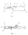
- the device according to the invention has a flexible hollow wire 1, which is formed, for example, by winding three strands 2, 3, 4.
- the hollow wire 4 is passed through a catheter 6.
- the junction point 7 the screw winding of the individual wires 2, 3, 4 is removed and these are guided axially essentially parallel to one another until they are brought together again in a further junction area 8, which is arranged at a distance from the former, and in a screw thread guide to a further section 9 of the hollow wire 1 are formed.
- sleeves 11, 12 can be seated, which prevent the wound areas from being unscrewed.
- a sleeve 14 can also be clamped on the hollow wire 1.
- a pull wire 21 extends freely and axially displaceable through the entire hollow wire 1. That end of the pull wire 21 protruding from the proximal end 13 of the hollow wire extension 9 is provided with an abutment in a ball 22, the diameter of which is at least above the inner diameter of the hollow wire extension 9 lies and preferably corresponds to the outer diameter of the hollow wire extension 9 or the sleeve 14 or larger.
- the ball 22 or a corresponding, if appropriate conical, abutment can be provided with cutting edges which are either formed directly on the ball, by means of applied diamond chips or the like, or else are a film provided with micro-cutting edges; especially in the latter case, the abutment is preferably designed as a cone or cylinder.
- the individual wires 2, 3, 4 which extend freely between the regions 7, 8 are provided with cutting edges 16 at least in the central region of their longitudinal extension A.
- the cutting edges 16 are directed essentially tangentially to the central pull wire 21 or an ellipsoid of revolution formed by the wires 2, 3, 4. They can be formed from one side of each wire, if only one direction of rotation is provided then in the direction of rotation; but they are preferably formed on two sides, so that the device according to the invention can be used with two directions of rotation.
- the cutting edges 16, as seen radially (to the wire 21 or the mentioned rotating body) are as far as possible outside, as shown in FIG. 3.
- the wires 2, 3, 4 of the basket formed by them should not have any cutting edges, but rather can also be made blunt, for example from round wire, as shown in FIG. 3a.
- an atherectomy can be performed by pulling the puller wire 21 in the distal direction from the distal end of the device.
- the free-stretched wires 2 to 4 are axially loaded and their ends are pressed axially against one another, as a result of which the central regions of the wires are pressed outwards.
- the recanalization of a possibly completely closed stenosis can be carried out in a conventional manner known per se.
- the arrangement according to the invention can be advanced up to the stenosis, whereby the pull wire 21 can serve as a guide wire.
- the ball 22 comes to rest against the stenosis under the same tension wire 21 is set in rotation, so that the ball 22 or the like can recanalize the stenosis and can thus create a passage through it itself.
- the whole arrangement including the freely extending wire regions 2 to 4 are pushed through the stenosis, then the widening is carried out and the extension mentioned above is created by pulling the wires 2 to 4 backwards.
- the peeled plaque material is preferably sucked off through the catheter 6, whereby it can be sucked up next to the hollow wire 1, as shown in FIGS. 1 and 2.
- a two-lumen catheter with a secondary lumen can also be used, through which streptokinase or the like can be injected to loosen deposits.
- the catheter 6 has a branch 29 in its distal region 27.
- a hose part 30 is fastened to the branch 29, and its end 37 facing away from the branch 29 can be connected to a suction device via an adapter 28 in order to suction the cut-off deposits through the catheter 6.
- the suction device is a motor-driven, in particular electrical, preferably battery-operated pump, the suction rate of which can be changed, such as being adjustable, controllable or regulatable.
- a tight passage for the wires 1, 21 is provided proximal to the branch 29.
- the seal is preferably designed such that a short, elastic and flexible hose part is arranged in a valve part 61, such as a hemostatic valve, the diameter of which in the unloaded state is such that the hollow wire 1 and also the pull wire 21 with its ball 22 in the unloaded state of the hose part can be inserted freely through it.
- a sleeve extension 62 is threaded.
- a cap 63 with an internal thread sits on this. The cap 63 also presses its end face 64, when it is screwed to the branch 29, axially assembles the piece of hose, as a result of which it bears against the hollow wire 1 and forms a secure, reliable seal.
- the hollow wire 1 can then be pushed axially back and forth under friction.
- a distal end 31 of the hollow wire 1 is axially displaceable in a driven hollow shaft 39 of a drive motor 38, but can be clamped axially and non-rotatably with the shaft, for example via a tensioning device 32.
- the hollow shaft 39 is rotatably driven in the motor part 38. Either it or a further hollow shaft 33 protrudes from the rear end 34 of the motor 38.
- the puller wire 21 extends through the hollow shafts 39, 33 and is connected in a rotationally fixed manner to the shaft 33 via a clamping device 36 (which, as mentioned, can optionally be formed in one piece with the shaft 39).
- the motor 38 is switched on, so that the pull wire 21 (possibly also the hollow wire 1) and in particular the possibly roughened ball 22 connected to the pull wire 21 is spun.
- the ball 22 is then pushed against and through the closure by advancing the motor 38 proximally under its cutting action caused by the rotation until recanalization is achieved.
- the hollow wire 1 with its front hollow wire attachment 9 and the individual wire regions 2 to 4 is then pushed through the channel of the to the proximal side of the stenosis.
- the clamping device 38 can then be released.
- the pull wire 21 is withdrawn, so that a relative displacement of the pull wire 21 to the hollow wire 1 is effected.
- the puller wire 21 takes the hollow wire extension 9 along with the ball 21, as a result of which the individual wires 2, 3 and 4 provided with the cutting edges 16 are pressed radially outward. After reaching a desired radius, the clamping device 36 is fixed again and then the motor 38 is put into operation so that the basket formed by the individual wires 2 to 4 rotates and cuts out a desired hollow cylinder from the stenosis while pulling back the motor 38 and thus the two wires 1 and 21.
- this process can be repeated several times until the desired diameter is exposed in the vessel.
- FIG. 5 A second embodiment is shown in FIG.
- a pliers-like device is arranged, which can be controlled in a known manner for opening and closing the pliers via a wire or the like lying inside the hollow wire 1.
- the pliers have two pliers jaws 19 with cutting edges 16.
- the outer edges of the jaws 19 are ground and they form the outer cutting edges 17, and the front edges of the jaws 19 are ground to form the front edges 18.
- This device is preferably used so that the forceps are advanced through the insertion catheter 6 to the stenosis in the closed state.
- the pliers are set in rotation via the hollow wire 1 and when the hollow wire 1 is pushed forward, the front cutting edges 18 can penetrate the stenosis.
- the pliers are then removed in a known manner, e.g. controlled by the puller wire 21, spread to the desired diameter and retracted with rotation.
- the stenosis is peeled out to the set diameter by the outer cutting edges 17.
- FIG. This is based on a type of "Silverman needle" 60 which has two ends 61 with cutting edges 16.
- the two ends 61 have an internal tension so that they spread as far as it does is made possible in this embodiment by the displaceable sleeve 62.
- the sleeve 62 can be connected, for example, to the hollow wire 1 or be identical, and the needle 60 can be set in rotation via the inner wire, which is otherwise used as the pull wire 21, when the latter is connected to the needle 60 in a rotationally fixed manner.
- the ends 61 expand due to their inherent tension to the desired diameter and, according to the explanations for FIG. 5, a stenosis can be made by means of the cutting edges 16 by rotating the needle 60 and pulling back or forth Needle 60 and sleeve 62 are hollowed out.
- the drive 101 has a housing 102 in which there is an electric motor and an energy source, as well as a battery or an accumulator, which can be inserted into the housing via the opening 104.
- a speed controller for the motor which can be controlled by means of a setting button 106, so that the speed can be set and also changed in desired ranges, for example between 0 and 2000 revolutions per minute or more.
- a display 107 is also provided in the housing, here an LCD display shows when the energy of the energy store is used up and a change is therefore necessary.
- the drive 101 is provided with an on and off switch for switching the rotary drive on and off.
- a bridge 109 is provided on the housing, which at its end facing away from the housing 102 (at 110) has an opening which is open from the top and has undercut lateral grooves 130, opening 120 into the radial flanges on a hollow guide part, such as a suction catheter can be used so that it can be fixed relative to the drive 101 and in particular its housing 102, in particular in the axial direction.
- a hollow guide part such as a suction catheter
- a connection part 110 with a drive shaft 114 projects into the space surrounded by the holding bridge 109 for the catheter and is provided at its free end with a connecting projection 116, such as a male Luer locomotive.
- a device for removing the deposits by rotating this device such as a rotation spiral, can be attached in a rotationally fixed manner via the female Luer part.
- Said device or rotary spiral has a straight shaft over its length corresponding approximately to the length of the hollow guide part or catheter and can have a helical design at its proximal end, that is to say the end facing away from the drive 101, and then a ball with or without cutting edge design or it can also be provided with a radially expandable cup, optionally with cutting edges.
- a slide part 117 On the upper side of the housing there is a slide part 117, with which the shaft 114 is rotatably but axially fixedly connected.
- the shaft 114 is in axial but non-rotatable engagement with an output stub of the motor located in the housing 102.
- the drive shaft 114 carries the Luer locomotive 116 in a rotationally fixed manner at its front end. It also has non-rotatably arranged radial flanges 141, 142 which can be formed, for example, on an attached sleeve 143, such as a brass sleeve soldered to the shaft 114. Between the flanges 141, 142, a C-shaped part 144 engages on the shaft 114 or the sleeve 143 connected to it, while guaranteeing the rotational mobility, which was snapped over the shaft 114 or the sleeve 143 and firmly connected to the slide part, for example with a single-digit design is.
- the shaft 114 projects into a guide sleeve 145, which is rotatably mounted relative to the housing via a bearing 146.
- the output shaft 147 of a motor 148 projects into the sleeve 145 and is connected to it in a rotationally fixed manner by means of transverse bores 149 by means of a pin 150.
- the cross section of the part 114a of the shaft 114 projecting into the guide sleeve 145 and the inner cross section of the guide sleeve 145 are not circular, but have a shape which deviates from the circular shape, for example a flattening, so that the shaft 114 is guided by the guide sleeve 145 driven by the motor 148 can be rotated.
- the shaft 114 is still guided through a bearing 150a, relative to which it is displaceable and rotatable.
- the described configuration ensures on the one hand the rotary drive of the shaft 114 by the motor 148 and on the other hand the axial displacement of the shaft 114 relative to and in the sleeve 145.
- FIG. 10 schematically shows an embodiment for implementing the linear reciprocating motion derived from the rotary drive for the connecting part 114.
- the connecting part 114 is rotatably but axially fixedly connected to a sleeve 151 - similar to that of the mentioned sleeve 143 - for example by radial flanges 152 seated firmly on both sides of the sleeve 151 on the connecting part 114.
- a conventional storage can be formed inside the sleeve 151 between this and the connecting part 114.
- a closed groove which is meandered from one end face of the sleeve and around it further back to the first end face.
- the cam 156 of a further rotary sleeve 157 engages in the groove. So that the sleeve 151 does not rotate when the sleeve 157 rotates, it is guided via a cam 161 in a groove 162 in the wall 163 of the housing 102 or in a part firmly connected thereto. When the sleeve 157 rotates, the cam 156 pushes against the wall of the groove 153 of the sleeve 151, which is inclined with respect to its direction of rotation.
- the sleeve 151 takes the connecting part 114 with it when it moves back and forth.
- the rotary drive of the rotary sleeve 157 can be derived from the rotary drive of the motor, namely because the reciprocating movement of the sleeve 151 and thus the rotary movement of the sleeve 157 should be significantly less than the rotary movement of the motor via a reduction gear, for example in the form of a sun gear Planetary gears can be designed with an internal gear formed in the sleeve 157, in the form of clockwork gears or the like.
- the shaft 114 and thus the connecting part 110 are driven directly in the same manner as was described with reference to FIG. 9.
Abstract
Description
Die Erfindung betrifft eine Vorrichtung nach dem Oberbegriff des Anspruchs 1.The invention relates to a device according to the preamble of
Es ist eine derartige Vorrichtung zur Atherektomie bekannt, die an dem proximalen Ende einer als schraubenförmig gewickelter Draht ausgebildeten Antriebswelle zwei konisch aufeinander zu gerichtete Schneidmesser aufweist. Im Hinblick auf eine nicht eindeutige Terminologie hinsichtlich der Bezeichnung proximal und distal wird in der vorliegenden Anmeldung unter Berücksichtigung, daß rumpfwärts bzw. zum Herzen hin gelegene Teile einer Extremität durchgängig als "proximale" bezeichnet werden, das zum Herzen hin gelegene Ende der erfindungsgemäßen Vorrichtung bzw. eines Teils derselben als proximal und der zum Operateur hin gerichtete Teil als distaler bezeichnet.Such a device for atherectomy is known, which has two conical cutting knives directed towards one another at the proximal end of a drive shaft designed as a helically wound wire. With regard to an ambiguous terminology with respect to the designation proximal and distal, the present application takes into account that parts of an extremity located towards the trunk or towards the heart are referred to as "proximal" throughout, the end of the device according to the invention or towards the heart towards the heart part of the same is referred to as proximal and the part directed towards the surgeon as distal.
Bei der bekannten Vorrichtung hat der distale Bereich der Schneiden aufgrund der zum proximalen Ende hin konischen Zurichtung einen erheblichen Durchmesser, wobei auch die Welle einen entsprechenden Durchmesser hat. Da die Welle durch einen Katheter geführt werden muß, muß dieser einen entsprechend noch größeren Durchmesser haben. Der durch die bekannte Vorrichtung zu schaffende Kanal durch eine Stenose oder einen Verschluß in einem Gefäß bestimmt daher die Größe der Punktionsstelle zum Einführen der Vorrichtung, die einen wesentlich größeren Querschnitt aufweisen muß als der im Gefäß freizulegende Kanal. Die durch Schraubenwicklung eines Drahtes gebildete Welle läßt sich aufgrund ihrer Stärke schlecht abdichten, so daß Blut aus dem Gefäß und distal aus der Vorrichtung austreten kann. Bei stärkerer Festklemmung eines Abdichtventils erhöht sich die Reibung derart, daß eine Beschädigung der Antriebswelle eintreten kann.In the known device, the distal area of the cutting edges has a considerable diameter due to the conical dressing towards the proximal end, whereby also the Shaft has a corresponding diameter. Since the shaft has to be passed through a catheter, it must have a correspondingly larger diameter. The channel to be created by the known device through a stenosis or a closure in a vessel therefore determines the size of the puncture site for inserting the device, which must have a substantially larger cross section than the channel to be exposed in the vessel. The shaft formed by the screw winding of a wire is difficult to seal due to its strength, so that blood can escape from the vessel and distally from the device. If a sealing valve is stuck more tightly, the friction increases such that damage to the drive shaft can occur.
Weiterhin können Ablagerungen, wie thrombotische Okklusionen in Gefäßen oder dergleichen, durch ein in das Gefäß zum Verschluß beziehungsweise der Verengung hin geführtes drehbares Element abgetragen werden, wobei einerseits vorgeschlagen wird, eine Rotation im Bereich von 100.000 Umdrehungen pro Minute zu verwenden, um das Okklusionsmaterial zu pulverisieren. Es besteht die Gefahr, daß die pulverisierten Teilchen sich wieder an anderen Stellen, möglicherweise in wesentlich engeren, aber wichtigen Gefäßen, ablagern und dort zu Schädigungen führen können. Andere, mit geringer Drehzahl bis höchstens 500 Umdrehungen pro Minute umlaufende Vorrichtungen beschränken sich darauf, das gefäßverschließende Material zur Seite zu drängen. Hiermit kann keine zuverlässige dauerhafte Freilegung einer Stenose erreicht werden, von einer Öffnung einer Okklusion ganz zu schweigen. Es sind weiterhin Vorrichtungen bekannt, die verengendes Material im Gefäß in der einen oder anderen Form herausschneiden. Soweit hier ein drehender Katheter eingesetzt wird, so besteht die Gefahr, daß dieser bei seiner Drehung die Gefäßwand mitnimmt und so eine Verschlingung zu verursachen droht, so daß auch hier nur mit sehr geringen Geschwindigkeiten gearbeitet werden kann. Soweit das Abtragen durch an einer Welle durch einen Katheter geführte Arbeitswerkzeuge geschieht, so müssen diese mit Abstand zur Kathetermündung arbeiten, so daß gegebenenfalls durch den Katheter ausgeübter Sog zur Entfernung der abgetragenen Partikel nicht ausreicht, sämtliche Partikel mitzuziehen.Deposits, such as thrombotic occlusions in vessels or the like, can also be removed by means of a rotatable element guided into the vessel for closure or narrowing, whereby on the one hand it is proposed to use a rotation in the range of 100,000 revolutions per minute in order to close the occlusion material pulverize. There is a risk that the powdered particles will deposit again in other places, possibly in much narrower but important vessels, and can cause damage there. Other devices rotating at low speed up to a maximum of 500 revolutions per minute are limited to pushing the vaso-occlusive material aside. A reliable permanent exposure of a stenosis cannot be achieved with this, not to mention the opening of an occlusion. Devices are also known which cut out constricting material in the vessel in one form or another. Insofar as a rotating catheter is used here there is a risk that this will take the vessel wall with it when it rotates and thus threatens to cause entanglement, so that here too, work can only be carried out at very low speeds. Insofar as the removal is carried out by working tools guided on a shaft by a catheter, these must work at a distance from the mouth of the catheter, so that suction, if any, exerted by the catheter is not sufficient to remove all the removed particles.
Die US-A-4 679 557 zeigt eine Vorrichtung zur Atherektomie mit einem Katheter mit einem hindurchgeführten länglichen Teil aus einem drehbaren Hohlelement und einem sich durch dieses hindurch erstreckenden Zugdraht, wobei am proximalen Ende des Hohlelements ein Arbeitselement angebracht ist. Das Hohlelement ist an seinem distalen Ende zum Drehantrieb des mit ihm verbundenen spreizbaren Elements mit einem motorischen Drehantrieb versehbar, und der Katheter ist in seinem distalen Endbereich mit einer Absaugeinrichtung verbindbar, mittels der Ablagerungen durch den Katheter hindurch absaugbar sind, die mittels des spreizbaren Elements von einer Gefäßwandung entfernt wurden (siehe Beschreibung, Spalte 1, Zeile 61-67). Die Verbindung von Hohl- und Arbeitselement ist eine Schwachstelle: es besteht die Gefahr, daS sie sich löst, wodurch das Arbeitselement vom Hohlelement getrennt wird. Dies ist für den Patienten höchst gefährlich.US-A-4 679 557 shows a device for atherectomy with a catheter with an elongated part made of a rotatable hollow element and a pulling wire extending therethrough, a working element being attached to the proximal end of the hollow element. The hollow element can be provided with a motorized rotary drive at its distal end for the rotary drive of the expandable element connected to it, and the catheter can be connected in its distal end region to a suction device by means of which deposits can be suctioned through the catheter, which by means of the expandable element of a vessel wall have been removed (see description,
Der Erfindung liegt daher die Aufgabe zugrunde, unter Vermeidung der vorgenannten Nachteile bei einer Atherektomie-Vorrichtung die Betätigung des Arbeitselements zu verbessern.The invention is therefore based on the object of improving the actuation of the working element while avoiding the aforementioned disadvantages in an atherectomy device.
Erfindungsgemäß wird die genannte Aufgabe durch eine Atherektomie-Vorrichtung nach dem Oberbegriff des Anspruchs 1 gelöst, welche die kennzeichnenden Merkmale des Anspruchs 1 aufweist. In bevorzugter Weise kann vorgesehen sein, daß die Schneide(n) sich in der achsnahen Stellung im wesentlichen axial erstreckt (erstrecken).According to the invention, the stated object is achieved by an atherectomy device according to the preamble of
Durch die Vorsehung von radial spreizbaren Elementen zum Abtragen der Beläge etc. wird es ermöglicht, diese zunächst in ihrer kontrahierten Stellung in das Gefäß einzuführen, so daß eine Punktion mit einem geringen Querschnitt notwendig ist. Andererseits können die Elemente am Operationsort radial gespreizt werden, so daß mit ihnen eine Atherektomie mit einem im Gefäß freigelegten Kanal durchgeführt werden kann, der einen wesentlich größeren Querschnitt als die notwendige Punktionsstelle aufweist. Hierdurch wird die Belastung des Patienten reduziert. Weiterhin wird das Arbeiten mit einer erfindungsgemäßen Vorrichtung erleichtert.The provision of radially spreadable elements for removing the coverings etc. makes it possible to first insert them into the vessel in their contracted position, so that a puncture with a small cross-section is necessary. On the other hand, the elements can be spread radially at the surgical site, so that they can be used to perform an atherectomy with a channel exposed in the vessel, which has a substantially larger cross-section than the necessary puncture site. This reduces the burden on the patient. Furthermore, working with a device according to the invention is made easier.
Grundsätzlich können die Elemente durch ein Spreizelement nach außen in ihre Schneid- bzw. Betriebsstellung gestellt werden. Nach einer solchen Ausgestaltung wird der Erweiterungsvorgang der Gefäßverengung auf jeden Fall von deren proximalem Ende her durchgeführt, wobei die Elemente zunächst in kontrahierter Vorrichtung durch einen in herkömmlicher Weise ausgebildeten Kanal dorthin bewegt wurden, bevor sie radial gespreizt werden. Grundsätzlich das gleiche Vorgehen kann auch vorgenommen werden, ist aber nicht notwendig, bei einer Ausgestaltung, bei der Endbereiche der Elemente axial aufeinander zu bewegbar sind. Bei der Ausgestaltung sind die Elemente elastisch flexibel ausgebildet und werden radial dadurch gespreizt, daß mit Axialabstand auf jeweils einem Element liegende Punkte axial aufeinander zu bewegt werden, wodurch die vorzugsweise drahtförmigen Elemente radial nach außen gebogen werden. Diese Ausgestaltung weist den Vorteil auf, daß keine sich nach außen erstreckenden freien Stirnseiten oder Enden der Elemente vorhanden sind. Während die Schneidelemente grundsätzlich aus Stahldraht bestehen können, sind sie insbesondere bei der vorbeschriebenen Ausgestaltung aus Nickeltitanlegierung, wie aus Nitinol, die gegenüber Stahldraht eine höhere Flexibilität aufweist. Es wird vorzugsweise Flachdraht verwendet, an dem die Schneiden geschliffen sind.In principle, the elements can be moved outwards into their cutting or operating position by means of an expansion element. According to such a configuration, the enlargement process of the vasoconstriction is carried out in any case from its proximal end, the elements first being moved there in a contracted device by a channel designed in a conventional manner before they are spread radially. Basically, the same procedure can also be carried out, but is not necessary in a configuration in which end regions of the elements can be moved axially towards one another. In the configuration, the elements are designed to be elastically flexible and are spread radially by lying on one element at an axial distance Points are moved axially towards one another, as a result of which the preferably wire-shaped elements are bent radially outward. This configuration has the advantage that there are no free end faces or ends of the elements which extend outwards. While the cutting elements can basically consist of steel wire, they are, in particular in the case of the configuration described above, made of nickel-titanium alloy, such as Nitinol, which has a greater flexibility than steel wire. Flat wire is preferably used, on which the cutting edges are ground.
Die axiale Spannung der Elemente wird in der bevorzugten Ausgestaltung dadurch erreicht, daß die Elemente an Tragteilen ausgebildet sind, die an den mit Abstand zueinander angeordneten Verbindungsstellen zusammengehalten sind und daß die Verbindungsstellen axial aufeinander zu bewegbar sind. Die Elemente weisen vorzugsweise auf einem Teilbereich der Drahtteile durch Zuschleifen ausgebildete Schneiden oder Messer auf. Die Schneiden weisen dabei im wesentlichen in tangentiale Richtung eines durch die Drahtteile gebildeten Rotationskörpers. Das Spannen kann in konkreter Weise dadurch geschehen, daß der Zugdraht durch die Verbindungsstellen geführt ist und mittels ihm die Verbindungsstellen zueinander hinziehbar sind, wobei weiterhin vorgesehen sein kann, daß die Drahtteile im Bereich der Verbindungsstellen durch Hülsen zusammengehalten sind.The axial tension of the elements is achieved in the preferred embodiment in that the elements are formed on support parts which are held together at the spaced-apart connection points and that the connection points are axially movable towards one another. The elements preferably have cutting edges or knives formed on a partial area of the wire parts by grinding. The cutting edges point essentially in the tangential direction of a rotating body formed by the wire parts. The tensioning can take place in a concrete manner in that the pull wire is guided through the connection points and by means of it the connection points can be drawn towards one another, it also being possible for the wire parts to be held together by sleeves in the area of the connection points.
Eine weitere Ausbildung sieht vor, daß sich an die Elemente bzw. Drahtstücke proximal ein schraubenförmig gewickelter Hohldrahtansatz anschließt, wobei der distal ausgebildete Hohldraht eine Antriebswelle zum Drehantreiben der Schneiden bildet.A further embodiment provides that the elements or wire pieces are connected proximally to a helically wound hollow wire attachment, the hollow wire formed distally forming a drive shaft for rotating the cutting edges.
Der proximal zu den Elementen angeordnete Hohldrahtansatz trägt dazu bei, vor der Aufweitung des Gefäßlumens eine Rekanalisation zu schaffen, um den Aufweit- und Abtragvorgang durch die Elemente vom proximalen Ende der Verengung her vornehmen zu können.The hollow wire attachment arranged proximal to the elements helps to create a recanalization before the expansion of the vessel lumen in order to be able to carry out the expansion and removal process through the elements from the proximal end of the constriction.
Wenn gemäß weiterer bevorzugter Ausgestaltung vorgesehen ist, daß der Zugdraht die Elemente bzw. Einzeldrähte proximal überragt und an seinem überragenden Ende ein erweitertes Widerlager gegen eine distal ausgeübte Zugkraft befestigt ist und daß das Widerlager als Kugel ausgebildet ist, so kann durch Ziehen am Zugdraht in distaler Richtung über das Widerlager die Zugkraft auf den proximalen Zusammenführungs- bzw. Verbindungsbereich der gegebenenfalls Schneiden tragenden Einzeldrähte übertragen werden, so daß dieser Verbindungsbereich in dieser Weise zum distalen Verbindungsbereich der Einzeldrähte gezogen werden kann, wodurch diese sich - gegebenenfalls mit ihren Schneiden - radial nach außen stellen.If, according to a further preferred embodiment, it is provided that the pull wire extends beyond the elements or individual wires proximally and an extended abutment is attached to a distal tensile force at its projecting end, and that the abutment is designed as a ball, then pulling the pull wire in a distal direction Direction via the abutment, the tensile force is transmitted to the proximal merging or connecting area of the individual wires, which may have cutting edges, so that this connecting area can be pulled in this way to the distal connecting area of the individual wires, causing them to extend radially outward, if necessary with their cutting edges put.
Während die Rekanalisation grundsätzlich in bekannter Weise durchgeführt werden kann, sieht eine bevorzugte Ausgestaltung vor, daß die erfindungsgemäße Vorrichtung hierzu eingesetzt werden kann, so daß vermieden wird, daß verschiedene Instrumente durch den Führungskatheter wiederholt ein- und ausgebracht werden müssen. Hierzu ist die am sich durch den proximalen Hohldrahtabschnitt hindurch erstreckenden Zugdraht ausgebildete Kugel oder allgemein ein Widerlager mit Schneidteilen versehen. Solche Schneidteile können durch auf der Kugel angebrachte Diamantsplitter, durch an dieser ausgefräste Schneiden oder auf dieser befestigte Schneidfolie gebildet sein.While the recanalization can in principle be carried out in a known manner, a preferred embodiment provides that the device according to the invention can be used for this purpose, so that it is avoided that different instruments have to be repeatedly inserted and removed through the guide catheter. For this purpose, the ball or generally an abutment formed on the pull wire extending through the proximal hollow wire section is provided with cutting parts. Such cutting parts can be formed by diamond chips attached to the ball, by cutting milled on the ball, or by cutting film attached to the ball.
In weiterer Ausgestaltung kann insbesondere vorgesehen sein, daß der Zugdraht als Hohldraht ausgebildet ist und sich dessen Hohlraum gegebenenfalls durch das Widerlager hindurch erstreckt. Bei einer solchen Ausgestaltung kann zunächst in völlig üblicher Weise ein herkömmlicher Führungsdraht gelegt werden, über den dann die erfindungsgemäße Vorrichtung eingeführt wird. Hierdurch wird neben einem antegraden Ausschälen des Gefäßes insbesondere ein retrogrades Freilegen unterstützt.In a further embodiment, it can be provided in particular that the pull wire is designed as a hollow wire and its cavity may extend through the abutment. With such a configuration, a conventional guide wire can be placed in a completely customary manner, through which the device according to the invention is then introduced. In addition to antegrade peeling of the vessel, this supports in particular a retrograde exposure.
In einer anderen Ausgestaltung ist vorgesehen, daß die Vorrichtung bzw. die spreizbaren Elemente zangenartig ausgebildet ist. Dabei ergibt sich eine besonders einfache Realisierung, wenn die Schneiden angeschliffene Axialkanten der Zangenbacken sind.In another embodiment it is provided that the device or the expandable elements are designed like pliers. This results in a particularly simple implementation if the cutting edges are ground axial edges of the pliers jaws.
Um abgetragene Elemente zur Kathetermündung zu bewegen, damit diese von dort anliegendem Unterdruck zuverlässig abgesaugt werden können, weist die Vorrichtung weiterhin ein drehbares Anschlußteil zum Drehantrieb der spreizbaren Elemente auf.In order to move worn elements to the catheter mouth so that they can be reliably suctioned off from the negative pressure present there, the device also has a rotatable connecting part for rotating the expandable elements.
Durch die axial bewegliche Ausgestaltung des durch den Antrieb gedrehten Anschlußteils desselben für die die Ablagerung abtragenden Arbeitswerkzeuge (die in unterschiedlichster Weise ausgestaltet sein können) wird es möglich, die Arbeitswerkzeuge einerseits zum Abtragen des zu entfernenden Materials aus der Kathetermündung heraus in den Bereich der Stenose oder Okklusion einzuführen und andererseits rhythmisch die Arbeitswerkzeuge unter Aufrechterhaltung der Arbeitsdrehung zur Kathetermündung und gegebenenfalls teilweise in diese hinein zurückzubringen, so daß mit den Arbeitswerkzeugen mitgeführte Partikel zuverlässig durch den im Katheter oder im hohlen Führungsteil ausgeübten Unterdruck abgesaugt werden können.Due to the axially movable design of the connecting part rotated by the drive for the working tools that remove the deposit (which can be designed in various ways), it becomes possible, on the one hand, to remove the material to be removed from the catheter mouth into the area of the stenosis or Introduce occlusion and, on the other hand, rhythmically bring back the work tools while maintaining the work rotation to the catheter mouth and possibly partially into it, so that particles carried along with the work tools can be reliably sucked off by the negative pressure exerted in the catheter or in the hollow guide part.
Die durch den Antrieb getriebenen Arbeitswerkzeuge können in unterschiedlicher Weise ausgebildet sein. Es können spiralförmige Ausbildungen oder Körbchenausbildungen sein, bei denen also Abtragungselemente in Form von Drähten - stumpf oder zugeschliffen - in Axialrichtung auf dem Umfang eines fiktiven Rotationsellipsoiden angeordnet sind. Diese beiden Ausgestaltungen fangen in dem durch die Abtragungsdrähte beziehungsweise die Schrauben- oder Wendelausbildung gegebenen Bereich abgetragenes Material und können dieses daher bei ihrer Zurückbewegung zur Mündung des hohlen Führungsteils hin zuverlässig mitnehmen, so daß das abgetragene Material zuverlässig abgesaugt wird. Grundsätzlich sind aber auch andere Ausgestaltungen der Werkzeuge möglich.The work tools driven by the drive can be designed in different ways. It can be spiral-shaped or cup-shaped, in which removal elements in the form of wires - blunt or ground - are arranged in the axial direction on the circumference of a fictitious rotation ellipsoid. These two configurations catch the material removed by the removal wires or the screw or helix formation and can therefore reliably take it with them when they move back towards the mouth of the hollow guide part, so that the removed material is reliably extracted. In principle, however, other configurations of the tools are also possible.
Die axiale Hin- und Herbewegung des Anschlußteils des erfindungsgemäßen Antriebs und damit der mit diesem verbundenen Arbeitswerkzeuge erfolgt in einer bevorzugten Ausgestaltung manuell, wobei vorteilhafterweise vorgesehen ist, daß das drehbare Anschlußteil manuell axial hin- und herbewegbar ist. Hierdurch kann der Operateur die axiale Hin- und Herbewegung der Arbeitswerkzeuge in gewünschter Weise steuern und einstellen. Zur Erleichterung und Entlastung des Operateurs kann in alternativer Weise auch vorgesehen sein, daß das drehbare Anschlußteil motorisch axial hin- und herbewegbar ist. Der Axialantrieb kann dabei derart ausgebildet sein, daß eine axial fest, aber drehbar mit dem Anschlußteil und drehfest mit dem Gehäuse des Antriebs verbundene Hülse mit einer geschlossenen, in Form eines Meanders um den Umfang geführten Nut, in der die Nocken eines mit gegenüber der Winkelgeschwindigkeit des Anschlußteils geringer Winkelgeschwindigkeit umlaufenden Übertragungsteils eingreift. Die Hin- und Herbewegung kann von dem gleichen Motor abgeleitet sein, der die hochtourige Drehbewegung im Bereich von wenigen 100 bis 2000 Umdrehungen pro Minute des Anschlußteils und damit der Arbeitswerkzeuge bewirkt, indem zwischen der Abtriebswelle des Motors und dem Umsetzgetriebe zur Umsetzung eines Drehantriebs in die lineare Hin- und Herbewegung ein Übersetzungsgetriebe angeordnet ist, wie es beispielsweise grundsätzlich aus Uhrwerken bekannt ist.The axial back and forth movement of the connecting part of the drive according to the invention and thus of the working tools connected to it takes place manually in a preferred embodiment, it being advantageously provided that the rotatable connecting part can be moved axially back and forth manually. This enables the operator to control and adjust the axial back and forth movement of the work tools in the desired manner. To facilitate and relieve the surgeon, it can alternatively be provided that the rotatable connecting part can be moved axially back and forth by motor. The axial drive can be designed such that an axially fixed, but rotatably connected to the connecting part and rotatably connected to the housing of the drive sleeve with a closed, in the form of a meandering around the circumference, in which the cams one with respect to the angular velocity of the connecting part engaging low angular velocity rotating transmission part. The back and forth movement can be derived from the same motor, which causes the high-speed rotary movement in the range of a few 100 to 2000 revolutions per minute of the connecting part and thus of the working tools, between the output shaft of the motor and the conversion gear for converting a rotary drive into the linear reciprocating a transmission gear is arranged, as is known for example in principle from clockworks.
Zum Anschluß der Arbeitswerkzeuge beziehungsweise derselben über eine durch das Führungsteil hindurchragenden Welle kann das Anschlußteil ein Kopplungselement beispielsweise in Form eines Luer-Loks oder dergleichen aufweisen. Das hohle längliche Führungsteil, insbesondere ein Katheter wird mit dem Antrieb fest dadurch verbunden, indem an der Aufnahmeeinrichtung für diesen eine in axialer Richtung beidseitig durch Schultern begrenzte nach innen gerichtete Umfangsnut ausgebildet ist, in die radial Flanschteile des Katheters oder mit diesem fest verbundene Elemente eingesetzt werden können.To connect the working tools or the same via a shaft protruding through the guide part, the connecting part can have a coupling element, for example in the form of a Luer locomotive or the like. The hollow elongated guide part, in particular a catheter, is firmly connected to the drive by forming an inward circumferential groove on the receiving device for it, which is delimited in the axial direction on both sides by shoulders, into the radial flange parts of the catheter or elements firmly connected to it can be.
Der Antrieb weist vorzugsweise einen Elektromotor auf und ist, um einerseits eine Unabhängigkeit vom Stromnetz zu gewährleisten, andererseits aus sicherheitstechnischen Gründen mit einem eigenen Energiespeicher versehen. Dieser kann ein aufladbarer Akkumulator oder aber eine Batterie sein. In beiden Fällen ist es vorteilhaft, weiterhin vorzusehen, daß die Anzeigeeinrichtung eine LCD-Anzeige ist. Hierdurch wird der Operateur rechtzeitig auf mangelnden Energievorrat des Energiespeichers und Abfall der Spannung hingewiesen, so daß er während einer Operation hiervon nicht überrascht wird, sondern rechtzeitig vorher den Energiespeicher austauschen kann. Vorzugsweise ist auch der Akkumulator auswechselbar in einem entsprechenden Fach im Gehäuse angeordnet. Eine weitere bevorzugte Ausgestaltung sieht vor, daß der Antrieb mit einem Geschwindigkeitsregler versehen ist. Weiterhin weist er selbstverständlich einen Ein- und Ausschalter auf.The drive preferably has an electric motor and, on the one hand, to ensure independence from the power supply and, on the other hand, is provided with its own energy store for safety reasons. This can be a rechargeable battery or a battery. In both cases, it is advantageous to further provide that the display device is an LCD display. As a result, the surgeon is informed in good time of a lack of energy in the energy store and a drop in the voltage, so that he is not surprised during an operation, but can replace the energy store in good time. The accumulator is preferably also interchangeably arranged in a corresponding compartment in the housing. Another preferred embodiment provides that the drive is provided with a speed controller. Furthermore, it naturally has an on and off switch.
Weitere Vorteile und Merkmale der Erfindung ergeben sich aus den Ansprüchen und aus der nachfolgenden Beschreibung, in der zwei Ausführungsbeispiele der Erfindung unter Bezugnahme auf die Zeichnung im einzelnen erläutert ist. Dabei zeigt:
Figur 1- eine Seitenansicht, teilweise geschnitten, des Schneidbereichs der erfindungsgemäßen Vorrichtung in Einführungszustand;
Figur 2- den
Gegenstand der Figur 1 im Arbeitszustand; Figur 3- einen Schnitt entsprechend III-
III der Figur 2; - Figur 3a
- einen Schnitt entsprechend der Figur 3 mit stumpfen Körbchendrähten;
Figur 4- eine Gesamtdarstellung der erfindungsgemäßen Vorrichtung mit Antriebsteil;
- Figur 5
- eine zangenartige Ausbildung einer erfindungsgemäßen Vorrichtung;
Figur 6- ein weiteres Ausführungsbeispiel.
Figur 7- eine Seitenansicht des erfindungsgemäßen Antriebs;
Figur 8- eine Draufsicht auf den Antrieb entsprechend dem Teil II der
Figur 1; und Figur 9- eine bevorzugte Ausführungsform der Kopplung des Linearantriebs mit dem mitteltourigen Drehantrieb.
Figur 10- die schematische Darstellung eines Ausführungsbeispiels für einen motorischen hin- und hergehenden Linearantrieb des Anschlußteils
- Figure 1
- a side view, partially in section, of the cutting area of the device according to the invention in the inserted state;
- Figure 2
- the object of Figure 1 in the working state;
- Figure 3
- a section corresponding to III-III of Figure 2;
- Figure 3a
- a section corresponding to Figure 3 with blunt cup wires;
- Figure 4
- an overall view of the device according to the invention with drive part;
- Figure 5
- a plier-like design of a device according to the invention;
- Figure 6
- another embodiment.
- Figure 7
- a side view of the drive according to the invention;
- Figure 8
- a plan view of the drive corresponding to Part II of Figure 1; and
- Figure 9
- a preferred embodiment of the coupling of the linear drive with the medium-speed rotary drive.
- Figure 10
- the schematic representation of an embodiment for a motorized reciprocating linear drive of the connecting part
Die erfindungsgemäße Vorrichtung weist in der dargestellten Ausführungsform einen flexiblen Hohldraht 1 auf, der beispielsweise durch Wendeln von drei Litzen 2, 3, 4, gebildet ist. Der Hohldraht 4 ist durch einen Katheter 6 geführt. In einem als Zusammenführungsstelle 7 bezeichneten Bereich ist die Schraubenwicklung der Einzeldrähte 2, 3, 4 aufgehoben und diese sind im wesentlichen parallel zueinander axial geführt, bis sie in einem weiteren Zusammenführungsbereich 8, der mit Abstand zu dem erstgenannten angeordnet ist, wieder zusammengeführt und in Schraubgewindeführung zu einen weiteren Abschnitt 9 des Hohldrahtes 1 gebildet sind. An den Zusammenführungsstellen 7, 8 können Hülsen 11, 12 aufsitzen, die ein Aufdrehen der gewickelten Bereiche verhindern. Am proximalen Ende 13 kann ebenfalls eine Hülse 14 auf dem Hohldraht 1 aufgeklemmt sein.In the embodiment shown, the device according to the invention has a flexible
Durch den gesamten Hohldraht 1 erstreckt sich frei und axial zu diesem verschiebbar ein Zugdraht 21. Daß aus dem proximalen Ende 13 des Hohldrahtansatzes 9 herausragende Ende des Zugdrahts 21 ist mit einem Widerlager in einer Kugel 22 versehen, deren Durchmesser zumindestens über dem Innendurchmesser des Hohldrahtansatzes 9 liegt und vorzugsweise dem Außendurchmesser des Hohldrahtansatzes 9 bzw. der Hülse 14 entspricht oder größer ist. Die Kugel 22 oder ein entsprechendes gegebenenfalls konisch ausgebildetes Widerlager kann mit Schneidkanten versehen sein, die entweder direkt an der Kugel ausgebildet sind, durch aufgebrachte Diamantsplitter oder dergleichen oder aber eine mit Mikroschneidkanten versehene Folie sind; insbesondere im letzteren Fall ist das Widerlager vorzugsweise als Kegel oder auch Zylinder ausgebildet.A
Die sich zwischen den Bereichen 7, 8 frei erstreckenden Einzeldrähte 2, 3, 4 sind zumindestens im Mittelbereich ihrer Längserstreckung A mit Schneiden 16 versehen. Die Schneiden 16 sind dabei im wesentlichen tangential zum zentralen Zugdraht 21 bzw. einen durch die Drähte 2, 3, 4 gebildeten Rotationsellipsoid gerichtet. Sie können dabei von einer Seite jedes Drahtes ausgebildet sein und zwar wenn nur eine Drehrichtung vorgesehen ist dann in Drehrichtung; vorzugsweise sind sie aber an zwei Seiten ausgebildet, so daß die erfindungsgemäße Vorrichtung mit zwei Drehrichtungen eingesetzt werden kann. Weiterhin liegen die Schneidkanten 16 radial gesehen (zum Draht 21 bzw. dem erwähnten Rotationskörper) möglichst außerhalb, wie dies in der Figur 3 dargestellt ist. Alternativ müßten die Drähte 2, 3, 4 des der durch sie gebildeten Körbchens keine Schneidkanten aufweisen, können vielmehr auch stumpf, beispielsweise aus Runddraht ausgebildet sein, wie dies in der Figur 3a dargestellt ist.The
Wenn nun die Drähte 2 bis 4 mit ihren Schneidkantenbereichen 16 in der aus Figur 1 ersichtlichen unbelasteten Stellung, bei denen sie nur eine geringe Querschnittsfläche umschließen durch den Katheder 6 in den Bereich einer Stenose eines Gefäßes, gegebenenfalls nach Rekanalisation eingebracht wurde, so kann eine Atherektomie vorgenommen werden, indem der Zugdraht 21 vom distalen Ende der Vorrichtung her in distale Richtung gezogen wird. Hierzu werden die freigespannten Drähte 2 bis 4 axial belastet und ihre Enden axial gegeneinandergedrückt, wodurch die Mittelbereiche der Drähte nach außen gedrückt werden. Durch Rotation der Drähte 2 bis 4, gegebenenfalls durch einen am distalen Ende des Hohldrahtes 1 angreifenden motorischen - vorzugsweise batterie- oder akkubetriebenen - Antrieb können durch die Schneidkanten 16 Ablagerungen im Bereich der Stenose abgetragen werden und derart das Gefäß wieder weitgehend freigelegt werden, indem der Radius des durch die Drähte 2 bis 4 gebildeten Rotationsellipsoids stufenweise oder kontinuierlich bis zu dem gewünschten Umfang erweitert wird. Insbesondere kann eine Freilegung bis zu einem Querschnitt erreicht werden, der über dem Querschnitt des Einführungskatheters 6 liegt. Weiterhin wird durch die erfindungsgemäße Vorrichtung erreicht, daß trotz sehr kleiner Funktionstellen im Bereich von fünf Charrière oder "French" (5/3 ≈ ca. 1,7 mm) Gefäße bis zu einem Durchmesser von über zehn Charrière, teilweise bis zu 8 mm freigelegt werden können.If the
Die Rekanalisation einer gegebenenfalls vollständig geschlossenen Stenose kann in herkömmlich und an sich bekannter Weise erfolgen. Stattdessen kann, wenn das Teil 22, wie eine Kugel mit Schneidelementen versehen ist, die erfindungsgemäße Anordnung bis vor die Stenose vorgeschoben werden, wobei der Zugdraht 21 als Führungsdraht dienen kann. Auf jeden Fall wird, sobald die Kugel 22 unter der gleichen an der Stenose zur Anlage kommt der Zugdraht 21 in Rotation versetzt, so daß die Kugel 22 oder dergleichen die Stenose rekanalisieren kann und sich daher derart selbst einen Durchgang durch diese schaffen kann. Vorzugsweise wird die ganze Anordnung einschließlich der sich frei erstreckenden Drahtbereiche 2 bis 4 durch die Stenose hindurchgeschoben, anschließend die Aufweitung vorgenommen und durch Rückwärtsziehen der Drähte 2 bis 4 die oben erwähnte Erweiterung geschaffen.The recanalization of a possibly completely closed stenosis can be carried out in a conventional manner known per se. Instead, if the
Das abgeschälte Plaque-Material wird vorzugsweise durch den Katheter 6 abgesaugt, wobei es, wie er in der Figuren 1 und 2 dargestellt ist, neben dem Hohldraht 1 abgesaugt werden kann. Grundsätzlich kann auch ein zweilumiger Katheter mit einem Nebenlumen verwendet werden, durch welches Streptokinase oder dergleichen zum Anlösen von Ablagerungen eingespritzt werden kann.The peeled plaque material is preferably sucked off through the
Eine Katheteranordnung 6, wie sie im Rahmen der Erfindung eingesetzt werden kann, ist in der Figur 4 dargestellt. Der Katheter 6 weist in seinem distalen Bereich 27 einen Abzweig 29 auf. An dem Abzweig 29 ist ein Schlauchteil 30 befestigt, das mit seinem dem Abzweig 29 abgewandten Ende 37 über einen Adapter 28 mit einer Absaugeinrichtung verbindbar ist, um die abgeschnittenen Ablagerungen durch den Katheter 6 abzusaugen. In bevorzugter Ausgestaltung ist die Absaugeinrichtung eine motorisch, insbesondere elektrisch, vorzugsweise batteriebetriebene Pumpe, deren Absaugrate veränderbar, wie einstellbar, steuerbar oder regelbar ist.A
Proximal des Abzweigs 29 ist ein dichter Durchlaß für die Drähte 1, 21 vorgesehen. Die Dichtung ist dabei vorzugsweise derart ausgebildet, daß in einem Ventilteil 61, wie eines hämostatischen Ventils, ein kurzes, elastisches und flexibles Schlauchteil angeordnet ist, dessen Durchmesser im unbelasteten Zustand derart ist, daß der Hohldraht 1 und auch der Zugdraht 21 mit seiner Kugel 22 im unbelasteten Zustand des Schlauchteils durch dieses frei hindurchgesteckt werden kann. Ein Hülsenansatz 62 ist mit einem Gewinde versehen. Auf diesem sitzt eine mit einem Innengewinde versehene Kappe 63 auf. Die Kappe 63 drückt mit ihrer Stirnseite 64, wenn sie zum Abzweig 29 hingeschraubt wird, das Schlauchstück axial zusammen, wodurch dieses sich am Hohldraht 1 anlegt und eine sichere, zuverlässige Abdichtung bildet. Der Hohldraht 1 kann dann weiterhin unter Reibung axial vor- und zurückgeschoben werden.A tight passage for the
Ein distales Ende 31 des Hohldrahtes 1 ist in einer angetriebene Hohlwelle 39 eines Antriebsmotors 38 axial verschiebbar, kann aber mit der Welle axial- und drehfest verspannt werden, beispielsweise über eine Verspanneinrichtung 32. Die Hohlwelle 39 ist im Motorteil 38 drehantreibbar gelagert. Entweder sie oder eine weitere Hohlwelle 33 ragt am rückwärtigen Ende 34 des Motors 38 aus diesem heraus. Durch die Hohlwellen 39, 33 erstreckt sich der Zugdraht 21, der über eine Klemmeinrichtung 36 drehfest mit der Welle 33 (die wie gesagt gegebenenfalls einstückig mit der Welle 39 ausgebildet sein kann) verbunden wird. Nach Einbringen der erfindungsgemäßen Anordnung in das freizulegende Gefäß und mit der Kugel 22 oder dergleichen bis vor den Verschluß wird der Motor 38 eingeschaltet, so daß der Zugdraht 21 (gegebenenfalls auch der Hohldraht 1) und insbesondere die mit dem Zugdraht 21 verbundene gegebenenfalls aufgerauhte Kugel 22 in Drehungen versetzt wird. Die Kugel 22 wird dann durch Vorbewegen des Motors 38 in proximaler Richtung unter ihrer durch die Drehung bewirkten Schneidwirkung gegen den Verschluß und durch diesen hindurchgedrückt, bis eine Rekanalisation erreicht ist. Anschließend wird der Hohldraht 1 mit seinem vorderen Hohldrahtansatz 9 sowie den Einzeldrahtbereichen 2 bis 4 durch den Kanal des zur proximalen Seite der Stenose hindurchgeschoben. Daraufhin kann die Klemmeinrichtung 38 gelöst werden. Der Zugdraht 21 wird zurückgezogen, so daß eine Relativverschiebung des Zugdrahtes 21 zum Hohldraht 1 bewirkt wird. Der Zugdraht 21 nimmt über die Kugel 21 den Hohldrahtansatz 9 mit, wodurch die mit den Schneiden 16 versehenen Einzeldrähte 2, 3 und 4 radial nach außen gedrückt werden. Nach Erreichen eines gewünschten Radius wird die Klemmvorrichtung 36 wieder festgelegt und anschließend wird der Motor 38 in Betrieb gesetzt, so daß sich das durch die Einzeldrähte 2 bis 4 gebildete Körbchen dreht und unter Zurückziehen des Motors 38 und damit der beiden Drähte 1 und 21 einen gewünschten Hohlzylinder aus der Stenose herausschneidet.A
Dieser Vorgang kann gegebenenfalls mehrmals wiederholt werden, bis der gewünschte Durchmesser im Gefäß freigelegt ist.If necessary, this process can be repeated several times until the desired diameter is exposed in the vessel.
In Figur 5 ist eine zweite Ausführungsform dargestellt. Am proximalen Ende des Hohldrahts 1 ist eine zangenartige Vorrichtung angeordnet, die über einen im Inneren des Hohldrahtes 1 liegenden Draht oder dergleichen in bekannter Weise zum Öffnen und Schließen der Zange steuerbar ist. In der vereinfachten Darstellung (Figur 5) weist die Zange zwei Zangenbacken 19 mit Schneiden 16 auf. In dieser Ausführung sind die Außenkanten der Backen 19 angeschliffen und sie bilden die Außenschneiden 17, außerdem sind die Frontkanten der Backen 19 angeschliffen zur Bildung der Frontschneiden 18.A second embodiment is shown in FIG. At the proximal end of the
Diese Vorrichtung wird vorzugsweise so eingesetzt, daß die Zange im geschlossenen Zustand durch den Einführungskatheter 6 bis zur Stenose vorgeschoben wird. Über den Hohldraht 1 wird die Zange in Rotation versetzt und beim weiteren Vorschieben mittels des Hohldrahtes 1 können die Frontschneiden 18 die Stenose durchdringen. Die Zange wird dann in bekannter Weise, z.B. durch den Zugdraht 21 gesteuert, auf den gewünschten Durchmesser gespreizt und unter Rotation zurückgezogen. Dabei wird die Stenose durch die Außenschneiden 17 auf den eingestellten Durchmesser ausgeschält.This device is preferably used so that the forceps are advanced through the
In Figur 6 ist eine weitere Ausführungsform dargestellt. Diese basiert auf einer Art "Silverman-Nadel" 60, die zwei Enden 61 mit Schneiden 16 aufweist. Die beiden Enden 61 haben eine innere Spannung, so daß diese sich so weit spreizen, wie es in dieser Ausführung durch die verschiebbare Hülse 62 ermöglicht wird. Die Hülse 62 kann z.B. mit dem Hohldraht 1 verbunden bzw. identisch sein, und die Nadel 60 über den sonst als Zugdraht 21 benutzten inneren Draht in Rotation versetzt werden, wenn dieser mit der Nadel 60 drehfest verbunden ist. Durch relatives, axiales Verschieben der Hülse 62 gegen die Nadel 60 spreizen sich die Enden 61 aufgrund ihrer Eigenspannung auf den gewünschten Durchmesser und entsprechend den Ausführungen zu Figur 5 kann mittels der Schneiden 16 eine Stenose durch Rotation der Nadel 60 und Vor- bzw. Zurückziehen von Nadel 60 und Hülse 62 ausgehöhlt werden.Another embodiment is shown in FIG. This is based on a type of "Silverman needle" 60 which has two ends 61 with cutting edges 16. The two ends 61 have an internal tension so that they spread as far as it does is made possible in this embodiment by the
Der erfindungsgemäße Antrieb 101 weist ein Gehäuse 102 auf, in dem sich ein Elektromotor sowie eine Energiequelle, sowie eine Batterie oder ein Akkumulator befindet, der über die Öffnung 104 in das Gehäuse einschiebbar ist. Im Gehäuse befindet sich weiterhin ein Drehzahlregler für den Motor, der über einen Einstellknopf 106 steuerbar ist, so daß die Drehzahl in gewünschten Bereichen beispielsweise zwischen 0 und 2000 Umdrehungen pro Minute oder mehr einstellbar und auch veränderbar ist. Im Gehäuse ist weiterhin eine Anzeige 107.hier eine LCD-Anzeige vorgesehen, die anzeigt, wann die Energie des Energiespeichers aufgebraucht und daher ein Wechsel notwendig ist. Weiterhin ist der Antrieb 101 mit einem Ein- und Ausschalter zum Ein- und Ausschalten des Drehantriebs versehen. An der Vorderseite des Antriebs 101 ist am Gehäuse eine Brücke 109vorgesehen, die an ihrem dem Gehäuse102abgwandten Ende (bei 110) einen von der Oberseite offenen Durchbruch mit hinterschnittenen seitlichen Nuten 130 Durchbruch 120 aufweist, in die radial Flansche an einem hohlen Führungsteil, wie einem Absaugkatheter einsetzbar sind, so daß diese relativ zum Antrieb101und insbesondere dessen Gehäuse 102 insbesondere in axialer Richtung festlegbar ist.The
In den von der Haltebrücke 109 für den Katheter umgebenen Raum ragt ein Anschlußteil 110 mit einer Antriebswelle 114, die an ihrem freien Ende mit einem Verbindungsansatz 116, wie beispielsweise einem männlichen Luer-Lok versehen ist. Hier ist über das weibliche Luer-Teil eine Einrichtung zum Entfernen der Ablagerungen durch Drehen dieser Einrichtung, wie eine Rotationsspirale, drehfest anbringbar. Die genannte Einrichtung oder Rotationsspirale weist über ihre etwa der Länge des hohlen Führungsteils oder Katheters entsprechenden Länge eine gerade Welle auf und kann an ihrem proximalen Ende, das heißt dem dem Antrieb 101 abgewandten Ende mit einer Wendelausbildung sowie an dieser anschließend einer Kugel mit oder ohne Schneidkantenausbildung oder aber auch mit einem radial spreizbaren Körbchen, gegebenenfalls mit Schneidenausbildung versehen sein.A
Auf der Oberseite des Gehäuses befindet sich ein Schieberteil 117, mit welchem zu diesem drehbar, aber axial fest die Welle 114 verbunden ist. Die Welle 114 steht wiederum in axialem, aber drehfesten Eingriff mit einem Abtriebsstummel des im Gehäuse 102 befindlichen Motors.On the upper side of the housing there is a
Eine konkrete Ausführungsform dieser Verbindung ist in der Figur 9 dargestellt. Die Antriebswelle 114 trägt an ihrem vorderen Ende drehfest den Luer-Lok 116. Sie weist ebenfalls drehfest mit Abstand zueinander angeordnete Radialflansche 141, 142 auf, die beispielsweise an einer aufgesetzten Hülse 143, wie einer mit der Welle 114 festgelöteten Messinghülse ausgebildet sein können. Zwischen den Flanschen 141,142 greift an der Welle114 oder der mit dieser verbundenen Hülse 143 unter Gewährleistung der Drehbeweglichkeit ein C-förmiges Teil 144 an, das über die Welle 114 beziehungsweise die Hülse 143 geschnappt wurde und fest mit dem Schieberteil verbunden, beispielsweise mit diesem einstellig ausgebildet ist.A specific embodiment of this connection is shown in FIG. 9. The
Jenseits den Flanschen 141,142 ragt die Welle 114 in eine Führungshülse145, die über ein Lager 146 drehbar relativ zum Gehäuse gelagert ist. Am Ende der Führungshülse ragt die Abtriebswelle 147 eines Motors 148 in die Hülse 145 und ist durch eine durch Querbohrungen 149 mittels eines Stifts 150 drehfest mit dieser verbunden. Der Querschnitt des in die Führungshülse 145 ragenden Teils 114a der Welle 114 sowie der Innenquerschnitt der Führungshülse 145 sind nicht kreisförmig, sondern habe eine von der Kreisform abweichende Form, beispielsweise eine Abflachung, so daß die Welle 114 von der durch den Motor 148 angetriebenen Führungshülse 145 mitgedreht werden kann. Die Welle 114 wird weiterhin noch durch ein Lager 150a, relativ zu dem sie verschiebbar und drehbar ist, geführt.Beyond the
Durch die beschriebene Ausgestaltung ist einerseits der Drehantrieb der Welle 114 durch den Motor 148 und andererseits die axiale Verschiebbarkeit der Welle 114 relativ zu und in der Hülse 145 gesichert.The described configuration ensures on the one hand the rotary drive of the
In der Figur 10 ist schematisch eine Ausführungsform zur Umsetzung des vom Drehantrieb für das Anschlußteil 114 abgeleiteten linearen Hin- und Herbewegens für dieses dargestellt. Das Anschlußteil 114 ist drehbeweglich, aber axial fest mit einer Hülse 151 - ähnlich der der erwähnten Hülse 143 - verbunden, beispielsweise durch beidseitig der Hülse 151 fest auf dem Anschlußteil 114 aufsitzenden Radialflansche 152. Um die Reibung zu vermindern, kann im Inneren der Hülse 151 zwischen dieser und dem Anschlußteil 114 eine übliche Lagerung ausgebildet sein. Im Außenumfang der Hülse befindet sich eine geschlossene Nut, die mäanderförmig von der einen Stirnseite der Hülse und um diese weiter herum wieder zur ersten Stirnseite zurückgeführt ist. In die Nut greift der Nocken 156 einer weiteren Drehhülse 157 ein. Damit die Hülse 151 sich nicht bei Drehung der Hülse 157 mitdreht, ist sie über einen Nocken 161 in einer Nut 162 der Wandung 163 des Gehäuses 102 oder eines mit diesem fest verbundenen Teils geführt. Bei Drehung der Hülse 157 drängt der Nocken 156 gegen die zu seiner Drehrichtung schräg verlaufende Wandung der Nut 153 der Hülse 151. Da diese sich aufgrund ihrer Linearführung 161, 162 nicht mitdrehen kann, wird sie durch den Nocken 156 axial verschoben, bis der Nocken 156 zu einem der Umkehrpunkte der Nut 153 bei den Stirnbereichen der Hülse 151 gelangt, wo die Linearbewegung dann umgedreht wird. Über die Flansche 152 nimmt die Hülse 151 das Anschlußteil 114 bei ihrer Hin- und Herbewegung mit. Der Drehantrieb der Drehhülse 157 kann vom Drehantrieb des Motors abgeleitet werden und zwar, da die Hin- und Herbewegung der Hülse 151 und damit die Drehbewegung der Hülse 157 wesentlich geringer sein soll als die Drehbewegung des Motors über ein Untersetzungsgetriebe, das beispielsweise in Form von Sonnenrad-Planeten-Getrieben mit in der Hülse 157 ausgebildeten Innenzahnrad, in Form von Uhrwerksgetrieben oder dergleichen ausgebildet sein kann. Der Drehantrieb der Welle 114 und damit des Anschlußteils 110 erfolgt in der gleichen Weise direkt, wie dies unter Bezugnahme auf Figur 9 beschrieben wurde.FIG. 10 schematically shows an embodiment for implementing the linear reciprocating motion derived from the rotary drive for the connecting
Claims (27)
- Atherectomy device having a catheter and an elongated part formed by a hollow element passed through the same and a draw wire extending through the latter and at the proximal end of the hollow element is provided a rotary working element, the hollow element (1) being provided at its distal end to the rotary drive of the working element (2, 3, 4) connected thereto with a motor rotary drive (38), characterized in that the working element is an element (2, 3, 4) radially spreadable from an axially near position, that the draw wire (21) extending through the hollow element (1) engages on the spreadable element (2, 3, 4) for spreading the latter from the distal end of the draw wire (21), that the hollow element (1) is a helically wound hollow wire and that the rotary element (2, 3, 4) is constructed in one piece with the hollow wire parts (1, 9).
- Device according to claim 1, characterized in that end regions of the rotary element (2, 3, 4) are movable axially towards one another in the radial spreading.
- Device according to claim 1 or 2, characterized in that the rotary elements are wire portions (2, 3, 4), which are held together at spaced connection points (7, 8) and that the connection points (7, 8) can be moved axially towards one another, so that the wire portions (2, 3, 4) are spreadable in particular in their central regions.
- Device according to claim 3, characterized in that the draw wire (21) is guided through the connection points (7, 8) and by the same the connection points (7, 8) can be drawn towards one another.
- Device according to claim 3, characterized in that the wire portions (2, 3, 4) are held together by sleeves (11, 12) in the vicinity of the connection points (7, 8).
- Device according to one of the claims 1 to 5, characterized in that a helically wound hollow wire extension (9) is proximally connected to the rotary element and/or the wire portions (2, 3, 4).
- Device according to one of the claims 1 to 6, characterized in that the rotary elements (2, 3, 4) have cutting edges (16).
- Device according to claim 7, characterized in that the cutting edges (16) are formed by grinding the individual wires (2, 3, 4).
- Device according to claim 8, characterized in that the cutting edges (16) extend over only part (A) of the length of the individual wires (2, 3, 4).
- Device according to one of the claims 1 to 9, characterized in that the draw wire (21) proximally projects over the cutting edges (16) and/or individual wires (2, 3, 4) and to its projecting end (at 13) a widened abutment (ball 22) is fixed against a distally exerted tension.
- Device according to one of the claims 6 to 10, characterized in that the proximal hollow wire extension (9) is provided at its proximal end (13) with a reinforcement (sleeve 14).
- Device according to claim 10 or 11, characterized in that the abutment is constructed as a ball (22).
- Device according to one of the claims 10 to 12, characterized in that the abutment (22) is smooth.
- Device according to one of the claims 10 to 12 characterized in that the abutment (22) is roughened.
- Device according to one of the claims 10 to 14, characterized in that the abutment (22) is provided with cutting parts.
- Device according to one of the claims 1 to 15, characterized in that the draw wire (21) and hollow wire (1) are axially adjustable and lockable relative to the motor drive (38).
- Device according to one of the claims 1 to 16, characterized in that the draw wire (21) is constructed as a hollow wire and its cavity optionally extends through the abutment (22).
- Device according to claim 7, characterized in that the cutting edge or edges (16) extend substantially axially in the axially near position.
- Device according to claim 7, characterized in that the cutting edges (16) have a tong-like construction.
- Device according to claim 19, characterized in that the cutting edges (16) are ground axial edges of the tong jaws.
- Device according to one of the preceding claims, characterized in that the motor rotary drive (38) in the vicinity of the distal ends (at 34, 37) engages in non-rotary manner on the hollow wire (1) and/or draw wire (21).
- Device according to one of the preceding claims, characterized in that a rotary connecting part of the spreadable element connected to the rotary drive can be moved backwards and forwards axially relative to the guide part receptacle (9).
- Device according to claim 22, characterized in that the rotary connecting part can be moved axially backwards and forwards in manual manner.
- Device according to claim 22, characterized in that the rotary connecting part can be axially moved backwards and forwards in motor manner.
- Device according to claim 24, characterized by a sleeve connected in axially fixed, but rotary manner to the connecting part (10) and in non-rotary manner to the drive casing (2) and having a closed groove circumferentially guided in the form of a meander and in which engage the cams of a transfer part rotating at a lower angular speed than the angular speed of the connecting part (10).
- Device according to one of the claims 22 to 25, characterized by a receptacle (16) formed on the connecting part (10).
- Device according to one of the claims 22 to 26, characterized in that in the reception part for the guide part is formed a groove (13) bounded on its two sides by shoulders and receiving a flange.
Applications Claiming Priority (8)
| Application Number | Priority Date | Filing Date | Title |
|---|---|---|---|
| DE19904004507 DE4004507A1 (en) | 1990-02-14 | 1990-02-14 | Atheroma clearing instrument with rotary element |
| DE4004507 | 1990-02-14 | ||
| DE9004074U | 1990-04-07 | ||
| DE9004074U DE9004074U1 (en) | 1990-04-07 | 1990-04-07 | |
| DE9006606U DE9006606U1 (en) | 1990-06-12 | 1990-06-12 | |
| DE9006606U | 1990-06-12 | ||
| US551013 | 1990-07-11 | ||
| US07/551,013 US5158564A (en) | 1990-02-14 | 1990-07-11 | Atherectomy apparatus |
Publications (2)
| Publication Number | Publication Date |
|---|---|
| EP0442137A1 EP0442137A1 (en) | 1991-08-21 |
| EP0442137B1 true EP0442137B1 (en) | 1996-02-14 |
Family
ID=27434883
Family Applications (1)
| Application Number | Title | Priority Date | Filing Date |
|---|---|---|---|
| EP90125332A Expired - Lifetime EP0442137B1 (en) | 1990-02-14 | 1990-12-22 | Atherectomy device |
Country Status (4)
| Country | Link |
|---|---|
| EP (1) | EP0442137B1 (en) |
| JP (1) | JP2549084Y2 (en) |
| AT (1) | ATE134123T1 (en) |
| ES (1) | ES2085880T3 (en) |
Cited By (7)
| Publication number | Priority date | Publication date | Assignee | Title |
|---|---|---|---|---|
| US6746451B2 (en) | 2001-06-01 | 2004-06-08 | Lance M. Middleton | Tissue cavitation device and method |
| US7108704B2 (en) | 1992-04-07 | 2006-09-19 | Johns Hopkins University | Percutaneous mechanical fragmentation catheter system |
| US8066773B2 (en) | 2004-01-28 | 2011-11-29 | F3 Technologies, Llc | Artificial intervertebral disc |
| US8142462B2 (en) | 2004-05-28 | 2012-03-27 | Cavitech, Llc | Instruments and methods for reducing and stabilizing bone fractures |
| US8221420B2 (en) | 2009-02-16 | 2012-07-17 | Aoi Medical, Inc. | Trauma nail accumulator |
| US8353911B2 (en) | 2007-05-21 | 2013-01-15 | Aoi Medical, Inc. | Extendable cutting member |
| US9539416B2 (en) | 2009-02-10 | 2017-01-10 | Vesatek, Llc | System and method for traversing an arterial occlusion |
Families Citing this family (21)
| Publication number | Priority date | Publication date | Assignee | Title |
|---|---|---|---|---|
| DE9110902U1 (en) * | 1991-09-03 | 1991-10-31 | Schmitz-Rode, Thomas, Dipl.-Ing. Dr.Med., 5100 Aachen, De | |
| US5490859A (en) * | 1992-11-13 | 1996-02-13 | Scimed Life Systems, Inc. | Expandable intravascular occlusion material removal devices and methods of use |
| US6406442B1 (en) | 1996-11-07 | 2002-06-18 | Prolifix Medical, Inc. | Guidewire for precision catheter positioning |
| US6139557A (en) * | 1997-11-07 | 2000-10-31 | Prolifix Medical, Inc. | Apparatus for making wire with radial expansible guide section and methods of manufacturing the same |
| US6371928B1 (en) | 1997-11-07 | 2002-04-16 | Prolifix Medical, Inc. | Guidewire for positioning a catheter against a lumen wall |
| US5954737A (en) * | 1997-12-19 | 1999-09-21 | Neurovasx, Inc. | Thrombus macerator catheter |
| JP2000126303A (en) * | 1998-10-26 | 2000-05-09 | Asahi Intecc Co Ltd | Multi-functional wire for blood vessel treatment |
| JP2004358021A (en) * | 2003-06-06 | 2004-12-24 | Riyuusaku Yamada | Thrombus/atheroma removal device |
| WO2005030062A1 (en) * | 2003-09-26 | 2005-04-07 | Johnson And Johnson Kabushiki Kaisha | Medical treatment instrument |
| WO2005030061A1 (en) * | 2003-09-26 | 2005-04-07 | Johnson And Johnson Kabushiki Kaisha | Medical treatment instrument |
| WO2005030063A1 (en) * | 2003-09-26 | 2005-04-07 | Johnson And Johnson Kabushiki Kaisha | Medical treatment instrument |
| CN103271761B (en) | 2008-01-14 | 2015-10-28 | 康文图斯整形外科公司 | For the apparatus and method of fracture repair |
| WO2011088172A1 (en) | 2010-01-15 | 2011-07-21 | Brenzel Michael P | Rotary-rigid orthopaedic rod |
| EP2523616B1 (en) | 2010-01-20 | 2019-04-17 | Conventus Orthopaedics, Inc. | Apparatus for bone access and cavity preparation |
| CN103002824B (en) | 2010-03-08 | 2015-07-29 | 康文图斯整形外科公司 | For the device and method of fixing bone implant |
| CN105939677A (en) | 2013-12-12 | 2016-09-14 | 康文图斯整形外科公司 | Tissue displacement tools and methods |
| CN106659518B (en) * | 2014-07-03 | 2019-06-04 | 塔雅格医疗有限公司 | Improved patch resection device |
| US10478213B2 (en) * | 2015-06-25 | 2019-11-19 | Covidien Lp | Tissue-removing catheter with adjustable cross-sectional dimension |
| US11285300B2 (en) | 2015-08-12 | 2022-03-29 | Vesatek, Llc | System and method for manipulating an elongate medical device |
| US10918426B2 (en) | 2017-07-04 | 2021-02-16 | Conventus Orthopaedics, Inc. | Apparatus and methods for treatment of a bone |
| JP7315241B2 (en) * | 2017-11-09 | 2023-07-26 | コンテゴ メディカル インコーポレイテッド | Thrombectomy device and method of use |
Family Cites Families (9)
| Publication number | Priority date | Publication date | Assignee | Title |
|---|---|---|---|---|
| US2730101A (en) * | 1954-02-23 | 1956-01-10 | Roy D Hoffman | Teat bistoury with expansible cutter knives |
| DE2545761A1 (en) * | 1975-10-13 | 1977-04-21 | Theodor Hans Dr Med Schmidt | Body cavity electroresectoscope for surgical operations - has diathermic loop which is motor powered and with adjustable electrode |
| US4273128A (en) * | 1980-01-14 | 1981-06-16 | Lary Banning G | Coronary cutting and dilating instrument |
| US4770174A (en) * | 1983-01-21 | 1988-09-13 | Brimfield Precision, Inc. | Rotary cutting scissors for surgery |
| EP0163502B1 (en) * | 1984-05-30 | 1990-07-18 | Devices For Vascular Intervention Inc. | Atherectomy device |
| US4679557A (en) * | 1984-09-10 | 1987-07-14 | E. R. Squibb & Sons, Inc. | Electrodynamic transluminal angioplasty system |
| DE8702530U1 (en) * | 1987-02-19 | 1987-05-07 | Cramer, Bernhard M., Priv.-Doz. Dr., 5600 Wuppertal, De | |
| US4895560A (en) * | 1988-03-31 | 1990-01-23 | Papantonakos Apostolos C | Angioplasty apparatus |
| US5009659A (en) * | 1989-10-30 | 1991-04-23 | Schneider (Usa) Inc. | Fiber tip atherectomy catheter |
-
1990
- 1990-12-22 EP EP90125332A patent/EP0442137B1/en not_active Expired - Lifetime
- 1990-12-22 ES ES90125332T patent/ES2085880T3/en not_active Expired - Lifetime
- 1990-12-22 AT AT90125332T patent/ATE134123T1/en not_active IP Right Cessation
-
1991
- 1991-02-13 JP JP1991005635U patent/JP2549084Y2/en not_active Expired - Lifetime
Cited By (10)
| Publication number | Priority date | Publication date | Assignee | Title |
|---|---|---|---|---|
| US7108704B2 (en) | 1992-04-07 | 2006-09-19 | Johns Hopkins University | Percutaneous mechanical fragmentation catheter system |
| US6746451B2 (en) | 2001-06-01 | 2004-06-08 | Lance M. Middleton | Tissue cavitation device and method |
| US8066773B2 (en) | 2004-01-28 | 2011-11-29 | F3 Technologies, Llc | Artificial intervertebral disc |
| US8142462B2 (en) | 2004-05-28 | 2012-03-27 | Cavitech, Llc | Instruments and methods for reducing and stabilizing bone fractures |
| US8562634B2 (en) | 2004-05-28 | 2013-10-22 | Cavitech, Llc | Instruments and methods for reducing and stabilizing bone fractures |
| US8353911B2 (en) | 2007-05-21 | 2013-01-15 | Aoi Medical, Inc. | Extendable cutting member |
| US9539416B2 (en) | 2009-02-10 | 2017-01-10 | Vesatek, Llc | System and method for traversing an arterial occlusion |
| US10682501B2 (en) | 2009-02-10 | 2020-06-16 | Vesatek, Llc | System and method for traversing an arterial occlusion |
| US11660424B2 (en) | 2009-02-10 | 2023-05-30 | Vesatek, Llc | System and method for traversing an arterial occlusion |
| US8221420B2 (en) | 2009-02-16 | 2012-07-17 | Aoi Medical, Inc. | Trauma nail accumulator |
Also Published As
| Publication number | Publication date |
|---|---|
| JP2549084Y2 (en) | 1997-09-24 |
| EP0442137A1 (en) | 1991-08-21 |
| JPH0488919U (en) | 1992-08-03 |
| ES2085880T3 (en) | 1996-06-16 |
| ATE134123T1 (en) | 1996-02-15 |
Similar Documents
| Publication | Publication Date | Title |
|---|---|---|
| EP0442137B1 (en) | Atherectomy device | |
| EP0330843B1 (en) | Method and apparatus for removing deposits from blood vessels and organs of living beings | |
| DE69830727T2 (en) | BIOPSIEZANGE WITH REMOVABLE HANDLE | |
| EP1156746B1 (en) | Instrument for cutting biological and notably human tissue | |
| DE69636220T2 (en) | ENDOSCOPIC BIOPSY INSTRUMENT WITH IMPROVED BITING EFFECT | |
| EP0892620B1 (en) | Surgical thread cutter | |
| DE3714560C2 (en) | ||
| EP1610695B1 (en) | Surgical instrument system | |
| DE4440035A1 (en) | Instrument for removing tissue during endoscopic surgery | |
| EP0117519A1 (en) | Catheter | |
| DE4116648C2 (en) | ||
| DE3045295A1 (en) | Surgical instrument for an endoscope | |
| DE2741663A1 (en) | CUTTER FOR EYE CORNEAL | |
| WO2011032712A1 (en) | Medical device | |
| DE4025799A1 (en) | Appts. for atherectomy - has rotatable part for removal of deposits, occlusions or similar from vasi, and adjustable between two positions | |
| DE19806693A1 (en) | Telescopically working needle and tube system for removal of tumor | |
| DE3906301A1 (en) | Surgical resection instrument | |
| EP1056401A1 (en) | Device for ultrasonic treatment of body tissues | |
| DE3518238A1 (en) | DEVICE FOR INSERTING A PROSTHESIS | |
| WO2011076364A1 (en) | Surgical instrument for detachably connecting a handpiece to a surgical tool | |
| WO1992012676A2 (en) | Cervical biopsy punch | |
| EP2769682A1 (en) | Endoscopic instrument and shaft for an endoscopic instrument | |
| EP3876819B1 (en) | Endoscopic instrument | |
| EP1203565A1 (en) | Endoscopic biopsy device, in particular for cartilage | |
| DE3545176C2 (en) |
Legal Events
| Date | Code | Title | Description |
|---|---|---|---|
| PUAI | Public reference made under article 153(3) epc to a published international application that has entered the european phase |
Free format text: ORIGINAL CODE: 0009012 |
|
| AK | Designated contracting states |
Kind code of ref document: A1 Designated state(s): AT BE CH DE DK ES FR GB GR IT LI LU NL SE |
|
| 17P | Request for examination filed |
Effective date: 19911211 |
|
| 17Q | First examination report despatched |
Effective date: 19940119 |
|
| RAP1 | Party data changed (applicant data changed or rights of an application transferred) |
Owner name: ANGIOMED GMBH & CO. MEDIZINTECHNIK KG |
|
| GRAA | (expected) grant |
Free format text: ORIGINAL CODE: 0009210 |
|
| AK | Designated contracting states |
Kind code of ref document: B1 Designated state(s): AT BE CH DE DK ES FR GB GR IT LI LU NL SE |
|
| PG25 | Lapsed in a contracting state [announced via postgrant information from national office to epo] |
Ref country code: NL Free format text: LAPSE BECAUSE OF FAILURE TO SUBMIT A TRANSLATION OF THE DESCRIPTION OR TO PAY THE FEE WITHIN THE PRESCRIBED TIME-LIMIT Effective date: 19960214 Ref country code: GR Free format text: LAPSE BECAUSE OF FAILURE TO SUBMIT A TRANSLATION OF THE DESCRIPTION OR TO PAY THE FEE WITHIN THE PRESCRIBED TIME-LIMIT Effective date: 19960214 Ref country code: DK Effective date: 19960214 Ref country code: BE Effective date: 19960214 |
|
| REF | Corresponds to: |
Ref document number: 134123 Country of ref document: AT Date of ref document: 19960215 Kind code of ref document: T |
|
| REF | Corresponds to: |
Ref document number: 59010138 Country of ref document: DE Date of ref document: 19960328 |
|
| ITF | It: translation for a ep patent filed |
Owner name: DR. ING. A. RACHELI & C. |
|
| PG25 | Lapsed in a contracting state [announced via postgrant information from national office to epo] |
Ref country code: SE Effective date: 19960514 |
|
| GBT | Gb: translation of ep patent filed (gb section 77(6)(a)/1977) |
Effective date: 19960508 |
|
| REG | Reference to a national code |
Ref country code: ES Ref legal event code: FG2A Ref document number: 2085880 Country of ref document: ES Kind code of ref document: T3 |
|
| ET | Fr: translation filed | ||
| NLV1 | Nl: lapsed or annulled due to failure to fulfill the requirements of art. 29p and 29m of the patents act | ||
| PG25 | Lapsed in a contracting state [announced via postgrant information from national office to epo] |
Ref country code: AT Effective date: 19961222 |
|
| PLBE | No opposition filed within time limit |
Free format text: ORIGINAL CODE: 0009261 |
|
| STAA | Information on the status of an ep patent application or granted ep patent |
Free format text: STATUS: NO OPPOSITION FILED WITHIN TIME LIMIT |
|
| PG25 | Lapsed in a contracting state [announced via postgrant information from national office to epo] |
Ref country code: LU Free format text: LAPSE BECAUSE OF NON-PAYMENT OF DUE FEES Effective date: 19961231 Ref country code: LI Effective date: 19961231 Ref country code: CH Effective date: 19961231 |
|
| 26N | No opposition filed | ||
| REG | Reference to a national code |
Ref country code: CH Ref legal event code: PL |
|
| PGFP | Annual fee paid to national office [announced via postgrant information from national office to epo] |
Ref country code: FR Payment date: 20001212 Year of fee payment: 11 |
|
| PGFP | Annual fee paid to national office [announced via postgrant information from national office to epo] |
Ref country code: DE Payment date: 20001218 Year of fee payment: 11 |
|
| PGFP | Annual fee paid to national office [announced via postgrant information from national office to epo] |
Ref country code: GB Payment date: 20001220 Year of fee payment: 11 Ref country code: ES Payment date: 20001220 Year of fee payment: 11 |
|
| PG25 | Lapsed in a contracting state [announced via postgrant information from national office to epo] |
Ref country code: GB Free format text: LAPSE BECAUSE OF NON-PAYMENT OF DUE FEES Effective date: 20011222 |
|
| REG | Reference to a national code |
Ref country code: GB Ref legal event code: IF02 |
|
| PG25 | Lapsed in a contracting state [announced via postgrant information from national office to epo] |
Ref country code: DE Free format text: LAPSE BECAUSE OF NON-PAYMENT OF DUE FEES Effective date: 20020702 |
|
| GBPC | Gb: european patent ceased through non-payment of renewal fee |
Effective date: 20011222 |
|
| PG25 | Lapsed in a contracting state [announced via postgrant information from national office to epo] |
Ref country code: FR Free format text: LAPSE BECAUSE OF NON-PAYMENT OF DUE FEES Effective date: 20020830 |
|
| REG | Reference to a national code |
Ref country code: FR Ref legal event code: ST |
|
| PG25 | Lapsed in a contracting state [announced via postgrant information from national office to epo] |
Ref country code: ES Free format text: LAPSE BECAUSE OF NON-PAYMENT OF DUE FEES Effective date: 20021223 |
|
| REG | Reference to a national code |
Ref country code: ES Ref legal event code: FD2A Effective date: 20030113 |
|
| PG25 | Lapsed in a contracting state [announced via postgrant information from national office to epo] |
Ref country code: IT Free format text: LAPSE BECAUSE OF NON-PAYMENT OF DUE FEES;WARNING: LAPSES OF ITALIAN PATENTS WITH EFFECTIVE DATE BEFORE 2007 MAY HAVE OCCURRED AT ANY TIME BEFORE 2007. THE CORRECT EFFECTIVE DATE MAY BE DIFFERENT FROM THE ONE RECORDED. Effective date: 20051222 |